Article

Microstructure and Wear Properties of IN718/WC Composite Coating Fabricated by Ultrasonic Vibration-Assisted Laser Cladding

School of Mechanical Engineering, Jiangsu University, Zhenjiang 212013, China
*
Author to whom correspondence should be addressed.
Coatings 2022, 12(3), 412; https://doi.org/10.3390/coatings12030412
Submission received: 23 February 2022 / Revised: 11 March 2022 / Accepted: 18 March 2022 / Published: 20 March 2022

Abstract

:
Laser cladding coating with wolfram carbide (WC) as enhanced particles can improve the performance of nickel-based materials. However, there still exists several problems, such as serious element segregation and unequal distribution of the reinforcement phase. In order to improve the mechanical properties further, IN718/WC coatings were prepared by ultrasonic vibration-assisted laser cladding. The effects of ultrasonic vibration on the ceramic distribution, microstructure, and wear performance were systematically studied. The results show that ultrasonic vibration can promote the uniform distribution of WC particles without changing the phase composition of the coating. The cavitation and acoustic flow induced by ultrasonic vibration interrupt the growth of columnar dendrites and refine the grains. In addition, the microhardness of the ultrasonic vibration-assisted coating is enhanced by 15.6% to 475 HV0.2. The average coefficient of friction (COF) of the ultrasonic vibration-assisted coating is 0.452, which is 17.5% lower than that of the unassisted coating. The wear volume of the coating is decreased significantly, and the wear characteristics change from severe adhesive wear to the slight coexistence of abrasive wear and adhesive wear.

1. Introduction

Inconel718 nickel-based alloy has been broadly applied in aerospace, marine, and other industries because of its excellent mechanical properties, such as high oxidation resistance, low creep, and high corrosion resistance [1,2].
Under the service conditions of high temperature, high speed, and heavy load, the material surface is prone to wear and fatigue failure, which reduces its service life [3,4]. Therefore, surface modifications are demanded to strengthen its hardness and wear resistance to avoid early failure. The main surface treatment technologies include chemical vapor deposition, thermal spraying, laser cladding, etc. Among them, laser cladding has been widely applied due to its advantages of high energy density, low dilution rate, small heat affected zone (HAZ), and good metallurgical combination [5,6].
Nickel-based powders are widely used in protective coatings of metallic materials due to their high strength and good corrosion resistance. However, in the increasingly complex and harsh working conditions, the performance requirements of Ni-based coatings are higher than before. Scholars have introduced reinforcing phases with high melting points, hardness, and wear resistance into the original alloy powder to obtain metal-based ceramic composite powders with better performances. Among these reinforced particles, WC particles have a strong wetting capacity with nickel-based alloys, which is the ideal material to enhance the wear property of laser cladding nickel-based coating [7,8,9]. Huebner et al. [10] prepared a WC-reinforced IN625 composite coating by using the laser cladding process; the WC particles significantly improved the microhardness of the coating, which was about 25% higher than that of the pure IN625 coating. Wang et al. [11] fabricated a WC-reinforced Nickel-based coating with high wear resistance on the Ti-6Al-4V substrate and studied the wear performance through the wear surface morphology, which revealed the mechanism of ceramic particles improving the micro-ploughing and plastic deformation on the wear surface. However, there are metallurgical defects such as the maldistribution of enhancement phases, cracks, and porosities in the coatings due to the density difference between the ceramic and matrix, as well as the rapid melting and solidification rate in the cladding process [12,13].
As cavitation, stirring and acoustic flow effects in the molten pool generated by ultrasonic vibration have significant effects on both the solidification process and microstructure evolution; ultrasonic vibration has been widely used in the fields of casting, welding, metallurgy to eliminate inclusions, porosities, and refining grains [14,15]. Todaro et al. [16] fabricated a microstructurally graded Inconel 625 sample by adjusting the introduction time of the high-intensity ultrasonic wave, which showcased the control capability of ultrasonic vibration on solidification during the additive manufacturing process. Xu et al. [17] reported that ultrasonic vibration could improve the properties of Fe-based coatings by affecting the preferred growth direction of crystallites. Biswas et al. [18] introduced ultrasonic vibration into the Ti-6Al-4V laser melting process, showing that ultrasonic vibration could reduce the number of cracks and the friction coefficient of the coating. As can be seen from above, the existing research has mainly focused on the influences of ultrasonic vibration on grain refinement and properties of single-alloy cladding coating, while there have been few reports on the influences of ultrasonic vibration on WC particle distribution and properties of composite coatings in laser cladding.
In this paper, ultrasonic vibration was used to prepare IN718/WC coatings. The influences of ultrasonic vibration on the WC particle distribution, microstructure, microhardness, and wear resistance were investigated.

2. Materials and Methods

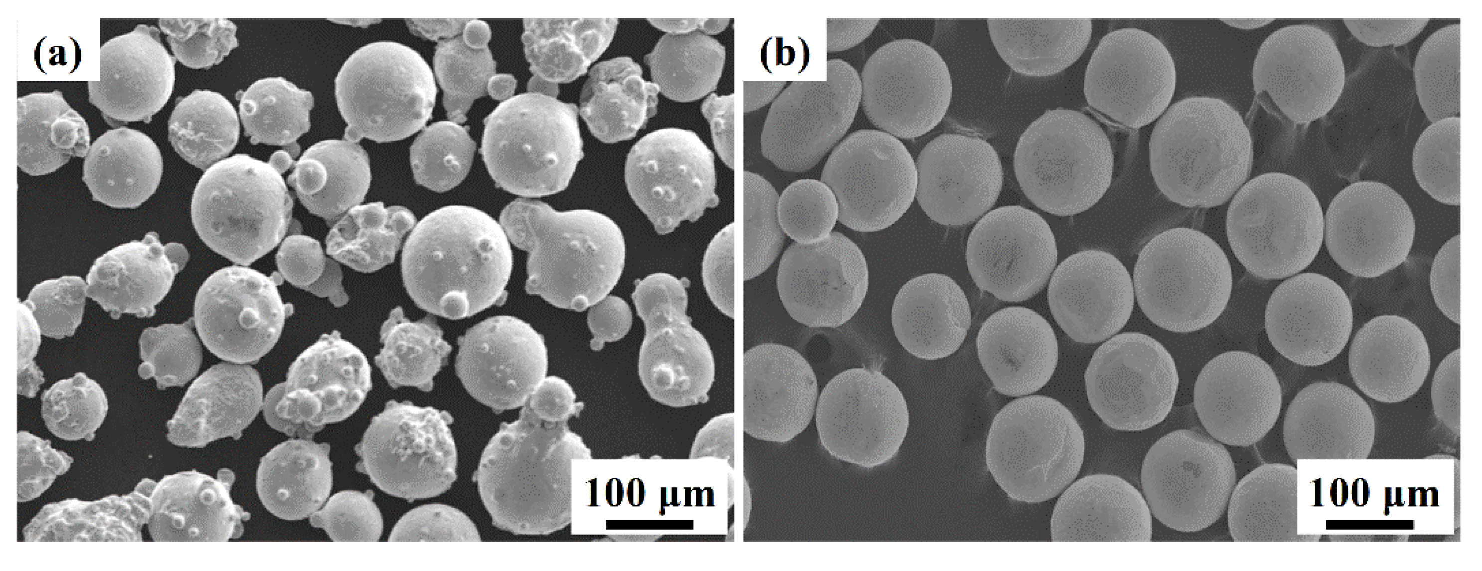
2.1. Experimental Materials

IN718 nickel-based alloy at the size of 50 mm × 40 mm × 5 mm was used as the substrate (Shenyang Institute of Rare Metals, Shenyang, China). The chemical compositions of the substrate are shown in Table 1. Raw powders (Shenyang Institute of Rare Metals, Shenyang, China) were a mixture of 70 wt.% of IN718 alloy powder and 30 wt.% of spherical WC particles. The average particle size of the composite powders ranged from 50 to 110 μm, as shown in Figure 1.

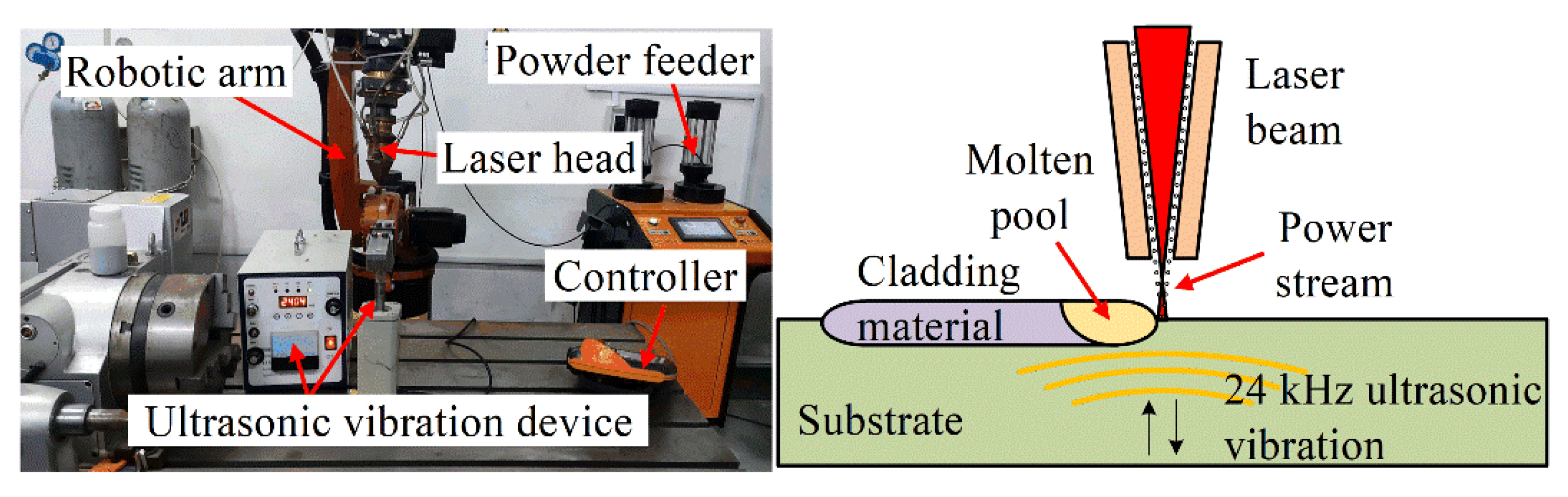
2.2. Experimental Methods

The coatings were fabricated by a 2-kW fiber laser system (YLS-2000-TR, IPG, Burnach, Germany). The vibration frequency of the ultrasonic vibration device (CYCS-300TJ, Chiyu Ultrasonic Equipment, Jinhua, China) was adjustable from 20 kHz to 80 kHz, and the maximum amplitude was 30 μm. The experimental device and schematic diagram of laser cladding process assisted by ultrasonic vibration are shown in Figure 2.
Orthogonal experiments were carried out on different process parameters based on the porosity, cracks, and surface forming quality. The optimized laser parameters were listed as follows: a laser power of 1300 W, a spot diameter of 2 mm, a scanning speed of 450 mm/min, a powder feeding rate of 10 g/min, and an overlap rate of 50%. In order to investigate the influence of ultrasonic vibration on the microstructure and properties of the composite coatings, the frequency of ultrasonic vibration was set at 24 kHz, and the amplitude was 25 μm, according to the previous publication [17,19].
The specimens were cut along the direction perpendicular to the scanning direction for grinding and polishing. All specimens were corroded with a solution of 30% HCl, 20% HF, and 50% HNO3. The macrostructure and microstructure of the coatings were observed by optical microscope (OM; VH-Z100R, Keyence, Osaka, Japan) and scanning electron microscope (SEM; S-3400N, Hitachi, Ibaraki, Japan), respectively. The phase compositions analysis of the cladding layers was performed by X-ray Diffraction (XRD; D8 ADVANCE, Bruker, Ettlingen, Germany). A semiautomatic microhardness tester (HXS-1000, Shante Instrument, Shanghai, China) was used to measure the microhardness of coatings. The load of 200 g was applied and maintained for 15 s. The hardness values were measured at intervals of 0.1 mm along the cross-section from coating surface to substrate. Each hardness was measured at three points at the same depth to obtain an average value. Additionally, the wear tests were conducted on the rotary wear testing machine (HT-1000, Kaihua Technology, Zhejiang, China). On the premise that the wear parameters of different coatings are consistent, the COF of each coating at the stable wear stage can reflect the differences of the wear properties. Therefore, according to the previous research, the wear tests were carried out with a load of 1000 g, a wear diameter of 4 mm, a loading time of 20 min, and a rotating speed of 500 r/min. The Si3N4 ball with a diameter of 6mm was used as the grinding ball. The profiles of the wear tracks were measured by laser scanning confocal microscope (LSCM; VK-X200, Keyence, Osaka, Japan), and the surface morphologies of the worn specimens were observed by SEM to analyze the wear mechanism of the coatings.

3. Results and Discussion

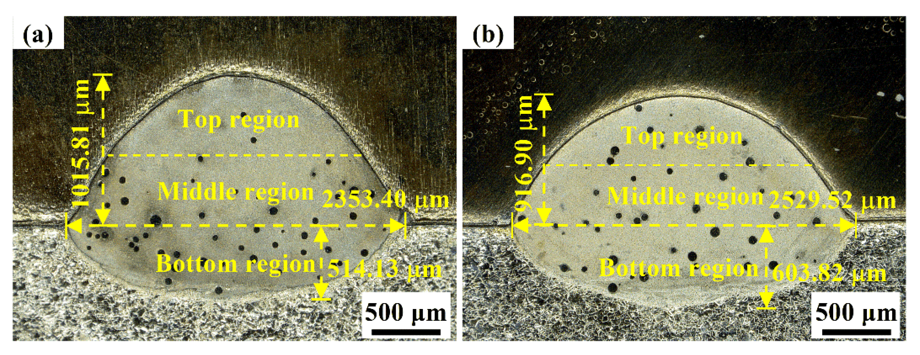
3.1. Macroappearance

Figure 3 reveals the morphology of typical cross-sectional the composite coatings with or without ultrasonic assistance. There are no pores or cracks at the bonding interface between the bottom of the molten pool and the substrate, indicating that the coating has a good metallurgical bonding with substrate. As can be seen from Figure 3a, the WC particles in the coating are mainly concentrated at the middle and bottom regions. This can be attributed to the density difference between WC and Ni matrix. The convection in the molten pool without ultrasonic vibration is weak and unable to prevent WC particles from sinking [20]. As shown in Figure 3b, the dilution rate of the coating increases slightly after the addition of ultrasonic vibration, and the WC particles gathered at the bottom of the coating show an upward trend. The cavitation, acoustic flow, and mechanical agitation generated by vibration enhance the flow of metal melt and significantly improve the spatial distribution of WC particles.

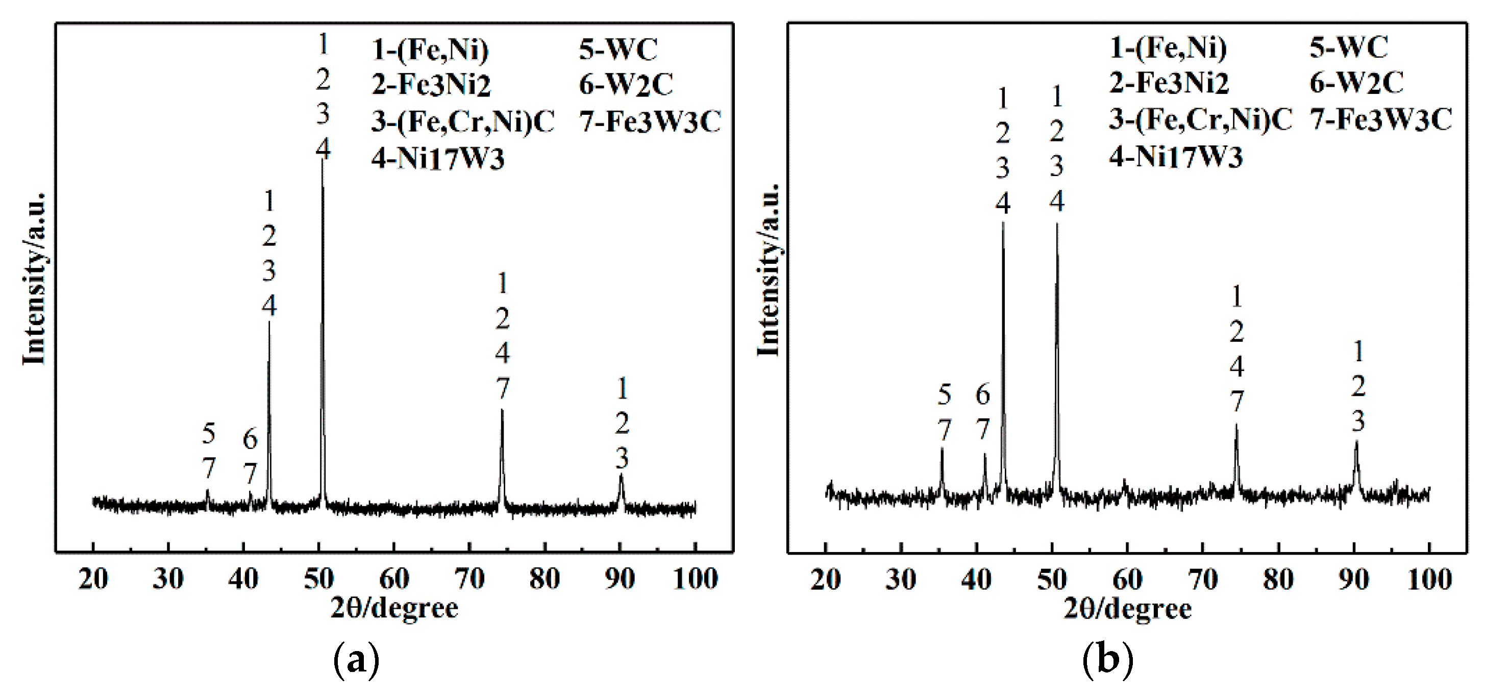
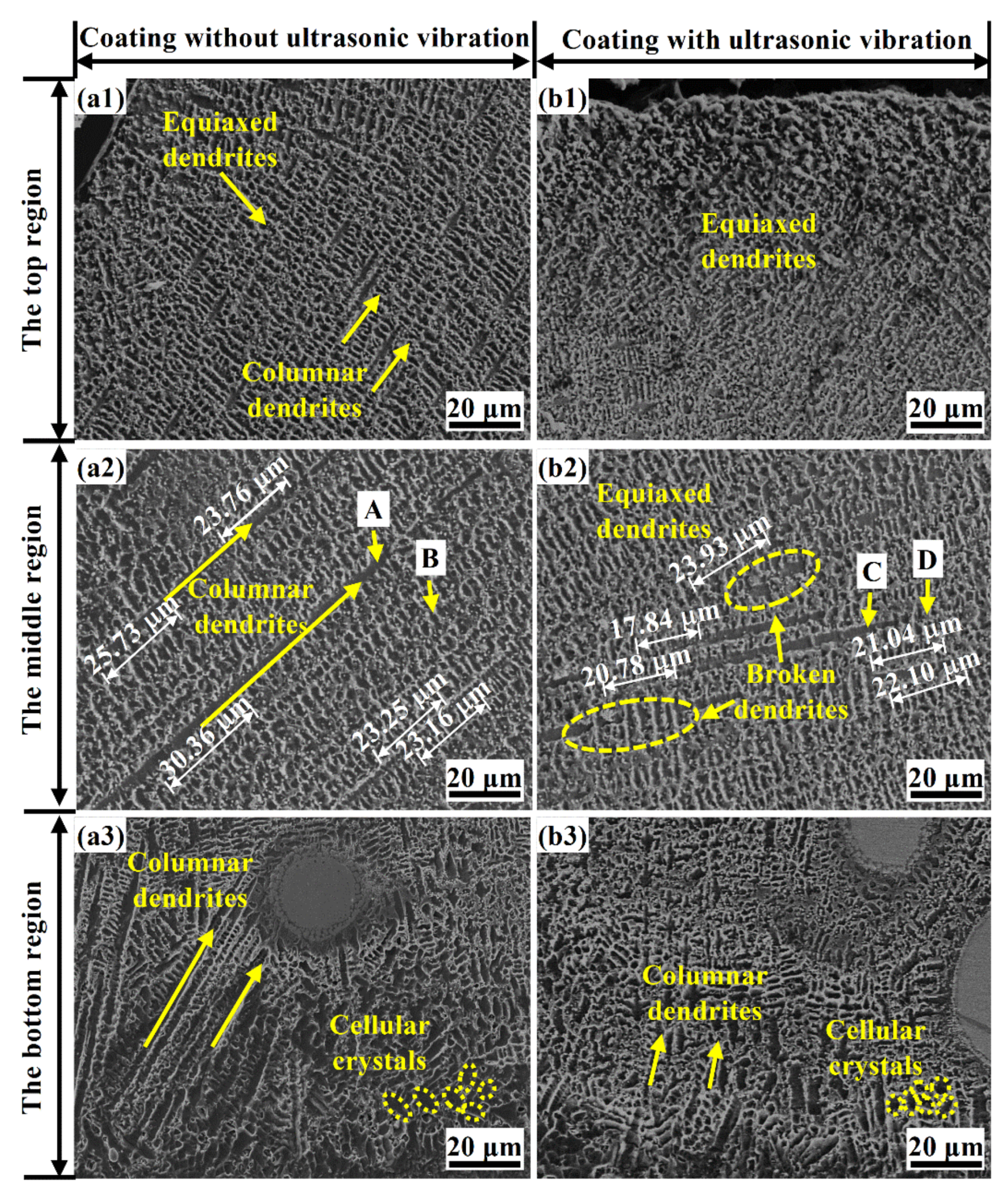
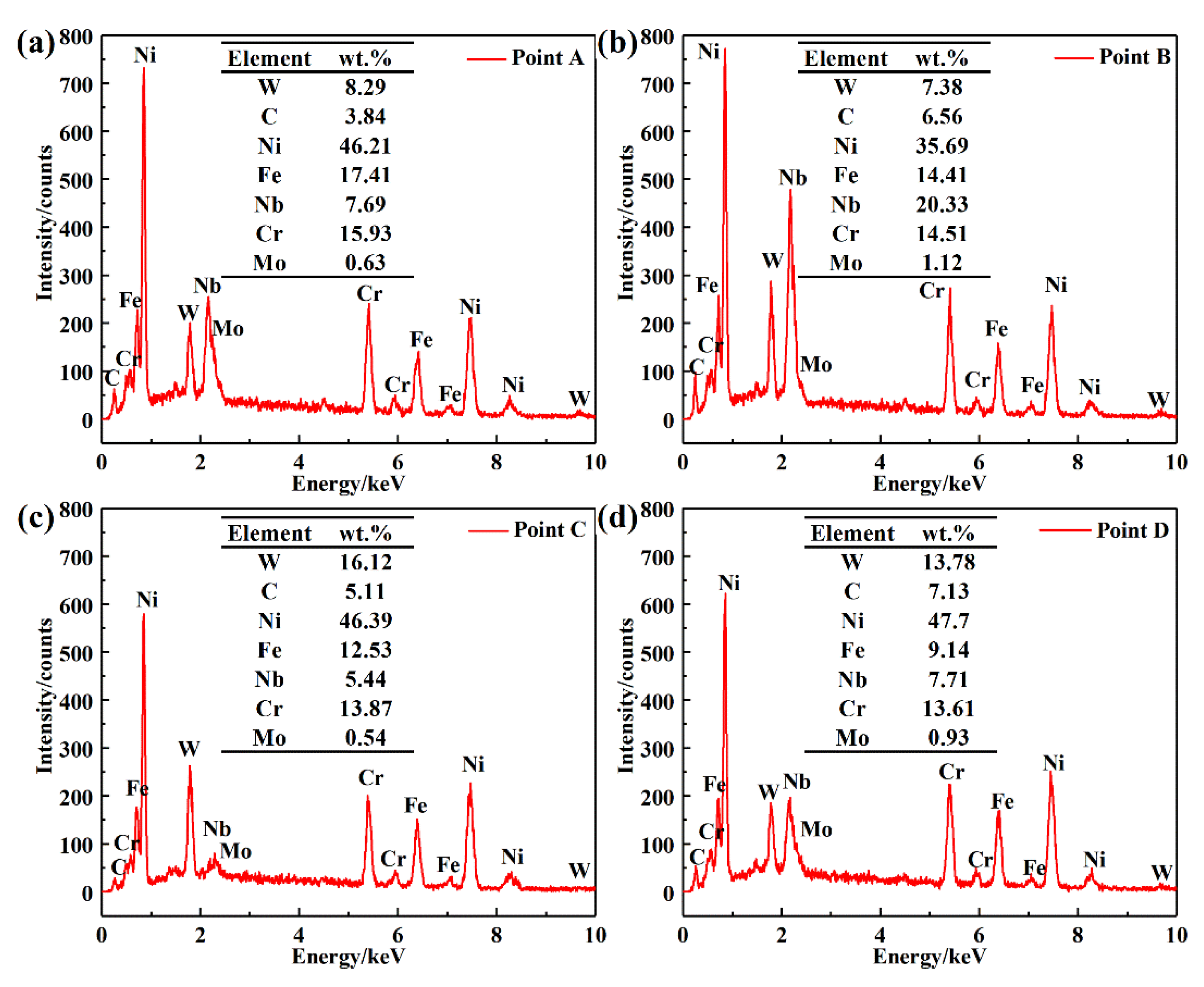
3.2. Composition and Microstructure

The XRD patterns of IN718/WC coatings are shown in Figure 4. It can be observed that the phase composition of the two coatings is consistent. During the laser cladding process, IN718 powder and WC particles have a metallurgical reaction and generate γ-(Fe, Ni) solid solution (JCPDS No. 47-1417), Fe3W3C (JCPDS No. 78-1990), (Fe, Cr, Ni)C (JCPDS No. 31-0619), Fe3Ni2 (JCPDS No. 65-5131), Ni17W3 (JCPDS No. 65-4828), WC (JCPDS No. 73-0471), W2C (JCPDS No. 79-0743), and other phases It can be observed that the intensity of the diffraction peaks of carbides such as W2C and Fe3W3C increases after ultrasonic vibration is applied. This can be attributed to the enhancement of convection by ultrasonic vibration, and the diffusion of W and C elements in the molten pool is stronger, forming harder phases.
Through further analysis of the XRD results based on the data in Table 2, it can be found that all the diffraction peaks shift to the right by a small angle after applying ultrasonic vibration. According to the Bragg Equation [21]:
2 d sin θ = n λ
where d is the spacing between corresponding crystal planes, θ is the included angle between the incident X-ray and crystal planes, and λ is X-ray wavelength. The increase of the angle means that the crystal plane spacing decreases.
In addition, the full width at half-maximum (FWHM) increases at the same diffraction angle. According to the Scherrer equation:
D = K λ B cos θ
where D is the value of grain size, K is Scherrer constant, and B is FWHM. In the case of the same material and diffraction angle, the FWHM is inversely proportional to the grain size. Therefore, the grain size of the ultrasonic vibration-assisted coating is reduced, indicating a significant grain refinement effect.
The microstructure characteristics of coatings with or without ultrasonic vibration from the top region to the bonding area are shown in Figure 5. According to Tiller supercooling theory [22], microstructure morphology formed in the solidification process is mainly affected by the ratio of the temperature gradient (G) in front of the solid–liquid interface to the solidification rate (R). The decrease value of G/R is conducive to the equiaxed dendrites formation. The correlation between R of molten pool and laser scanning speed v can be written as follows [23]:
R = v cos α
where α is the included angle between the scanning direction and normal line of the molten pool boundary. The α value tends to be 0° at the top region, which indicates that the G/R at the liquid–gas interface at the top region is the smallest, resulting in the coexistence of short dendrites and equiaxed dendrites, as presented in Figure 5(a1). The G/R value at the middle region of the coating increases, which leads to long columnar dendrite formation with well-developed primary dendrite arms, as shown in Figure 5(a2). Although the G at the molten pool bottom is slightly lower, the R at the bottom is close to 0, and G/R reaches the maximum. Consequently, Figure 5(a3) presents that a small number of cellular crystals and a large number of columnar dendrites are generated at the bonding interface.
As shown in Figure 5(b1–b3), in contrast to unassisted laser cladding, significant microstructure refinements occur in the coating after the application of ultrasonic vibration. It can be observed that large numbers of equiaxed crystals fill the whole top region and are more evenly distributed in Figure 5(b1). The microstructure of the coating has an obvious equiaxed tendency in the middle region, with the diminution of the length of the dendrites in Figure 5(b2). This can be attributed to the stirring action of ultrasonic vibration during crystal growth, which accelerates the flow of metal melt and reduces the temperature inhomogeneity and temperature gradient of the whole melt. Therefore, the G/R value at the same position is smaller than unassisted coating. Under the ultrasonic vibration treatment, columnar dendrites are broken into short dendrites, showing a mixed distribution of misaligned short dendrites and equiaxed dendrites. Although the microstructure characteristics of cellular dendrites and columnar dendrites at the bottom region are similar to those of the unassisted coating, the number and length of columnar dendrites are lower, as shown in Figure 5(b3). The analysis reveals that ultrasonic vibration promotes the coating microstructure transformation from coarse columnar dendrites to fine equiaxed dendrites.
For further understanding of the ultrasonic effects on the dendrite structure, five regions are selected in Figure 5(a2,b2). The linear intercept method is adopted to measure the linear length passing through ten secondary dendrites, and the average secondary dendrite arm spacing λ2 can be calculated. As shown in Table 3, it can be found that the average λ2 of the ultrasonic vibration-assisted coating is smaller than the unassisted coating, with a decrease of 16.28%. According to the heat and mass transfer theory, the relationship between the metal cooling rate V and secondary dendrite arm spacing λ2 is given as follows [24]:
λ 2 = β V n
where β is a constant related to the alloy, and n ranges from 0.2 to 0.4. Since the coatings were made by the same powders, the decrease of λ2 proves the increase of the cooling rate, indicating the influence of ultrasonic vibration on the melt temperature gradient.
The microstructure of the coatings with or without ultrasonic vibration is mainly composed of dark gray dendrites (points A and C) and light gray inter-crystalline phases (points B and D). Figure 6 presents the EDS analysis of the points marked in Figure 5(a2,b2).
Combined with the XRD results, phases A and C are γ-(Fe, Ni) solid solutions, and phases B and D can be identified as eutectic structures (containing γ-(Fe, Ni), carbides Fe3W3C, (Fe, Cr, Ni)C). As shown in Figure 6, the content of the W element in phases C and D is obviously higher than that in phases A and B, which implies that the decomposition of WC in the ultrasonic vibration-assisted coating is more intense and more reinforcing for when phases containing the W element are formed. Additionally, by comparing phase A and phase B, it can be found that severe segregation of the Nb and Mo elements occurs during the formation of precipitated phases. Under the action of ultrasound, the content of the Nb element is significantly reduced from 20.33 to 7.71 wt.%, and the mass fraction of the Nb element is reduced by 62% compared with the unassisted coating. The above results indicate that ultrasonic vibration promotes the generation of hard phases in the coating [25] and significantly inhibits element segregation, which is conducive to improving the comprehensive mechanical properties of the coating.

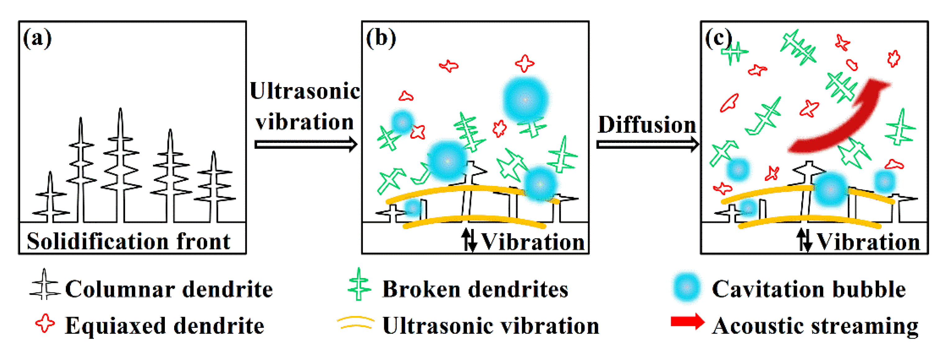
3.3. Influence Mechanism of Ultrasonic Vibration

Cavitation bubbles occur in the molten pool under the action of ultrasonic vibration [26]. In the process of expansion, the cavitation bubbles absorb a large amount of heat from the surrounding metal melt. As the melt temperature decreases, the supercooling degree of the local region increases. The nucleation energy barrier of liquid metal ΔG can be calculated as follows:
Δ G = 4 π γ 2 3 T m Δ T Δ H m 2 2 3 cos θ + cos 3 θ
where γ is the free energy of the solid–liquid phases, Tm is the theoretical crystallization temperature, ΔT is the supercooling degree, ΔHm is latent heat of melting, and θ is the wetting angle. As the supercooling degree increases, the nucleation energy barrier decreases, which is conducive to nucleation. At the same time, the intense shockwave generated by the closure and rupture of the bubble leads to the formation of a high-pressure microregion (about 1000–2500 atm). The abrupt change of pressure greatly increases the rate of nucleation at the beginning of solidification and ultimately enhances grain refinement.
Figure 7 shows the solidification crystallization process of laser cladding. As shown in Figure 7a, the temperature gradient G of the unassisted coating maintains a high level, and the G/R value is larger. Therefore, nucleation occurs at the edge of the solid–liquid interface, and a large number of coarse columnar dendrites with obvious growth orientation are formed. As shown in Figure 7b, after the introduction of ultrasonic vibration, the high pressure generated at the moment of collapse of the cavitation bubble forms a microjet (about 80 m·s−1–130 m·s−1) [27], which produces the impact force on the solid–liquid interface. With the continuous growth of dendrites, the circular scour effect caused by strong convection finally breaks the dendrite tip. On the other hand, the continuous enrichment of solute occurs at the shrinkage neck of the dendrite root [28]. The intense stirring of ultrasonic vibration during crystal growth intensifies the thermal convection around the dendrites and forms a strong thermal disturbance, which makes the root of the dendrite prone to fuse. Therefore, misaligned broken dendrites are formed in the coating (marked with green in Figure 7), which can also be found in Figure 5(b2). The mechanical scour and heat flow promote grain proliferation. With the flow of the molten pool, the broken dendrites float in the molten pool, which makes the final solidified grains evenly distributed, as shown in Figure 7c. In conclusion, ultrasonic vibration weakens the growth conditions of columnar dendrites and promotes the transformation of the coating microstructure from dendrites with a specific orientation to fine equiaxed crystals.

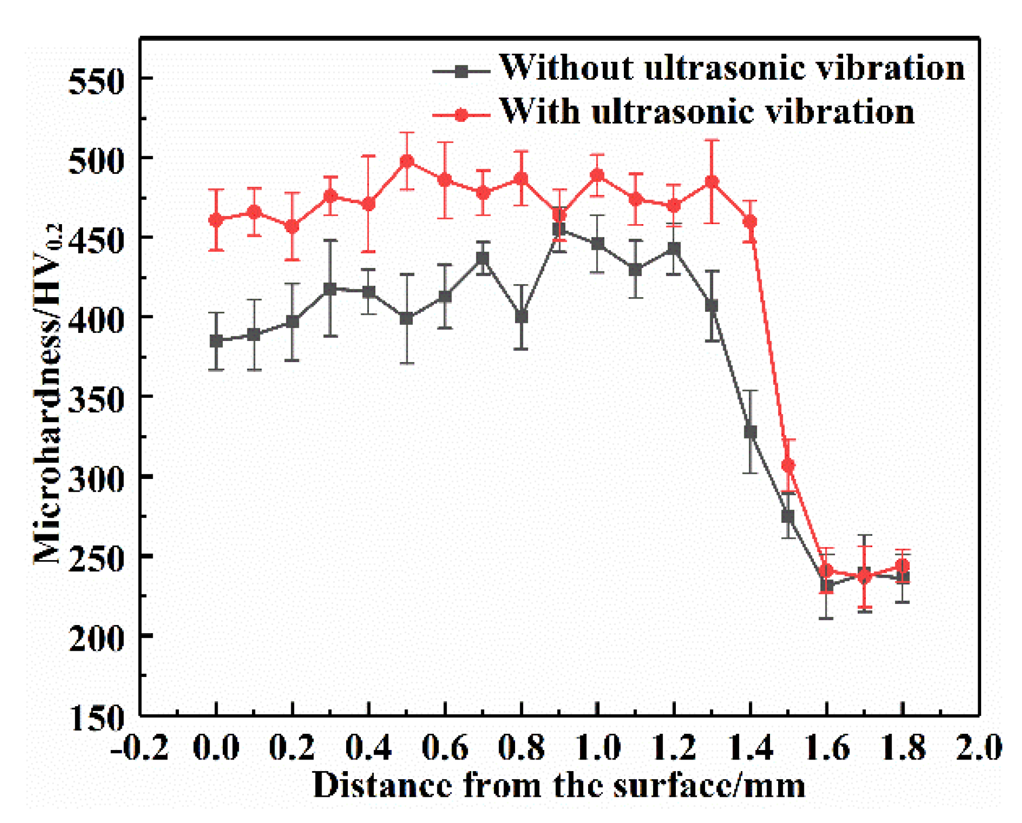
3.4. Microhardness Distribution
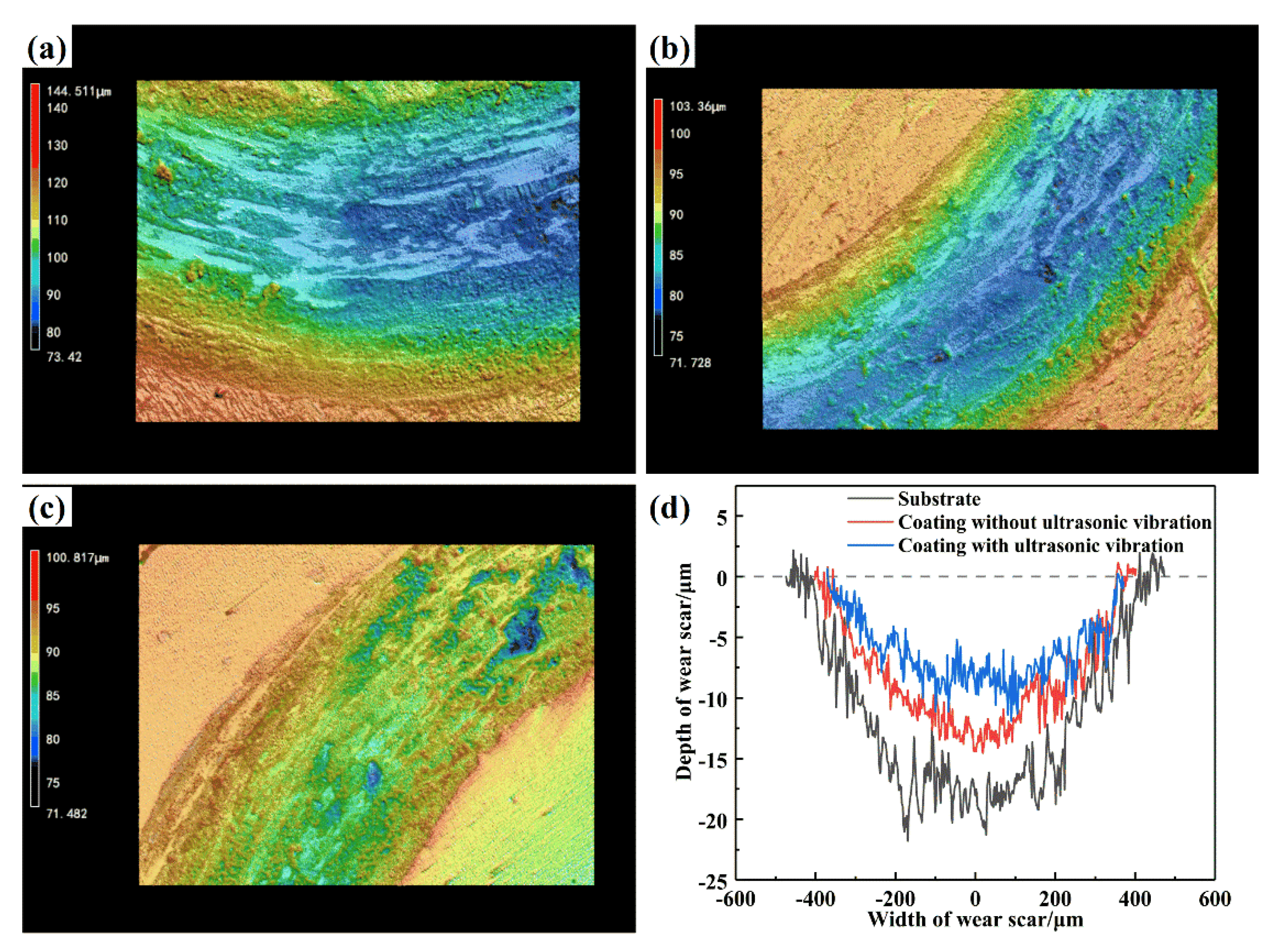
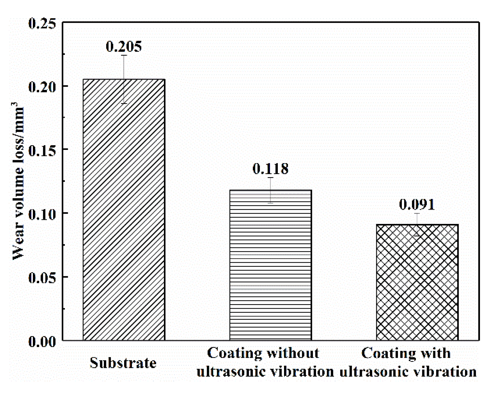
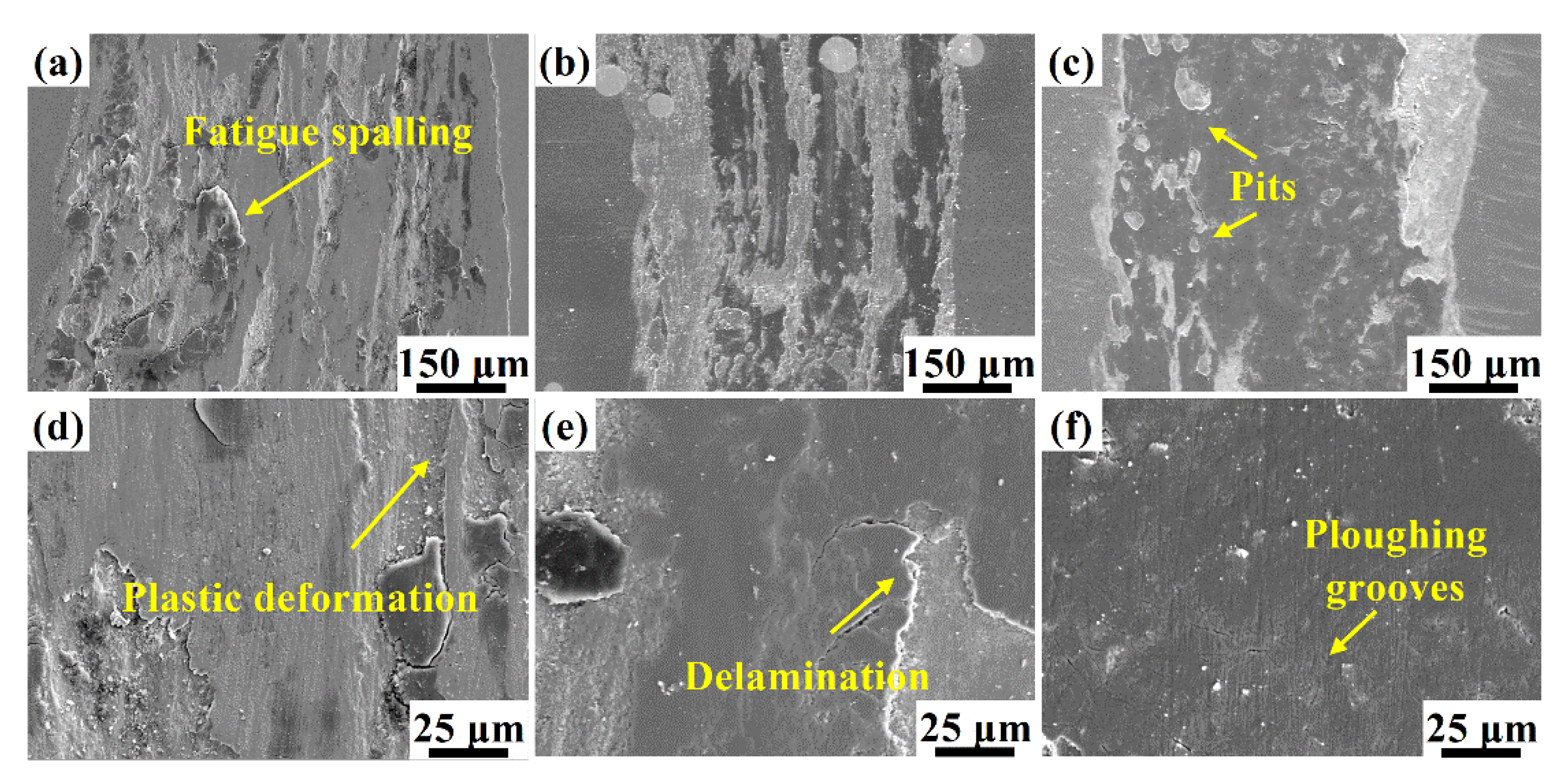
Figure 8 shows the microhardness distributions along the depths of coatings with or without ultrasonic vibration. The hardness curves can be divided into three stages, corresponding to the coating, heat-affected zone, and substrate. The microhardness of substrate is about 230 HV0.2, while that of the unassisted IN718/WC composite coating reaches 411 HV0.2. However, as shown in Figure 3a, the microhardness of its bottom region increases slightly due to the deposition of the WC particles, showing regional fluctuation. With the action of ultrasonic vibration, the average microhardness reaches 475 HV0.2, which is more than twice the substrate, and 15.6% higher than the unassisted coating. By analyzing results of SEM and EDS, it can be concluded that ultrasonic vibration can significantly improve the microhardness of the cladding layer. The microstructure of the clad coating is refined, and the dislocation movement and grain boundary migration are hindered by the fine grain-strengthening effect produced by ultrasonic vibration. In addition, cavitation and acoustic flow generated by ultrasonic vibration contribute to the decomposition of WC particles and produce more reinforcing phases to improve the microhardness [29]. Moreover, the segregation of Nb, Mo, and other elements is inhibited, which makes more strengthening elements dissolved in the γ phase. In addition, the fluctuation of the microhardness of the coating is decreased obviously under ultrasonic vibration. Owing to the stirring action generated by ultrasonic vibration, the melt flow is promoted, and the hard phase is uniformly distributed, which makes the coating hardness distribution more uniform along the depth direction.

3.5. Wear Behavior

The dynamic COF curves of three specimens are shown in Figure 9. The substrate obtains the highest average COF of 0.648, and the unassisted IN718/WC composite coating is 15.4% lower, which is 0.548. It indicates that WC particles increase the type and quantity of reinforcing phases in the coating, which is beneficial to improve the wear resistance of the coating. Comparatively, under the application of ultrasonic vibration, the COF reaches the lowest value of 0.452. Relevant studies [30,31] have shown that grain refinement and reinforcing phases can improve the hardness and wear resistance. Introducing ultrasonic vibration into the composite coating can refine grains and promote the decomposition of WC particles. Therefore, the addition of ultrasonic vibration makes a great contribution to the further improvement of the wear resistance.
Figure 10a–c shows the 3D contours of the wear marks of the substrate and coatings. The 2D section of the wear traces are shown in Figure 10d. Both the width and depth of the matrix wear marks are the largest, and the values show intense fluctuation. When WC particles are added during the reinforcing phase, the wear marks of the coating become narrower and shallower. The wear trace morphology of the coating produced by ultrasonic vibration shows the minimum.
The wear volume loss of specimens ΔV can be calculated as follows:
Δ V = 2 π r · S
where r is the friction radius of the track; S is the average area of the cross-section of the wear mark. Figure 11 shows the wear volume loss of the three specimens. The wear volume loss of the matrix material is 0.205 mm3 and that of the unassisted IN718/WC composite coating is reduced by 42.4% to 0.118 mm3. The significantly reduced volume loss indicates that the addition of WC ceramic particles as an enhancement can improve the surface wear resistance. The volume loss of the ultrasonic vibration-assisted coating is 0.091 mm3, which is 55.6% and 22.9% lower than that of the substrate and unassisted coating, respectively. The results show that ultrasonic vibration can further reduce the wear volume loss.
The wear volume of the coating is inversely related to the microhardness when the experimental load and slip distance remain unchanged. With the increase of the surface hardness, the depth of the grinding ball into the material is shallower, and the volume loss caused by friction is less. Under the action of ultrasonic vibration, the formation of large amounts of reinforcing phases improves the coating hardness and the ability of the material to resist the surface extrusion of the grinding ball. Additionally, the undecomposed WC particles are evenly distributed in the coating as high hardness phases to prevent the wear of the grinding ball on the softer coating material. Therefore, the wear volume loss of the coating is reduced, and the wear resistance of the coating is improved.
To further analyze the wear mechanism, Figure 12 reveals the wear morphologies of the substrate and coatings. Figure 12a,d shows that there are large numbers of fatigue spalling areas and severe plastic deformation in the substrate wear mark, indicating that severe adhesive wear occurred. The friction between the specimen and grinding ball does not contact the whole surface, but the grinding ball invades the soft matrix through point contact and plows the surface under the action of tangential force. Due to the small contact area and excessive local stress, the contact point is torn from the relative motion, resulting in material spalling and severe plastic deformation.
Figure 12b,e indicates that the adhesive wear degree of composite coating is better than that of the substrate, as some large deformation areas disappeared. Although large scales of spalling still exist and partial connection bonding areas are formed, the area and depth of the spalling zones are much less than the substrate, indicating that the addition of WC particles improves the coating wear resistance. WC particles have the function of dispersion enhancement [32,33], which can disperse the load on the contact point of WC to reduce the friction on the soft matrix. Therefore, the dispersed WC particles can effectively reduce the ploughing generated during sliding wear so as to protect the softer nickel-based materials and reduce wear. Meanwhile, the reinforcing phases produced by the decomposition of WC improve the hardness and bonding strength of the coating, effectively reducing the adhesion and shear phenomenon in the wear test. However, due to the uneven distribution of WC in the unassisted coating, the content of the WC particles in the top and middle areas (friction area) of the coating is small, leading to the existence of partial spalling.
As shown in Figure 12c,f, several parts of the original coating are retained after the sliding wear with several shallow ploughing grooves and slight adhesive pits. It can be demonstrated that, under ultrasonic vibration, the WC particles distribution is more uniform, and the increase of WC particles in the top and middle regions makes the dispersion strengthening effect more significant. Under the effect of the reinforcing phases, the ability of the coating to resist the invasion of the grinding ball is further enhanced. Therefore, there are fewer spalling pits on the wear scar of the coating with ultrasonic vibration. Additionally, the grain refinement enhances the toughness of the coating, thus preventing the generation and propagation of cracks. It can be inferred that ultrasonic vibration can effectively reduce adhesive wear, and the wear mechanism of the coating transforms into a coexistence of slight abrasive wear and adhesive wear.

4. Conclusions

WC-reinforced nickel-based coatings were prepared by ultrasonic vibration-assisted laser cladding. The influences of ultrasonic vibration on the WC particle distribution, microstructure, and wear performance were investigated. The main conclusions are as follows:
(1)
Ultrasonic vibration treatment does not change the phase composition but enhances the pool convection and optimizes the uniform distribution of WC particles. It promotes the decomposition of WC particles and element diffusion and thus improves the dispersion-strengthening effect of the reinforcing phase.
(2)
Ultrasonic vibration produces agitation to the liquid melt, which fractures the columnar dendrites and promotes transformation of the coating microstructure from coarse dendrites to fine dendrites and equiaxed dendrites.
(3)
Under the combined effects of fine grain enhancement, dispersion enhancement, and elemental segregation inhibition caused by ultrasonic vibration, the microhardness is increased by 15.6% to 475 HV0.2 and presents more uniform distribution.
(4)
The friction coefficient of the composite coating decreases from 0.548 to 0.452 with the assistance of ultrasonic vibration, and the wear mechanism changes to slightly abrasive wear and adhesive wear.

Author Contributions

Conceptualization, J.Z.; methodology, J.Z.; validation, J.L. and T.Z.; formal analysis, T.Z. and P.L.; investigation, J.L.; resources, J.Z., X.M. and S.H.; data curation, J.L.; writing—original draft preparation, J.L.; writing—review and editing, J.Z.; visualization, J.L. and P.L.; supervision, J.Z.; project administration, J.Z.; and funding acquisition, J.Z., X.M. and S.H. All authors have read and agreed to the published version of the manuscript.

Funding

This research was funded by the National Natural Science Foundation of China (grant number 51875265).

Institutional Review Board Statement

Not applicable.

Informed Consent Statement

Not applicable.

Data Availability Statement

Not applicable.

Conflicts of Interest

The authors declare no conflict of interest.

References

  1. Fernández, M.R.; García, A.; Cuetos, J.M.; González, R.; Noriega, A.; Cadenas, M. Effect of actual WC content on the reciprocating wear of a laser cladding NiCrBSi alloy reinforced with WC. Wear 2015, 324–325, 80–89. [Google Scholar] [CrossRef]
  2. Chen, S.L.; Zhou, J.Z.; Huang, S.; Zhang, H.C. Mechanism of hot corrosion resistance of IN718 superalloy strengthened by laser peening. J. Drain. Irrig. Mach. Eng. 2021, 39, 1068–1074. [Google Scholar] [CrossRef]
  3. Mohseni, H.; Nandwana, P.; Tsoi, A.; Banerjee, R.; Scharf, T.W. In situ nitrided titanium alloys: Microstructural evolution during solidification and wear. Acta Mater. 2015, 83, 61–74. [Google Scholar] [CrossRef]
  4. Guo, L.L.; Qin, L.; Kong, F.Y.; Yi, H.; Tang, B. Improving tribological properties of Ti-5Zr-3Sn-5Mo-15Nb alloy by double glow plasma surface alloying. Appl. Surf. Sci. 2016, 388, 203–211. [Google Scholar] [CrossRef]
  5. Zhang, Z.; Yu, T.; Kovacevic, R. Erosion and corrosion resistance of laser cladded AISI 420 stainless steel reinforced with VC. Appl. Surf. Sci. 2017, 410, 225–240. [Google Scholar] [CrossRef]
  6. Yang, C.Y.; Cheng, X.; Tang, H.B.; Tian, X.J.; Liu, D. Influence of microstructures and wear behaviors of the microalloyed coatings on TC11 alloy surface using laser cladding technique. Surf. Coat. Technol. 2018, 337, 97–103. [Google Scholar] [CrossRef]
  7. Paul, C.P.; Mishra, S.K.; Tiwari, P.; Kukreja, L.M. Solid-Particle Erosion Behaviour of WC/Ni Composite Clad layers with Different Contents of WC Particles. Opt. Laser Technol. 2013, 50, 155–162. [Google Scholar] [CrossRef]
  8. Wang, H.R.; Sun, Y.F.; Qiao, Y.Z.; Du, X.S. Effect of Ni-coated WC reinforced particles on microstructure and mechanical properties of laser cladding Fe-Co duplex coating. Opt. Laser Technol. 2021, 142, 107209. [Google Scholar] [CrossRef]
  9. Huo, K.; Zhou, J.Z.; Dai, F.Z.; Xu, J.L. Particle distribution and microstructure of IN718/WC composite coating fabricated by electromagnetic compound field-assisted laser cladding. Appl. Surf. Sci. 2021, 545, 149078. [Google Scholar] [CrossRef]
  10. Huebner, J.; Kata, D.; Rutkowski, P.; Petrzak, P.; Kusiński, J. Grain-Boundary Interaction between Inconel 625 and WC during Laser Metal Deposition. Materials 2018, 11, 1797. [Google Scholar] [CrossRef] [Green Version]
  11. Wang, K.M.; Du, D.; Liu, G.; Chang, B.H.; Hong, Y.X. Microstructure and properties of WC reinforced Ni-based composite coatings with Y2O3 addition on titanium alloy by laser cladding. Sci. Technol. Weld. Join. 2019, 24, 517–524. [Google Scholar] [CrossRef]
  12. Xie, S.Y.; Li, R.D.; Yuan, T.C.; Chen, C.; Zhou, K.C.; Song, B.; Shi, Y.S. Laser cladding assisted by friction stir processing for preparation of deformed crack-free Ni-Cr-Fe coating with nanostructure. Opt. Laser Technol. 2018, 99, 374–381. [Google Scholar] [CrossRef]
  13. Weng, Z.K.; Wang, A.H.; Wu, X.H.; Wang, Y.Y.; Yang, Z.X. Wear resistance of diode laser-clad Ni/WC composite coatings at different temperatures. Surf. Coat. Technol. 2016, 304, 283–292. [Google Scholar] [CrossRef]
  14. Liu, Y.; Huang, Y.C.; Xiao, Z.B. Effect of ultrasonic casting on microstructure and its genetic effects on corrosion performance of 7085 aluminum alloy. Phys. Met. Metallogr. 2017, 118, 1105–1112. [Google Scholar] [CrossRef]
  15. Liu, J.; Zhu, H.Y.; Li, Z.; Cui, W.F.; Shi, Y. Effect of ultrasonic power on porosity, microstructure, mechanical properties of the aluminum alloy joint by ultrasonic assisted laser-MIG hybrid welding. Opt. Laser Technol. 2019, 119, 105619. [Google Scholar] [CrossRef]
  16. Todaro, C.J.; Easton, M.A.; Qiu, D.; Zhang, D.; Bermingham, M.J.; Lui, E.W.; Brandt, M.; StJohn, D.H.; Qian, M. Grain structure control during metal 3D printing by high-intensity ultrasound. Nat. Commun. 2020, 11, 365–369. [Google Scholar] [CrossRef] [PubMed]
  17. Xu, J.L.; Zhou, J.Z.; Tan, W.S.; Huang, S.; Wang, S.T.; He, W.Y. Ultrasonic vibration on wear property of laser cladding Fe-based coating. Surf. Eng. 2018, 36, 1261–1269. [Google Scholar] [CrossRef]
  18. Biswas, S.; Alavi, S.H.; Sedai, B.; Blum, F.D.; Harimkar, S.P. Effect of ultrasonic vibration-assisted laser surface melting and texturing of Ti-6Al-4V ELI alloy on surface properties. J. Mater. Sci. Technol. 2019, 35, 295–302. [Google Scholar] [CrossRef]
  19. Zhang, T.; Li, P.F.; Zhou, J.Z.; Wang, C.Y.; Meng, X.K.; Huang, S. Microstructure evolution of laser cladding Inconel 718 assisted hybrid ultrasonic-electromagnetic field. Mater. Lett. 2021, 289, 129401. [Google Scholar] [CrossRef]
  20. Ortiz, A.; García, A.; Cadenas, M.; Fernández, M.R.; Cuetos, J.M. WC particles distribution model in the cross-section of laser cladded NiCrBSi + WC coatings, for different wt% WC. Surf. Coat. Technol. 2017, 324, 298–306. [Google Scholar] [CrossRef]
  21. Liu, Y.F.; Zhuang, S.G.; Liu, X.B.; OuYang, C.S.; Zhu, Y.; Meng, Y. Microstructure evolution and high-temperature tribological behavior of Ti3SiC2 reinforced Ni60 composite coatings on 304 stainless steel by laser cladding. Surf. Coat. Technol. 2021, 420, 127335. [Google Scholar] [CrossRef]
  22. Tiller, W.A.; Jackson, K.A.; Rutter, J.W.; Chalmers, B. The redistribution of solute atoms during the solidification of metals. Acta Metall. 1953, 1, 428–437. [Google Scholar] [CrossRef]
  23. Gan, Z.T.; Yu, G.; He, X.L.; Li, S.X. Numerical simulation of thermal behavior and multicomponent mass transfer in direct laser deposition of Co-base alloy on steel. Int. J. Heat Mass Transf. 2017, 104, 28–38. [Google Scholar] [CrossRef] [Green Version]
  24. Mullis, A.M.; Farrell, L.; Cochrane, R.F.; Adkins, N.J. Estimation of Cooling Rates During Close-Coupled Gas Atomization Using Secondary Dendrite Arm Spacing Measurement. Metall. Mater. Trans. B 2013, 44, 992–999. [Google Scholar] [CrossRef] [Green Version]
  25. Li, C.G.; Zhang, Q.S.; Wang, F.F.; Deng, P.R.; Lu, Q.H.; Zhang, Y.F.; Li, S.; Ma, P.; Li, W.G.; Wang, Y. Microstructure and wear behaviors of WC-Ni coatings fabricated by laser cladding under high frequency micro-vibration. Appl. Surf. Sci. 2019, 485, 513–519. [Google Scholar] [CrossRef]
  26. Leighton, T.G. Bubble population phenomena in acoustic cavitation. Ultrason. Sonochem. 1995, 2, S123–S136. [Google Scholar] [CrossRef]
  27. Crum, L.A. Comments on the evolving field of sonochemistry by a cavitation physicist. Ultrason. Sonochem. 1995, 2, S147–S152. [Google Scholar] [CrossRef]
  28. Mathiesen, R.H.; Arnberg, L. Stray crystal formation in Al-20 wt.% Cu studied by synchrotron X-ray video microscopy. Mater. Sci. Eng. A 2005, 413–414, 283–287. [Google Scholar] [CrossRef]
  29. Li, M.Y.; Han, B.; Wang, Y.; Song, L.X.; Guo, L.Y. Investigation on laser cladding high-hardness nano-ceramic coating assisted by ultrasonic vibration processing. Optik 2016, 127, 4596–4600. [Google Scholar] [CrossRef]
  30. Aboulkhair, N.T.; Simonelli, M.; Salama, E.; Rance, G.A.; Neate, N.C.; Tuck, C.J.; Esawi, A.M.K.; Hague, R.J.M. Evolution of carbon nanotubes and their metallurgical reactions in Al-based composites in response to laser irradiation during selective laser melting. Mater. Sci. Eng. A 2019, 765, 138307. [Google Scholar] [CrossRef]
  31. Li, M.Y.; Han, B.; Song, L.X.; He, Q.K. Enhanced surface layers by laser cladding and ion sulfurization processing towards improved wear-resistance and self-lubrication performances. Appl. Surf. Sci. 2020, 503, 144226. [Google Scholar] [CrossRef]
  32. Leech, P.W.; Li, X.S.; Alam, N. Comparison of abrasive wear of a complex high alloy hardfacing deposit and WC–Ni based metal matrix composite. Wear 2012, 294–295, 380–386. [Google Scholar] [CrossRef]
  33. Guo, C.; Chen, J.M.; Zhou, J.S.; Zhao, J.R.; Wang, L.Q.; Yu, Y.J.; Zhou, H.D. Effects of WC–Ni content on microstructure and wear resistance of laser cladding Ni-based alloys coating. Surf. Coat. Technol. 2012, 206, 2064–2071. [Google Scholar] [CrossRef]
Figure 1. Morphologies of powder particles (a) IN718 and (b) WC.
Coatings 12 00412 g001
Figure 2. Experimental device and schematic diagram of laser cladding assisted by ultrasonic vibration.
Coatings 12 00412 g002
Figure 3. The typical cross-sectional morphologies of coatings (a) without ultrasonic vibration and (b) with ultrasonic vibration.
Coatings 12 00412 g003
Figure 4. XRD patterns of coatings (a) without ultrasonic vibration and (b) with ultrasonic vibration.
Coatings 12 00412 g004
Figure 5. Cross-sectional SEM microstructure of the coatings (a1a3) without ultrasonic vibration and (b1b3) with ultrasonic vibration; 1, 2, and 3 represent the top region, middle region and bottom region.
Coatings 12 00412 g005
Figure 6. EDS analysis of the marked points: (a) A, (b) B, (c) C, and (d) D.
Coatings 12 00412 g006
Figure 7. Mechanism of ultrasonic vibration in the solidification crystallization process. (a) crystallization process of unassisted coating; (b) cavitation bubble collapse and dendrite fracture process under ultrasound; (c) heterogeneous nucleation transited by acoustic streaming.
Coatings 12 00412 g007
Figure 8. Microhardness distributions of the coatings.
Coatings 12 00412 g008
Figure 9. Wear curves of the substrate and coatings.
Coatings 12 00412 g009
Figure 10. 3D contours of the wear marks: (a) substrate, (b) coating without ultrasonic vibration, (c) coating with ultrasonic vibration, and (d) contrast diagram of the wear traces.
Coatings 12 00412 g010
Figure 11. Wear volume loss of the substrate and coatings.
Coatings 12 00412 g011
Figure 12. SEM morphologies of wear marks: (a,d) substrate, (b,e) coatings without vibration, and (c,f) coatings with vibration.
Coatings 12 00412 g012
Table 1. IN718 substrate chemical composition (wt.%).
NiCrNbMoTiMnSiAlFe
53.0018.505.003.000.663.000.350.35Bal
Table 2. The calculations based on the XRD results.
Without Ultrasonic VibrationWith Ultrasonic Vibration
Bragg Diffraction Angle 2θ (°)FWHM (°)Bragg Diffraction Angle 2θ (°)FWHM (°)
35.2240.26135.3830.319
40.9180.22741.0640.297
43.3620.23643.4960.248
50.4810.21950.6190.276
74.2910.26774.4700.361
90.1690.36990.3230.445
Table 3. Secondary dendrite arm spacing.
SpecimensSecondary Dendrite Arm Spacing λ2 (μm)
D1D2D3D4D5Average
Without ultrasonic vibration2.3762.5733.0362.3252.3162.525
With ultrasonic vibration2.3931.7842.0782.1042.2102.114
Publisher’s Note: MDPI stays neutral with regard to jurisdictional claims in published maps and institutional affiliations.

