Article

Electrochemical Behavior of Cu-MWCNT Nanocomposites Manufactured by Powder Technology

1
Mechanical Department, Faculty of Technology and Education, Beni-Suef University, Beni Suef 62511, Egypt
2
Chemical and Electroprocessing Division Mineral Technology Dept., Central Metallurgical Research and Development Institute CMRDI, Cairo 11865, Egypt
3
Powder Technology Department, Central Metallurgical Research and Development Institute CMRDI, Cairo 11865, Egypt
4
Mechanical Engineering Department, Imam Mohammad Ibn Saud Islamic University, Riyadh 11432, Saudi Arabia
5
Department of Production Engineering and Mechanical Design, Tanta University, Tanta 31527, Egypt
6
Mechanical Engineering Department, Faculty of Engineering, Kafrelsheikh University, Kafrelsheikh 33516, Egypt
*
Author to whom correspondence should be addressed.
Coatings 2022, 12(3), 409; https://doi.org/10.3390/coatings12030409
Submission received: 15 January 2022 / Revised: 8 March 2022 / Accepted: 10 March 2022 / Published: 19 March 2022

Abstract

:
This paper presents an experimental investigation of the fabrication of Cu–multi-walled carbon nanotube (MWCNT) nanocomposites prepared via the electroless chemical deposition technique followed by the powder metallurgy (PM) method. To enhance the dispersion and wettability of MWCNTs with a Cu matrix, MWCNTs were given an electroless coating of Ag nanoparticles. MWCNTs with 0.4, 0.8, and 1.2 wt.% were first coated with 5 wt.% Ag nanoparticles, then mechanically milled with Cu nanoparticles using a 10:1 ball-to-powder ratio for 60 min at 300 rpm. The mixed samples (35 g) were subjected to a compression pressure of 700 MPa and sintered at 950 °C in a hydrogen-inert gas furnace. Mapping and microstructure analyses were conducted to analyze the constituents’ homogeneity. In addition, the electrochemical properties and corrosion resistance of specimens were investigated. The results revealed that the relative density decreased by raising the MWCNTs’ content. Electrical resistivity increased gradually with the addition of MWCNTs coated by Ag nanoparticles, and the thermal conductivity decreased. It was also revealed that the smallest corrosion rate could be obtained for the sample with 1.2 wt.% MWCNTs, which is the appropriate rate for the electrochemical deposition.

1. Introduction

Composite materials have received increased interest in different engineering fields [1,2,3]. They are composed of distinct, blended constituents with different physical, chemical, thermal, and mechanical properties [4]. Metal matrix composites (MMCs) are one of the most frequently used composite materials in which a metallic matrix is reinforced with fibers or ceramic particles [5]. MMCs have outstanding mechanical properties such as a high specific strength and elasticity modulus compared to base alloys [6]. The combination of the constituents’ properties, such as the toughness and ductility of the matrix and the high tensile strength and elasticity modulus of the reinforcements, is crucial to obtaining high-strength composites [7]. MMCs have been used in many engineering applications, such as automotive, aerospace, defense, and marine industries [8]. Among all commonly used matrix materials in MMCs including Cu, Al, Ni, or Mg, an Al matrix are most extensively used in these industries and in research [9,10]. Cu is well-known by its high thermal and electrical conductivities, which makes it the first choice in electrical applications. However, its deteriorated tribological properties such as low wear resistance limits its usage in heavy-duty applications. Cu MMCs have the potential for use as heat and wear resistance materials in the fabrication of torch nozzles, brushes, and electrode applications, where good sliding contact characteristics such as excellent wear resistance and high electrical and thermal conductivities are highly desirable [11]. MMCs are produced via the addition of a reinforcement phase into a matrix using a well-established technique such as powder metallurgy (PM), squeeze casting, and liquid metallurgy [12]. The PM technique is extensively used for the production of Cu–W composite materials in which wear behavior is the main issue that was extensively studied [13]. Reinforcements with nano-sized particles and/or fibers have received considerable attention due to the significant improvement that may be obtained in the mechanical and physical properties of the metal matrix compared to that of micron-sized reinforcements. Rod-shaped reinforcements such as CNTs, which have short inter-reinforcement spacing, more effectively strengthen the matrix compared to spherical reinforcements. Additionally, CNTs display extraordinary mechanical properties as they have a very high Young’s modulus of 2 TPa and a tensile strength higher than one hundred folds the strength of steel (20–150 GPa) [14,15]. In addition to their extraordinary mechanical properties, CNTs have superior electrical and thermal properties and favorable chemical stability. Extensive research has been carried out on the utilization of CNTs as a reinforcement in polymeric matrix composites for augmentation of the mechanical and physical properties compared to those of monolithic materials [16]. The available literature on nanomaterials reports a positive role of CNTs in enhancing the properties of metallic- or polymeric-based composites [17]. Since the discovery of CNTs, they showed promising applications in several engineering fields [18]. They display great potential, and their utilization in different applications are constantly increasing as a result of their favorable thermal conductivity, electrical conductivity, and high resistance to traction. These characteristics make them one of the best choices in the preparation of nanocomposites [19,20]. Strengthening a Cu matrix with nanotubes attracted the attention of nanocomposite researchers to respond to different engineering demands, such as enhancing the value-for-money ratio, decreasing pollution, and fabricating cleaner energy [21]. Use of CNT additives results in a favorable characteristics, a high Young’s modulus, and high electrical conductivity [22].
In this study, electroless deposition and powder metallurgy techniques were employed to fabricate Cu-MWCNT nanocomposites. To enhance the dispersion and wettability of MWCNTs with a Cu matrix, MWCNTs were given an electroless coating of Ag nanoparticles. The properties of microstructure, thermal conductivity, density, rate of corrosion, electrical resistivity, and electrochemical behavior for the developed nanocomposites were investigated.

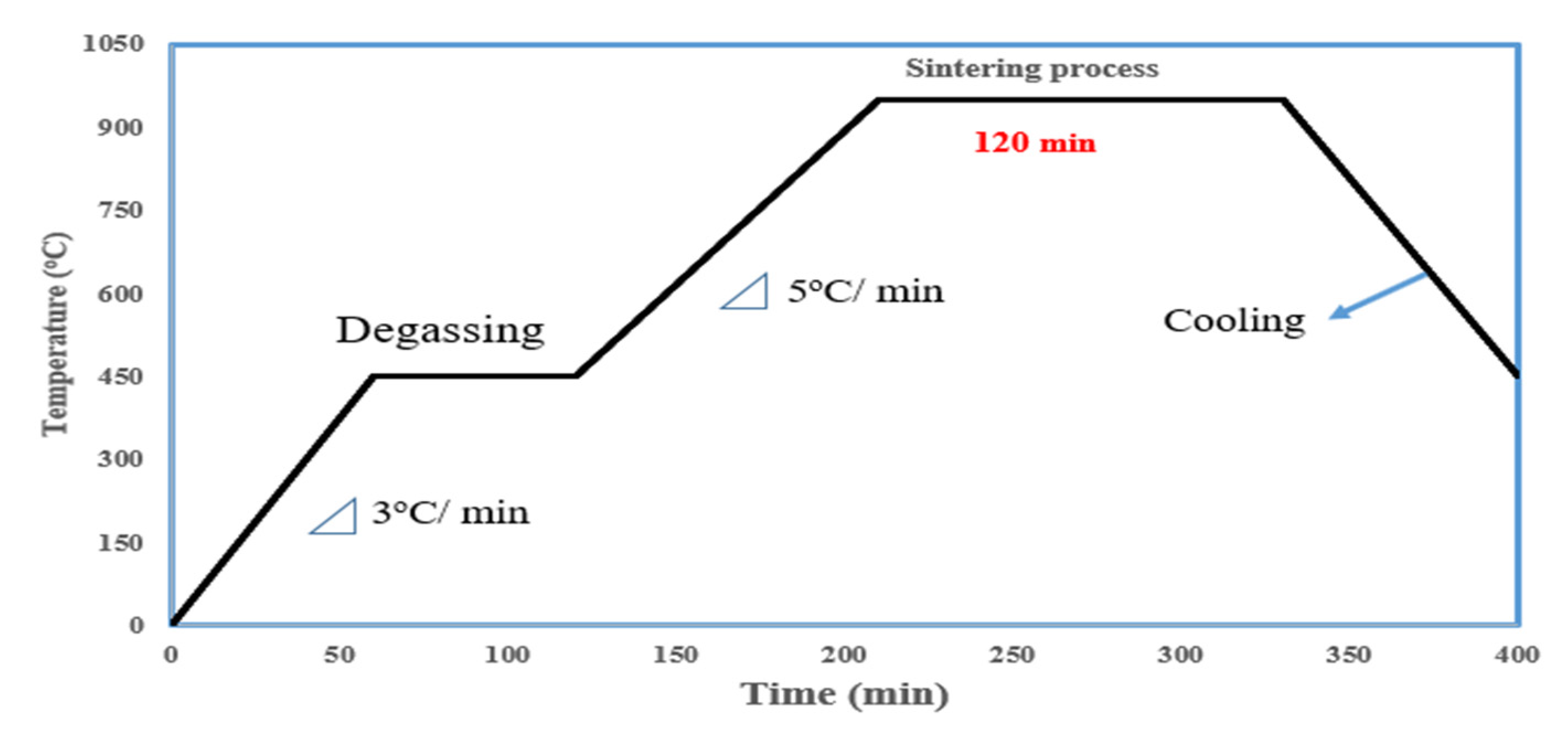
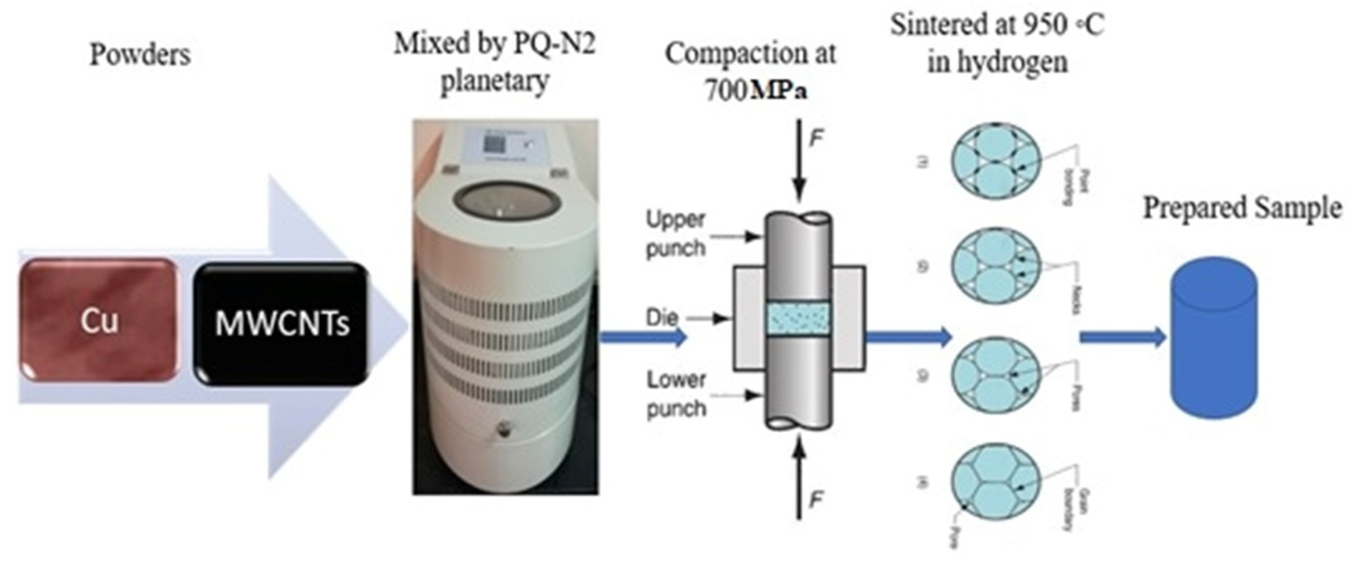
2. Materials and Methods

2.1. Materials

The experimental work was carried out in the laboratories of Technology and Education College, Beni-Suef University, and the Central Metallurgical Research and Development Institute (CMRDI) in Helwan, Egypt. Cu powder and MWCNTs were supplied by Algoumhoria Company for Chemicals Trade and Medicals (Cairo, Egypt). Table 1 shows the used materials and their characteristics. Cu powder and MWCNTs were used as the metal matrix and ceramic reinforcement, respectively, to produce the nanocomposite. Cu powders had an average particle size of 50 nm and a purity of 99.9%. MWCNTs were coated with nano Ag, using the electroless chemical deposition method to modify their interfacial properties. Ag was deposited onto the MWCNTs’ surface using the electroless method in two steps: sensitization and metallization. The sensitization step was applied to remove any contamination on MWCNTs’ surfaces by submerging them in a 5% sodium hydroxide solution. The MWCNT and sodium hydroxide mixture was stirred for 1.5 h. Then, it was dipped into acetone for 1.5 h and subjected to an ultrasonic cleaning process. After that, they were cleaned and washed with distilled water. Finally, they were dried in an electric furnace for 1 h at a temperature of 120 °C. The metallization step was applied to perform the deposition of nano Ag on MWCNTs using the electroless method by submerging them into a chemical bath composed of 3 g/L Ag nitrate and 300 mL/L formaldehyde. The pH of the bath was preserved at a reasonable value of ∼12 using an ammonia solution. The solution was subjected to a stirring processor for 15 min using a magnetic stirrer at room temperature to preserve the suspension of the MWCNTs in the solution. The reaction was accomplished in 45 min, and then the solution was cleaned and washed with acetone and dried in a vacuum furnace for 1.5 h at a temperature of 120 °C. Cu powder and 0.4, 0.8, or 1.2 wt.% MWCNTs were mixed and subjected to four grinding stations in a planetary ball mill (PQ-N2) at 300 rpm for 60 min, using a 10:1 ball-to-powder ratio to be more homogenous and remove any gathered powders. Then, the powder was cold-compacted at RT and subjected to a compacting pressure of 700 MPa in a uniaxial press. The compacted samples were sintered at 950 °C in hydrogen-inert gas for 2 h, using a heating cycle, shown in Figure 1. Figure 2 shows the preparation and fabrication process of the samples [23,24].

2.2. Powder Characterization

The prepared specimens were tested using an X-ray diffraction (XRD) instrument, a Bruker advanced X-ray diffractometer (model D8 Kristalloflex, Bruker, Germany); Ni-filtered Cu Ka radiation), which was used to assess the formation of phase transformation and the crystallite size of the powder. The powder’s microstructure was studied using scanning electron microscopy (JEOL-JSM 5410, Tokyo, Japan) with an energy dispersive spectrometer (EDS, Jeol, Tokyo, Japan) to study the particle size, morphology, shape, and agglomerations.

2.3. Relative Density Estimation

The measured (actual) density of the sintered specimen was calculated using Archimedes’ principle, according to the ASTM D1217 standard [25]. Relative density of the sintered specimen was tested using the Archimedes technique, using water as a floating liquid according to MPIF standard 42 [26]. The sintered samples were weighed in air and distilled water, then the density (Do) was calculated according to the equation:
Do = Wa/(Wa − Ww)
where Wa and Ww are the masses of the specimen in air and water, respectively. The theoretical density (Dth) of the investigated materials was calculated according to the equation:
1/Dth = (wt.% M/DM) + (wt.% R/DR)
where wt.% M and wt.% R are the weight fractions of matrix and reinforcement, respectively; and DM and DR are the densities of matrix and reinforcement, respectively. The relative density of the composite is the ratio of the measured (actual density) to the theoretical sintered density.

2.4. Electrical Resistivity and Thermal Conductivity Estimation

The electrical resistivity was measured using a PCE-COM20 electric resistivity instrument. Thermal conductivity was evaluated from the equation [27]:
K = LTσ
where K denotes the thermal conductivity in W/m, L = 2.45 × 10⁻⁸ W Ω K−2 denotes the Lorentz number for composites, T denotes the absolute temperature in K, and σ denotes the electrical conductivity in Ω−1 m−1.

2.5. Electrochemical Behavior and Corrosion Resistance of Cu-MWCNT Nanocomposites

The electrochemical behavior of the prepared nanocomposites was assessed using an electrochemical cell in which Cu-MWCNT nanocomposites were used as electrodes. We dipped the Cu-MWCNTs’ sintered samples in an electrolytic solution. A three-electrode cell was used in this test. Cu specimens with a 1 cm2 cross-sectional area were utilized as a working electrode, while platinum with a 1 cm2 cross-sectional area was used as a counter face electrode. All potential records were carried out using Ag−AgCl with +220 mV versus a reference electrode (standard hydrogen electrode). The electrolytic solution contained 0.05 M KNO3 and 0.1 M Zn (NO3)2. The counter and working electrodes were adjusted parallel to each other at a 0.4 cm distance. All Cu sheets were cleaned in an ultrasonic bath with distilled water and subsequently washed with ethyl alcohol. Cu-MWCNT nanocomposites were etched for 20 s with diluted HCL to eliminate the oxide beds. The specimens were first refined by emery SiC papers; next, they were immersed in HCL for 15 s and washed with distilled water. The cyclic voltammetric experiments were performed using a 10 mV/s scan rate and electrode potential (0–2000 mV) vs. a Ag−AgCl basic electrode. The curves of cyclic voltammetry were recorded using a potentiostat−galvanostat (20 V/1 A). The applied currents and potentials were monitored and evaluated using a Volta lab (model PGP 201, Paris, France). ZnO film deposits on Cu-MWCNT nanocomposites were washed with pure water and ethanol in a desiccator for 1 h. The working electrode for the corrosion investigation was the Cu-MWCNT specimen, while the counter face electrode was a Pt electrode. All electrodes were adjusted parallel to each other in a bath containing 0.1 M Zn (NO3)2 + 0.05 M KNO3. This was attained by immersing the tested Cu-MWCNT specimens in nitrate electrolyte for which a traditional three-electrode cell was utilized. The scan rate and starting potential range of the voltammogram were 10 mV/s and 0–2000 mV, respectively. The corrosion potential (Ecorr) and current density (Icorr) were displayed from the polarization figures of a Tafel analysis. The voltammetric data were obtained with the help of a potentiostat Volta Lab 21 PGP 201 model.

3. Results and Discussion

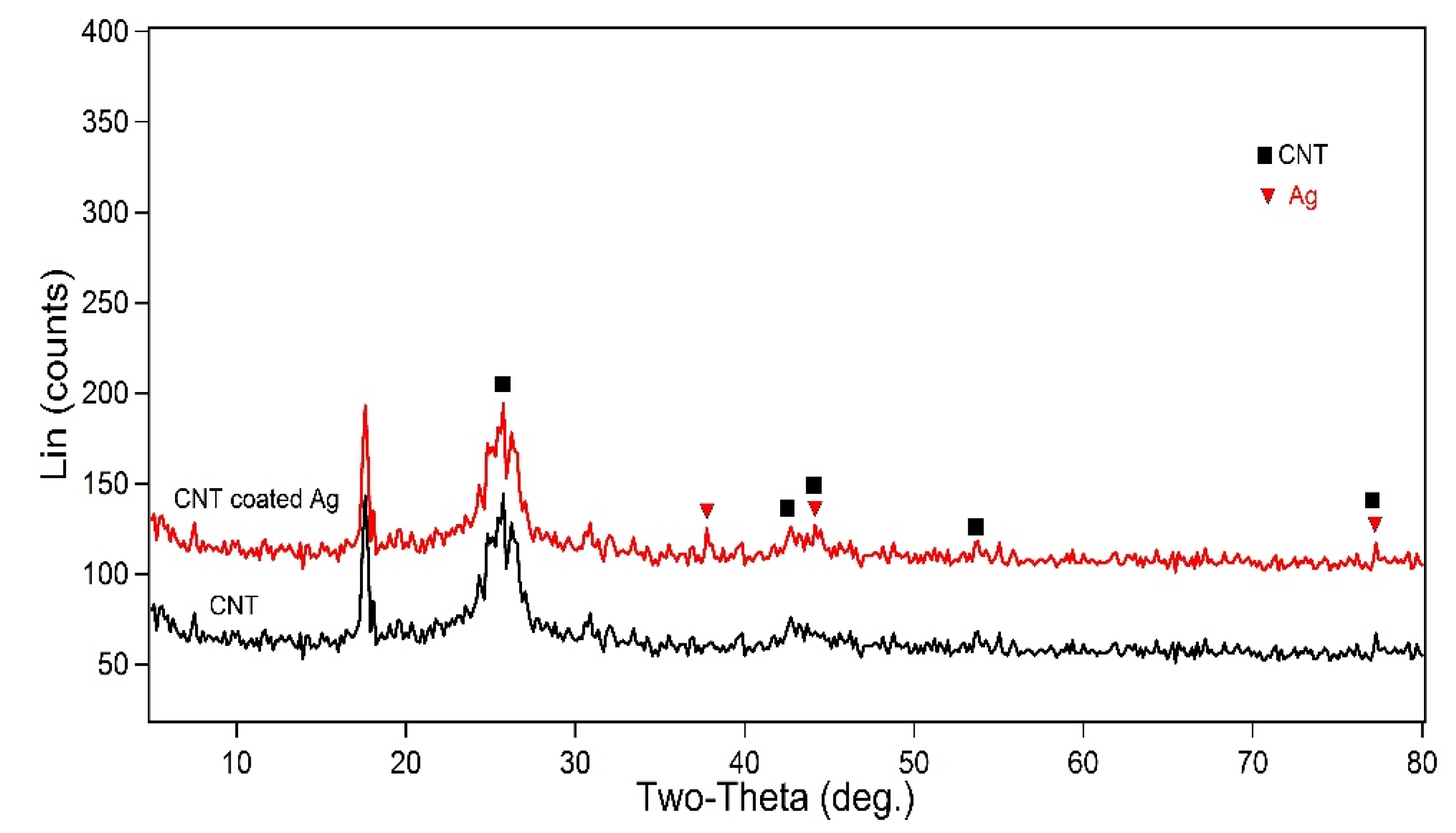
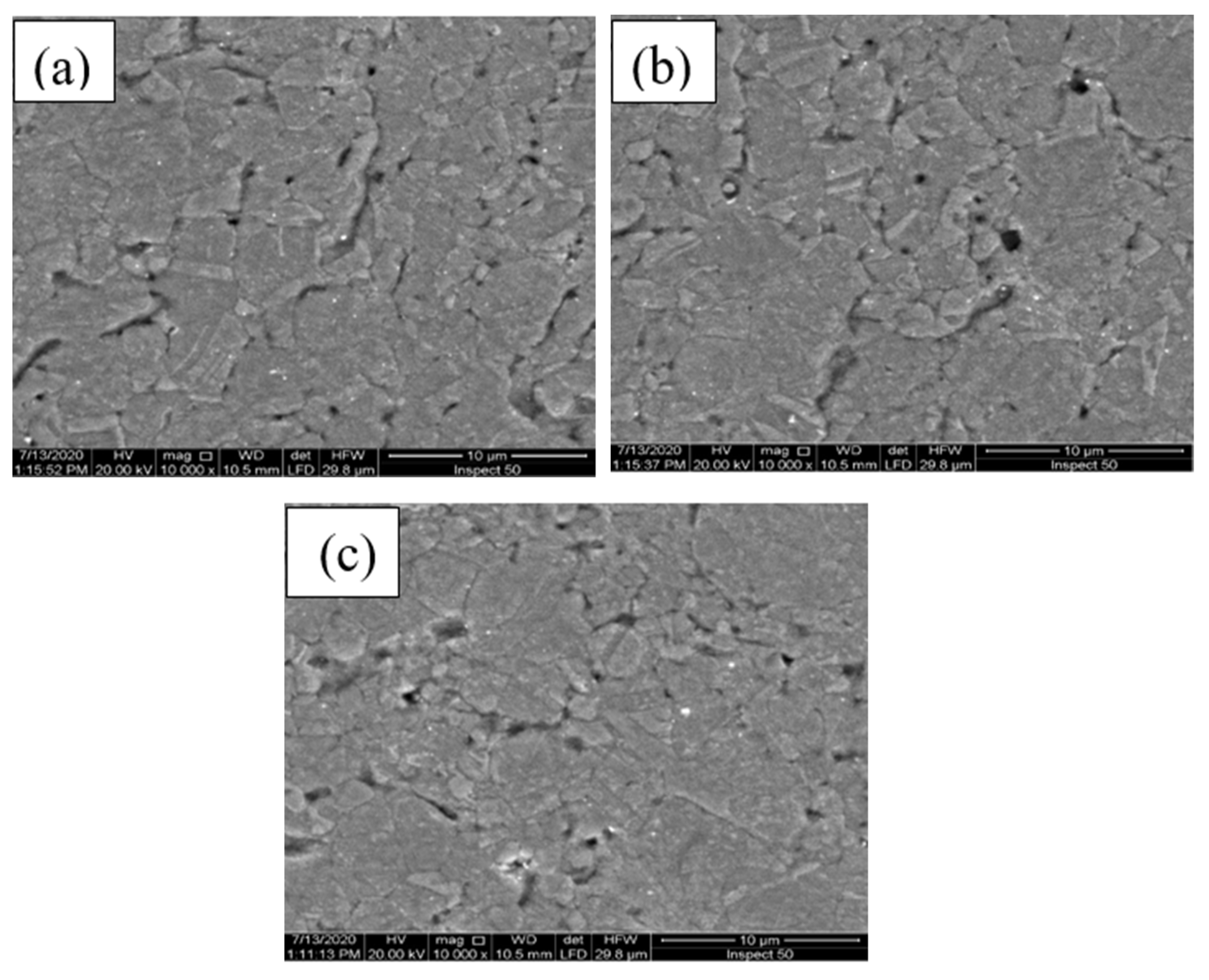
3.1. Microstructure Evolutions and PHASE structure

Figure 3 displays the XRD analysis of MWCNTs before and after coating with nano silver. The XRD profiles showed that there were two main peaks verifying the success of the electroless coating process of MWCNTs with Ag nanoparticles without any other undesirable compounds. No obvious peaks corresponding to silver carbide were observed after the coating process. With these coating process conditions, no significant reaction could take place between Ag and MWCNTs.
Figure 4 illustrates the SEM microstructure of Cu-MWCNT nanocomposites. There are three distinct regions: the first region is the bright region that represents the Cu matrix, the second region has a dark appearance that corresponds to the MWCNTs, and the third region is the Ag nanoparticles that coated the MWCNTs. The images presented in Figure 4 display the homogeneous and uniform dispersion of MWCNTs in the Cu matrix for the three prepared samples of Cu-MWCNT nanocomposites. As a result of coating the MWCNTs with Ag nanoparticles, the nonwettability problem between the ceramic MWCNTs and the metallic Cu was solved. The nano Ag layer decreased the surface energy between MWCNTs and Cu so that favorable homogeneity could occur. No agglomeration was detected and acceptable dispersion of CNTs in the Cu matrix was achieved, except for those samples with high MWCNT content, which had some aggregation that formed pores [28,29].

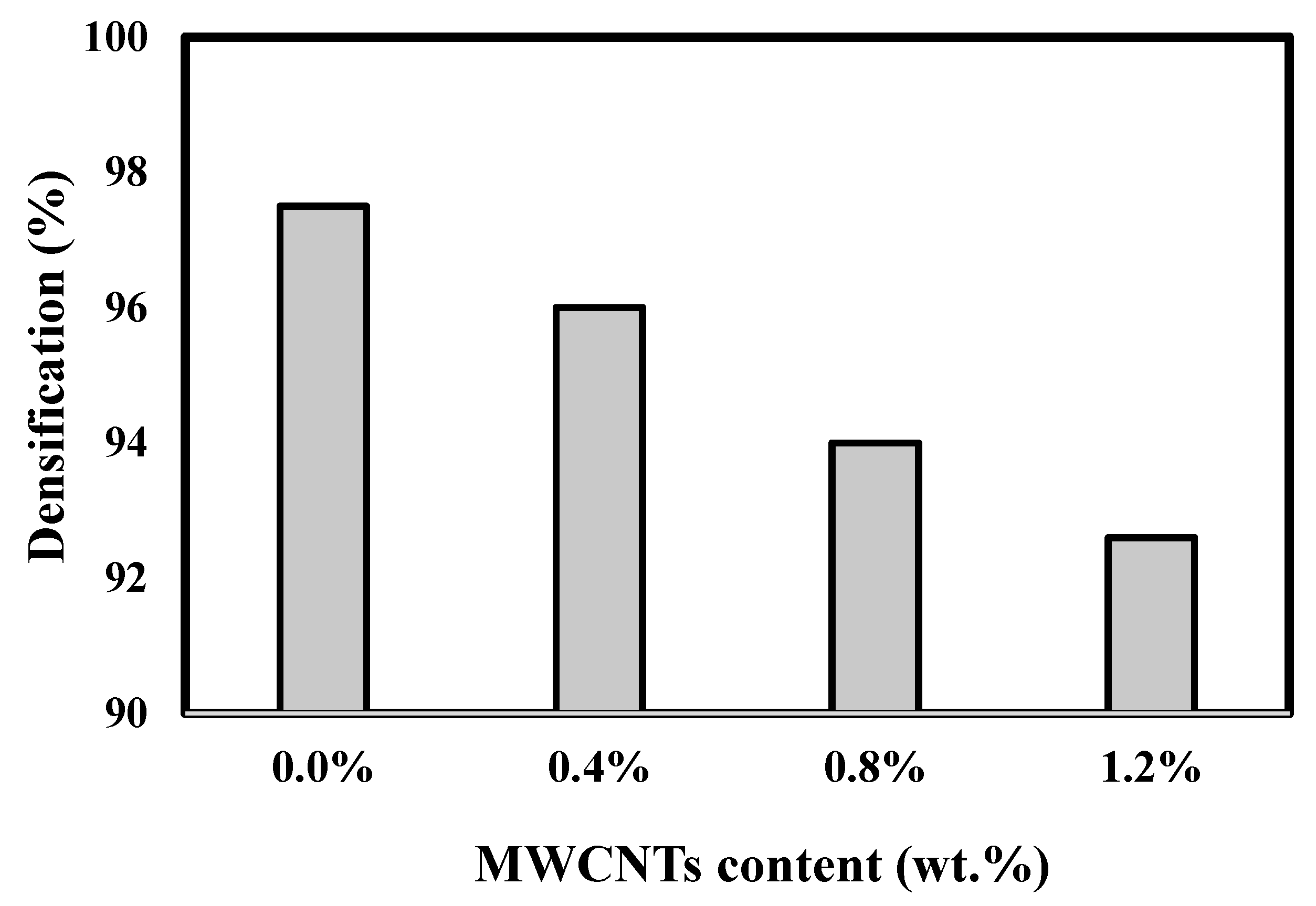
3.2. Relative Density Estimation

The influence of MWCNT content on the relative density of the Cu matrix is demonstrated in Figure 5. Relative density was calculated using the following equation:
R D = A D T h D
where, RD, AD, and ThD are the relative density, actual density, and theoretical density, respectively. Table 2 displays the relative density of Cu-MWCNTs. The actual density was measured using the Archimedes technique, but the theoretical density was measured using the mixtures rule. The figure displays that increasing the content of MWCNT nanoparticles resulted in a decreased amount of relative density, as the density of MWCNTs is lower than that of Cu (2.2 and 8.9 g/cc, respectively). In dispersing light materials such as CNTs in a homogenous manner in a heavier matrix, the overall density decreases. By increasing the MWCNTs’ percentage, some agglomeration took place, which caused the formation of internal voids that decreased the density.
The electrical conductivity of Cu reinforced with MWCNTs coated with 5 wt.% nano Ag is presented in Figure 6. Table 3 displays the electrical resistivity and thermal conductivity of Cu reinforced with MWCNTs. The results reveal a considerable decrease in the electrical conductivity value by increasing the MWCNTs’ ratio. This may have been caused by the lower electrical conductivity of MWCNTs compared to Cu. In addition, the formation of pores by increasing the MWCNTs’ percentage is another factor that decreased the electrical conductivity. The presence of pores restricts the motion of electrons so that conductivity decreases. However, it must be noted that the electrical resistivity values increased slightly because, for the pure copper sample, it was ~1.8 µΩ·cm, while for 1.2 wt.% MWCNTs, it increased up to only ~2.5 µΩ·cm. This is an indication of the still favorable electrical conductivity of Cu-MWCNT nanocomposites. This may be explained by the relatively acceptable electrical conductivity of MWCNTs and the high conductivity of nano silver, which has a higher electrical conductivity than Cu [30,31]. Figure 7 shows the effect of MWCNTs on the thermal conductivity of Cu-MWCNT nanocomposites. The figure shows a gradual decrease in the thermal conductivity achieved by increasing MWCNTs’ percentage. This is due to the lower thermal conductivity of CNTs than that of Cu. Additionally, as the CNTs’ ratio increased, some aggregation took place, leading to the formation of pores and internal voids, which have zero conductivity and caused a decrease in the overall thermal conductivity of the fabricated nanocomposites. One can observe that a slight decrease in the thermal conductivity due to the presence of conductive nano materials, such as MWCNTs and nano silver, dispersed in the Cu matrix. The thermal conductivity of pure Cu is about 380 W/M·K, while that of 1.2 wt.% MWCNTs is ~270 W/M·K and that of 0.4 wt.% MWCNTs is ~360 W/M·K.

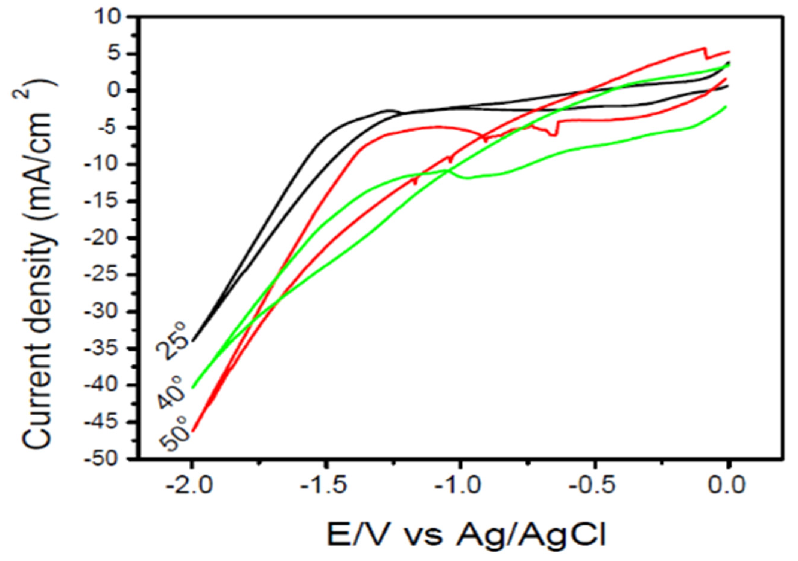
3.3. The Corrosion Resistance and Electrochemical Behavior of the Prepared Nanocomposites

Figure 8 shows the relation between potential and current density for the measured pure Cu. Three cyclic voltammetric curves were recorded on Cu cathode in a 0.05 M KNO3 + 0.1 M Zn (NO3)2 solution with the three tested bath temperatures, namely 25, 40, and 50 °C. The reported voltammogram of 25 °C indicated that a current of −10 mA cm−2 was recorded at −1.1 V for the cathode deposition current. Furthermore, the current density of deposition increased up to −35 mA/cm2 at −1.3 V.
Figure 9 represents the cyclic voltammogram (CV) of the four fabricated Cu-MWCNT nanocomposites with 0, 0.4, 0.8, and 1.2 wt.% MWCNTs. Curves A and B show an identical behavior of pure Cu and the 0.4 wt.% MWCNTs with a cathodic current density of −47 mA·cm−2. We observed that the 0.4 wt.% MWCNTs had no effect on the recorded voltammogram curve. This may be due to the negligible effect of the 0.4 wt.% MWCNTs on the cathodic current density of the sample. For the 0.8 wt.% MWCNTs, the cathodic current density increased and promoted ZnO film deposition.
The voltammogram shows that the deposition of ZnO started at −1 V potential, then after a −1300 mV potential, a sharp increase in the cathodic current density occurred up to −70 Ma·cm−2, which is related to the evolution of hydrogen gas and the reduction of nitrate ions. For the 1.2 wt.% MWCNTs, which are represented by the cyclic voltammogram D, ZnO film deposition began at a −0.9 V cathodic potential, lower than that of pure Cu, and the cathode potential related to the hydrogen gas evaluation was recorded at ~−1350 mV with current −110 mA·cm−2. From the above results, it is clear from Figure 9 that as the MWCNTs’ percentage increased, the deposition of ZnO film became easier with a lower potential. The maximum current density was −110 Ma·cm−2 for the 1.2 wt.% MWCNT samples. Each fabricated nanocomposite had its own potential energy and electrical conductivity, so the deposition of ZnO film was affected by the electrical conductivity of the samples and the porosity percentage. Although the conductivity decreased slightly by increasing the MWCNTs’ ratio, there is another factor, which is the increase in porosity percentage, where the presence of pores made a small electrochemical cell on the substrate surface that promoted the deposition process of ZnO thin film.
The corrosion behavior of the manufactured Cu-MWCNT nanocomposites was studied. The corrosion behavior of samples was determined using a 0.05 M KNO3 + 0.1M Zn(NO3)2 bath with the same above considerations. The polarization resistance (Rp) is defined as the transition resistance between a copper electrode and electrolyte. Table 4 displays the resistance polarization and corrosion rate of Cu reinforced with MWCNTs. The relation between the MWCNTs’ percentage and the polarization resistance is illustrated in Figure 10. High Rp values of a metal electrode indicate a high corrosion resistance and low values reflect a low corrosion resistance. Therefore, polarization resistance is computed as the ratio between the applied potential and the current response. This type of resistance is inversely proportional to the corrosion rate. The parameters of corrosion current, polarization resistance, and rate of corrosion are important for examining the corrosion behavior of a copper matrix reinforced with MWCNTs. Figure 10 illustrates the resistance polarization curve of Cu-MWCNT specimens prepared in a 0.05 M KNO3 + 0.1M Zn(NO3)2 bath at 50 °C. The results revealed that raising the MWCNTs’ percentage in copper specimens from 0 to 0.4 wt.% increased the resistance polarization values. The resistance polarization increased gradually by increasing MWCNTs’ percentage and attained the highest value of 115 ohms·cm2 for the 1.2 wt.% MWCNTs. This may be explained by the favorable dispersion of MWCNTs in the copper matrix because it is a ceramic material that has a naturally high corrosion resistance. In addition, coating them with the nano silver layer improved the adhesion and homogeneity with Cu, so the copper corroded more by reinforcing with MWCNTs [32].
Figure 11 displays the effect of the MWCNTs’ percentage on the rate of corrosion of reinforced Cu specimens in the bath containing 0.05 M KNO3 + 0.1 M Zn(NO3)2. The corrosion rate gradually changed with increasing MWCNTs’ percentage in the Cu- MWCNT electrode samples. The corrosion rate increased up to 0.4 wt.% MWCNTs. This may be attributed to the lower porosity of the 0.4 wt.% MWCNT sample and the lower electrical resistivity. The presence of pores gave the corrosive solution the chance to enter the sintered samples and corrode the sample. Additionally, the internal pores acted as an active center for the corrosion reaction. On the other hand, the corrosion rate decreased with increasing MWCNTs from 0.8 to 1.2 wt.% and reached its lowest value of 3.08 mm/year with 2.997 mm/year of free sample.

4. Conclusions

A Cu matrix was reinforced with nanostructured MWCNTs using electroless deposition followed by PM. MWCNTs with weight fractions of 0.4, 0.8, and 1.2 wt.% were added to the Cu matrix. The properties of the Cu matrix, including microstructure, thermal conductivity, density, rate of corrosion, electrical resistivity, and electrochemical behavior, were investigated. The following conclusions can be drawn:
  • MWCNTs were coated with Ag nanoparticles by electroless deposition. The microstructure indicated that MWCNTs were distributed homogenously in the Cu matrix.
  • The matrix density was reduced by raising the MWCNT nanocomposites’ content.
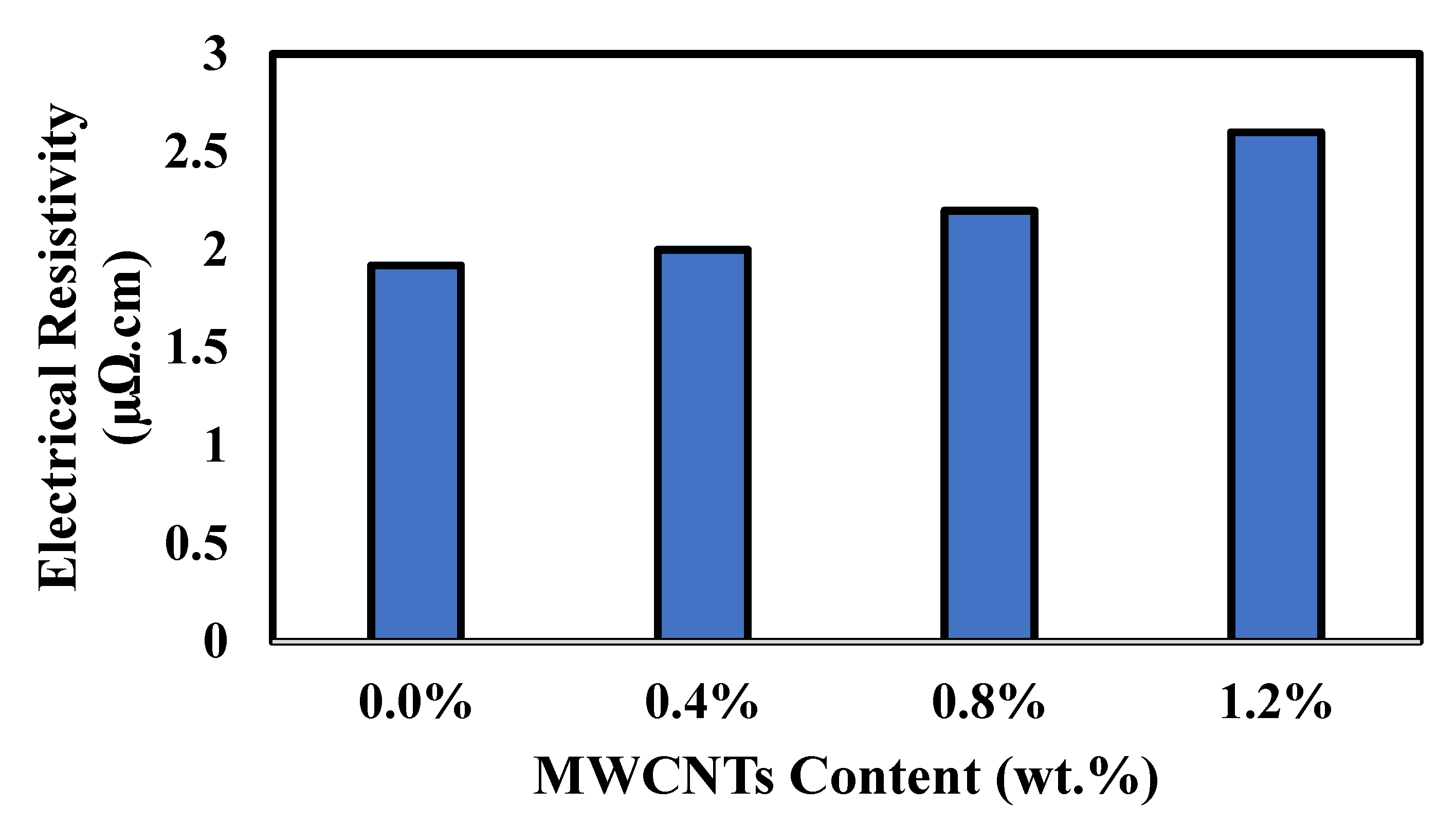
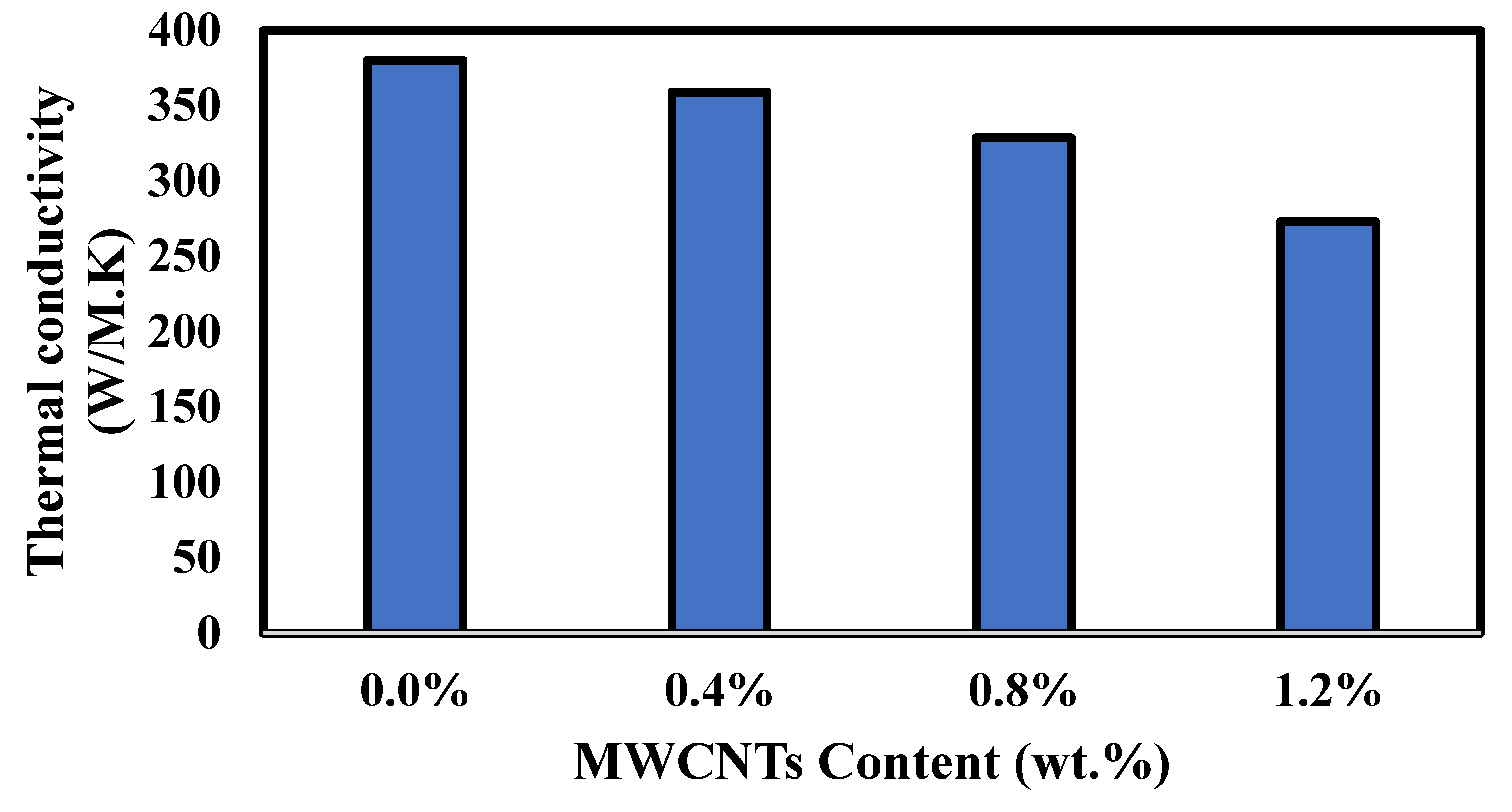
  • Electrical resistivity gradually increased by adding MWCNTs to the Cu nanocomposite, while thermal conductivity decreased by increasing MWCNTs in the Cu nanocomposites.
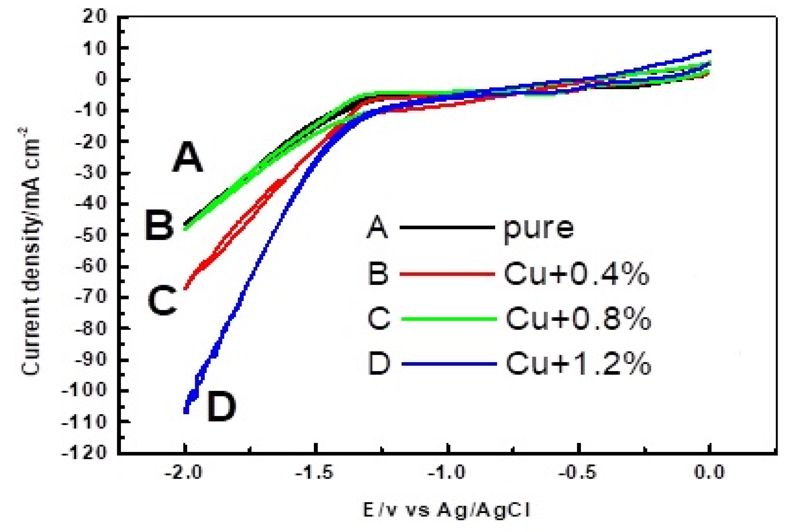
  • The maximum current density was 110 mA·cm−2 for the 1.2 wt.% MWCNTs.
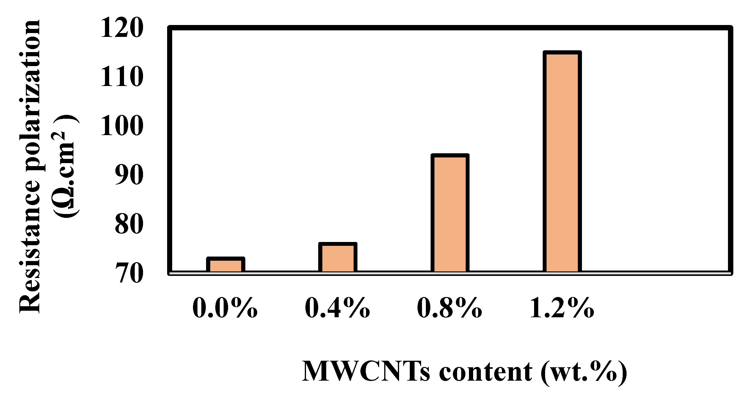
  • The maximum resistance polarization was 115 Ω·cm2 for the 1.2 wt.% MWCNTs.
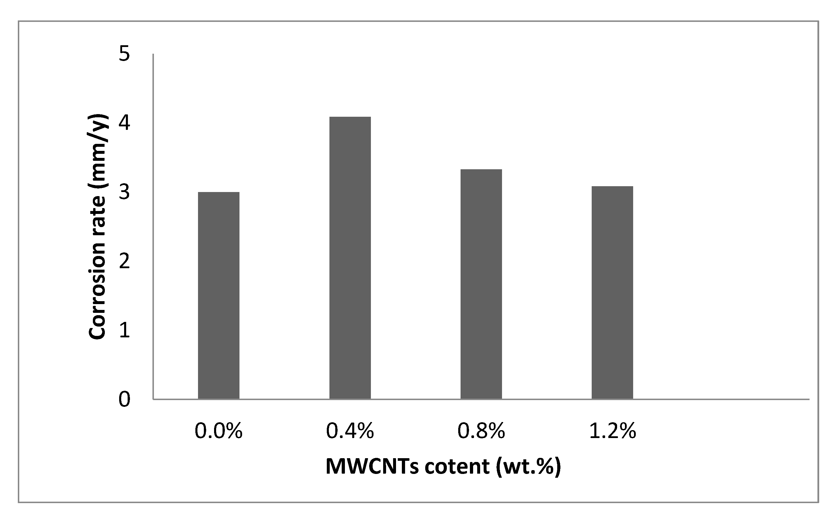
  • The rate of corrosion declined for the 1.2 wt.% MWCNTs and reached its lowest value of 3.08 mm/year.

Author Contributions

Data curation, E.M.E. and N.A.A.; Formal analysis, F.A.E. and M.A.; Investigation, M.M.M. and A.H.E.; Methodology, O.A.E.-K.; Project administration, J.D. All authors have read and agreed to the published version of the manuscript.

Funding

This research was funded by the Deanship of Scientific Research at Imam Mohammad Ibn Saud Islamic University.

Institutional Review Board Statement

Not applicable.

Informed Consent Statement

Not applicable.

Data Availability Statement

All data are included in the manuscript.

Acknowledgments

The authors extend their appreciation to the Deanship of Scientific Research at Imam Mohammad Ibn Saud Islamic University for funding this work through Research Group No. RG-21-12-01.

Conflicts of Interest

The authors declare no conflict of interest.

References

  1. Zhou, H.; Wu, C.; Tang, D.Y.; Shi, X.; Xue, Y.; Huang, Q.; Zhang, J.; Elsheikh, A.H.; Ibrahim, A.M.M. Tribological Performance of Gradient Ag-Multilayer Graphene/TC4 Alloy Self-Lubricating Composites Prepared By Laser Additive Manufacturing. Tribol. Trans. 2021, 64, 819–829. [Google Scholar] [CrossRef]
  2. Elsheikh, A.H.; Abd Elaziz, M.; Ramesh, B.; Egiza, M.; Al-qaness, M.A.A. Modeling of drilling process of GFRP composite using a hybrid random vector functional link network/parasitism-predation algorithm. J. Mater. Res. Technol. 2021, 14, 298–311. [Google Scholar] [CrossRef]
  3. Thangaraj, M.; Ahmadein, M.; Alsaleh, N.A.; Elsheikh, A.H. Optimization of abrasive water jet machining of SiC reinforced aluminum alloy based metal matrix composites using Taguchi–DEAR technique. Materials 2021, 14, 6250. [Google Scholar] [CrossRef] [PubMed]
  4. Elsheikh, A.H.; Panchal, H.; Shanmugan, S.; Muthuramalingam, T.; El-Kassas, A.M.; Ramesh, B. Recent progresses in wood-plastic composites: Pre-processing treatments, manufacturing techniques, recyclability and eco-friendly assessment. Clean. Eng. Technol. 2022, 8, 100450. [Google Scholar] [CrossRef]
  5. Ahmadein, M.; El-Kady, O.A.; Mohammed, M.M.; Essa, F.A.; Alsaleh, N.A.; Djuansjah, J.; Elsheikh, A.H. Improving the mechanical properties and coefficient of thermal expansion of molybdenum-reinforced copper using powder metallurgy. Mater. Res. Express 2021, 8, 096502. [Google Scholar] [CrossRef]
  6. Elsheikh, A.H.; Yu, J.; Sathyamurthy, R.; Tawfik, M.M.; Shanmugan, S.; Essa, F.A. Improving the tribological properties of AISI M50 steel using Sns/Zno solid lubricants. J. Alloys Compd. 2020, 821, 153494. [Google Scholar] [CrossRef]
  7. Essa, F.A.; Yu, J.; Elsheikh, A.H.; Tawfik, M.M. A new M50 matrix composite sintered with a hybrid Sns/Zno nanoscale solid lubricants: An experimental investigation. Mater. Res. Express 2019, 6, 116523. [Google Scholar] [CrossRef]
  8. Miracle, D. Metal matrix composites–from science to technological significance. Compos. Sci. Technol. 2005, 65, 2526–2540. [Google Scholar] [CrossRef]
  9. Dorri Moghadam, A.; Schultz, B.F.; Ferguson, J.; Omrani, E.; Rohatgi, P.K.; Gupta, N. Functional metal matrix composites: Self-lubricating, self-healing, and nanocomposites-an outlook. Jom 2014, 66, 872–881. [Google Scholar] [CrossRef]
  10. Khoshaim, A.B.; Moustafa, E.B.; Bafakeeh, O.T.; Elsheikh, A.H. An Optimized Multilayer Perceptrons Model Using Grey Wolf Optimizer to Predict Mechanical and Microstructural Properties of Friction Stir Processed Aluminum Alloy Reinforced by Nanoparticles. Coatings 2021, 11, 1476. [Google Scholar] [CrossRef]
  11. Chen, L.; Hou, Z.; Liu, Y.; Luan, C.; Zhu, L.; Li, W. High strength and high ductility copper matrix composite reinforced by graded distribution of carbon nanotubes. Compos. Part A Appl. Sci. Manuf. 2020, 138, 106063. [Google Scholar] [CrossRef]
  12. Zhang, L.; He, X.; Qu, X.; Duan, B.; Lu, X.; Qin, M. Dry sliding wear properties of high volume fraction SiCp/Cu composites produced by pressureless infiltration. Wear 2008, 265, 1848–1856. [Google Scholar] [CrossRef]
  13. Maji, P.; Dube, R.; Basu, B. Enhancement of wear resistance of copper with tungsten addition (≤20 wt%) by powder metallurgy route. J. Tribol. 2009, 131, 041602. [Google Scholar] [CrossRef]
  14. Oseli, A.; Vesel, A.; Mozetič, M.; Žagar, E.; Huskić, M.; Slemenik Perše, L. Nano-mesh superstructure in single-walled carbon nanotube/polyethylene nanocomposites, and its impact on rheological, thermal and mechanical properties. Compos. Part A Appl. Sci. Manuf. 2020, 136, 105972. [Google Scholar] [CrossRef]
  15. Zheng, Z.; Yang, A.; Tao, J.; Li, J.; Zhang, W.; Li, X.; Xue, H. Mechanical and Conductive Properties of Cu Matrix Composites Reinforced by Oriented Carbon Nanotubes with Different Coatings. Nanomaterials 2022, 12, 266. [Google Scholar] [CrossRef]
  16. Kang, D.; Hwang, S.; Jung, B.; Shim, J. Characterizations of polypropylene/single-walled carbon nanotube nanocomposites prepared by the novel melt processing technique with a controlled residence time. Processes 2021, 9, 1395. [Google Scholar] [CrossRef]
  17. Lozovyi, F.; Ivanenko, K.; Nedilko, S.; Revo, S.; Hamamda, S. Thermal analysis of polyethylene + X% carbon nanotubes. Nanoscale Res. Lett. 2016, 11, 97. [Google Scholar] [CrossRef] [PubMed] [Green Version]
  18. Arai, S.; Osaki, T. Fabrication of copper/multiwalled carbon nanotube composites containing different sized nanotubes by electroless deposition. J. Electrochem. Soc. 2014, 162, D68. [Google Scholar] [CrossRef] [Green Version]
  19. Chu, K.; Jia, C.-c.; Li, W.-s. Thermal conductivity enhancement in carbon nanotube/Cu–Ti composites. Appl. Phys. A 2013, 110, 269–273. [Google Scholar] [CrossRef]
  20. Chu, K.; Jia, C.; Guo, H.; Li, W. On the thermal conductivity of Cu–Zr/diamond composites. Mater. Des. 2013, 45, 36–42. [Google Scholar] [CrossRef]
  21. Cho, S.; Kikuchi, K.; Kawasaki, A. On the role of amorphous intergranular and interfacial layers in the thermal conductivity of a multi-walled carbon nanotube–copper matrix composite. Acta Mater. 2012, 60, 726–736. [Google Scholar] [CrossRef]
  22. Firkowska, I.; Boden, A.; Vogt, A.-M.; Reich, S. Effect of carbon nanotube surface modification on thermal properties of copper–CNT composites. J. Mater. Chem. 2011, 21, 17541–17546. [Google Scholar] [CrossRef]
  23. Fathy, A.; Sadoun, A.; Abdelhameed, M. Effect of matrix/reinforcement particle size ratio (PSR) on the mechanical properties of extruded Al–SiC composites. Int. J. Adv. Manuf. Technol. 2014, 73, 1049–1056. [Google Scholar] [CrossRef]
  24. Shehata, F.; Fathy, A.; Abdelhameed, M.; Moustafa, S. Preparation and properties of Al2O3 nanoparticle reinforced copper matrix composites by in situ processing. Mater. Des. 2009, 30, 2756–2762. [Google Scholar] [CrossRef]
  25. ASTM, D. 1217. Standard Test Method for Density and Relative Density (Specific Gravity) of Liquids by Bingham Pycnometer; Annual Book of ASTM Standards: West Conshohocken, PA, USA, 2007; ASTM-D1217-20. [Google Scholar]
  26. Samal, P.; Newkirk, J. Materials Standards and Test Method Standards for Powder Metallurgy. ASM Handb. 2015, 7, 45–51. [Google Scholar]
  27. Fathy, A.; El-Kady, O. Thermal expansion and thermal conductivity characteristics of Cu–Al2O3 nanocomposites. Mater. Des. 2013, 46, 355–359. [Google Scholar] [CrossRef]
  28. Lee, D.; Kim, B. Nanostructured Cu–Al2O3 composite produced by thermochemical process for electrode application. Mater. Lett. 2004, 58, 378–383. [Google Scholar] [CrossRef]
  29. Barakat, W.; Wagih, A.; Elkady, O.A.; Abu-Oqail, A.; Fathy, A.; El-Nikhaily, A. Effect of Al2O3 nanoparticles content and compaction temperature on properties of Al–Al2O3 coated Cu nanocomposites. Compos. Part B Eng. 2019, 175, 107140. [Google Scholar] [CrossRef]
  30. Ling, G.; Li, Y. Influencing factors on the uniformity of copper coated nano-Al2O3 powders prepared by electroless plating. Mater. Lett. 2005, 59, 1610–1613. [Google Scholar] [CrossRef]
  31. Rajkovic, V.; Bozic, D.; Jovanovic, M.T. Effects of copper and Al2O3 particles on characteristics of Cu–Al2O3 composites. Mater. Des. 2010, 31, 1962–1970. [Google Scholar] [CrossRef]
  32. Elsayed, E.; Harraz, F.; Saba, A. Nanocrystalline zinc oxide thin films prepared by electrochemical technique for advanced applications. Int. J. Nanoparticles 2012, 5, 136–148. [Google Scholar] [CrossRef]
Figure 1. The heating cycle of the sintered sample at 950 °C in hydrogen-inert gas.
Coatings 12 00409 g001
Figure 2. The preparation and fabrication process of the samples.
Coatings 12 00409 g002
Figure 3. XRD lines of MWCNTs with and without Ag coating.
Coatings 12 00409 g003
Figure 4. SEM micrograph of (a) 0.4, (b) 0.8, and (c) 1.2 wt.% MWCNT content on Cu nanocomposites.
Coatings 12 00409 g004
Figure 5. Density of MWCNT content on Cu nanocomposites.
Coatings 12 00409 g005
Figure 6. Electrical resistivity of MWCNT content on Cu nanocomposites.
Coatings 12 00409 g006
Figure 7. Thermal conductivity of MWCNT content on Cu nanocomposites.
Coatings 12 00409 g007
Figure 8. The cyclic voltammograms on pure Cu.
Coatings 12 00409 g008
Figure 9. Cyclic voltammograms of Cu with different MWCNT contents.
Coatings 12 00409 g009
Figure 10. Resistance polarization of Cu-MWCNT nanocomposites.
Coatings 12 00409 g010
Figure 11. Corrosion rate of Cu-MWCNT nanocomposites.
Coatings 12 00409 g011
Table 1. The used materials and characteristics of Cu-MWCNTs.
PowderPurity %Particle Size (nm)Particle ShapeDensity (g/cm3)
Cu99.99~50Spherical8.94
MWCNTs99.97~50Tube0.7~1.7
Table 2. The relative density of Cu-MWCNTs.
SamplePercent (wt.%)Relative Density
Cu pure10097.5
MWCNTs0.496
MWCNTs0.894
MWCNTs1.292.6
Table 3. The electrical resistivity and thermal conductivity of Cu reinforced with MWCNTs.
SamplePercent
(wt.%)
Resistance R (Ω)Height (mm)Area = T.W (mm2)Electrical
Resistivity
ρ = (µΩ·cm)
Thermal Conductivity
K = σ.L.T (W.m−1/K)
Cu Pure1000.000000694.061131.92380
MWCNTs0.40.000000951132.01359
MWCNTs0.80.00000115.61132.2329
MWCNTs1.20.00000135.51132.6273
Table 4. The resistance polarization and corrosion rate of Cu reinforced with MWCNTs.
SamplePercent (wt.%)Resistance Polarization (Ω·cm2)Corrosion Rate (mm/y)
Cu Pure100734.5
MWCNTs0.4764
MWCNTs0.8943.328
MWCNTs1.21153.08
Publisher’s Note: MDPI stays neutral with regard to jurisdictional claims in published maps and institutional affiliations.

