Article

Wear Properties of Iron-Based Alloy Coatings Prepared by Plasma Transfer Arc Cladding

1
School of Materials and Chemical Engineering, Xi’an Technological University, Xi’an 710021, China
2
Shaanxi Province Engineering Research Centre of Aluminum/Magnesium Light Alloy and Composites, Xi’an 710021, China
3
Shanxi Disel Engine Co., Ltd., Datong 035600, China
*
Authors to whom correspondence should be addressed.
Coatings 2022, 12(2), 243; https://doi.org/10.3390/coatings12020243
Submission received: 30 December 2021 / Revised: 24 January 2022 / Accepted: 10 February 2022 / Published: 13 February 2022

Abstract

:
Plasma transfer arc cladding technology has been widely utilized in surface engineering, repairing and remanufacturing. In the present work, multiple cladded thick claddings were prepared on compacted graphite cast iron (CGI) substrates with iron-based powders through plasma transfer arc cladding technology using different plasma arc currents to improve the surface wear resistance. The coatings’ phase and microstructure were analysed through XRD, SEM and EDS. The coatings’ microhardness and wear resistance were characterized. There were pearlite, graphite, austenite and secondary carbides in the iron-based alloy coatings. Due to the heat influence during the multiple cladding process, a spheroidal graphite transition zone appeared between the substrate and the coating. The microhardness of the claddings varied from 363 to 402 HV as the plasma arc current was changed from 45 to 60 A. With the increase of plasma arc current, the cladding’s microhardness increased. The iron-based coating’s minimum friction coefficient and wear mass loss were about 0.48 and 4.2 mg, respectively, when the plasma arc current was 60 A, which are lower values than those of the compacted graphite iron substrate with the friction coefficient and wear mass loss of 0.55 and 8.2 mg. Compared with the substrate, the iron-based alloy claddings achieved the effect of reducing friction and wear resistance simultaneously, which resulted from the self-lubricating effect of graphite and high wear-resistance of carbides in the claddings. The iron-based coatings had a similar abrasive wear mechanism to the CGI, which should be helpful to repair or remanufacture CGI workpieces.

1. Introduction

Compacted graphite cast iron (CGI) is commonly used in the automotive and heavy engineering industrial fields for its comprehensive excellent properties as compared to grey cast iron and ductile cast iron [1,2,3]. Wear often occurs in these engineering parts, especially for moving parts, where it becomes the predominant cause of failure [4,5,6]. An effective way to repair and remanufacture failed parts and prolong the components’ useful life is to fabricate a coating to enhance its surface characteristics [7,8,9].
Plasma cladding has the advantages of strong metallurgical bonding, high efficiency and low dilution rate so it is seen as one of the most effective surface treatment means, being widely applied in surface modification in part repair and remanufacture [10,11,12,13]. Compared with high velocity oxygen-fuel (HVOF) and plasma spraying [14,15,16], plasma cladding can deposit a metallurgically-bonded thick coating on the substrate. During the plasma cladding process, part of the substrate surface is remelted and comixed with the melted feedstocks and then they solidify together, resulting in good metallurgical adhesion between the substrate and coating. Meanwhile, plasma cladding is more attractive than laser cladding in industrial applications for its relatively low cost and high efficiency [17,18,19].
Iron-based alloys are chosen as remanufacturing materials on the surface of cast irons without expensive metals, such as Ni, Co and Cr, for their good ductility and low cost. However, the poor tribological properties of iron-based coatings preclude their wide application [20,21]. As a result ceramic reinforced phases are introduced into iron-based coatings to improve the coating’s wear resistance properties. In Lyu’s work, Fe-based alloys coating with B4C particles as strengthening phase were deposited on Q235 steel through PTA [22]. During plasma cladding, B4C particles dissolved after they were fed centrally into the plasma flame, and cementite was generated. The Fe-based coating’s wear rate was 1/8 that of the Q235 substrate for the edge-injected B4C particles. Zhou et al. [23] investigated the influence of laser remelting on the microstructure and properties of WC/Fe-based amorphous composite coatings. The cracks and pores in the original coating could be eliminated through laser remelting so that the coating’s microhardness was also improved with no complete WC particles were retained. During the remelting process, WC particles dissolved into matrix phase absolutely. Fan et al. added spherical WC particles into Fe-based coatings on the surface of 304 stainless steel samples through PTA [24]. The Fe-based coating’s microhardness and wear resistance were increased greatly with the increase of WC contents. Compared with pure iron-based coatings, the main wear mechanisms of ceramic strengthened iron-based coatings were adhesive and two-body abrasive wear. Furthermore, the coating containing 60 wt.% of WC had three-body abrasion wear as the main wear form. However, ceramic reinforced iron-based coatings are much more expensive than iron-based alloys and the unmelted ceramic particles in the coating will be peeled off under wear conditions, resulting in a three-body abrasion process which would make the wear worse.
Compared with crystalline materials, amorphous materials have no crystal defects, including grain boundaries and dislocations, so that they exhibit high hardness and good corrosion resistance and wear resistance [25,26,27]. Cao et al. [28] prepared Fe-based amorphous coatings on stainless steel through laser cladding. The coatings’ microhardness was improved with the increase of the amorphous phase and the in-situ precipitated nanocrystalline material. Slight adhesive wear was the main wear mechanism of the coating. Sun et al. prepared FeBSiNb amorphous coatings on carbon steel through broad-beam laser cladding with amorphous alloy powders [29]. The FeBSiNb coating was mainly composed of α-Fe phase and precipitated Fe2B phase. The Nb-B particles generated in-situ were scattered evenly in the coatings, which enhanced the mechanical properties and significantly increased the wear resistance. Under the same test conditions, FeBSiNb coatings had much better wear resistance than the substrate, with a minimum wear rate of 1.42 × 10⁻⁵ mm3/(N·m). Nowadays the Fe-based amorphous materials used for coating preparation usually have a specific composition with strong glass-forming ability [30]. Commercially available Fe-based amorphous systems are often made up of the main elements (Fe, Co, Cr, Ni), small atom elements (B, C, Si, P) and big atom elements (W, Mo, Nb, Y, Zr) [31]. Amorphous materials cost a lot. Meanwhile, their engineering applications are limited by their room-temperature brittleness and restricted glass-forming ability [32]. Therefore, a designed iron-based alloy powder with a relatively low cost and intensive solid solution strengthening during the coating deposition as well as good compatibility with iron metal would be more suitable to strengthen cast iron surfaces or repair cast iron workpieces.
In this work, iron-based alloy coatings were prepared on compacted graphite cast iron by plasma transfer arc cladding to repair and remanufacture compacted cast iron parts. The influence of the plasma arc current on the phases, microstructures, hardness and wear properties of the iron-based coatings were studied.

2. Experimental Materials and Procedures

2.1. Powder and Substrate Preparation

The designed iron-based alloy powder chosen as the original feedstock had particles ranging from 70 to 120 μm in size. The powder’s chemical composition is given in Table 1. Carbon, aluminum, silicon and manganese were the main elements. The element aluminum was introduced into the designed iron-based alloy powder to enhance the solid solution strengthening during the coating deposition. Figure 1 shows the iron-based alloy powder’s global morphology and cross-sectional microstructure. The powder had a spindle morphology which was related to the powder preparation method used (vacuum atomization). To maintain a good fluidity and reduce the effect of adsorbed water on the powder deposition, the powder was dried in a drying oven at 120 °C for 2 h before coating deposition.
Compacted graphite cast iron with the sample size of 100 mm × 80 mm × 10 mm was used as the substrate. Figure 2 shows the compacted graphite cast iron’s microstructure with worm-like graphite. Table 2 lists its chemical components. Carbon, silicon and manganese were the main elements. Before plasma cladding, the substrate was ground with 400 mesh sandpaper, cleaned with acetone to remove grease and then dried in an oven at 100 °C.

2.2. Coating Deposition Processing

The plasma transfer arc cladding system (DML-V30BD, Dom Machinery Co., Ltd., Shanghai, China) was adopted to deposit the iron-based alloy coatings on CGI substrate. Figure 3 shows the schematic of the plasma transfer arc cladding and the multiple cladding with an overlap of 30%. The plasma cladding worked with two independently adjustable plasma arcs including the pilot arc and main arc. The pilot arc was ignited with the aid of a high-frequency voltage to promote the ignition of the main arc between the cathode and work piece. The main arc generated the plasma transfer arc applied as the source energy to deposit coatings. During the plasma cladding, the iron-based powders were piped into the plasma torch by the argon gas, and were blown into the plasma arc. Besides the melting of the feedstocks in the plasma cladding, part of the substrate surface was remelted and comixed with the melted feedstocks and then solidified together, which could form well metallurgical adhesion between the substrate and coating. The powders were fed into the molten pool on the substrate surface, heated to the melt or semi-melt state and finally solidified to form the coating. Table 3 shows the plasma cladding parameters. Argon was used as shielding gas and hydronium gas in the plasma cladding. The plasma torch was kept at 10 mm from the torch exit to the substrate and the travelling speed was kept at 180 mm/min within the operation of a six-axis robot (HP-20D, YASKAWA, Kitakyushu, Japan). The ion gas flow and the protection gas flow were 1.5 L/min and 10 L/min, respectively. The powder feeding rate was kept at 10 rad/min. The plasma arc currents were 45, 50, 55 and 60 A.

2.3. Characterization

The coatings’ metallographic samples were cut with the dimension of 10 mm × 10 mm × 10 mm from the coatings’ cross section. The samples were ground manually through 240, 600, 1000, 1500 grit SiC papers. After being ground, they were mechanically polished and cleaned in alcohol in an ultrasonic cleaner for 15 min. The original powder’s morphology and the coatings’ microstructures were examined by scanning electron microscopy (SEM; VEGA II-XMU, TESCAN, Brno, Czech Republic) equipped with an energy-dispersive spectrometer (EDS; OXFORD-7718, Abingdon, UK). The phases was identified by X-ray diffraction (XRD-6000, Shimadzu, Kyoto, Japan) with Cu Kα radiation at a step of 0.02° and a scanning rate of 4°/min with 2θ ranging from 20 to 90°. Meanwhile, Vickers micro-hardness tester (HV-5, Taiming, Shanghai, China) was used to measure the microhardness with 200 gf load for a dwell time of 30 s. The microhardness measurement interval was 400 μm across the coating to the substrate. The wear test was performed through a pin-on-disc device (HT-1000, Zhongke Kaihua Technology Development Co., Lanzhou, China) with an applied load of 500 gf at a rotating rate of 150 rpm. The wear was tested for 30 min at room temperature. The coating samples and compacted cast iron with the dimension of φ30 mm × 6 mm were selected to assess the wear properties. GCr15 bearing steel, often used in wear test, was selected as the counterpart. The hardness of GCr15 was about 60–62 HRC and the GCr15 pin shown in Figure 3 had dimensions of φ3 mm × 10 mm. Before the wear test, both the samples and the pins were ground with SiC paper up to 1000 grit. After being ground, their surfaces were ultrasonically cleaned with an acetone solution to get rid of impurities and oil contaminants on the surface. Worn surfaces of the coatings were cleaned through ultrasonic cleaning to get rid of the wear debris and analyzed by SEM. Both the coatings’ and the substrates’ wear mass losses were characterized using an electronic balance with an accuracy of 0.1 mg. To ensure the reliability and repeatability of the data, tests were repeated three times for each sample under the same test conditions.

3. Results and Discussion

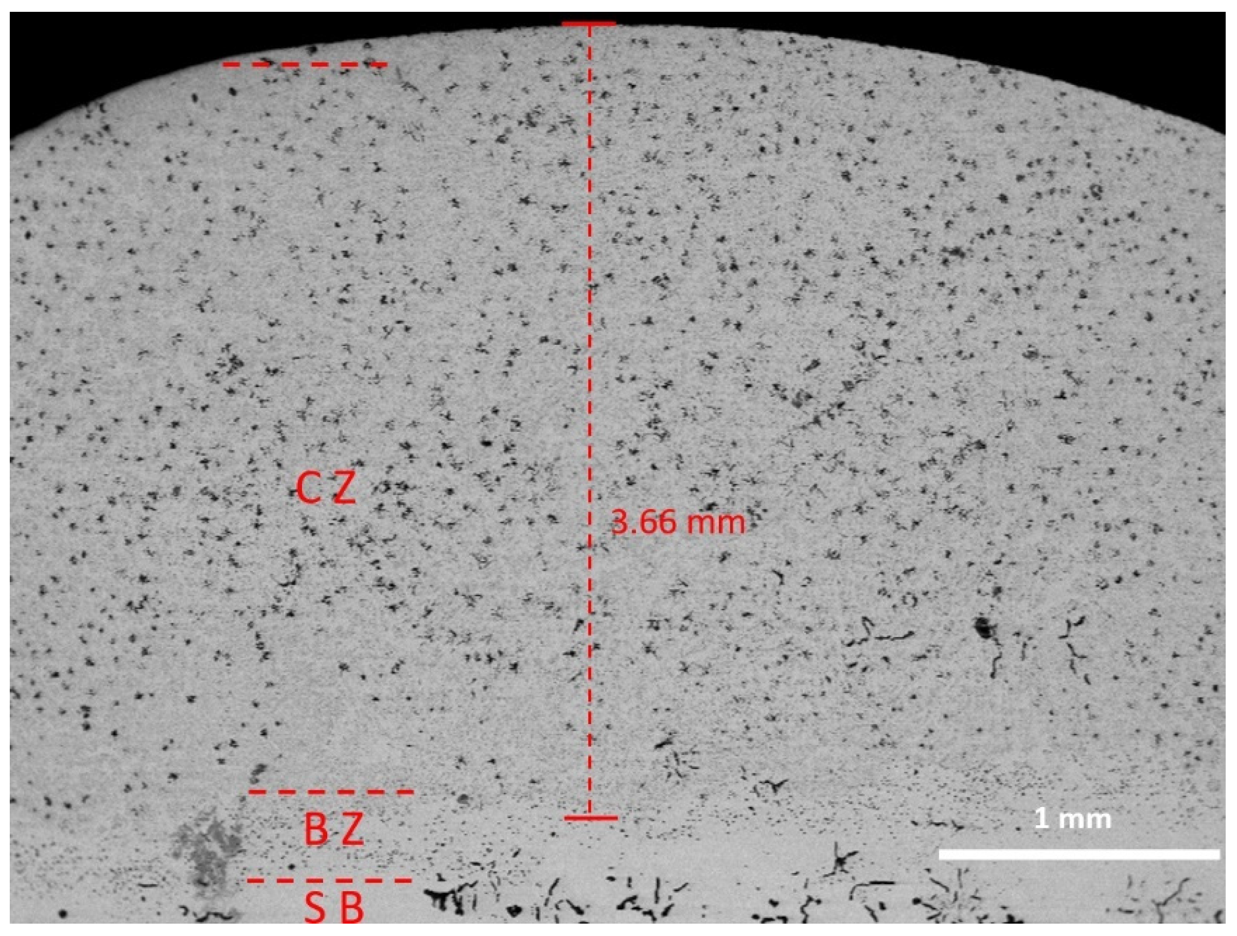
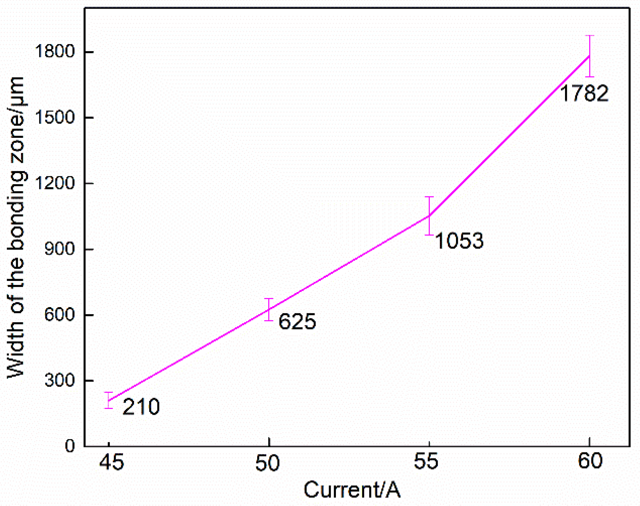
3.1. Mirostructure of the Bonding Zone

Figure 4 shows the global cross-sectional microstructure of the iron-based alloy coating prepared with a 50 A plasma arc current. The separate coating zone (CZ), bonding zone (BZ) and substrate (SB) can be clearly seen. The total coating thickness reached about 3.66 mm.
Figure 5 shows the microstructure of the bonding zone between the iron-based alloy coating and the CGI substrate. Good metallurgical bonding occurred between the iron-based alloy coating and the CGI substrate. A transition zone with a little flake graphite appeared when a single-pass cladded iron-based coating was formed on the grey cast iron, as reported in previous work [33]. In the single-pass cladding, the carbon atoms hardly diffused to form graphite under the huge cooling rate, whereas, in the multiple claddings process, the heat capacity of the deposited cladding was large and the cooling rate decreased, which would be helpful to precipitate carbon in the transition zone. Therefore, a spheroidal graphite transition zone formed between the coating and the substrate as shown in Figure 5a–d. Meanwhile, with the increase of plasma arc current, the quantity of graphite in the binding zone increased continuously. Figure 5a shows the morphology of graphite in the coating bonding zone when the plasma arc current was 45 A. Dendrites with small flakes of graphite formed in the coating zone and a small amount of nodular graphite precipitated in the bonding zone with a bonding coat width of about 210 μm. Figure 6 shows the width of the bonding zone. When the plasma arc current was varied from 55 to 60 to 65 A, the width of the transition zone with spheroidal graphite precipitated varied from 625, 1053 to 1782 μm, respectively. Furthermore, the precipitated graphite became finer and finer with the increase of the plasma arc current, which was the main reasoned for the relatively high cooling rate accompanying the increase of plasma arc currents during the multiple cladding formation. The precipitated graphite morphologies were obviously different in the coating zone, bonding zone and CGI substrate, and corresponded to dendrite flake graphite, spherical graphite and vermicular graphite, respectively. Moreover, the spherical graphite in the bonding zone could reduce the crack sensitivity as compared with the flake graphite, which was helpful to ensure good bonding between the iron-based coating and the CGI substrate.

3.2. Mirostructure of the Coating Zone

Figure 7 shows the cross-sectional microstructure of the iron-based alloy coating prepared under a 50 A plasma arc current. Austenite dendrites were formed in the coating zone. With the increase of the distance from the bottom side of the molten pool to the top surface, the temperature gradient (G) decreased and the solidification rate (R) increased gradually at the same time, which would lead to the ratio of temperature gradient to the solidification rate (G/R) decreasing gradually [8]. Consequently, the dendrites would grow preferentially. Figure 7b shows a magnification of position A. Secondary carbides precipitated from a supersaturated austenite grain. Figure 7c shows the selected positions for element analysis in the magnification of zone B. The detailed elements analysis results are listed in Table 4. The carbon content at position 1 was higher than that at position 2 due to the fact the carbon contents in carbide were much higher than the maximum solubility of carbon in solid solution during cooling. At point 3, the main element was carbon besides Fe, Al and Si. Therefore, point 3 was identified as graphite. In the matrix phase of γ-Fe, aluminum was solidly dissolved into the matrix phase and played a part in solution strengthening [34]. On the whole, the graphite existed in clusters as seen in Figure 7a, while it precipitated intermittently along the austenite grains as shown in Figure 7b.
In comparison, there were spherical graphite particles precipitated in the bonding zone as shown in Figure 7d. Besides spherical graphite, there was a lot of strip cementite perpendicular to the CGI substrate and along the temperature gradient directions as seen in Figure 7d–f. The multiple cladding processing reheated the deposited layer and accelerated the partial decomposition of cementite, which would lead to the decarburization of cementite and form free carbon in the form of spherical graphite.

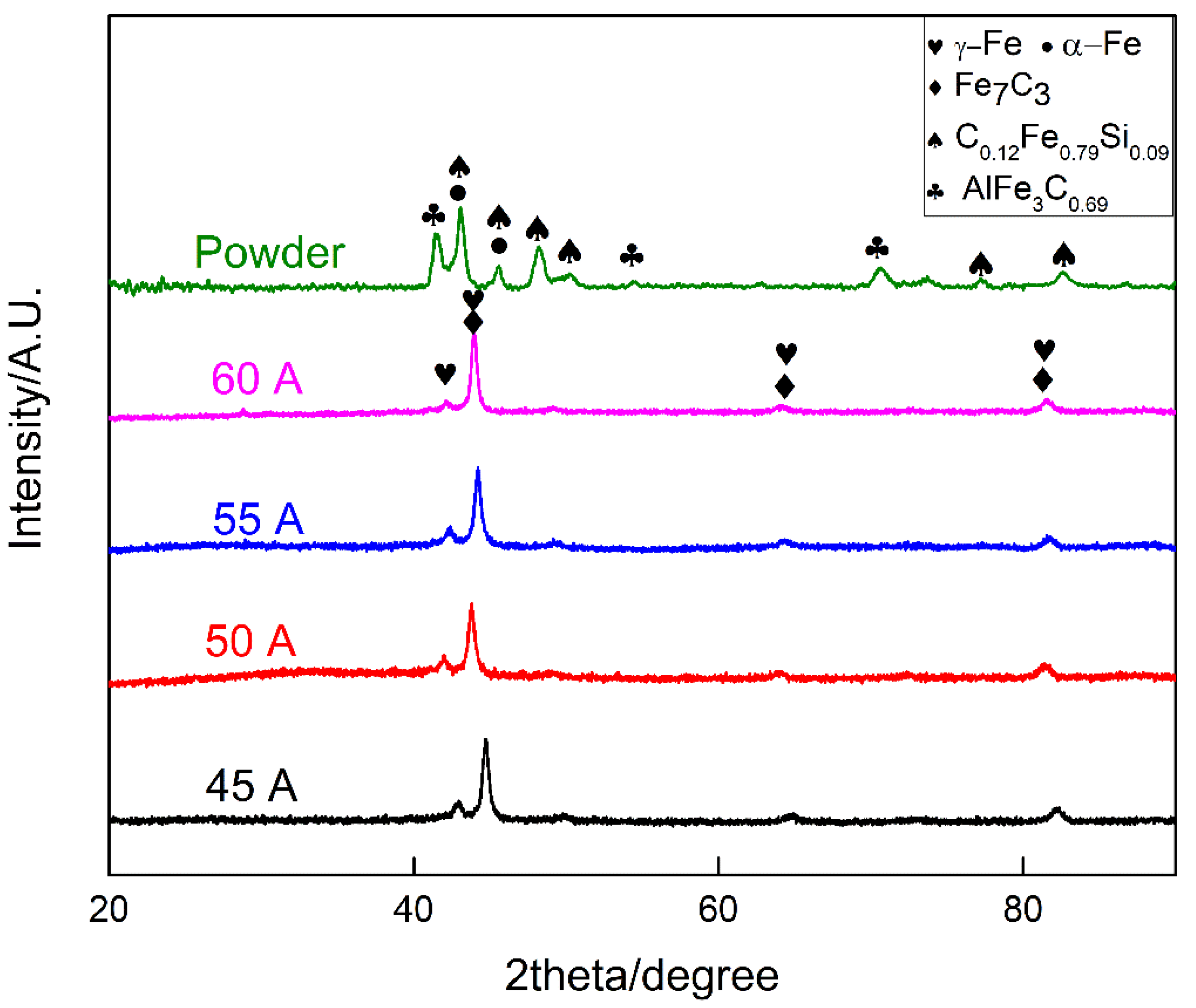
3.3. Phase Composition
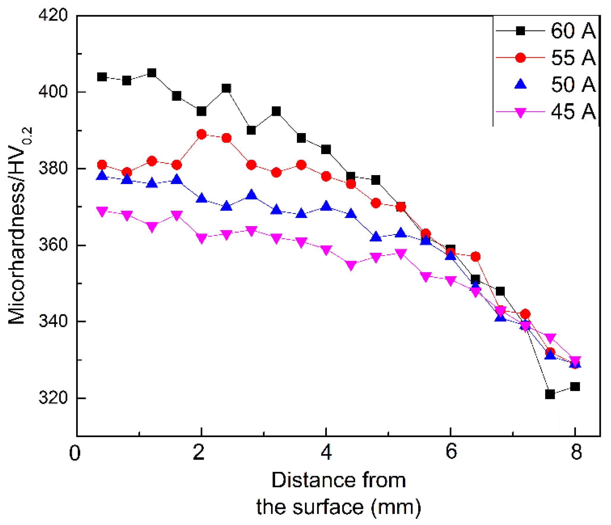
Figure 8 shows the X-ray diffraction patterns of the powder and the coatings prepared at different plasma arc currents. The main phases in the powder were α-Fe solid solution and ternary compounds, including C0.12Fe0.79Si0.09 and AlFe3C0.69. Austenite and Fe7C3 carbide were the main phases of the four coatings. During the plasma cladding, the powder materials experienced rapid-melting and rapid-cooling process. With the increase of the plasma arc current, the overheating extent of the powder materials increased and the cooling time of the melting was prolonged which was beneficial for carbon diffusion and decarburization of cementite as well as the retaining of dendrite austinite. In addition, aluminum was used as alloying element for two purposes. One was to reduce the iron-based alloy’s density. The other was to enabled precipitation hardening effect by the decomposition of the supersaturated austenite to form strengthening phase or take the effects of solid strengthening [35,36], while, in the coatings, no aluminum compounds appeared like the ternary compound AlFe3C0.69 phase in the powder. Generally, the addition of aluminum directly substituted the heavier iron atoms as well as caused a dilation of the lattice [34]. Consequently, the aluminum element in the iron-based alloy played a role of solution strengthening mainly, which would improve the wear properties of the coating.

3.4. Microhardness

Figure 9 shows the coatings’ microhardnesses. The coatings’ microhardnesses presented a gradient distribution and increased from the bonding zone to the cladding layer’s upper surface. The mean microhardnesses of the iron-based coatings were 363, 378, 388, 402 HV when the plasma arc currents were 45, 50, 55 and 60 A, which were higher than that of the CGI substrate. The iron-based alloy coatings’ hardness increased with the increase of the plasma arc currents. The high hardness of the iron-based coating came from the precipitated secondary carbides formed in the coatings. Deng et al. deposited Fe-Mo alloy coating with the mean microhardness of 750 HV, which was mainly due to the rapid cooling of the fine grain microstructure and the formation of a hard intermetallic layer [20]. The molybdenum solid solution in α-Fe phase also contributed to the high microhardness. In addition, Cheng et al. reported the Fe–Cr–C iron-based coating’s microhardness enhancement was also due to the refined microstructure and strong super-saturation solution hardening of Cr to the iron matrix and the hard Cr7C3 phase [13]. Therefore, the change of microstructure led to the increase of coating hardness, which could be helpful to enhance the coating’s wear resistance.

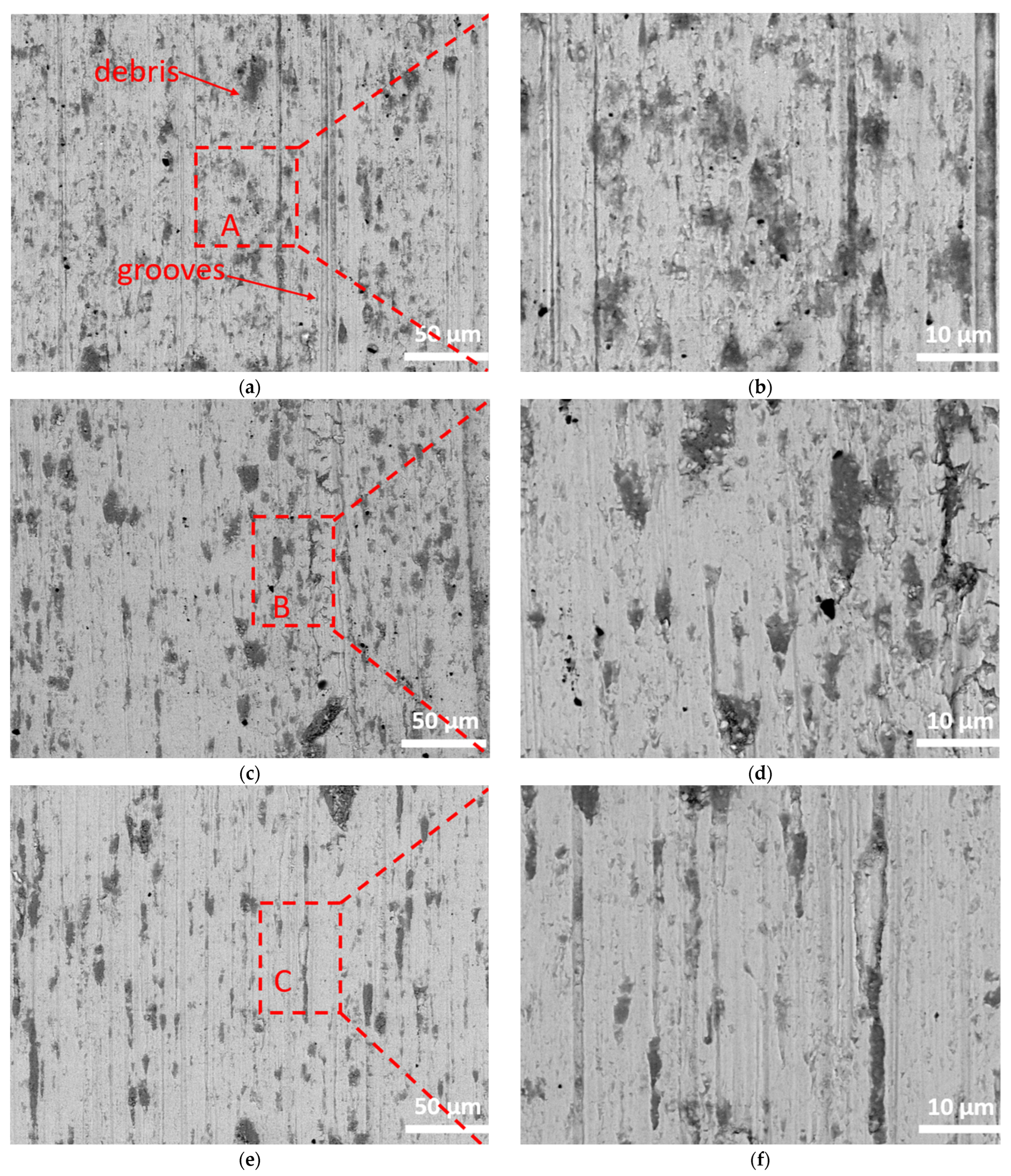
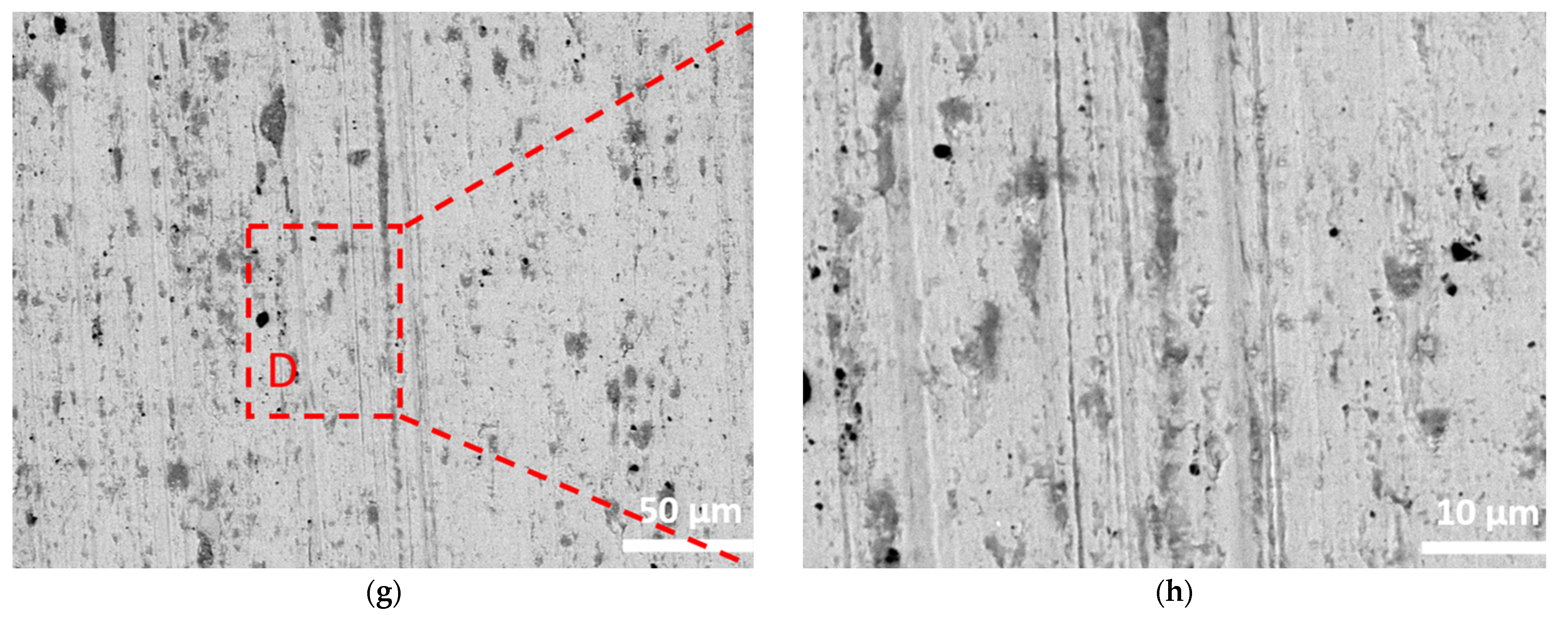
3.5. Wear Properties

Figure 10 shows the frictional coefficients of the iron-based alloy coatings and the CGI substrate. The frictional coefficient vibration, as a function of the testing time and the abrasive process, could be divided into three segments including primary abrasion, normal abrasion and rapid abrasion [37]. The frictional coefficient results indicated that only primary abrasion and normal abrasion happened during the testing. The coatings’ frictional coefficients were approximately in the range of 0.51–0.46 while the CGI substrate’s frictional coefficient was 0.55.
Table 5 shows the statistic frictional coefficients of the iron-based coatings and the CGI substrate. The iron-based coatings exhibited lower friction coefficients than the CGI substrate. With the increase of the plasma arc current, the frictional coefficient of coating did not change linearly, while, due to the graphite solid lubricants, the coatings’ friction coefficients were not very different, and a little lower than that of the CGI substrate.
Figure 11 shows the wear mass losses of the coatings, the CGI substrate and corresponding counterparts after the wear tests. The coating’s wear mass loss decreased with the increase of the plasma arc current. The iron-based coating prepared at a plasma arc current of 60 A exhibited the lowest mass loss of 4.2 mg in the four coatings. As compared to the mass loss of the CGI substrate with the value of 8.2 mg, the coatings’ wear mass losses were significantly reduced, which reflected that the coatings’ wear resistances were higher than that of the CGI substrate. The main reason for the good wear resistance of the iron-based alloy coatings prepared by plasma transfer arc cladding was that the carbide precipitated in the coating acted as the wear-resisting skeleton to enhance the coating’s wear resistance and the precipitated graphite acted as a solid lubricant to lower the frictional coefficient, simultaneously. The GCr15′s hardness was about 60–62 HRC, which was approximately equal to 700–760 HV, while the microhardness of the CGI substrate was in the range of 280~300 HV. GCr15 was thus much harder than the CGI substrate. As for the GCr15 counterpart, GCr15′s martensite and carbides mainly cut into CGI substrate during wear test. With the increase of the coating’s microhardness, the coating’s mass loss was reduced. The wear mass losses of the counterpart to the iron-based alloy coatings were higher than that of the CGI substrate. The iron-based coating prepared at 60 A plasma arc current had the highest microhardness of about 402 HV, which was much higher than that of the CGI substrate and could be attributed to the precipitated secondary carbides formed in the coatings. The wear mass loss of the counterpart to the iron-based coating prepared at 60 A plasma arc current was 2.0 mg, which was a little higher than that of the CGI substrate (1.4 mg), which was mainly attributed to the relatively smaller microhardness difference between the iron-based coating prepared at 60 A plasma arc current and the GCr15 pin than that between the CGI substrate and GCr15. Therefore, combined with both the wear mass loss and frictional coefficient, the iron-based coating prepared at 60 A plasma arc current was preferred for its optimized wear resistance with simultaneous low frictional coefficient and wear mass loss.
Figure 12 shows the worn surface morphologies of the CGI substrate. There were deep plowing grooves in the CGI’s worn surface as seen in Figure 12b, a magnification of position A. Accompanying the wear processing, the worn debris became embedded into the CGI surface and acted as a fixed indenter, which would form cutting, plowing and grooving on the CGI surface with the so-called grooving wear mode as the main abrasive wear mechanism. Therefore, abrasive wear was the main wear form between the compacted graphite cast iron and GCr15 counterpart.
The worn surface morphologies of the iron-based alloy coatings prepared at 45, 50, 55 and 60 A plasma arc currents are shown in Figure 13, where it can be seen that there were no spalling and adhesion characteristics on the iron-based coatings’ worn surface. The main worn characters on the iron-based coatings’ worn surface of were micro cutting furrow and plowings. The plowing grooves on the worn surfaces of the coatings prepared at 45 A plasma arc current was more serious as compared with other coatings. Figure 13b shows the magnification of position A. There were amounts of wear debris on the worn surface of the iron-based coating prepared at 45 A plasma arc current, which was due to the great plastic deformation as well as surface peeling of the coating caused by the hard GCr15 counterpart in the friction process. Meanwhile, the wear debris would induce severe three-body abrasive wear in the sliding processing, which would aggravate the wear process and produce more grooves on the surface of the iron-based coating prepared at 45 A current. Figure 13d–g show the worn surface morphologies of the iron-based coatings prepared at 50 and 55 A plasma arc currents. There were lower grooves and less wear debris as compared to that of the coating prepared at 45 A, which caused the decrease of the wear mass loss. This phenomenon was related to the improved coating hardness with the increase of plasma arc current. When the plasma current increased to 60 A, the iron-based coating had the highest hardness and the precipitated secondary carbides formed in the coatings would be helpful for its wear resistance. As shown in Figure 13g,h, the plowing grooves and wear debris were less than that of the coating prepared at 45, 50 and 55 A plasma arc currents. Meanwhile, it had the lowest wear mass loss 4.2 mg, which exhibited the best wear resistance in the four iron-based coatings. Therefore, the coating’s wear mechanism was abrasive wear, which was similar to the CGI’s wear mechanism.
Figure 14 shows the iron-based coatings’ wear schematic. The coating’s wear resistance was closely related to the microstructure and main phases. The secondary carbides precipitated from a supersaturated austenite grain and formed a wear-resisting skeleton in the coating. Moreover, aluminum played a solid solution strengthening effect during the cladding. Due to the high hardness of carbide and aluminum solid strengthening effect, the coating had exceptional abrasive wear resistance. Moreover, the precipitated graphite had a self-lubricating effect that reduced the friction coefficient. Both the high hardness and self-lubrication contributed simultaneously to the high wear resistance of the iron-based coatings.

4. Conclusions

Multiple cladded thick claddings were prepared on a compacted graphite cast iron (CGI) substrate with iron-based powders through plasma transfer arc cladding using different plasma arc currents to improve the CGI’s wear resistance. The iron-based coating’s minimum frictional coefficient and wear mass loss were about 0.48 and 4.2 mg, respectively when the current was 60 A, which were lower than the values of a compacted graphite iron substrate with a frictional coefficient and wear mass loss of 0.55 and 8.2 mg. Compared with the substrate, the iron-based alloy cladding layer achieved the effect of reducing friction and wear resistance simultaneously, which resulted from the self-lubricating effect of graphite and high wear-resistance of carbides in the claddings. The iron-based coatings had a similar abrasive wear mechanism to the CGI, and could be used to repair or remanufacture CGI workpieces.

Author Contributions

Conceptualization, P.G., B.C. and M.L.; methodology, P.G., B.C., B.Z., D.Z. (Daming Zhao), W.W. and M.L.; software, P.G., B.C., Y.G. and C.J.; validation, P.G., B.C. and B.Z.; formal analysis, P.G., B.C and Z.Y.; investigation P.G., B.C., B.Z., D.Z. (Daming Zhao), W.W., Y.L., L.J. and D.Z. (Dan Zhao); data curation, Z.Y.; writing—original draft preparation, B.C.; writing—review and editing, P.G.; project administration, J.L.; funding acquisition, P.G. and J.L. All authors have read and agreed to the published version of the manuscript.

Funding

This work was funded by the National Natural Science Foundation of China (51771140), Key Project of Equipment Pre-search Field Fund (6140922010301), Shaanxi Key Science and Technology Innovation Team (2017KCT-05), The Youth Innovation Team of Shaanxi Universities: Metal Corrosion Protection and Surface Engineering Technology, Shaanxi Provincial Key Research and Development Project (2019ZDLGY05-09), Local Serving Special Scientific Research Projects of Shaanxi Provincial Department of Education (19JC022), Project of Yulin Science and Technology Bureau (2019-121).

Institutional Review Board Statement

Not applicable.

Informed Consent Statement

Not applicable.

Data Availability Statement

Not applicable.

Conflicts of Interest

The authors declare no conflict of interest.

References

  1. Popov, P.I.; Sizov, I.G. Effect of alloying elements on the structure and properties of iron with vermicular graphite. Met. Sci. Heat Treat. 2006, 48, 272–275. [Google Scholar] [CrossRef]
  2. Keller, J.; Fridrici, V.; Kapsa, P.; Vidaller, S.; Huard, J.F. Influence of chemical composition and microstructure of gray cast iron on wear of heavy duty diesel engines cylinder liners. Wear 2007, 263, 1158–1164. [Google Scholar] [CrossRef]
  3. Lin, Y.; He, S.; Lai, D.; Wei, J.; Ji, Q.; Huang, J.; Pan, M. Wear Mechanism and Tool Life Prediction of High-Strength Vermicular Graphite Cast Iron Tools for High-Efficiency Cutting. Wear 2020, 454–455, 203319. [Google Scholar] [CrossRef]
  4. Sawant, M.S.; Jain, N.K. Investigations on Wear Characteristics of Stellite Coating by Micro-Plasma Transferred Arc Powder Deposition Process. Wear 2017, 378–379, 155–164. [Google Scholar] [CrossRef]
  5. Li, G.; Gan, Y.; Liu, C.; Shi, Y.; Zhao, Y.; Kou, S. Corrosion and Wear Resistance of Fe-Based Amorphous Coatings. Coatings 2020, 10, 73. [Google Scholar] [CrossRef] [Green Version]
  6. Jamari, J.; Ammarullah, M.I.; Saad, A.P.M.; Syahrom, A.; Uddin, M.; van der Heide, E.; Basri, H. The Effect of Bottom Profile Dimples on the Femoral Head on Wear in Metal-on-Metal Total Hip Arthroplasty. J. Funct. Biomater. 2021, 12, 38. [Google Scholar] [CrossRef]
  7. Gao, P.H.; Chen, B.Y.; Zeng, S.C.; Yang, Z.; Guo, Y.C.; Liang, M.X.; Xu, T.; Li, J.P. Effect of Vacuum Annealing on the Nickel-Based Coatings Deposited on a CGI Cast Iron through Atmospheric Plasma Spraying. Metals 2020, 10, 963. [Google Scholar] [CrossRef]
  8. Zhou, Y.; Zhang, J.; Xing, Z.; Wang, H.; Lv, Z. Microstructure and Properties of NiCrBSi Coating by Plasma Cladding on Gray Cast Iron. Surf. Coat. Technol. 2019, 361, 270–279. [Google Scholar] [CrossRef]
  9. Li, Y.; Dong, S.; Yan, S.; Liu, X.; He, P.; Xu, B. Microstructure Evolution during Laser Cladding Fe-Cr Alloy Coatings on Ductile Cast Iron. Opt. Laser Technol. 2018, 108, 255–264. [Google Scholar] [CrossRef]
  10. Gao, P.H.; Fu, R.T.; Chen, B.Y.; Zeng, S.C.; Zhang, B.; Yang, Z.; Guo, Y.C.; Liang, M.X.; Li, J.P.; Lu, Y.Q.; et al. Corrosion Resistance of CoCrFeNiMn High Entropy Alloy Coating Prepared through Plasma Transfer Arc Claddings. Metals 2021, 11, 1876. [Google Scholar] [CrossRef]
  11. Xie, G.Z.; Song, X.L.; Zhang, D.J.; Wang, Y.P.; Li, P.H. Microstructure and Corrosion Properties of Thick WC Composite Coating Formed by Plasma Cladding. Appl. Surf. Sci. 2010, 256, 6354–6358. [Google Scholar]
  12. Zhang, L.M.; Sun, D.B.; Yu, H.Y.; Li, Y.Q. Characteristics of Fe-based alloy coating produced by plasma cladding process. Mater. Sci. Eng. A 2007, 457, 319–324. [Google Scholar] [CrossRef]
  13. Cheng, J.B.; Xu, B.S.; Liang, X.B.; Wu, Y.X. Microstructure and Mechanical Characteristics of Iron-Based Coating Prepared by Plasma Transferred Arc Cladding Process. Mater. Sci. Eng. A 2008, 492, 407–412. [Google Scholar] [CrossRef]
  14. Gao, P.H.; Chen, B.Y.; Wang, W.; Jia, H.; Li, J.P.; Yang, Z.; Guo, Y.C. Simultaneous increase of friction coefficient and wear resistance through HVOF sprayed WC-(nano WC-Co). Surf. Coat. Technol. 2019, 363, 379–389. [Google Scholar] [CrossRef]
  15. Wang, H.; Qiu, Q.; Gee, M.; Hou, C.; Liu, X.; Song, X. Wear Resistance Enhancement of HVOF-Sprayed WC-Co Coating by Complete Densification of Starting Powder. Mater. Des. 2020, 191, 108586. [Google Scholar] [CrossRef]
  16. Gao, P.H.; Li, J.P.; Yang, Z.; Guo, Y.C.; Wang, Y.R. Preparation of Al/SiC Composite Coatings on Surface of Aluminum Alloy by Atmospheric Plasma Spraying. Rare Metal. Mater. Eng. 2015, 44, 2396–2400. [Google Scholar]
  17. Liu, Y.; Zhan, X.; Yi, P.; Liu, T.; Liu, B.; Wu, Q. Research on the Transformation Mechanism of Graphite Phase and Microstructure in the Heated Region of Gray Cast Iron by Laser Cladding. Opt. Laser Technol. 2018, 100, 79–86. [Google Scholar] [CrossRef]
  18. Ma, Q.; Dong, Z.; Ren, N.; Hong, S.; Chen, J.; Hu, L.; Meng, W. Microstructure and Mechanical Properties of Multiple In-Situ-Phases-Reinforced Nickel Composite Coatings Deposited by Wide-Band Laser. Coatings 2021, 11, 36. [Google Scholar] [CrossRef]
  19. Lv, J.; Zhang, C.; Chen, Z.; Bai, D.; Zhang, Y.; Li, G.; Lu, X. Fabrication and Characterization of Ni60A Alloy Coating on Copper Pipe by Plasma Cladding with Induction Heating. Coatings 2021, 11, 1080. [Google Scholar] [CrossRef]
  20. Deng, X.; Zhang, G.; Wang, T.; Ren, S.; Bai, Z.; Cao, Q. Investigations on Microstructure and Wear Resistance of Fe-Mo Alloy Coating Fabricated by Plasma Transferred Arc Cladding. Surf. Coat. Technol. 2018, 350, 480–487. [Google Scholar] [CrossRef]
  21. Zhao, H.; Li, J.J.; Zheng, Z.Z.; Wang, A.H.; Huang, Q.H.; Zeng, D.W. Microstructure and high-temperature wear properties of in situ TiC composite coatings by plasma transferred arc surface alloying on gray cast iron. Int. J. Miner. Met. Mater. 2015, 22, 1273. [Google Scholar] [CrossRef]
  22. Lyu, Y.; Sun, Y.; Jing, F. On the Microstructure and Wear Resistance of Fe-Based Composite Coatings Processed by Plasma Cladding with B4C Injection. Ceram. Int. 2015, 41, 10934–10939. [Google Scholar] [CrossRef]
  23. Zhou, S.F.; Xu, Y.B.; Liao, B.Q.; Sun, Y.J.; Dai, X.Q.; Yang, J.X.; Li, Z.Y. Effect of laser remelting on microstructure and properties of WC reinforced Fe-based amorphous composite coatings by laser cladding. Opt. Laser Technol. 2018, 103, 8–16. [Google Scholar] [CrossRef] [Green Version]
  24. Fan, L.; Dong, Y.H.; Chen, H.Y.; Dong, L.H.; Yin, Y.S. Wear Properties of Plasma Transferred Arc Fe-Based Coatings Reinforced by Spherical WC Particles. J. Wuhan Univ. Technol.—Mater. Sci. Ed. 2019, 34, 433–439. [Google Scholar] [CrossRef]
  25. Nie, G.M.; Huang, C.; Li, B.; Zhong, J.; Wang, S. Fabrication and application status of Fe-based amorphous alloy coatings. Surf. Coat. Technol. 2017, 46, 18–26. [Google Scholar]
  26. Koga, G.; Schulz, R.; Savoie, S.; Nascimento, A.; Drolet, Y.; Bolfarini, C.; Kiminami, C.; Botta, W. Microstructure and wear behavior of Fe-based amorphous HVOF coatings produced from commercial precursors. Surf. Coat. Technol. 2017, 309, 938–944. [Google Scholar] [CrossRef]
  27. Zhang, C.; Zhang, Z.-W.; Chen, Q.; Liu, L. Effect of hydrostatic pressure on the corrosion behavior of HVOF-sprayed Fe-based amorphous coating. J. Alloys Compd. 2018, 758, 108–115. [Google Scholar] [CrossRef]
  28. Cao, S.; Liang, J.; Zhou, J.; Wang, L. Microstructure Evolution and Wear Resistance of In-Situ Nanoparticles Reinforcing Fe-Based Amorphous Composite Coatings. Surf. Interfaces 2020, 21, 100652. [Google Scholar] [CrossRef]
  29. Sun, B.; Cheng, J.; Cai, Z.; Zhao, H.; Zhang, Z.; Qu, H.; Zhang, Q.; Hong, S.; Liang, X. Formation and Wear Property of Broad-Beam Laser Clad Fe-Based Coatings. Surf. Coat. Technol. 2021, 405, 126598. [Google Scholar] [CrossRef]
  30. Xiao, M.; Gao, H.; Sun, L.; Wang, Z.; Jiang, G.; Zhao, Q.; Guo, C.; Li, L.; Jiang, F. Microstructure and Mechanical Properties of Fe-Based Amorphous Alloy Coatings Prepared by Ultra-High Speed Laser Cladding. Mater. Lett. 2021, 297, 130002. [Google Scholar] [CrossRef]
  31. Li, K.; Liang, J.; Zhou, J. Preparation and Characterization of Laser Cladded FeCrMoBSi Amorphous Composite Coatings. Surf. Coat. Technol. 2021, 423, 127520. [Google Scholar] [CrossRef]
  32. Lu, Y.; Huang, G.; Wang, Y.; Li, H.; Qin, Z.; Lu, X. Crack-free Fe-based amorphous coating synthesized by laser cladding. Mater. Lett. 2017, 210, 46–50. [Google Scholar] [CrossRef]
  33. Gao, P.H.; Chen, B.Y.; Zhang, B.; Yang, Z.; Guo, Y.C.; Li, J.P.; Liang, M.X.; Li, Q.P. Preparations of iron-based alloy coatings on grey cast iron through plasma transfer arc welding. J. Adhes. Sci. Technol. 2021. [Google Scholar] [CrossRef]
  34. Ley, N.A.; Young, M.L.; Hornbuckle, B.C.; Field, D.M.; Limmer, K.R. Toughness Enhancing Mechanisms in Age Hardened Fe–Mn–Al–C Steels. Mater. Sci. Eng. A. 2021, 820, 141518. [Google Scholar] [CrossRef]
  35. Kim, H.; Suh, D.-W.; Kim, N.J. Fe-Al-Mn-C lightweight structural alloys: A review on the microstructures and mechanical properties. Sci. Technol. Adv. Mater. 2013, 14, 1–14. [Google Scholar] [CrossRef] [PubMed]
  36. Frommeyer, G.; Brüx, U. Microstructures and mechanical properties of high-strength Fe-Mn-Al-C light-weight TRIPLEX steels. Steel Res. Int. 2006, 77, 627–633. [Google Scholar] [CrossRef]
  37. Zhang, L. Preparation and Properties of the Ni-Al/Fe-Al Intermetallics Composite Coating Produced by Plasma Cladding. Int. J. Miner. Met. Mater. 2011, 6, 725. [Google Scholar] [CrossRef]
Figure 1. Iron-based powder: (a) global morphology, (b) cross-sectional microstructure.
Coatings 12 00243 g001
Figure 2. Microstructure of the compacted graphite cast iron.
Coatings 12 00243 g002
Figure 3. PTA cladding system schematic and sample preparation.
Coatings 12 00243 g003
Figure 4. Cross-sectional micro-structure of the iron-based alloy coating prepared with a 50 A plasma arc current.
Coatings 12 00243 g004
Figure 5. Microstructure of the bonding zone: (a) 45 A, (b) 50 A, (c) 55 A, (d) 60 A.
Coatings 12 00243 g005
Figure 6. Width of the bonding zone.
Coatings 12 00243 g006
Figure 7. Microstructure of the coatings prepared at 50 A: (a) coating zone, (b) magnification of position A, (c) magnification of position B, (d) bonding zone, (e) magnification of position C, (f) magnification of position D.
Coatings 12 00243 g007aCoatings 12 00243 g007b
Figure 8. X-ray diffraction plots of the powder and coatings.
Coatings 12 00243 g008
Figure 9. Microhardness of the iron-based alloy coatings.
Coatings 12 00243 g009
Figure 10. Frictional coefficient of the iron-based coatings and the CGI substrate.
Coatings 12 00243 g010
Figure 11. Wear mass loss of the coatings, CGI substrate and the corresponding counterparts.
Coatings 12 00243 g011
Figure 12. Worn surface morphologies (a) CGI substrate, (b) magnification of position A.
Coatings 12 00243 g012
Figure 13. Worn surface morphologies of the iron-based coatings (a) 45 A, (b) magnification of position A (c) 50 A, (d) magnification of position B, (e) 55 A, (f) magnification of position C, (g) 60 A, (h) magnification of position D.
Coatings 12 00243 g013aCoatings 12 00243 g013b
Figure 14. Wear schematic of the iron-based coatings.
Coatings 12 00243 g014
Table 1. Chemical composition of the iron-based powders.
ElementCAlSiMnFe
Wt.%5.763.873.341.17Bal.
Table 2. Chemical composition of the CGI substrate.
ElementCSiMnPSFe
Wt.%3.5–3.82.0–2.3≤0.6≤0.09≤0.006Bal.
Table 3. Plasma cladding parameters.
Plasma Arc Current
A
Plasma
Gas Flow
L/min
Protective
Gas Flow
L/min
Powder
Feeding Rate
rad/min
Scanning Velocity
mm/min
Distance from the Torch Exit to the Substrate
mm
451.5101518010
501.5101518010
551.5101518010
601.5101518010
Table 4. Point analysis of elements in the selected areas.
Element (wt.%)CAlSiMnFe
110.721.062.372.0783.78
24.822.913.211.0887.98
365.980.871.28-31.86
413.45---86.55
56.44-2.17-91.39
Table 5. Statistic frictional coefficients of the iron-based coatings and the CGI substrate.
Type45 A50 A55 A60 ASubstrate
Friction coefficient0.46 ± 0.020.47 ± 0.030.51 ± 0.020.48 ± 0.030.55 ± 0.05
Publisher’s Note: MDPI stays neutral with regard to jurisdictional claims in published maps and institutional affiliations.

