Article

Long-Term Durability of Robust Super-Hydrophobic Co–Ni-Based Coatings Produced by Electrochemical Deposition

1
National Center for Materials Service Safety, University of Science and Technology Beijing, Beijing 100083, China
2
School of Physics Science and Engineering, Institute for Advanced Study, Tongji University, Shanghai 200092, China
3
Department of Engineering Mechanics, Tsinghua University, Beijing 100084, China
*
Authors to whom correspondence should be addressed.
These authors contributed equally to this work.
Coatings 2022, 12(2), 222; https://doi.org/10.3390/coatings12020222
Submission received: 31 December 2021 / Revised: 28 January 2022 / Accepted: 31 January 2022 / Published: 9 February 2022
(This article belongs to the Special Issue Superhydrophobic and Superoleophobic Surfaces)

Abstract

:
The long-term durability for two kinds of Co–Ni-based robust coatings, the Co–Ni super-hydrophobic (Co–Ni SHPB) coating and Co–Ni/WC super-hydrophobic (Co–Ni/WC SHPB) coating, was analyzed through an immersion test in 3.5 wt.% NaCl solution. The evolution of their surface properties was characterized by scanning electron microscope (SEM) images, energy-dispersive spectrometry (EDS), a wettability measurement and X-ray photoelectron spectrometer (XPS), and the evolution of anti-corrosion mechanisms was evaluated with electrochemical measurements. The results show that as-prepared two kinds of robust coatings display a good long-term durability, with the Co–Ni SHPB coating and Co–Ni/WC SHPB coating losing their super-hydrophobicity after being immersed for more than 10 days. Additionally, both kinds of coatings present efficient corrosion protection even after long-term immersion.

1. Introduction

Super-hydrophobic coatings inspired by biological species have been an important research field due to the huge application potential in the field of corrosion inhibition [1,2], anti-icing areas [3,4], oil/water separation [5,6] and drag reduction research [7]. Generally, the super-hydrophobicity on a solid surface created by a hierarchical rough surface and hydrophobic groups is defined as a static water contact angle (WCA) of no less than 150° and a water sliding angle (WSA) of no more than 10°. Currently, creating micro–nano structures and modifying rough surfaces using low-surface energy substances has been the main approach to prepare super-hydrophobic surfaces [8]. So far, many ways have been developed to prepare super-hydrophobic surfaces, such as chemical/electrochemical etching [9], femtosecond laser etching [10,11], physical/chemical vapor deposition [12], electrochemical deposition [13,14], anodic oxidation [3] and colloidal coating [15]. Among them, the electrochemical deposition technique was considered as a method with a simple operation, low cost and large area [16,17]. However, due to the fragile micro–nano structures and desorption of hydrophobic groups on the surface, the large-scale industrial promotion of artificial super-hydrophobic surfaces was usually restricted by mechanical durability and chemical stability [18,19]. For most super-hydrophobic surfaces that have been reported in the literature, it was easy for them to lose their super-hydrophobicity after conventional liner abrasion tests [19] or finger touch tests [20]. In order to solve this issue, many researchers from various countries have undertaken many efforts, including changing the surface micro–nano structure morphology [21] and adding second-phase particles [22,23]. Furthermore, PEO coatings exhibit excellent wear resistance in tribo-electrochemical tests and are potential materials for the preparation of wear-resistant superhydrophobic coatings [24]. In order to obtain super-hydrophobicity and an improved abrasion resistance, the surface structures are of vital importance. In the abrasion test, the hierarchically structured micro–nano surface exhibits better wear resistance, where the protruding microstructure protects the nanostructure from damage and maintains super-hydrophobicity [21].
In addition, the super-hydrophobic coatings are expected to be needed for long-term use in various corrosive media, and so chemical stability has been considered to be an important factor in practical applications. Yu et al. developed the super-hydrophobic P25/attapulgite (ATP)/epoxy resin (ER)/polydimethylsiloxane coating (PDMS), which could withstand 30 days of outdoor environment exposure and 24 h UV durability tests, exhibiting the long-term stability and UV durability [25]. Su et al. prepared an Ni-based super-hydrophobic coating on a bare Cu substrate through electrochemical deposition, which showed a good stability under both acidic and alkaline corrosive media. Moreover, the coating remained super-hydrophobic after immersion in water for 6 days [26].
At present, research on the long-term durability of super-hydrophobic coatings is limited and there are fewer studies on their failure process. Vanithakumari et al. fabricated a super-hydrophobic Ti coating with a two-step method involving anodization and silane modification. Only the wettability changes were recorded by immersion in flowing water and sea water [27]. Wang et al. prepared a super-hydrophobic surface on a bare zinc substrate using the hydrothermal method, where the stability of corrosion resistance was evaluated by the open circle potential (OCP) curves and electrochemical impedance spectroscopy (EIS) plots after having been immersed in a NaCl solution for 10 days. The OCP value and impedance reduced significantly after 10 days of immersion, suggesting the degradation of the corrosion resistance performance due to the gradual replacement of the air film by corrosive media [28]. However, the evolution of the surface morphology, chemical composition and wettability was not provided.
In previous work, the Co–Ni SHPB coatings with cauliflower-like structures were developed via a one-step electrodeposition and had excellent wear resistance [21]. Moreover, the linear abrasion test showed that they lost their super-hydrophobicity when the friction distance exceeded 12 m under a pressure of 5 kPa. Subsequently, the Co–Ni/WC SHPB coating was obtained by co-electrodeposition and the critical friction distance at which the coating loses super-hydrophobicity under a pressure of 5 kPa exceeded 34 m [29]. In this work, the long-term durability of two kinds of Co–Ni-based robust coatings was evaluated through a series of immersion tests in NaCl solution, and the evolution of the surface morphology, chemical composition, wetting properties and corrosion resistance was investigated systematically.

2. Materials and Methods

Carbon steel (Q235) was cut into 10 mm × 10 mm × 2 mm as the substrate in this work. All chemical products were provided by Beijing Yinuokai Technology Co., Ltd. (Beijing, China), including cobalt chloride (CoCl2·6H2O), boric acid (H3BO3), nickel chloride (NiCl2·6H2O), tungsten carbide (WC) powder and perfluorooctyltrichlorosilane (C8H4Cl3F13Si, PFTEOS). Among them, perfluorooctyltrichlorosilane (C8H4Cl3F13Si, PFTEOS) was used as the low surface energy modification material.
The fabrication of two kinds of super-hydrophobic coatings involved electrodeposition process and modification of rough surfaces with PFTEOS. The electrolyte solution contained CoCl2·6H2O (0.1 mol/L) and NiCl2·6H2O (0.02 mol/L), and WC powder as added particles. The electrodeposition process was performed under a standard three-electrode system, in which a saturated calomel electrode (SCE) was selected as the reference electrode, a platinum sheet was selected as the counter electrode, and the carbon steel substrate was used as the working electrode. At a deposition potential of –1.7 V, the Co–Ni rough surface with micro–nano structures was prepared, and the rough surface of the Co–Ni/WC micro-structure was obtained by adding 0.02 M WC powder to the deposition solution.
The super-hydrophobicity was obtained by modifying the hydrophobic groups in the PFTEOS ethanol solution at room temperature, and the soaking time was 20 min. After modification, samples were naturally air dried for later use. All immersion experiments were carried out in 3.5 wt.% NaCl solution at room temperature.
The surface morphologies of coatings were observed by the scanning electron microscope (SEM, ZEISS Gemini 500, Zeiss, Jena, Germany). The chemical distributions on the surface of the samples were studied with energy-dispersive spectrometry (EDS, Oxford Instruments, Abingdon, UK). The wetting properties were evaluated by automatic Contact Angle Measurement System (Data Physics OCA15EC, Filderstadt, Germany), where the droplets volume of WCA was close to 5 μL and droplets volume of WSA was close to 12 μL, respectively. The X-ray photoelectron spectrometer (XPS, PHI Quantera SXM, ULVAC-PHI, Osaka, Japan) was used to investigate the surface chemistry information of the coatings ulvac-phibefore and after immersion.
The corrosion resistance test, including potentiodynamic curves and electrochemical impedance spectroscopy (EIS), was carried out with an automatic electrochemical system (Gamry, Reference 600, Warminster, PA, USA) in 3.5 wt.% NaCl solution. All tests were performed under a three-electrode cell with the platinum plate as counter electrode, the coatings as working electrodes, and saturated calomel electrode (SCE, INSEA SCIENTIFIC INSTRUMENT Co., Ltd, Shanghai, China) as reference electrode. The potentiodynamic curves were measured with a constant scan rate of 0.5 mV/s from –0.6 to 0 V versus SCE. At the open circuit potential (OCP), the EIS measurements were investigated in the frequency range of 105 to 10−2 Hz under the amplitude signal of 5 mV, and the measurement data were fitted using the software ZSimpWin (Version 3.3, AMETEK Scientific Instruments, Oak Ridge, TN, USA). Corrosion tests were repeated three times on different samples.

3. Results and Discussion

3.1. Surface Wetting Property of Two Super-Hydrophobic Coatings with Immersion Time

Figure 1 displays the wetting properties performance of two super-hydrophobic coatings as a function of immersion time, including changes in the WCAs and WSAs after immersion in corrosive media. For the Co–Ni SHPB coating, the WCAs were slightly decreased from 162 ± 1° to 152 ± 2°, and the WSAs were slightly increased from 1 ± 0.5° to 13 ± 2° as the immersion time in 3.5 wt.% NaCl solution of up to 25 days (Figure 1a). In this case, it could be observed that the loss of super-hydrophobicity (i.e., when the WSA was larger than 10°) occurred for the immersion time of approximately 10 to 25 days. For the Co–Ni/WC SHPB coating, the WCAs were slightly decreased from 161° to 149° and the WSAs were slightly increased from 2° to 15° after immersion for 15 days (Figure 1b). Additionally, the immersion time was approximately 10 to 15 days when the super-hydrophobic property was destroyed. These results suggested that the immersion process in the NaCl solution could greatly affect the wetting properties.

3.2. Surface Morphology of Two Super-Hydrophobic Coatings with Immersion Time

In order to further understand the reasons for the wetting variations of the coatings before and after the immersion process, the evolution of microstructure was investigated, which was shown in Figure 2. The Co–Ni SHPB coating shown in Figure 2a exhibited its cauliflower-like structures. Figure 2b,c shows the morphology variations of the SHPB Co–Ni coating after immersion for 10 days and 25 days, respectively. The cauliflower-like micro–nano structures were gradually being damaged by corrosive ions, and bonded into lumps after immersion for 25 days (Figure 2c). Figure 2d shows the typical morphology of the Co–Ni/WC SHPB composite coating of the layered micro–nano structures. After immersion for 10 days and 15 days, the micro–nano structures experienced more pronounced corrosion. Revealed from the cross-sectional images, the change of coating thickness and adhesion before and after immersion was not obvious, and there was a small amount of corrosion products on the coatings’ surface after immersion.

3.3. Elements Distribution on Coating Surfaces after Immersion Test

To better describe the elements distribution on the coating surface, EDS elemental mappings were conducted on the Co–Ni SHPB coating after immersion for 25 days and the Co–Ni/WC SHPB composite coating after immersion for 15 days, which were shown in Figure 3. Both coatings exhibited a similar elemental composition, including a Co–Ni substrate, amounts of CoO and traces of NiO and FeO. As we know, the existence of the pinholes was inevitable, allowing small molecules of corrosive media to penetrate through and corrode the inner carbon steel. The surface morphology of the corroded Co–Ni SHPB coating (Figure 3a) and the corresponding EDS elemental map (Figure 3c) displayed that the Co–Ni substrate surface was covered with a large amount of corrosion products such as CoO and NiO. For the corroded Co–Ni/WC SHPB coating (Figure 3b,d), more corrosion products were generated and their aggregations were more obvious, which resulted in the loss of detection of the WC particles.
For the immersion process of the Co–Ni SHPB coating, the EDS results indicated that the cobalt content on the coating increased from 78.2% to around 85.1%, and the nickel content decreased from 21.8% to 11.2% after immersion for 25 days (Table 1). The oxygen and iron content increased slightly with the immersion time of 10 days and 25 days. For the Co–Ni/WC SHPB coating (Table 2), the cobalt content decreased from 69.0% to around 41.0%, the nickel content from 21.2% to 8.2% and the WC content from 9.8% to 3.3%, respectively. The oxygen and iron content increased significantly during the immersion process compared to the SHPB Co–Ni coating, where the oxygen content increased to 11.1% and the iron content increased 36.4% after the 15 days immersion time, indicating that more corrosion products were generated and the Co–Ni/WC SHPB coating encountered more damage.

3.4. Surface Composition of Two Super-Hydrophobic Coatings with Immersion Time

To investigate the chemical states evolution of the elements, XPS was conducted before and after the immersion test and calibrated by using 284.4 eV C 1s and 870.13 eV Ni 2p together. The obtained spectra containing peaks of the F and C elements indicated that the hydrophobic groups successfully self-adsorbed on the surface of the coating as depicted in Figure 4. The total XPS survey spectra (Figure 4a) and F 1s high-resolution core level (Figure 4c) illustrated strong signals of F 1s core levels before the immersion test, and the signal strength of F 1s dropped significantly as the immersion time increased to 25 days. To further investigate the evolution of the surface chemical state, Figure 4b shows the XPS high-resolution of the C 1s core level, where the signals of the –C–CF2– group, –C–F2– group and –C–F3 group can be identified according to the peaks at the binding energy of 288.7, 291.1 and 293.6 eV, respectively [26,28]. Furthermore, the peaks at binding energy of 286.1 eV could also be attributed to the (–CH2–CF2–)n group. As the immersion time was extended to 25 days, Figure 4b showed the decrease in the signal intensity of the –C–F3 group, –C–F2– group and –C–CF2– group, respectively. Similar to the Co–Ni SHPB coating before and after immersion, the total XPS survey spectra (Figure 4d) and the F 1s high-resolution core level (Figure 4f) of Co–Ni/WC SHPB coating exhibited strong signals of F 1s core levels before the immersion test and signal strength of F 1s dropped significantly as the immersion time increased to 15 days. As the immersion time was extended to 15 days, Figure 4e shows the decrease in the intensity of the –C–F3 group, –C–F2– group and (–CH2–CF2–)n group, respectively.

3.5. Corrosion Resistance of Two Super-Hydrophobic Coatings with Immersion Time

According to Tafel’s law, which was empirically observed, the logarithm of the current density in an electrochemical reaction varies linearly with the electrode potential (at potentials removed from the open-circuit rest potential). For the electrode process involving a slow reaction step (activated polarization) at the electrode surface, the understanding of Tafel’s law about the corrosion reaction depends on the absolute reaction rate theory [29], resulting in the well-known Butler–Volmer equation [30]. This equation relates to the net current density, i, for a single electrode process.
i = i0{exp[αnF(E − E0)/RT] − exp[(α − 1)nF(E − E0)/RT]}
where i0 is the exchange current density (rate of either the forward or reverse half-cell reaction) at the equilibrium potential E0, a is the transfer coefficient (usually 0.5) and n is the number of electrons transferred.
For the corrosion system consisting of a cathodic reaction and an anodic reaction, the application of the Butler–Volmer equation and the mixed potential theory resulted in the basic kinetic equation:
i = jcorr{exp[2.303(E − Ecorr)/ba] − exp[−2.303(E − Ecorr)/bc]}
where E is the potential applied to polarize the corrosion system; i is the external current density; Ecorr and jcorr are the corrosion potential and corrosion current density, respectively; bc and ba are the cathodic and anodic Tafel slope, respectively. When E is far away from Ecorr, Equation (3) gives the famous Tafel law [31]:
E = a ± b log|i|
where a is a constant and b equals to bc or ba. The equation indicates that the logarithm of the external current density varies linearly with the potential at a high overpotential. The corrosion current density can be determined by extrapolating the straight line of E ~ log|i| back to the corrosion potential.
When the overpotential is large enough (E − Ecorr > 50 mv), the logarithm of the current density in the electrochemical reaction changes linearly with the electrode potential. The extension line of the anodic polarization curve and the straight area of the cathodic polarization curve (in accordance with the Tafel relationship) intersect at a point, and the current corresponding to this point is the current (jcorr) at which the metal corrosion reaches a steady state.
Figure 5 presents the potentiodynamic polarization curves of the bare substrate, two super-hydrophobic coatings and an enlarged example of the corresponding anode Tafel plots before and after immersion [32,33,34]. For the polarization curves, the potential range of the cathodic branch selected to perform the linear fitting varied from Eop −50 mV to Eop −10 mV, the anodic branch varying from Eop +50 mV to Eop +110 mV [35,36]. In all cases, the polarization curves showed a good linearity in the selected potential range. The measurement results showed that the two super-hydrophobic coatings after the immersion test still had a certain protective effect for the bare carbon steel, but their anti-corrosion ability was significantly reduced compared with the coatings without immersion, which was proved by the negative shift of corrosion potential and the increase in current density (Figure 5). The factor promoting the corrosion performance of the super-hydrophobic Ni-Co and Ni-Co/WC deposits was the decreased metallic area exposed to the corrosive media. As the immersion time increased, more corrosive media was trapped in the cauliflower-like structure, and the Co–Ni-based coating corroded first. The anodic and cathodic reactions were as follows:
Cathodic reaction:
O2 + 2H2O + 4e→4OH
Anodic reactions:
Co→Co2+ + 2e
Ni→Ni2+ + 2e
However, due to the corrosion of the Co–Ni-based coating and the pores in the coating, the corrosive media penetrated the coating to cause the corrosion of the substrate. The anodic and cathodic reactions were as follows:
Cathodic reaction:
O2 + 2H2O + 4e→4OH
Anodic reactions:
Co→Co2+ + 2e
Ni→Ni2+ + 2e
Fe→Fe2+ + 2e
According to the Tafel extrapolation method, the corrosion parameters of the measured samples were shown in Table 3 and Table 4, respectively.
Compared to the unsoaked sample (6.29 × 10⁻⁷ A/cm2), the corrosion current density of the Co–Ni SHPB coating increased to 5.06 × 10⁻⁶ A/cm2 after immersion for 25 days, but was still lower than that of the bare substrate (1.45 × 10⁻⁵ A/cm2), which indicated that the loss of super-hydrophobicity reduced the corrosion resistance of the coating. Similarly, the corrosion current density of the Co–Ni/WC SHPB composite coating increased to 3.06 × 10⁻⁶ A/cm2 after immersion for 15 days, which demonstrated that it was easier for the Co–Ni/WC SHPB composite coating than the Co–Ni SHPB coating to lose its super-hydrophobicity.
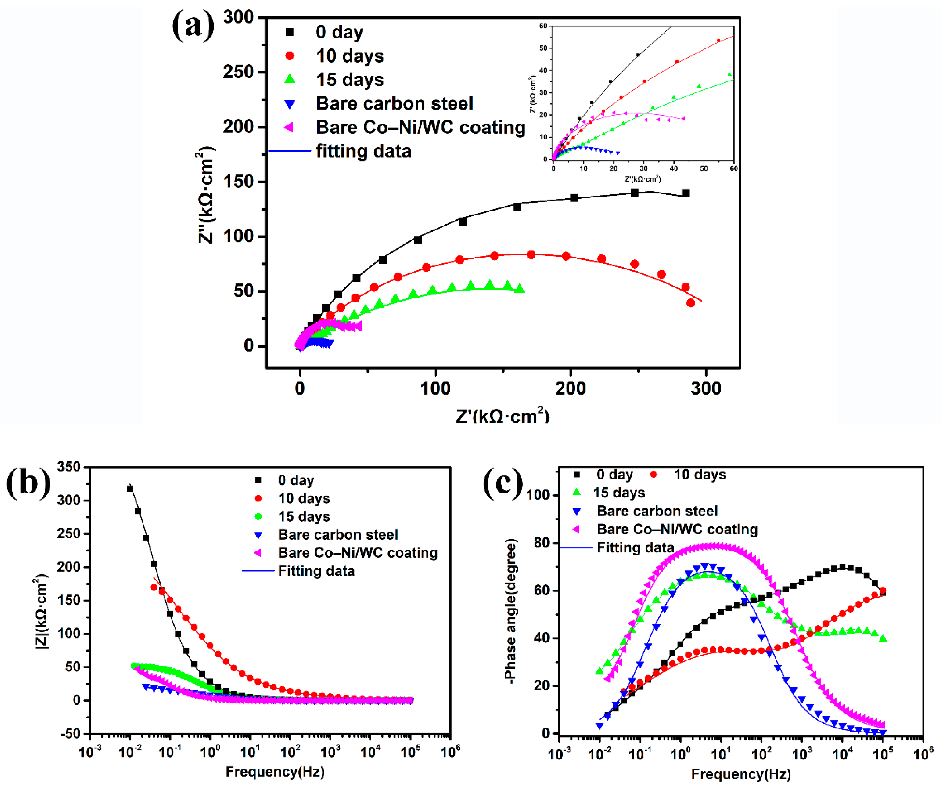
Figure 6 shows the EIS plots and their fitted results for the bare carbon steel, unmodified Co–Ni coating and Co–Ni SHPB coating immersed for 0 days, 10 days and 25 days. As shown in Figure 6a, the semicircle Nyquist plots of bare carbon steel show a typical behavior of solid metallic electrodes with the center below the real impedance axis. The Nyquist plot of the bare Co–Ni coating depicted a semicircle similar to the plot of bare carbon steel, and reflected a larger arc radius due to the barrier effect of the coating. In addition, Figure 6a also revealed the appearance of only one capacitive loop for the Co–Ni SHPB coatings before and after immersion, and the size of the capacitive loop gradually decreased as the immersion time increased. Generally, the better anti-corrosion ability of a coating corresponded to the larger size of the capacitive loop. Compared to the bare Co–Ni coating, the corrosion resistance of the Co–Ni SHPB coating gradually halved as the immersion time prolonged to 25 days, but was still one order of magnitude larger than the base material. The equivalent circuit shown in Figure 7a was proposed to fit the EIS plots of the bare Co–Ni coating, and the introduction of the Warburg impedance in Figure 7a achieved a more satisfactory fitting result. The equivalent circuit shown in Figure 7b was proposed to fit the EIS plots of the bare carbon steel, considering the influence of corrosion products, two parallel resistance and capacitance combinations of impedance were proposed to fit the EIS plots [28].
The impedance module and phase angle were given in the Bode diagram (Figure 6b,c). The impedance module Z (Figure 6b) for all samples shows a nearly linear slope in the low and middle frequency ranges, where the Co–Ni SHPB coating before immersion was as large as about 100 kΩ·cm2, higher than the Co–Ni SHPB coating after immersion and two orders of magnitude higher than that of the base material (1.21 kΩ·cm2). The phase angle plot (Figure 6c) shows only a one time-constant for the bare carbon steel (around 1 Hz) and Co–Ni coating without modification (around 10 Hz), which is associated with electrochemical activity and could be explained by the capacitance of the double layer on the solid/electrolyte interface. Obviously, the time-constant of the bare Co–Ni coating was shifted to a higher frequency than the base material, which could be attributed to the formation of the double-layer capacitance on the coating/electrolyte interface. Two time-constants could be observed for the Co–Ni SHPB coating after immersion for 0 days, 10 days and 25 days, and the time-constant at a low frequency was shifted to a lower frequency due to the decrease in the super-hydrophobicity as the immersion time was prolonged. The equivalent circuit in Figure 7b was proposed to fit the EIS plots of the bare carbon steel and Co–Ni SHPB coatings during the immersion process, where Rct and CPEdl corresponded to the charge transfer resistance and double layer capacitance occurring at the substrate/solution interface within a very small, corroded area, and Rc and CPEc corresponded to the coating resistance and double-layer capacitance at the substrate/coating interface, respectively. The symbol CPE indicates the possibility of a non-ideal capacitance, which is considered to be a description of the relaxation time associated with heterogeneities at the surface of the electrode. From the literature [28,37], the impedance of CPE is described as follows:
ZCPE = 1/Y0(jω)n
where ZCPE represents the impedance of a CPE, Y0 represents the modulus, ω represents the angular frequency and n is the exponent of the CPE varying between 0 and 1.
Based on the relevant equivalent circuits revealed in Figure 7, the electrochemical parameters of all samples were shown in Table 5. The solution resistance (Rs) remained stable for all tested samples after immersion in the NaCl solution, revealing a stable conductivity in the corrosive media. For the unmodified Co–Ni coating, the value of Rc was less than 10 Ω·cm2 when analyzed. Thus, the equivalent circuit could be simplified as the circuit in Figure 7a.
Before immersion, the Co–Ni SHPB coating displayed the highest charge transfer resistance value (Rct), representing the best corrosion resistance. The Rct value of the Co–Ni SHPB coating decreased from 648 to 42.8 and 9.45 kΩ·cm2 as the immersion time increased to 10 days and 25 days, corresponding to the decrease in non-wetting properties over the super-hydrophobic surface. Similarly, the Rc value of the SHPB Co–Ni coating decreased from 12.2 to 11.8 and 6.13 kΩ·cm2, with the increase in immersion time to 10 days and 25 days, which could be attributed to the degradation of the protective coating over the bare carbon steel substrate. In particular, when the immersion time reached 10 days, the Rct value dropped significantly, but the Rc value only dropped slightly, which indicated that the coating was not significantly damaged in the early stage of immersion. It was proven that the corrosion resistance of the super-hydrophobic coating was degraded due to the displacement of the air layer by the aqueous corrosive media.
Figure 8 shows the Nyquist plots and their fitted results of the bare carbon steel, bare Co–Ni/WC composite coating and Co–Ni/WC SHPB composite coating immersed for 0 days, 10 days and 15 days. The Nyquist plots of the bare Co–Ni/WC coating showed a weak Warburg impedance in the low-frequency range and a semicircle capacitive loop in the high-frequency range (Figure 8a). The Bode phase angle plots (Figure 8c) showed an asymmetric peak, and two peaks approximately around 1 Hz and 103 Hz were divided to correspond the composite coating and solution–substrate interface. Hence, an equivalent circuit (Figure 9a) was proposed, which included two capacitances and resistance in parallel and combined with the Warburg impedance to fit the EIS of the unmodified Co–Ni/WC coating. In this circuit, Rc was added to correspond the resistance of the Co–Ni/WC composite coating.
Similar to the plots of the Co–Ni SHPB coating, only one semicircle capacitive loop appeared in the Nyquist plots of the immersed composite coating (Figure 8a). The Bode module plot (Figure 8b) halved the impedance drop for the Co–Ni/WC SHPB composite coating after immersion for 10 days, and about a seven-times drop for the immersion time of 15 days. According to the Bode phase angle plots, two time-constants could be observed with two corresponding peaks at approximately 10 Hz and 105 Hz, where the time constant observed in high frequency was ascribed to the existence of the super-hydrophobic composite surface and the time constant observed in the intermediate frequency could be related to the corroding interface. The equivalent circuit (Figure 9b) characterized the corrosion principle of the super-hydrophobic coating before and after immersion in the NaCl solution, where Rs corresponded to the solution resistance, Rct and CPEdl were the charge transfer resistance and the double-layer capacitance occurring at the substrate/solution interface. The CPEc and Rc corresponded to the double-layer capacitance at the substrate/coating interface and the resistance of the Co–Ni/WC coating, respectively.
The electrochemical parameters shown in Table 6 clearly represented the surface conditions of the Co–Ni/WC SHPB coating during the immersion process. Rct represented the charge transfer resistance at the solution/substrate and an obvious decrease from 67.0 kΩ·cm2 to 44.5 kΩ·cm2 and 18.8 kΩ·cm2 as the immersion time increased to 10 days and 15 days. Similar results were observed from the CPEdl, where the value increased from 1.67×10⁻⁷ Ω−1·sn·cm−2 to 4.86×10⁻⁶ Ω−1·sn·cm−2 and 2.22×10⁻⁵ Ω−1·sn·cm−2. The increase in the CPEdl and decrease in the Rct indicated the protective effect of the inner layer having dropped gradually with the immersion time. Generally, the CPEdl reflects the dielectric behavior of the solution/coating interface, and CPEdl becomes C for n = 1. Furthermore, C = C0A, where C0 and A are the normalized capacitance and the exposed coating area, respectively [38]. The increase in the value of the CPEdl as the immersion time increased showed that A was enlarged, which was consistent with the changing of the coating morphology in 
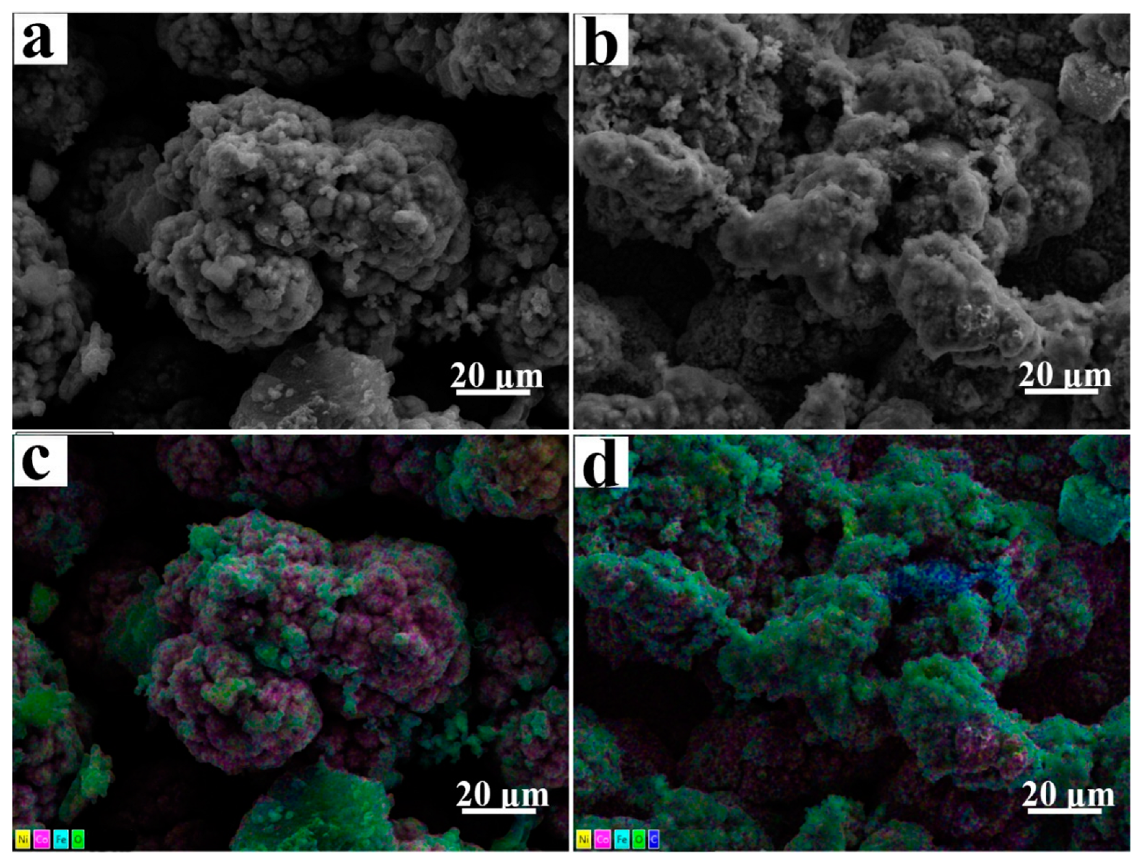
Figure 2. In particular, the coating resistance (Rc) for the Co–Ni/WC composite coating without modification reached 760 Ω·cm2, which was much more than the Co–Ni coating resistance due to the addition of second-phase particles (WC). Generally, the polarization resistance (Rp) always evaluates the total corrosion resistance, which was defined as a low-frequency limit of the electrode impedance and the frequency going to zero impedance of a capacitor to infinity. Therefore, Rp = Rc + Rct for circuits 9c, Rp = Rc for circuits 9a. When the SHPB Co–Ni/WC composite coating was immersed for 10 days, the Rp value decreased slightly. However, as the immersion time reached 15 days, the Rp value decreased by more than one order of magnitude, which was close to the bare Co–Ni/WC composite coating.
The corrosion protection mechanism provided by the Co–Ni/WC SHPB coating was shown in Figure 10. The air entrapped in the cauliflower-like structures could prevent the Co–Ni/WC composite coating from being wetted by the corrosive media through the limited solid contact area, endowing the coating with a larger charge transfer resistance and a lower corrosion rate, and then a better corrosion protection performance.
The long-term durability of the super-hydrophobic surface is a critical criterion in assessing their wide range applications. The stability of super-hydrophobic surfaces as engineering materials in corrosive media is crucial in many practical applications. Some literature has reported the stability of super-hydrophobic surfaces in different corrosive media, such as strong acid, strong alkali, pure water and 3.5% NaCl aqueous solutions. Zhang et al. fabricated super-hydrophobic (SHPB) surfaces by electrodeposition, and the prepared SHPB surfaces exhibited excellent chemical stability in pure water and corrosive water, such as acid and alkaline, conditions [39]. Zhang et al. reported a handy and versatile fabrication of nonfluorinated giganteum-like super-hydrophobic aluminum surfaces. The super-hydrophobic surfaces maintained super-hydrophobicity after an 8-month air exposure and a 12-day immersion under 3.5% NaCl aqueous solutions, respectively [40]. In our work, the as-prepared two kinds of robust coatings displayed a good long-term durability, whereas the Co–Ni SHPB coating and Co–Ni/WC SHPB composite coating lost their super-hydrophobicity over 10 days of immersion.

4. Conclusions

In this work, the long-term durability of two kinds of robust Co–Ni-based super-hydrophobic coatings was investigated by immersing in 3.5 wt.% NaCl solution.
1. The immersion tests showed that the two robust super-hydrophobic coatings had a long-term durability, where the Co–Ni super-hydrophobic coating lost its super-hydrophobicity after immersion for approximately 10 to 25 days, and the Co–Ni/WC super-hydrophobic coating lost its super-hydrophobicity after immersion for approximately 10 to 15 days.
2. The loss of super-hydrophobicity could be attributed to the corrosion damage of the micro–nano structures on the coating and the desorption of low surface energy materials. In the early stage of immersion, the desorption of the fluorine-containing hydrophobic groups occurred firstly. In the later stage, it appeared as corrosion damage of the micro–nano structures on the coatings.
3. Electrochemical tests illustrated the corrosion resistance of two kinds of super-hydrophobic coatings decreased with an increasing immersion time, which was mainly due to the replacement of air in the micro–nano structures by the NaCl solution. Even though the coatings lost their super-hydrophobicity, they still had a good corrosion resistance.
Therefore, two kinds of robust super-hydrophobic coatings may be potential candidates to face the harsh environments in practical applications.

Author Contributions

Data curation, S.W.; Formal analysis, S.W.; Writing—original draft, S.W.; Writing—review and editing, Y.X. (Yanpeng Xue), Y.J., Y.X. (Yanyan Xue) and C.L. All authors have read and agreed to the published version of the manuscript.

Funding

This work was supported by the National Key Research and Development Program of China (Grant No. 2017YFB0701904). The authors would also like to express thanks to the support from the 111 Project (Grant No. B12012) for promoting the international exchange.

Institutional Review Board Statement

Not applicable.

Informed Consent Statement

Not applicable.

Data Availability Statement

Data are contained within the article.

Acknowledgments

Yanpeng Xue thanks the support from the Fundamental Research Funds for the Central Universities China (Project ID: FRF-TP-20-049A2). Additionally, the project was also supported by the Tribology Science Fund of the State Key Laboratory of Tribology.

Conflicts of Interest

The authors declare no conflict of interest.

References

  1. Vazirinasab, E.; Jafari, R.; Momen, G. Application of superhydrophobic coatings as a corrosion barrier: A review. Surf. Coatings Technol. 2018, 341, 40–56. [Google Scholar] [CrossRef]
  2. Zhang, D.; Wang, L.; Qian, H.; Li, X. Superhydrophobic surfaces for corrosion protection: A review of recent progresses and future directions. J. Coatings Technol. Res. 2016, 13, 11–29. [Google Scholar] [CrossRef] [Green Version]
  3. Ruan, M.; Li, W.; Wang, B.; Deng, B.; Ma, F.; Yu, Z. Preparation and anti-icing behavior of superhydrophobic surfaces on aluminum alloy substrates. Langmuir 2013, 29, 8482–8491. [Google Scholar] [CrossRef] [PubMed]
  4. Liao, R.; Zuo, Z.; Guo, C.; Yuan, Y.; Zhuang, A. Fabrication of superhydrophobic surface on aluminum by continuous chemical etching and its anti-icing property. Appl. Surf. Sci. 2014, 317, 701–709. [Google Scholar] [CrossRef]
  5. Ge, M.; Cao, C.; Huang, J.; Zhang, X.; Tang, Y.; Zhou, X.; Zhang, K.; Chen, Z.; Lai, Y. Rational design of materials interface at nanoscale towards intelligent oil-water separation. Nanoscale Horiz. 2018, 3, 235–260. [Google Scholar] [CrossRef]
  6. Ma, Q.; Cheng, H.; Fane, A.G.; Wang, R.; Zhang, H. Recent development of advanced materials with special wettability for selective oil/water separation. Small 2016, 12, 2186–2202. [Google Scholar] [CrossRef]
  7. Dong, H.; Cheng, M.; Zhang, Y.; Wei, H.; Shi, F. Extraordinary drag-reducing effect of a superhydrophobic coating on a macroscopic model ship at high speed. J. Mater. Chem. A 2013, 1, 5886–5891. [Google Scholar] [CrossRef]
  8. Liu, K.; Jiang, L. Metallic surfaces with special wettability. Nanoscale 2011, 3, 825–838. [Google Scholar] [CrossRef]
  9. Ma, N.; Chen, Y.; Zhao, S.; Li, J.; Shan, B.; Sun, J. Preparation of super-hydrophobic surface on Al–Mg alloy substrate by electrochemical etching. Surf. Eng. 2019, 35, 394–402. [Google Scholar] [CrossRef]
  10. Long, J.; Fan, P.; Gong, D.; Jiang, D.; Zhang, H.; Li, L.; Zhong, M. Superhydrophobic surfaces fabricated by femtosecond laser with tunable water adhesion: From lotus leaf to rose petal. ACS Appl. Mater. Interfaces 2015, 7, 9858–9865. [Google Scholar] [CrossRef]
  11. Boinovich, L.B.; Modin, E.B.; Sayfutdinova, A.R.; Emelyanenko, K.A.; Vasiliev, A.L.; Emelyanenko, A.M. Combination of functional nanoengineering and nanosecond laser texturing for design of superhydrophobic aluminum alloy with exceptional mechanical and chemical properties. ACS Nano 2017, 11, 10113–10123. [Google Scholar] [CrossRef] [PubMed]
  12. Yu, J.; Qin, L.; Hao, Y.; Kuang, S.; Bai, X.; Chong, Y.M.; Zhang, W.; Wang, E. Vertically aligned boron nitride nanosheets: Chemical vapor synthesis, ultraviolet light emission, and superhydrophobicity. ACS Nano 2010, 4, 414–422. [Google Scholar] [CrossRef] [PubMed]
  13. Yanpeng, X.; Taleb, A.; Jegou, P. Electrodeposition of cobalt films with an oriented fir tree-like morphology with adjustable wetting properties using a self-assembled gold nanoparticle modified HOPG electrode. J. Mater. Chem. A 2013, 1, 11580–11588. [Google Scholar] [CrossRef]
  14. Xue, Y.; Wang, S.; Zhao, G.; Taleb, A.; Jin, Y. Fabrication of Ni–Co coating by electrochemical deposition with high super-hydrophobic properties for corrosion protection. Surf. Coatings Technol. 2019, 363, 352–361. [Google Scholar] [CrossRef]
  15. Lee, M.; Kwak, G.; Yong, K. Wettability control of ZnO nanoparticles for universal applications. ACS Appl. Mater. Interfaces 2011, 3, 3350–3356. [Google Scholar] [CrossRef] [PubMed]
  16. Darmanin, T.; De Givenchy, E.T.; Amigoni, S.; Guittard, F. Superhydrophobic surfaces by electrochemical processes. Adv. Mater. 2013, 25, 1378–1394. [Google Scholar] [CrossRef] [PubMed]
  17. Tam, J.; Palumbo, G.; Erb, U. Recent advances in superhydrophobic electrodeposits. Materials 2016, 9, 151. [Google Scholar] [CrossRef] [PubMed] [Green Version]
  18. Lu, Y.; Sathasivam, S.; Song, J.; Crick, C.R.; Carmalt, C.J.; Parkin, I.P. Robust self-cleaning surfaces that function when exposed to either air or oil. Science 2015, 347, 1132–1135. [Google Scholar] [CrossRef]
  19. Tian, X.; Verho, T.; Ras, R.H.A. Moving superhydrophobic surfaces toward real-world applications. Science 2016, 352, 142–143. [Google Scholar] [CrossRef]
  20. Zou, Y.; Wang, Y.; Xu, S.; Jin, T.; Wei, D.; Ouyang, J.; Jia, D.; Zhou, Y. Superhydrophobic double-layer coating for efficient heat dissipation and corrosion protection. Chem. Eng. J. 2019, 362, 638–649. [Google Scholar] [CrossRef]
  21. Xue, Y.; Wang, S.; Bi, P.; Zhao, G.; Jin, Y. Super-hydrophobic Co-Ni coating with high abrasion resistance prepared by electrodeposition. Coatings 2019, 9, 232. [Google Scholar] [CrossRef] [Green Version]
  22. Xue, Y.; Wang, S.; Xue, Y.; Cao, L.; Nie, M.; Jin, Y. Robust self-cleaning and marine anticorrosion super-hydrophobic Co–Ni/CeO2 Composite Coatings. Adv. Eng. Mater. 2020, 22, 2000402. [Google Scholar] [CrossRef]
  23. Tam, J.; Jiao, Z.; Lau, J.C.F.; Erb, U. Wear stability of superhydrophobic nano Ni-PTFE electrodeposits. Wear 2017, 374, 1–4. [Google Scholar] [CrossRef]
  24. Pezzato, L.; Vranescu, D.; Sinico, M.; Gennari, C.; Settimi, A.G.; Pranovi, P.; Brunelli, K.; Dabalà, M. Tribocorrosion properties of PEO Coatings produced on AZ91 magnesium alloy with silicate- or phosphate-based electrolytes. Coatings 2018, 8, 202. [Google Scholar] [CrossRef] [Green Version]
  25. Yu, N.; Xiao, X.; Ye, Z.; Pan, G. Facile preparation of durable superhydrophobic coating with self-cleaning property. Surf. Coatings Technol. 2018, 347, 199–208. [Google Scholar] [CrossRef]
  26. Su, F.; Yao, K. Facile fabrication of superhydrophobic surface with excellent mechanical abrasion and corrosion resistance on copper substrate by a novel method. ACS Appl. Mater. Interfaces 2014, 6, 8762–8770. [Google Scholar] [CrossRef]
  27. Vanithakumari, S.C.; George, R.P.; Kamachi Mudali, U. environmental stability and long-term durability of superhydrophobic coatings on titanium. J. Mater. Eng. Perform. 2017, 26, 2640–2648. [Google Scholar] [CrossRef]
  28. Wang, P.; Li, T.; Zhang, D. Fabrication of non-wetting surfaces on zinc surface as corrosion barrier. Corros. Sci. 2017, 128, 110–119. [Google Scholar] [CrossRef]
  29. Society, T.R. Hydrogen overvoltage and the reversible hydrogen electrode. Proc. R. Soc. London. Ser. A Math. Phys. Sci. 1936, 157, 423–433. [Google Scholar] [CrossRef]
  30. Bockris, J.O.M.; Reddy, A.K.N. Modern Electrochemistry; Plenum Press: New York, NY, USA, 1977; Volume 2, p. 883. [Google Scholar]
  31. Tafel, J. Über die Polarisation bei kathodischer Wasserstoffentwicklung. Z. Für Phys. Chem. 1905, 50, 641–712. [Google Scholar] [CrossRef]
  32. Mazare, A.; Totea, G.; Burnei, C.; Schmuki, P.; Demetrescu, I.; Ionita, D. Corrosion, antibacterial activity and haemocompatibility of TiO2 nanotubes as a function of their annealing temperature. Corros. Sci. 2016, 103, 215–222. [Google Scholar] [CrossRef]
  33. Kear, G.; Walsh, F.C. The characteristics of a true Tafel slope. Corros. Mater. 2005, 30, 51–55. [Google Scholar]
  34. Burstein, G.T. A hundred years of Tafel’s Equation: 1905–2005. Corros. Sci. 2005, 47, 2858–2870. [Google Scholar] [CrossRef]
  35. Zhang, X.L.; Jiang, Z.H.; Yao, Z.P.; Song, Y.; Wu, Z.D. Effects of scan rate on the potentiodynamic polarization curve obtained to determine the Tafel slopes and corrosion current density. Corros. Sci. 2009, 51, 581–587. [Google Scholar] [CrossRef]
  36. McCafferty, E. Validation of corrosion rates measured by the Tafel extrapolation method. Corros. Sci. 2005, 47, 3202–3215. [Google Scholar] [CrossRef]
  37. Wang, S.; Xue, Y.; Ban, C.; Xue, Y.; Taleb, A.; Jin, Y. Fabrication of robust tungsten carbide particles reinforced Co–Ni super-hydrophobic composite coating by electrochemical deposition. Surf. Coatings Technol. 2020, 385, 125390. [Google Scholar] [CrossRef]
  38. Yao, Z.; Jiang, Z.; Xin, S.; Sun, X.; Wu, X. Electrochemical impedance spectroscopy of ceramic coatings on Ti-6Al-4V by micro-plasma oxidation. Electrochim. Acta 2005, 50, 3273–3279. [Google Scholar] [CrossRef]
  39. Zhang, B.; Li, J.; Zhao, X.; Hu, X.; Yang, L.; Wang, N.; Li, Y.; Hou, B. Biomimetic one step fabrication of manganese stearate superhydrophobic surface as an efficient barrier against marine corrosion and Chlorella vulgaris-induced biofouling. Chem. Eng. J. 2016, 306, 441–451. [Google Scholar] [CrossRef]
  40. Zhang, B.; Zhu, Q.; Li, Y.; Hou, B. Facile fluorine-free one step fabrication of superhydrophobic aluminum surface towards self-cleaning and marine anticorrosion. Chem. Eng. J. 2018, 352, 625–633. [Google Scholar] [CrossRef]
Figure 1. Wettability variations (WCA, WSA) of (a) Co–Ni SHPB coatings and (b) Co–Ni/WC SHPB composite coatings with the time of immersion in 3.5 wt.% NaCl solution.
Coatings 12 00222 g001
Figure 2. Microstructure evolution for coatings immersed in 3.5 wt.% NaCl solution. Co–Ni SHPB coating: (a) immersed for 0 days; (b) immersed for 10 days; (c) immersed for 25 days; Co–Ni/WC SHPB composite coating: (d) immersed for 0 days; (e) immersed for 10 days; (f) immersed for 15 days. The insets show the corresponding cross-section.
Coatings 12 00222 g002
Figure 3. SEM images and EDS elemental distribution mappings immersed in 3.5 wt.% NaCl solution. (a,c) Co–Ni SHPB coatings for 25 days and (b,d) Co–Ni/WC SHPB composite coatings for 15 days.
Coatings 12 00222 g003
Figure 4. XPS spectra of the coatings after immersion for different days. Co–Ni SHPB coating: (a) total survey spectra; (b) high-resolution C 1s spectra; (c) F 1s spectra. Co–Ni/WC SHPB coating: (d) total survey spectra; (e) high-resolution C 1s spectra; (f) F 1s spectra.
Coatings 12 00222 g004
Figure 5. Polarization curves of (a) bare carbon steel, Co–Ni SHPB coating and coating after being immersed for 25 days and (b) bare carbon steel, Co–Ni/WC SHPB coating and coating after being immersed for 15 days; magnified example of the anodic Tafel plots of (c) bare carbon steel, Co–Ni SHPB coating and coating after being immersed for 25 days and (d) bare carbon steel, Co–Ni/WC SHPB coating and coating after being immersed for 15 days.
Coatings 12 00222 g005
Figure 6. EIS results of the bare carbon steel, bare Co–Ni coating and Co–Ni SHPB coating immersion for 0 days, 10 days and 25 days: (a) Nyquist plots; (b) Bode-|Z| versus frequency plots and (c) Bode-phase angle versus frequency plots.
Coatings 12 00222 g006
Figure 7. Equivalent circuits of (a) bare Co–Ni coating, (b) bare carbon steel and Co–Ni SHPB coating before and after immersion.
Coatings 12 00222 g007
Figure 8. The EIS plots of the bare carbon steel, bare Co–Ni/WC coating and Co–Ni/WC SHPB coating before and after immersion: (a) Nyquist plots; (b) Bode-|Z| versus frequency plots and (c) Bode phase angle versus frequency plots.
Coatings 12 00222 g008
Figure 9. Equivalent circuits of (a) bare Co–Ni/WC coating; (b) bare carbon steel and Co–Ni/WC SHPB coating before and after immersion.
Coatings 12 00222 g009
Figure 10. The corrosion protection mechanism provided by Co–Ni/WC SHPB coating.
Coatings 12 00222 g010
Table 1. The EDS results of the Co–Ni SHPB coating immersed for 0 days, 10 days and 25 days.
Co–Ni CoatingCo (wt.%)Ni (wt.%)O (wt.%)Fe (wt.%)
Immersion for 0 days78.221.8--
Immersion for 10 days83.313.51.71.5
Immersion for 25 days85.111.21.91.8
Table 2. The EDS results of the Co–Ni/WC SHPB composite coating immersed for 0 days, 10 days and 15 days.
Co–Ni CoatingCo (wt.%)Ni (wt.%)O (wt.%)Fe (wt.%)WC (wt.%)
Immersion for 0 days69.021.2--9.8
Immersion for 10 days48.612.08.626.44.4
Immersion for 25 days41.08.211.136.43.3
Table 3. Corrosion parameters of Co–Ni SHPB coating fitted from the polarization curves.
SampleEcorr (mV)jcorr (μA/cm2)ba (mV·dec−1)−bc (mV·dec−1)
Bare carbon steel−459.4 ± 5.514.5 ± 0.5 156 ± 6.5206 ± 7
Immersion for 25 days−401.4 ± 6.15.06 ± 0.478 ± 7.198 ± 2.1
SHPB Co–Ni coating−286.3 ± 5.20.629 ± 0.0673 ± 4.475 ± 4.3
Table 4. Corrosion parameters of Co–Ni/WC SHPB coating fitted from the polarization curves.
SampleEcorr (mV)jcorr (μA/cm2)ba (mV·dec−1)−bc (mV·dec−1)
Bare carbon steel−459.4 ± 5.514.5 ± 0.5156 ± 6.5206 ± 7
Immersion for 15 days−303.1 ± 3.73.06 ± 0.3103 ± 4.3109 ± 3.3
SHPB Co–Ni/WC coating−256.4 ± 4.20.149 ± 0.0775 ± 6.769 ± 2.7
Table 5. The EIS parameters of bare carbon steel, unmodified Co–Ni coating and Co–Ni SHPB coating before and after immersion.
Fitted parametersRSCPEdlndlRctCPEcncRcZwChi-Squared
Bare carbon steel7.934.35 × 10–40.71441.995.47 × 10–40.744224.01-4.964 × 10⁻⁴
Bare Co–Ni coating7.648.10 × 10–50.85342.571.94 × 10–40.5971-0.00819.358 × 10–4
Immersion for 0 days12.931.63 × 10–60.68376481.41 × 10–60.880312.2 × 10–3-9.957 × 10⁻⁵
Immersion for 10 days13.639.36 × 10–60.788742.83.72 × 10–50.727011.8 × 10–3-6.955 × 10⁻⁴
Immersion for 25 days11.809.75 × 10–60.82379.451.88 × 10–50.51156.13 × 10–3-3.991 × 10⁻⁴
Note: The units of Rs, Rct, Rc, Zw and CPE are Ω·cm2, kΩ·cm2, Ω·cm2, Ω−1·s0.5·cm−2·10−3 and Ω−1·sn·cm−2, respectively.
Table 6. The EIS parameters of bare carbon steel, unmodified Co–Ni/WC composite coating and Co–Ni/WC SHPB composite coating before and after immersion.
Fitted ParametersRSCPEdlndlRctCPEcncRcZwRpChi-Squared
Bare carbon steel7.934.35 × 10–40.71441.995.47 × 10–40.744224.01-2.354.964 × 10–4
Bare Co–Ni/WC coating9.082.49 × 10–50.10339.564.75 × 10–50.92620.76 × 10–30.003-1.241 × 10⁻³
Immersion for 0 days12.901.67 × 10–70.673267.01.41 × 10–60.4803440.08 × 10–3-507.082.740 × 10–4
Immersion for 10 days14.804.86 × 10–60.678144.54.31 × 10–60.7854426.23 × 10–3-470.731.076 × 10–3
Immersion for 15 days12.932.22 × 10–50.672418.87.71 × 10–40.97153.04 × 10–3-21.849.949 × 10–4
Note: The units of Rs, Rct, Rc, Rp, Zw and CPE are Ω·cm2, kΩ·cm2, Ω·cm2, kΩ·cm2, Ω−1·s0.5·cm−2·10−3 and Ω−1·sn·cm−2, respectively.
Publisher’s Note: MDPI stays neutral with regard to jurisdictional claims in published maps and institutional affiliations.

