Article

On Variable Scale Evolution of Stress and Strain of TA2 Titanium Plate in Combined Hammering

School of Mechanical and Instrument Engineering, Xi’an University of Technology, Xi’an 710048, China
*
Author to whom correspondence should be addressed.
Coatings 2022, 12(12), 1974; https://doi.org/10.3390/coatings12121974
Submission received: 12 November 2022 / Revised: 8 December 2022 / Accepted: 14 December 2022 / Published: 16 December 2022
(This article belongs to the Special Issue Surface Treatment for Metals and Alloys)

Abstract

:
Combined peening composed of multiple peening processes or peening media is a surface treatment method for comprehensive control of the macro shape and performance of the part. Compared to combined peening, the impact kinetic energy of the combined hammering can be easier to control over a wide range, and the hammer tool head size is larger than the shot. This paper focused on investigating the effect of combined hammering treatment, 6 mm and 14 mm tool heads with peening density 3.7 to 4.2/mm 2 , on the variable scale evolution of titanium TA2. Three types of contact relation between the tool head and existing dimple were proposed for impacting at the same position. The size of the dimple of combined hammering varies in width or depth direction, resulting in nest morphology composed of different size dimples. The cross-section microstructure of the test plate was observed, and the gradient changes of dislocation, slip, and grain size are smoothed by combined hammering. The change in hammer tool head size makes the target plastic deform at different depths. The hammering sequence has a significant influence on the evolution of stress and strain fields. When the tool head is first large and then small, a large compressive residual stress near the surface is introduced, about 1000 Mpa; on the contrary, the compressive residual stress distributes uniformly in the depth direction, with an affected layer depth of about 4.4 mm. The measured dimple size and residual stress verified the reliability of the simulation results.

1. Introduction

Titanium and titanium alloy materials are widely applied in aviation, aerospace, navigation, chemical, and medical fields because of their multiple benefits, including specific strength, heat resistance, high chemical stability, high biocompatibility, and low weight [1,2]. Some Ti-based particulates or coatings can enhance the mechanical behavior of components [3,4]. To form large-size thin-walled titanium and titanium alloy components, and to improve their wear resistance and fatigue resistance depends on surface processing [5,6], shot peening is one of the effective surface processes [7].
Shot peening process can create residual stress on the surface of components, refine grain, increase dislocation density, etc.; in addition, it can change the surface morphology of parts to control macroscopic deformation and improve fatigue resistance [8,9]. The residual stress field, microstructure, and surface morphology formed by the shot peening can be collectively referred to as the functional field, so a different meaning of morphology production requests a different functional field through the shot peening. In the shot peening process of the wall parts, it requests a specific non-uniform distribution of the shot peening functional field [10] which can be controlled by residual stress due to the complex target surface, structural stiffness changes and non-uniform wall thickness distribution, and other characteristics [11]. When a component needs both forming and strengthening, it often uses a combined process such as two or more methods of shot peening or multiple balls to meet a variety of macroscopic regulatory purposes.
For a long time, combined shot peening has been used in actual engineering. It considers the different processes which occur before and after as mutual independence, and the combined effects have been neglected, it is hard to control the process, identify the improvement from the combined shot peening, and precisely predict. In recent years, many scholars have observed the relative benefits of combined shot peening; compared with the processing of the single parameters, the component experiencing combined peening has the finest comprehensive performance, relatively [12]. The hybrid processing sequences of laser shot peening and conventional shot peening have certain effects on the uniformity and stability of surface residual stress [13]; the satisfactory combinations of them have a series of effects such as increasing residual stress, increasing surface hardness and thickness of hardened layer [14], refining the surface grain size of the target material, multiplying dislocation density; hence, the fatigue strength of the material can be improved [15]. Using steel peening balls of various sizes and materials can lower the roughness of the shot-peened surface and raise the uniformity of the residual stress field, etc. [16]. The shot hardness influences the value and depth of the residual stress, to obtain the high residual stress value on the surface with the remaining depth, the double shot peening with the sequence of the first larger shots and then the high hardness media with compatible size had been suggested [17].
The combined shot peening process can reconcile the contradiction between the requirements of strong-plastic deformation and surface roughness, residual stress field management ability and processing efficiency, non-uniform stress field, and uniform strengthening layer. Compared to the combined shot peening, combined hammering offers the advantage of larger kinetic energy and the size of hammer tool head that is larger than the shot used in the conventional shot peening, and importantly, more controllable. However, there is still a lack of work focusing on the effect of the combination hammering treatment on the variable scale evolution. Therefore, it is worth studying the effect of the combined hammering treatment on the variable scale evolution of stress and strain.
The paper focuses on the variable evolution of the strain and stress of the TA2 titanium plate after combined hammering treatment. The macrostructure at the cross section, and the residual stress distribution at surface and different depths were analyzed for specimens after different processing sequences with three types of contact relations between the hammering tool and the original dimple, which was barely proposed. The microstructure varieties in the subsurface layer of specimens after combined hammering were investigated by x-ray diffraction (XRD) and electrolytic corrosion method. Furthermore, the FEM-based values were validated in the experiment on the influence of combined treatment.

2. Combined Hammer Peening Experiments

The experiments were performed on pure titanium TA2 plates with dimensions of 100 mm × 50 mm × 10 mm, the material’s chemical composition is shown in Table 1. To relieve the residual stress introduced by plate rolling and homogenize its microstructure, a vacuum annealing treatment at 680 °C with 120 min was completed using a ZM series vacuum molybdenum wire furnace (vacuum degree 1 × 10 3 Pa), and a grinder was used to remove the oxide layer on the surface of the annealed test plate. The surface microstructure of the test plate before and after annealing treatment is shown in Figure 1. After annealing, the uniform grain size is about 100 μm and equiaxed. The Hollomon constitutive model for pure titanium (TA2) at room temperature is shown as follows [18]:
σ = 811.25 ε 0.1113 ε ˙ 0.02375
where σ and ε are, respectively, the effective stress and effective strain, and ε ˙ is the effective strain rate.
The Hammer peening process, as illustrated in Figure 2, uses a self-made electric hammer process system comprised of an electric hammer, bracket, frequency converter, and fixture. Inside the electric hammer, the air pressure piston powered by the motor strikes the push hammer to force the deputy hammer, causing the deputy hammer to affect the punch tool to impact the test specimen with a certain kinetic energy, and changing the hammer tool can alter the size of the tool head. The bracket keeps the electric hammer in a specific posture and controls the speed of the electric hammer in the plane during machining; the frequency converter outputs alternating current at a certain frequency to control the speed of the motor, and then regulates the impact kinetic energy; the fixture holds the test plate to maintain its fixed position and initial shape.
The material of hammer tool head is medium carbon steel for its good strong overall performance and higher strength and hardness than TA2 when applied in the condition of alternating load. It is suitable for TA2 processing. The tool head diameter D t o o l used in this work are 6 mm and 14 mm, respectively, with impact frequencies of 20 Hz and 28 Hz. Each group of test plates will be hammer-peened twice in a row, with the processing duration controlling the density of peening n c . The processing parameters for the four groups of test plates are shown in Table 2. The density of peening and impact dimple radius of projection a are used to calculate the shot peening coverage rate C p e e n :
C p e e n = 1 e π a 2 n c
The average impact dimple projection radius of a6 and a14, which made by 6 mm and 14 mm tool head with 20 Hz impact frequency, was 0.904 mm and 1.369 mm, respectively, based on the experiment data. According to the calculations, each hammer peening in the four groups of tests reached complete coverage. When the mass of D6 hammer tool is 420.78 g and the impact frequency is 20 Hz, the impact velocity is 1191 mm/s; when the mass of D14 hammer tool is 405.66 g and the impact frequency is 28 Hz, the velocity is 1768 mm/s.
After the experiment, the surface morphology of hammer peening was observed by a low-power microscope. The 10 mm × 10 mm × 10 mm cross-section sample was cut by Wire cut Electrical Discharge Machining (WEDM). The sample’s cross-section was lapped by Surface Mechanical Attrition Treatment (SMAT), polished and corroded, and the microstructure was inspected by a high-power microscope. The residual stress introduced by hammer peening at various depths was measured using X-ray diffraction and electrolytic corrosion method.

3. Finite Element Simulation of Combined Hammer Shot Peening

The simulation settings based on ABAQUS2020 finest simulation software match the test parameters, as shown in Figure 3, and a quarter symmetry analysis model of composite hammer simulation was constructed.
The target material quarter model size was 8 mm × 8 mm × 10 mm, and the size tapered from the impact point to the distal end; the impact point element was the smallest, with a side length of 0.1 mm; the distal end element was the largest, with the side length of 0.5 mm; and the target was mashed with 8-node reduced integration element (C3D8R), the mesh size is shown in Figure 3c The target material density was 4.507 g/cm 3 , the elastic modulus was 116 GPa, and Poisson’s ratio was 0.32, the constitutive parameter as given in Equation (1).
The hammer tool was simplified as a quarter ball head, the size of the ball head was the same as the size of the hammer tool head in the test, the mass of the ball head was the same as the mass of the hammer tool, the ball head was regarded as an elastic deformation body, the material elastic modulus was 210 GPa, and Poisson’s ratio was 0.33. The symmetry constraint was applied on the symmetry surface of the ball head and the target material. Meanwhile, the normal displacement of the nodes on the bottom surface of the target material was constrained.
The model was divided into two types: Type V, which the small-sized ball head hits the target material first and the large-sized ball head hits the target material afterward, the numbers of repeated impacts of the large ball and the small ball heads were 1, 2, 3 and 4, respectively; and Type A, which the impact ranking is the inverse of Type V. The specific impact parameters are listed in Table 3. The friction coefficient between the ball head and the target material was set at 0.1, indicating rigid contact. There was no contact relationship between the ball heads; hence, the dynamic implicit solution was selected.

4. Results and Discussion

4.1. The Hammer Peening Surface

According to the simulation and experimental analysis, there was a variable scale evolution of the dimple morphology during the combined hammer peening process with various sizes of the tool head. Three sorts of contact relationships between the tool head and the existing dimple while hammering continuously at the same spot, as shown in Figure 4. S i 1 r e s is the dimpled surface generated after the i-1th hammering, and the h i 1 is the dimple depth (with the initial surface of the plate as the reference plane); S i i n d is the dimple depth at the ith hammering when the piston moved to the bottom dead center, the actual depth of dimple is marked as H i , the tool head press-in depth is d i , and the diameter of tool head is D i , thus the dimple projection radius can be calculated by a i = D i d i d i 2 . According to the relationship between a i , a i 1 and d i , h i 1 , three types of typical contact relations were determined.
(1) Type V 1 : a i > a i 1 and d i > h i 1 . The projected radius of the tool head pressed into the boundary is larger than the projected radius of the original dimple, and the pressed-in depth is deeper than the original dimple depth, which is the type V 1 contact relationship. This type of contact happens when the curvature of the original dimple is similar to the curvature of the tool head, as shown in Figure 5.
(2) Type V 2 : a i > a i 1 and d i h i 1 . The projected radius of the tool head pressed into the boundary is larger than the projected radius of the original dimple, and the pressed-in depth is shallower than or equal to the original dimple depth, reflecting a type V 2 contact relationship. As shown in Figure 5, the D6 tool head repeatedly impacts to form a deeper dimple, and this type of contact occurs when the D14 tool head impacts again; the re-impact of the D14 tool head reduces the dimple curvature, and the subsequent re-impact may become a V 1 type of contact relationship.
(3) Type A: a i a i 1 . Type A contact relationship exists when the theoretical projected radius of the tool head pressed into the boundary is less than or equal to the projected radius of the original dimple. This type of contact occurs when the impact of the D14 tool head creates a dimple with greater curvature and the D6 tool head, which has the smaller curvature impacts again.
In the Type V 2 contact relationship, the tool head cannot touch the original dimple vertex; in Type V 1 contact relationship, although the tool head is pressed in deeper than the original dimple depth, the tool head may also fail to touch the original dimple vertex due to z-directional displacement of the target material. As shown in Figure 6a, the Type V simulation found that there was no gap between the tool head and the original dimple only in the first stage of D6 repeated impacts, and there was always a gap between the tool head and the original dimple in the second stage of D14 tool head impacts, but the gap gradually decreased as of the number of impacts increased in the subsequent stages.
The combined impacts of different size tool heads complicate the dimple morphology. It can be found that the repeated impacts of the same size tool head gradually increased the radius and depth of the dimple projection, as shown in Figure 5a and Figure 6b; the impacts of the small tool head followed by the impacts of the large tool head mainly increased the radius of the dimple projection while changing its depth less; the impacts of the small tool head followed by the impacts of the large tool head had little effect on the radius of the dimples but the dimples became significantly deeper, resulting in nest morphology with different curvature dimples. As illustrated in Figure 7, the surface topography of the test pieces confirms the above rules and characteristics. The simulated radius of the crater projection was consistent with the experimental observation, as shown in Figure 5.

4.2. Surface Microstructure

The four groups of hammering processing parameters were processed independently, and the microstructure of the surface section of the specimen is depicted in Figure 8. As can be noticed, the large-sized equiaxial grains in the surface layer were refined and formed the nano-crystalline, subgrain, coarse grain, and matrix layers, which were distributed in the depth direction. The multiple deformation layers were interlaced with each other without a clear boundary.
The nano-crystalline layer is dark black with no coarse grains; the subgrain layer has a small number of grains with shapes and boundaries, distributed with a large number of slip bands, dislocations, and twin crystals; the coarse grain layer has a certain number of grains with regular shapes, the grain size has not changed significantly and is still equiaxed, with a small number of slip bands and dislocations inside the grains; the structure of the matrix layer basically maintains the original organization after vacuum annealing.
Because of the plastic deformation layer, the thickness of nano-crystalline and subgrain layers of specimen 2 processed by D6 tool head is relatively thin; the gradient changes of dislocation and slip density of specimen 3 and specimen 4 processed by the composite of two sizes of tool heads are smoother compared with specimen 1, showing the excellent ability of combined hammering processing to regulate the gradient of microstructure. A multistage microstructure for metallic materials with a gradient distribution along the depth direction can provide excellent strength-plasticity matching [19]. A combination of large and small shot peening processes can also obtain good surface quality and grain refinement layer, which can improve the specimen’s fatigue strength [20].

4.3. Stress-Strain Field Evolution

The composite hammering stress-strain field was obtained by simulation and the hammering residual stress was measured experimentally, and this section compares and analyzes the influence of hammering parameters on the stress-strain field of the target material. As shown in Figure 9, the equivalent plastic strain on the centerline of the hammering simulation model, and the impact order of the large and small tool heads have a significant effect on the plastic strain field, the plastic deformation zone of the large tool head hammering is deeper, but the plastic strain amplitude is lower; the plastic deformation zone of the small tool heads hammering is shallower, but the plastic strain amplitude is higher. There are a wide variety of peening methods and media, and the most critical parameter for controlling the peening effect in terms of a single impact is the radius of the surface on which the peening media was loaded, and the initial kinetic energy of the peening media [21].
Repeated hammering at the same position has a certain influence on both the plastic deformation depth and its strain amplitude, as seen in Figure 10, this influence diminishes as the number of repeated times increases. The shaded area in Figure 4 indicates the volume B i of the target material extruded by the tool head at the ith impact to the bottom dead center, which can be calculated by integrating B i = b i 2 π x d b i , and the calculation result of B i during the combined hammering is shown in Figure 11.
It can be seen that when the tool head size changes, the volume B i of the extruded material changes abruptly, and the equivalent plastic strain field is in Figure 10 changes abruptly accordingly; due to the influence of the existing dimples and residual stress-strain field, the extruded volume B i is slightly smaller at the time of abrupt change, gradually becomes larger and tends to a stable value then, and the equivalent plastic strain field in Figure 10 gradually tends to a stable value as well; based on small dimples, the material flows more easily when the large size tool head impacts on; as the small size tool head impacts on the large dimples, the material flows slightly more difficult when compared to the impact on a flat target material.
With the plastic deformation of the target surface layer, the residual stress field is formed in the target, as shown in Figure 12, and the change law of the residual stress field is similar to that of the equivalent plastic strain. The residual stress field formed by Big+Small tool head impact is bigger but shallower (1000 MPa, affected depth 3.2 m), whereas that formed by Small+Big tool head impact is smaller but deeper (750 MPa, affected depth 3.5 mm). Repeated impacts at the same location have less effect on the residual stress field amplitude, as shown in Figure 13, and when a certain shot peening coverage is reached, saturation has been achieved in term of residual stress field [22], but continued shot peening still has an effect on the microstructure evolution of the target material [23].
It has also been found that increasing the machining of the smaller tool head following the impact of the big tool head results in the higher and deeper residual compressive stress. Such a combination can also reduce the machining surface roughness, which is a combination used more. The fundamental concept is as same as the composite impact principle of employing a big and then a small tool head: first using laser shot peening to form deeper residual compressive stresses, and then using shot peening to increase the residual compressive stress amplitude near the surface [15]. The present research hot point is the combination of laser shot peening and conventional shot peening, since its forming ability and strengthening effects by peening are better [14].
After the big tool head impact, the residual compressive stress peak generated by the small tool head was lowered, but a greater surface compressive stress was formed, the depth of the compressive stress field grew and the uniformity improved. The stress field changes respectively in distinct depth regions throughout the combined hammering process, showing variable scale evolution features and increased complexity of the stress field.
The residual stresses in the specimens were measured by X-ray diffraction and electrolytic corrosion methods, and the measurement errors were largely due to the appearance of several diffraction peaks of the crystal plane in the X-ray diffraction stress measurement of titanium and titanium alloys, as shown in Figure 12. However, the residual stress field simulated by hammering was basically consistent with the measured value, which verified the simulation’s accuracy.

5. Conclusions

  • The experiments and finite element simulation were used to analyze the process of combined hammer peening. The variable-scale evolution characteristics of functional fields, such as stress and strain fields of the combined shot peening, surface morphology, and microstructure, were proposed. The surface is characterized by a nest morphology consisting of varied size dimples, the stress-strain field by successive evolution of different depth areas, and the microstructure by significant gradient change.
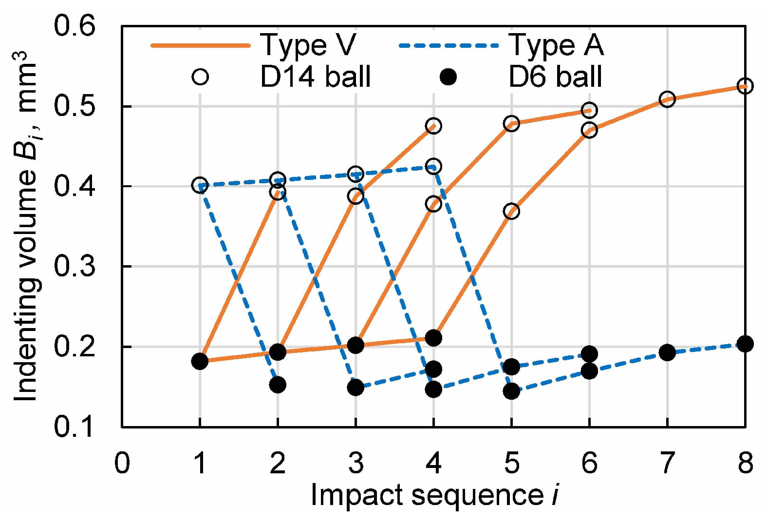
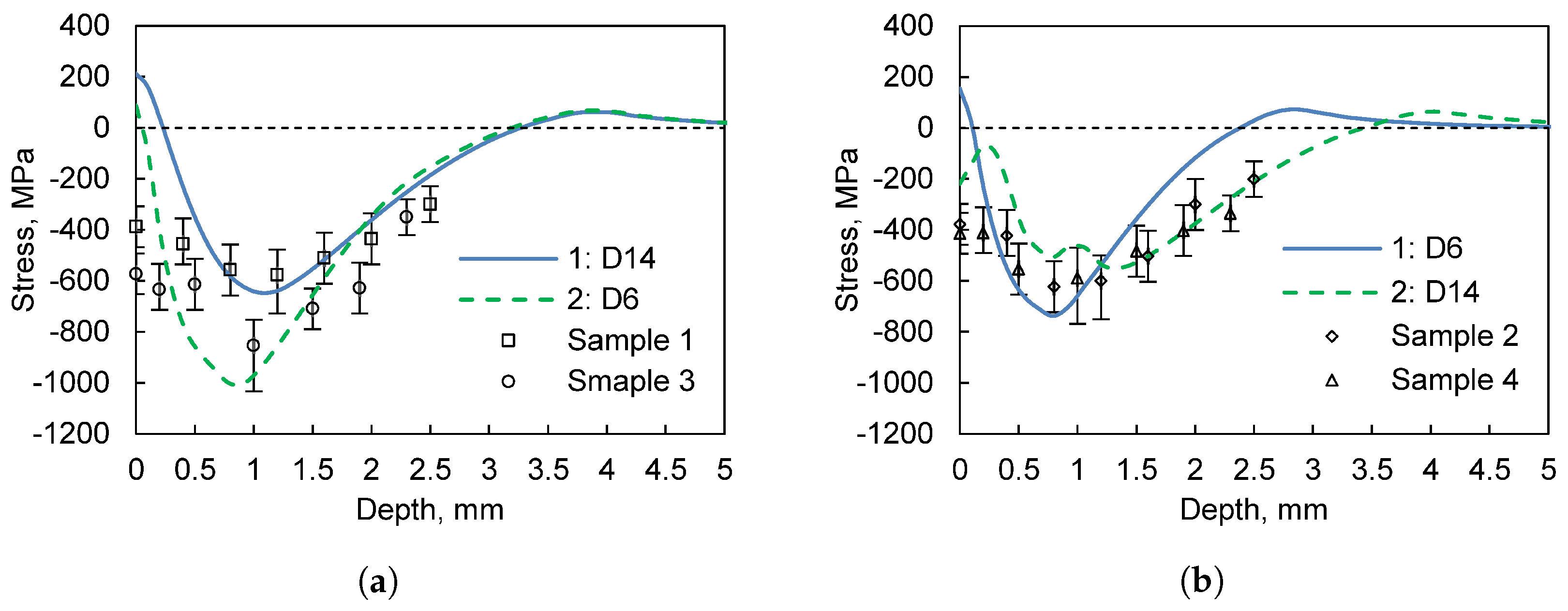
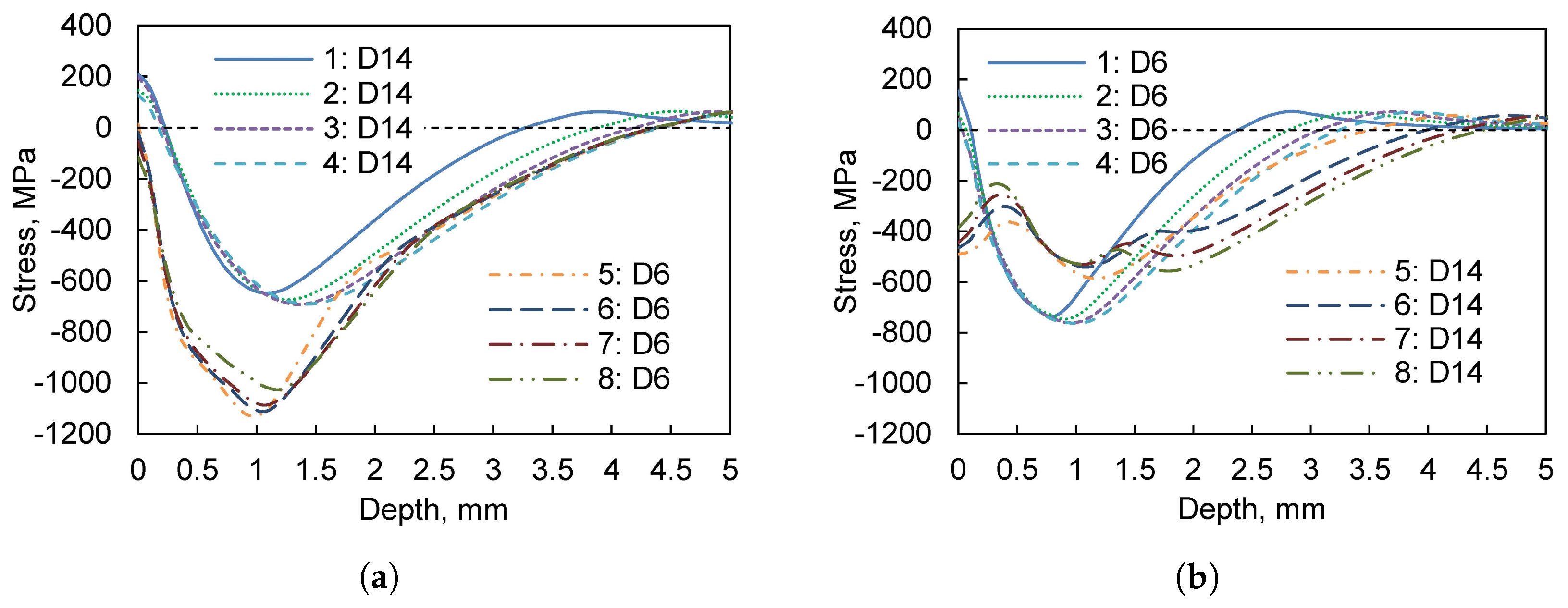
  • The dislocation gradient and slip density of combined hammering specimen are smoother as compared to the specimen treated by single hammering. Big+Small tool head impact sequences have a significant effect on the plastic deformation depth and its strain amplitude, the influence of repeated hammering at the same position diminishes as the number of times increases. Big+Small hammering method can produce the largest residual stress (1000 MPa), it is much bigger than Small+Big method (750 MPa), but the latter is able to form the greater surface compressive stress with deeper field depth and improved uniformity.
  • The variable scale evolution of the shot peening functional field makes predicting the results, controlling the peening process and its macro-micro characterization more difficult, but it also provides new possibilities for further increasing peen formation capability and strengthening effects. It is believed that by controlling the shot media specification, the depth of the plastic deformation zone, and the density of peening, the target part configuration, low surface roughness, smooth gradient organization, and uniform residual stress field can all be obtained simultaneously.
  • The hammer processing device was built based on the electric pick. The radius of the hammer tool head can be much larger than the size of the converntional shot, and the impact kinetic energy of the hammer tool can be regulated over a wide range to control the depth of elastic and plastic deformation of the target, compensates for the size limitations of the large shot used in the conventional shot peening equipment and the consequent lack of driving force.
  • The combined hammering can be used in combination with other strengthening processes such as laser shock peening or water jet peening. The related functional field can be researched in the future.

Author Contributions

All the authors designed research, performed research, analyzed data, and wrote the paper. All authors have read and agreed to the published version of the manuscript.

Funding

This work was funded by National Natural Science Foundation of China (51805432), and China Postdoctoral Science Foundation (2018M633541).

Institutional Review Board Statement

Not applicable.

Informed Consent Statement

Not applicable.

Data Availability Statement

The raw/processed data required to reproduce these findings are available from the corresponding author on request.

Conflicts of Interest

The authors declare no conflict of interest.

References

  1. Festas, A.; Ramos, A.; Davim, J.P. Machining of titanium alloys for medical application-a review. Proc. Inst. Mech. Eng. Part B J. Eng. Manuf. 2022, 236, 309–318. [Google Scholar] [CrossRef]
  2. Yang, R.; Ma, Y.; Lei, J.; Hu, Q.; Huang, S. Toughening High Strength Titanium Alloys Through Fine Tuning Phase Composition and Refining Microstructure. Acta Metall Sin 2021, 57, 1455–1470. [Google Scholar]
  3. Radhika, N.; Sasikumar, J.; Arulmozhivarman, J. Tribo-mechanical behaviour of Ti-based particulate reinforced as-cast and heat treated A359 composites. Silicon 2020, 12, 2769–2782. [Google Scholar] [CrossRef]
  4. Moganapriya, C.; Rajasekar, R.; Ponappa, K.; Karthick, R.; Perundurai, R.V.; Kumar, P.S.; Pal, S.K. Tribomechanical behavior of TiCN/TiAlN/WC-C multilayer film on cutting tool inserts for machining. Mater. Test. 2017, 59, 703–707. [Google Scholar] [CrossRef]
  5. Kheradmandfard, M.; Kashani-Bozorg, S.F.; Lee, J.S.; Kim, C.L.; Hanzaki, A.Z.; Pyun, Y.S.; Cho, S.W.; Amanov, A.; Kim, D.E. Significant improvement in cell adhesion and wear resistance of biomedical β-type titanium alloy through ultrasonic nanocrystal surface modification. J. Alloys Compd. 2018, 762, 941–949. [Google Scholar] [CrossRef]
  6. Huang, J.; Zhang, K.M.; Jia, Y.F.; Zhang, C.C.; Zhang, X.C.; Ma, X.F.; Tu, S.T. Effect of thermal annealing on the microstructure, mechanical properties and residual stress relaxation of pure titanium after deep rolling treatment. J. Mater. Sci. Technol. 2019, 35, 409–417. [Google Scholar] [CrossRef]
  7. Gao, Y. Influence of different surface modification treatments on surface integrity and fatigue performance of TC4 titanium alloy. Acta Metall Sin 2016, 52, 915–923. [Google Scholar]
  8. Chen, J.S.; Desai, D.A.; Heyns, S.P.; Pietra, F. Literature review of numerical simulation and optimisation of the shot peening process. Adv. Mech. Eng. 2019, 11, 1687814018818277. [Google Scholar] [CrossRef]
  9. Yocom, C.J.; Zhang, X.; Liao, Y. Research and development status of laser peen forming: A review. Opt. Laser Technol. 2018, 108, 32–45. [Google Scholar] [CrossRef]
  10. Ohta, T.; Sato, Y. Numerical analysis of peen forming for high-strength aluminum alloy plates. Mater. Trans. 2021, 62, 846–855. [Google Scholar] [CrossRef]
  11. Bagherifard, S.; Hickey, D.J.; Fintová, S.; Pastorek, F.; Fernandez-Pariente, I.; Bandini, M.; Webster, T.J.; Guagliano, M. Effects of nanofeatures induced by severe shot peening (SSP) on mechanical, corrosion and cytocompatibility properties of magnesium alloy AZ31. Acta Biomater. 2018, 66, 93–108. [Google Scholar] [CrossRef] [PubMed] [Green Version]
  12. Huang, Z.; Lu, S.; Xie, C.; Lu, N. Development on surface modification technology of advanced shot peening. Mater. Sci. Technol. 2015, 3, 57–61. [Google Scholar]
  13. Cao, Z.; Zhang, J.; Che, Z.; Zou, S. Residual Stresses of Compound Strengthening Case on TC17 Titanium Alloy by Laser Peening and Shot Peening. Surf. Technol. 2018, 47, 80–84. [Google Scholar]
  14. Wu, J.; Zou, S.; Zhang, Y.; Gong, S.; Sun, G.; Ni, Z.; Cao, Z.; Che, Z.; Feng, A. Microstructures and mechanical properties of β forging Ti17 alloy under combined laser shock processing and shot peening. Surf. Coatings Technol. 2017, 328, 283–291. [Google Scholar] [CrossRef]
  15. Wang, L.; Zhou, L.; Liu, L.; He, W.; Pan, X.; Nie, X.; Luo, S. Fatigue strength improvement in Ti-6Al-4V subjected to foreign object damage by combined treatment of laser shock peening and shot peening. Int. J. Fatigue 2022, 155, 106581. [Google Scholar] [CrossRef]
  16. Li, K.; Zhu, W.; Song, Y.; Li, C.; Liu, S.; Liao, Y.; Jiang, C. Effects of Composite Shot Peening on Surface Microstructure and Properties of OCr16Ni5Mol Martensitic Stainless Steel. Ptca (Part A Phys. Test.) 2022, 57, 32–37. [Google Scholar]
  17. Ongtrakulkij, G.; Khantachawana, A.; Kajornchaiyakul, J.; Kondoh, K. Effects of the secondary shot in the double shot peening process on the residual compressive stress distribution of Ti–6Al–4V. Heliyon 2022, 8, e08758. [Google Scholar] [CrossRef]
  18. Peng, J.; Zhou, C.; Dai, Q.; He, X.; Tang, Z. Strain Rate Sensitivity of Commercially Pure Titanium TA2 at Room Temperature and Revising of Hollomon Empirical Formula [J]. Rare Met. Mater. Eng. 2013, 42, 483–487. [Google Scholar]
  19. He, Q.; Wu, G.; Liu, C.; Liu, J.; Yang, X.K.; Zhou, K.; Zhang, L.W.; Xiang, Y.L. Research Progress on Gradient Nanostructured Metals Prepared by Surface Nanocrystallization Technique. Surf. Technol. 2021, 50, 267–276. [Google Scholar]
  20. Wen, A.; Wang, S.; Yang, Y.; Ren, R. Improvement of Fatigue Performance for Commercial Pure Titanium by Combined High-Energy Shot Peening. Mater. Mech. Eng. 2010, 34, 55–57. [Google Scholar]
  21. Xiao, X.; Sun, Y.; Yang, Z.; Yang, M.; Li, Y.; Gao, G. Dynamic response of target with different peening media. Surf. Eng. 2020, 36, 386–396. [Google Scholar] [CrossRef]
  22. Xiao, X.; Tong, X.; Sun, Y.; Li, Y.; Wei, S.; Gao, G. An analytical model for predicting peening stresses with general peening coverage. J. Manuf. Process. 2019, 45, 242–254. [Google Scholar] [CrossRef]
  23. Zhang, C.; Zheng, M.; Wang, Y.; Gao, P.; Gan, B. Effect of high energy shot peening on the wear resistance of TiN films on a TA2 surface. Surf. Coat. Technol. 2019, 378, 124821. [Google Scholar] [CrossRef]
Figure 1. Microstructure on TA2 plate surface (a) before and (b) after annealing treatment.
Coatings 12 01974 g001
Figure 2. (a) Device of combined hammering (D6-head diameter of punch tool is 6 mm, D14 is 14 mm, Ra0.8), (b) the sliding table on the right side control the impact position.
Coatings 12 01974 g002
Figure 3. (a) Type V, (b) Type A finite element model of combined hammer peening and (c) D6-D14 mesh size.
Coatings 12 01974 g003
Figure 4. Contact relations between hammering tool and original dimple.
Coatings 12 01974 g004
Figure 5. (a) Dimple radius and (b) difference between indenting depth of hammering tool and original dimple depth.
Coatings 12 01974 g005
Figure 6. (a) Gap between tool tip and dimple apex at bottom point of hammering and (b) residual dimple depth.
Coatings 12 01974 g006
Figure 7. Surface morphology of hammering treated (a) sample 1, (b) sample 2, (c) sample 3 and (d) sample 4.
Coatings 12 01974 g007
Figure 8. Microstructure near surface of hammering treated (a) sample 1, (b) sample 2, (c) sample 3 and (d) sample 4.
Coatings 12 01974 g008
Figure 9. Equivalent plastic strain (PEEQ) combined hammering.
Coatings 12 01974 g009
Figure 10. Evolution of equivalent plastic strain (PEEQ) of combined hammering.
Coatings 12 01974 g010
Figure 11. Raplaced volume by hammering tool.
Coatings 12 01974 g011
Figure 12. Stress field of combined hammering simulation and measured values on samples.
Coatings 12 01974 g012
Figure 13. Stress evolution of combined hammering simulation.
Coatings 12 01974 g013
Table 1. Chemical composition in wt (%) of TA2.
FeCOHNTi
0.0650.020.110.00020.014Bal.
Manufacturer: Baoji Titanium Industry Co., China.
Table 2. Experimental parameters.
SampleFirst PeeningSecond Peening
D tool /mm f p /Hz n c /mm 2 D tool /mm f p /Hz n c /mm 2
114284.014284.0
26203.76203.7
314284.06203.9
46204.014284.2
Note: D tool —head diameter of punch tool, f p —hammering frequency per second, n c impact times per unit area.
Table 3. Parameter of finite element simulation.
SampleFirst PeeningSecond Peening
D tool /mm M tool /g V tool /mm/sNumber D tool /mm M tool /g V tool /mm/sRepetitions r i
Type V6420.78/411911/2/3/414405.66/417681/2/3/4
Type A14405.66/417681/2/3/46420.78/411911/2/3/4
Note: D tool —head diameter of punch tool, M tool —mass assigned to the finite element model of tool, V tool —velocity of tool.
Publisher’s Note: MDPI stays neutral with regard to jurisdictional claims in published maps and institutional affiliations.

