Article

Effect of Temperature and Al2O3 NanoFiller on the Stress Field of CFRP/Al Adhesively Bonded Single-Lap Joints

1
Computational Mechanics Group, Department of Mechanical Engineering, School of Mechanical and Manufacturing Engineering (SMME), National University of Sciences and Technology (NUST), H-12, Islamabad 44000, Pakistan
2
Department of Mechanical Engineering, Capital University of Science and Technology (CUST), Islamabad 44000, Pakistan
3
Department of Intelligent Mechatronics Engineering, Sejong University, Seoul 05006, Republic of Korea
4
Department of Unmanned Vehicle Engineering, Sejong University, Seoul 05006, Republic of Korea
5
Department of Intelligent Mechatronics Engineering and Convergence Engineering for Intelligent Drone, Sejong University, Seoul 05006, Republic of Korea
6
Department of Semiconductor Systems Engineering, Sejong University, Seoul 05006, Republic of Korea
*
Authors to whom correspondence should be addressed.
Coatings 2022, 12(12), 1865; https://doi.org/10.3390/coatings12121865
Submission received: 15 October 2022 / Revised: 28 November 2022 / Accepted: 29 November 2022 / Published: 30 November 2022

Abstract

:
In this paper, the effect of aluminum oxide, Al2O3, nanoparticles’ inclusion into Epocast 50-Al/946 epoxy adhesive at different temperatures, subjected to quasi-static tensile loading, is numerically investigated. The single-lap adhesive joint with two different types of material adherends (composite fiber-reinforced polymer (CFRP) and aluminum (Al) 5083 adherends) and adhesive Epocast 50-A1/hardener 946 were modeled in ABAQUS/CAE. A numerical methodology was proposed to analyze the effect on peel stress and shear stress by adding Al2O3 nanoparticles into the neat adhesive at 25 °C, 50 °C, and 75 °C temperatures at four different locations of the adhesive regions: the interface of the adhesive and aluminum adherend (location A), the middle plane of the adhesive region (location B), the middle longer edge (along the length of the adhesive, location C), and the middle shorter edge (along the width of the adhesive, location D). The results showed that adding nanoparticles into the neat adhesive improves joint strength at room and elevated temperatures. High peel and shear stresses were recorded near both edges of the locations (A, B, C, and D). For location A, adding nanofillers into the adhesive resulted in the reduction in peak peel stress by 1.3% for 25 °C; however, it increased by 2.7% and 10.7% for 50 °C and 75 °C temperatures, respectively. Furthermore, the peak shear stress observed a considerable reduction of 19.6% for 25 °C, but it increased by 7.7% and 8.7% for 50 °C and 75 °C temperatures, respectively, for location A. The same trend was also observed for other locations (i.e., B, C, and D). This signified that adding aluminum oxide nanoparticles in the adhesive resulted in increased stiffness at higher temperatures and increased ductility of the joint, as compared to the joint with neat adhesives at room temperature. Moreover, it was observed that locations A and B were more vulnerable to damage initiation, as the peak of stresses lay near the edges, indicating that the crack initiation would take place close to the edges and propagate towards the center, leading to ultimate failure.

1. Introduction

The use of adhesive joints as a primary choice for connecting different components has gained popularity for objective and subjective reasons [1]. In adhesive joints, the most important part is the adhesive itself, which acts as a bonding agent to join similar or different parts. Various types of adhesives are available, with subtle and significant differences, having various applications. These applications include computers, auto parts, the aerospace industry, mobile phones, medical devices, the marine industry, the construction industry, etc. [2]. Adhesive joints, compared to conventional mechanical joints, have several superior characteristics, including low weight, high stiffness, high strength, and very low cost [3,4,5,6,7,8]. In addition to these advantages, adhesive joints also have various advantages in structural applications. In conventional mechanical joints, holes are drilled in the material, which is a crack-initiating process. After applying load, the cracks may propagate, which leads to failure. Various types of adhesive joints are used in structural applications, including single- and double-lap joints, plain butt joints, single- and double-strap joints, joggle lap joints, etc. [8].
Single-lap joints (SLJs), manufactured by bonding the metal adherends and adhesive on top of one another, having some overlap area, are widely used in repairing structures, such as bridges, aircraft, turbine blades, windmills, etc. [8]. In these types of joints, shear and peel stresses occur when the adherend metal pulls away. As the single-lap joints are eccentric, they tend to obtain peak peel stresses at the end of overlap regions. The stress concentration is higher at the end of overlap regions, whereas lower stress occurs at the center overlap region [9,10].
The literature review regarding these types of adhesive joints identified that SLJs can be used in various combinations. For example, joints with the same material adherends, joints with different material adherends, such as carbon fiber-reinforced polymer, or CFRP, and aluminum, and joints using nanoparticles in adhesives with different material adherends, etc. Researchers have performed various studies on the adhesive joints by varying the composite strap shape, geometry of the edge, the type of fiber, layup sequence, length of the overlap region, the thickness of the adhesive, and temperature. Kimiyoshi Naito [11] investigated the adhesive thickness effect on shear strength and tensile strength. The test was carried out on a single-lap and butt joint. The adhesive and adherend used were polyimide (Skybond 703) and aluminum (5052-H34), respectively. The results showed that as adhesive thickness was increased, tensile strength decreased, but shear strength was unaffected. The failure was of an interfacial manner, whatever the thickness of the adhesive was. According to FEM linear elastic stress analysis, there was a concentration of normal stress between the adhesive and adherend. Conducting FEM analysis considering stress at interfaces adds to the understanding of the effect of the thickness of the adhesive on the strength of the joint. Lucas da Silva [12] investigated the strength of adhesive joints incorporating a mixed adhesive. An SLJ was manufactured and used to test the configuration of brittle material adhesive in the middle area and three different types of ductile material adhesive at both ends. In line with the author’s prediction of the strength of the joint, it was observed that using mixed adhesive material joints showed more improvement in strength than using brittle material adhesive in the joint. Araújo and Machado [13] studied the strength of composite adhesive joints with different material adherends under impact loading. It was concluded that such types of adhesives and combining two dissimilar adherends, particularly CFRP, exhibit exceptional damping capabilities and impact strength. Banea and Rosioara [14] analyzed three configurations of (multi-material) composite adhesive joints experimentally and numerically. The materials that were used to form the adhesive joints were hard steel (HS), aluminum (Al), and CFRP, i.e., CFRP/Al and CFRP/HS. Factors such as the stiffness of adherends and the overlap length, affecting the strength of the composite adhesive joints, were analyzed. The results showed that the material and/or geometry combination effect was not significant on the strength of the joints, whereas failure in the SLJs having relatively small overlap lengths was dominated by the global yielding of the adhesive. Similarly, Reis and Ferreira [15] conducted a comparative study on the shear strength of SLJs with different material adherends. Composite, steel, and aluminum adherends were combined in different combinations. Adherend stiffness was the primary factor influencing the shear strength of the joints. Depending on the material of adherends, the overlap length of the adhesive joints also affected the shear strength. Jairaja and Narayana [16] investigated dual adhesives in SLJs of different adherends. It was known that the strength of an adhesive joint depends on the adhesive type and its properties. This has more importance in composite adhesive joints, such as those with CFRP and aluminum, which were under study by them. They used two adhesives, Araldite 2015 and AV138, separately and in combination. In combination, the adhesive that has ductile properties must be at the ends, whereas brittle adhesive must be in the middle; that is what they did. According to their results, using two adhesives in combination helped in gaining higher strength for the composite adhesive joints. Joints having carbon-reinforced polymer plastic and aluminum as adherends were analyzed in great numbers, with different adhesives depending on the application [17,18].
The effects of temperature on the performance of adhesive joints have also been a prime focus of the literature. Rahmani and Choupani [19] investigated the aluminum–aluminum adhesive joints at different low temperatures for fracture parameters. The results showed that yielding strength, ultimate strength, and Young’s modulus increased at low temperatures. It was observed that the rates of critical strain energy and intensity of stress factors increased by reducing the temperature. Adamvalli [20] determined the dynamic strength of a single-lap joint adhesive. The analysis was performed at different temperatures, 25 °C to 100 °C, and at varying loading rates. The study’s findings demonstrated that strength considerably decreased at high temperatures, although the opposite was true for the loading rate. The effect of temperature on the strength of the joint was seen to be significant. From the literature, it was observed that increasing the temperature causes the strength of the joint and elastic modulus to decline [21,22,23].
The epoxy adhesive properties, such as mechanical strength, can be enhanced by including nanoparticles [24,25,26,27,28,29]. Scarselli and Corcione [30] investigated single-lap joints that were manufactured, tested, and simulated. Two types of adhesives were used: one was a conventional adhesive, i.e., joined with epoxy resin, and the other was a combination of epoxy resin and nano-graphite particles. Their research showed superior mechanical properties when nano-graphite was added to epoxy. Khashaba [31] investigated the dynamic analysis of an adhesive joint, in which a CFRP composite was altered with aluminum oxide nanoparticles, Al2O3, under fatigue conditions at various temperatures. The addition of the nanoparticles to the joint resulted in good results, as a 4.8% increase in shear strength of the joint at room temperature and a 24.5% rise at 50 °C were observed. The reduction in the glass transition temperature to 50 °C resulted in a decrease in fatigue strength. Alumina (aluminum oxide, Al2O3) nanoparticles, when added to epoxy at 1.5 wt%, bear good results, as proved by the research studies [32,33].
The literature review concluded that the synergetic effects of an increase in temperature and the addition of aluminum oxide nanoparticles on the joint strength of single-lap joints remained largely unexplored in the previous work. It was also concluded that the researchers mainly focused on investigating the fracture behavior of the interface region in single-lap joints. However, there is a substantial stress concentration on the middle and edge portions, and the investigation of areas with a high stress concentration is compulsory and highly significant [34,35,36]. Therefore, this research involved the development of a methodology to investigate the effects of both increases in temperature and the inclusion of aluminum oxide nanoparticles on the stress behavior at different locations on the adhesive region. Composite single-lap joints (SLJs) of carbon fiber-reinforced polymer, or CFRP, and aluminum were numerically investigated at three different temperatures, which were 25 °C, 50 °C, and 75 °C, to evaluate the peel and shear stress behavior at four locations on the adhesive region, with and without aluminum oxide nanoparticles with a concentration of 1.5 wt% in the adhesive. The joint was subjected to quasi-static tensile loading for each case to determine the effect of nanoparticles at different temperatures in the adhesive on peel and shear stresses at the adhesive region.

2. Methodology

An implicit scheme was employed to execute the simulation of the static loading with the help of the finite element analysis software package ABAQUS/Implicit.

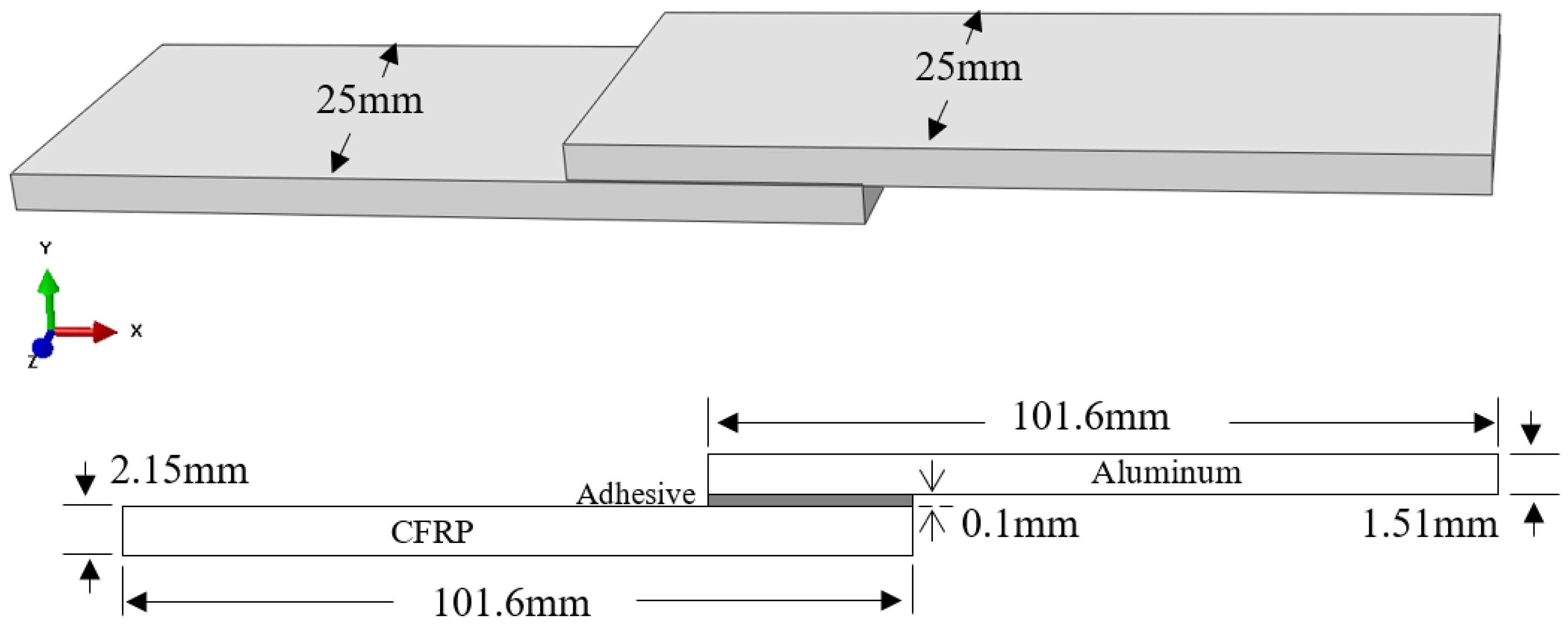
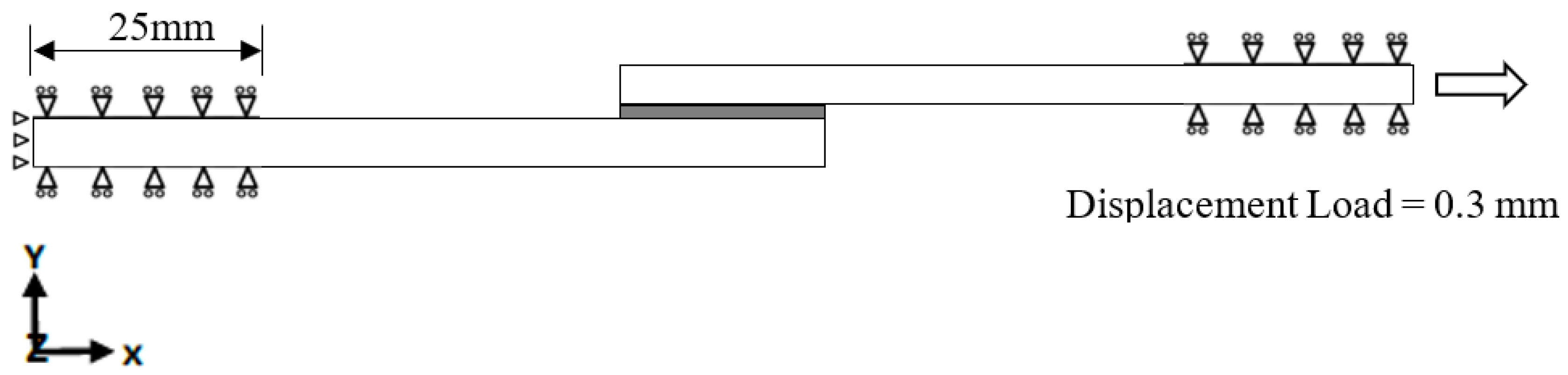
2.1. Models Geometries, Materials Properties, and Boundary Conditions
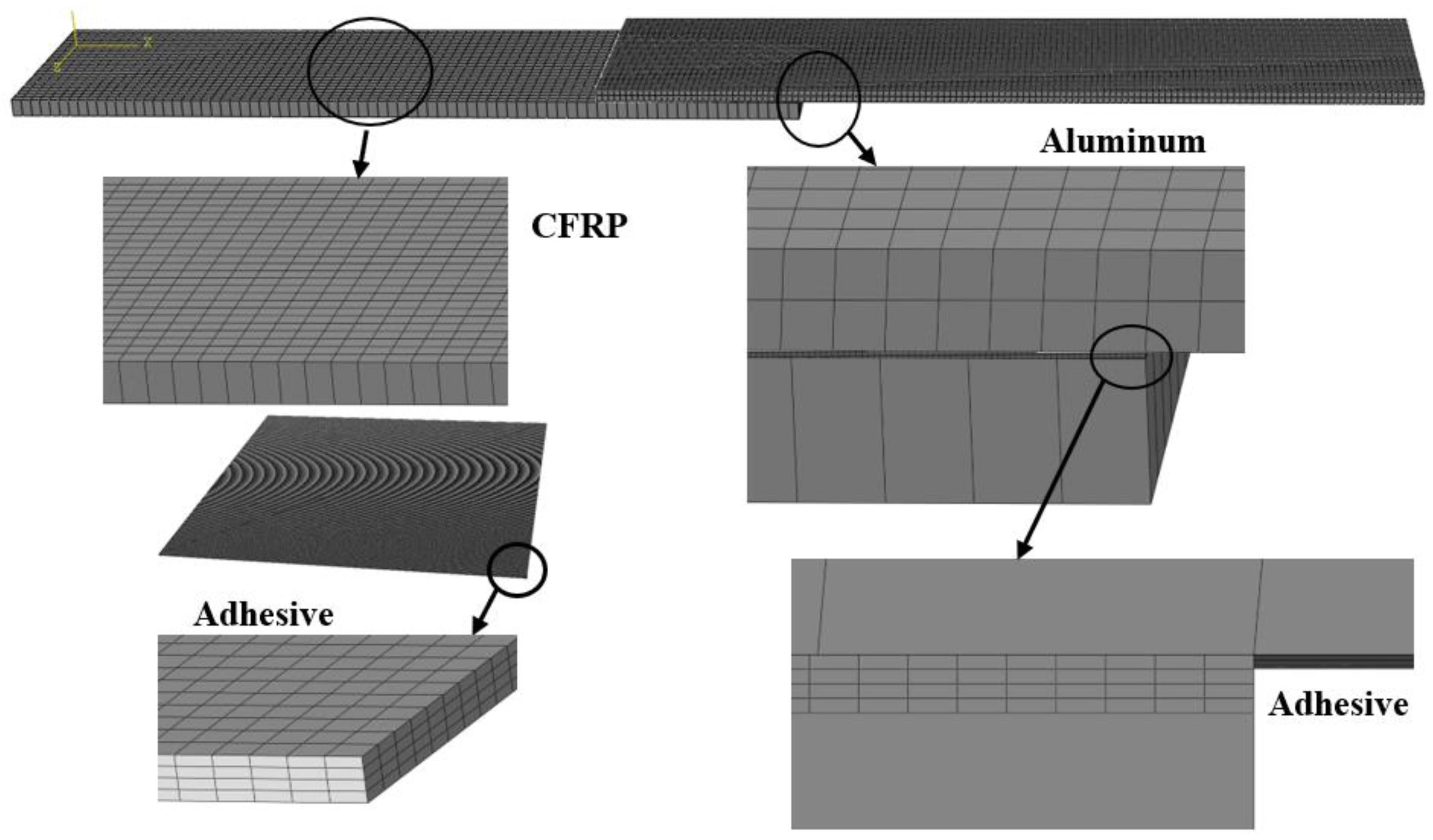
A three-dimensional (3D) single-lap joint made of aluminum 5083 and T300/QY8911 CFRP as adherends, and Epocast 50-Al resin with hardener 946 as the adhesive, was modeled in ABAQUS CAE. The inclusion of aluminum oxide, Al2O3 (alumina), nanoparticles to the adhesive were modeled by assigning material properties to the adhesive. A tie constraint was applied between the adhesive and the adherends. The dimensions of the model of the SLJ are given in Figure 1.
The aluminum adherend was considered a linear isotropic material and modeled with elastic behavior, and the adhesive was modeled with elastic-plastic properties. It was considered that the adhesive was an isotropic material and had non-linear stress–strain data taken from [37]. The plastic properties of the adhesive material were assigned using a stress–strain curve at 25 °C, 50 °C, and 75 °C temperatures given in [37]. The adhesive was modeled with and without 1.5 wt% of alumina nanoparticles. In the study [33], the adhesive was analyzed with 0.5 wt%, 1 wt%, 1.5 wt%, and 2 wt% of alumina and other nanoparticles; however, their results showed that adding 1.5 wt% of alumina nanoparticles into the adhesive provided considerably better mechanical properties. The nanoparticles had a spherical outer diameter of 15 nm with 99.9% purity, manufactured by Timesnano, Chengdu Organic Chemicals Co. Ltd., Chinese Academy of Sciences, as mentioned in [33,37]. Based on the study and selection in [33], the current research chose 1.5% alumina nanoparticles to be added to the adhesive. Moreover, the mixture of epoxy resin and nanoparticles was mechanically stirred using a high-speed homogenizer at 2400 rpm. After mechanical stirring, a high-intensity ultrasonic processor (750 W) was used to achieve the uniform dispersion of nanoparticles in the epoxy [33,37].
The material properties of the adhesive, along with the standard deviations, are given in Table 1. A total number of 75 specimens were tested under tensile loading, using ASTM standards for the different configurations of epoxy and nanoparticles to achieve mechanical properties [37]. On the other hand, the bi-directional [0/90]s composite adherend of T300/QY8911 was modeled with an orthotropic element, with properties given in Table 2 [38].
The single-lap joint was completely fixed at one end, and a displacement boundary condition was applied at the other. A displacement of 0.3 mm was applied for tensile testing. The boundary conditions are shown in Figure 2.

2.2. Mesh Details

Since different mesh elements were needed for the composite adherend, the joint’s parts meshed individually. The aluminum and adhesive were meshed with a linear 8-node brick element with reduced integration (C3D8R from ABAQUS), whereas a quadrilateral continuum shell element (SC8R from ABAQUS) was applied on the composite adherend. The reason for choosing a different element type was that CFRP layers can only be modeled with a solid-shell model. There is a specific family of elements, i.e., a continuum shell, for the meshing of a CFRP adherend. The composite adherend has one element in the thickness direction, whereas the aluminum adherend and adhesive have two and four elements in the same direction, respectively. The global mesh size for CFRP and aluminum adherends is 1 mm. Mesh sensitivity analysis was performed. It was concluded that the final adapted mesh would compromise the time required and output quality. Therefore, as a result of the mesh convergence study, the case with a total number of elements of 371,526 was chosen. The meshing of different parts of the joint is shown in Figure 3.

3. Results and Discussion

Peel and shear stresses were numerically analyzed at four different locations on the adhesive region. The research was divided into two major cases: (1) an SLJ with a neat/pure adhesive, and (2) an SLJ with 1.5 wt% alumina nanoparticles added to the neat/pure adhesive. The SLJs were subjected to 25 °C, 50 °C, and 75 °C temperatures. The prime objective was to discover the effect of nanoparticles on the joint at geometrical locations. The results focused on the stresses in the adhesive layer during tensile loading at four specific locations, shown in Figure 4. These locations were the middle of the interface of the adhesive and Al (at the top face of the adhesive), represented by location A, the middle plane of the adhesive region, represented by location B, the middle shorter edge (along the width of the adhesive), represented by location C, and the middle longer edge (along the length of the adhesive), represented by location D.

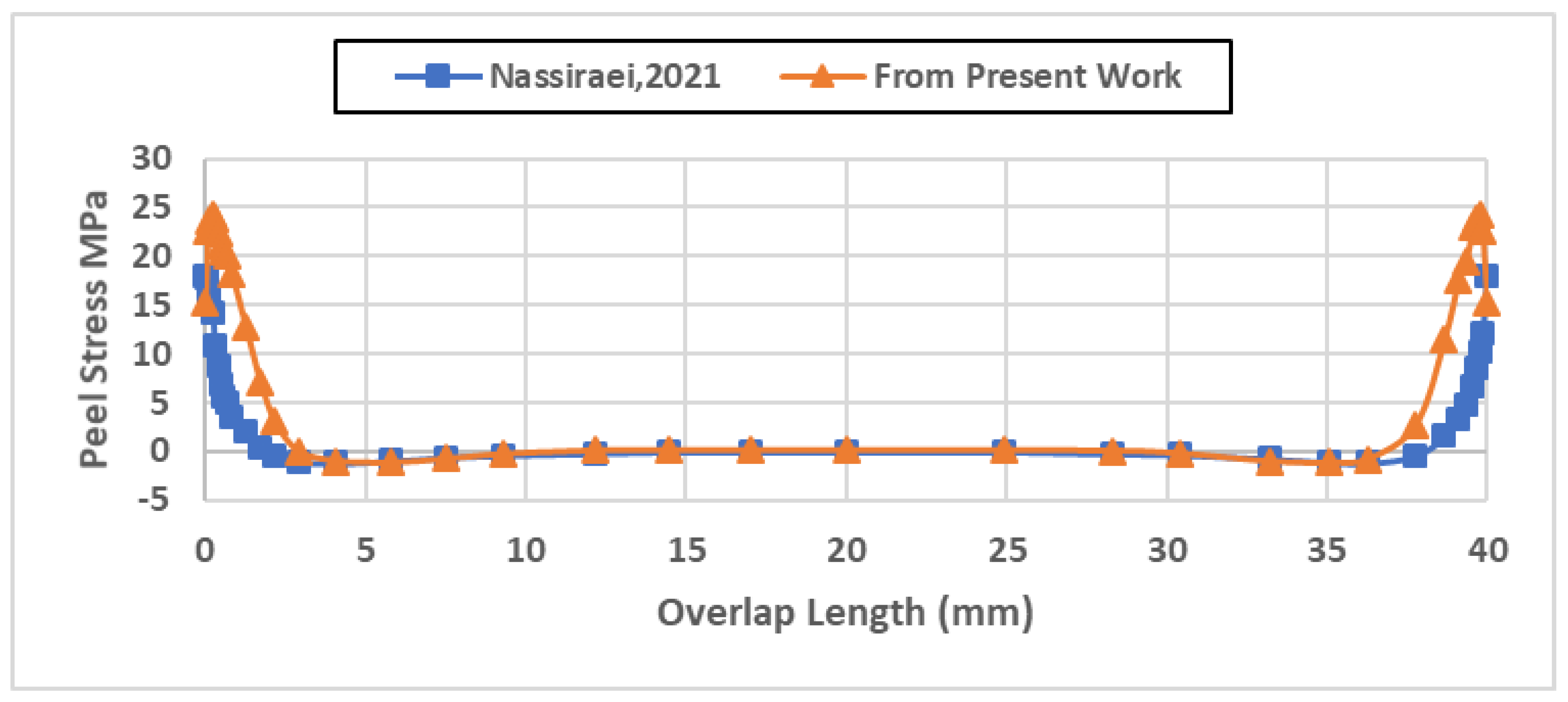
3.1. Model Validation

The present model was validated with the configuration (1) of the literature [36], in which the author compared the results of the numerical model with the experimental results. The variable used in the validation was peel stress generated in the adhesive upon deformation in quasi-static loading. Figure 5 shows the comparison of both numerical models. A good correlation was observed between the results of the numerical model from the referenced work [39] and the proposed model. The significant difference could be seen in the peel stress around the corners of the adhesive region. The possible reason is that the mentioned work used cohesive zone modeling (CZM), which is not used in the present proposed model. As CZM finds its application in numerical simulations of interfacial fracture behaviors, particularly composite delamination and adhesive joint fracture [40], this methodology focuses only on the elastic deformation region of the single-lap joints; therefore, CZM was not applied in this research. Moreover, in this research, the present model was validated with previously referenced work, based on the available data in that research.

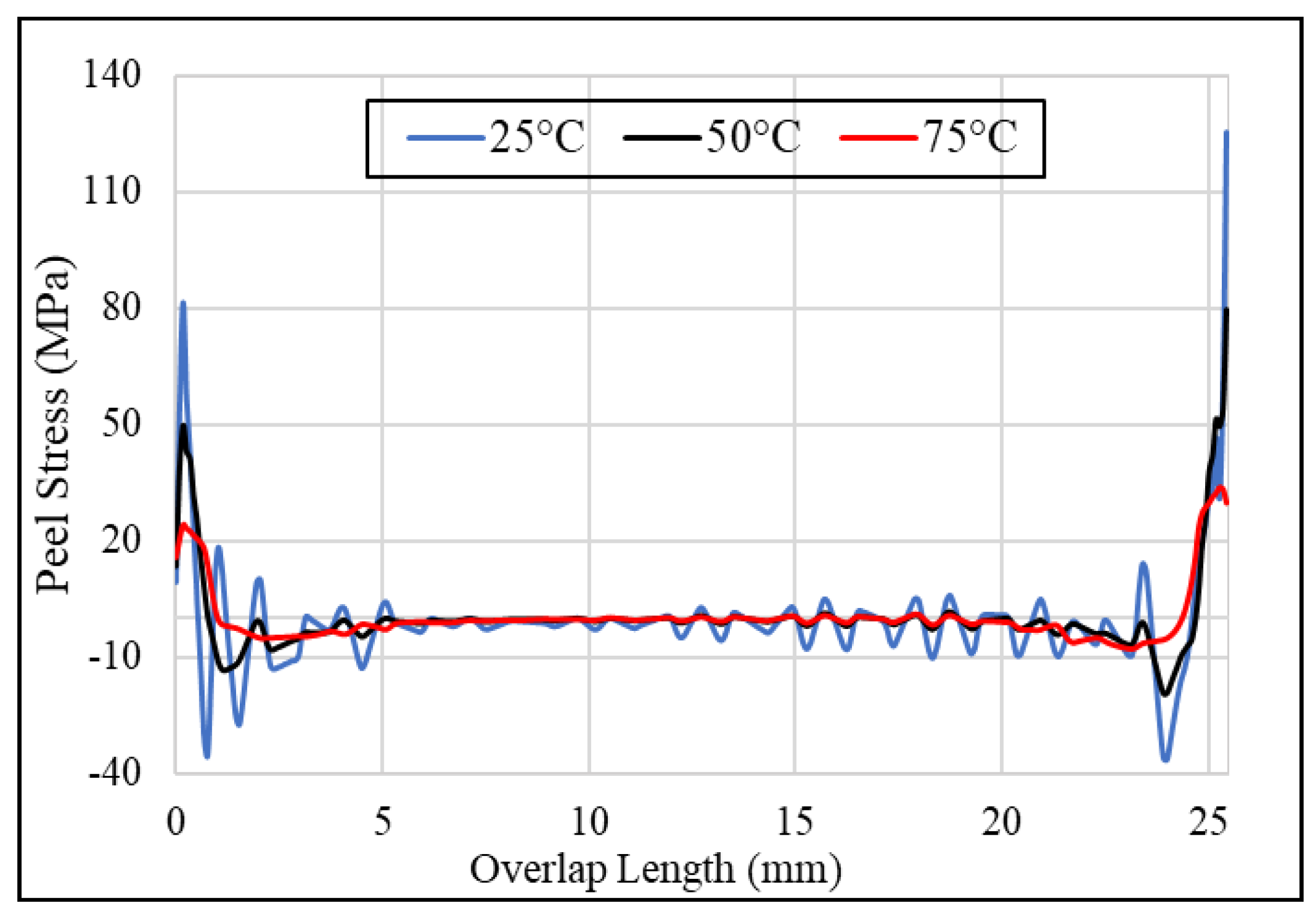
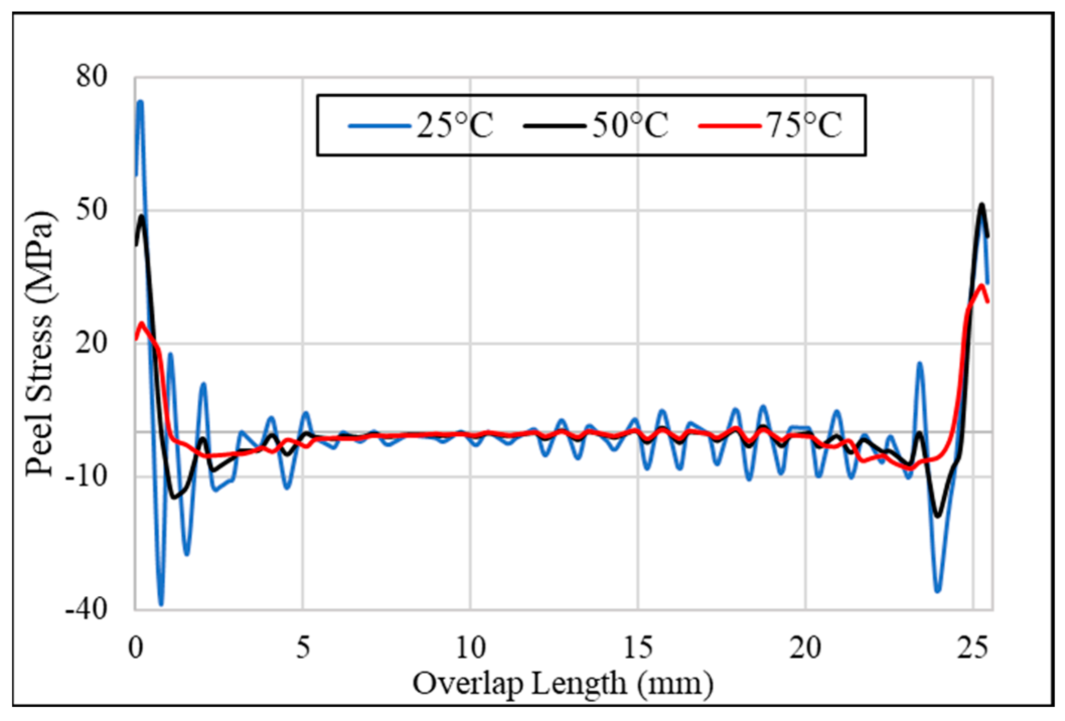
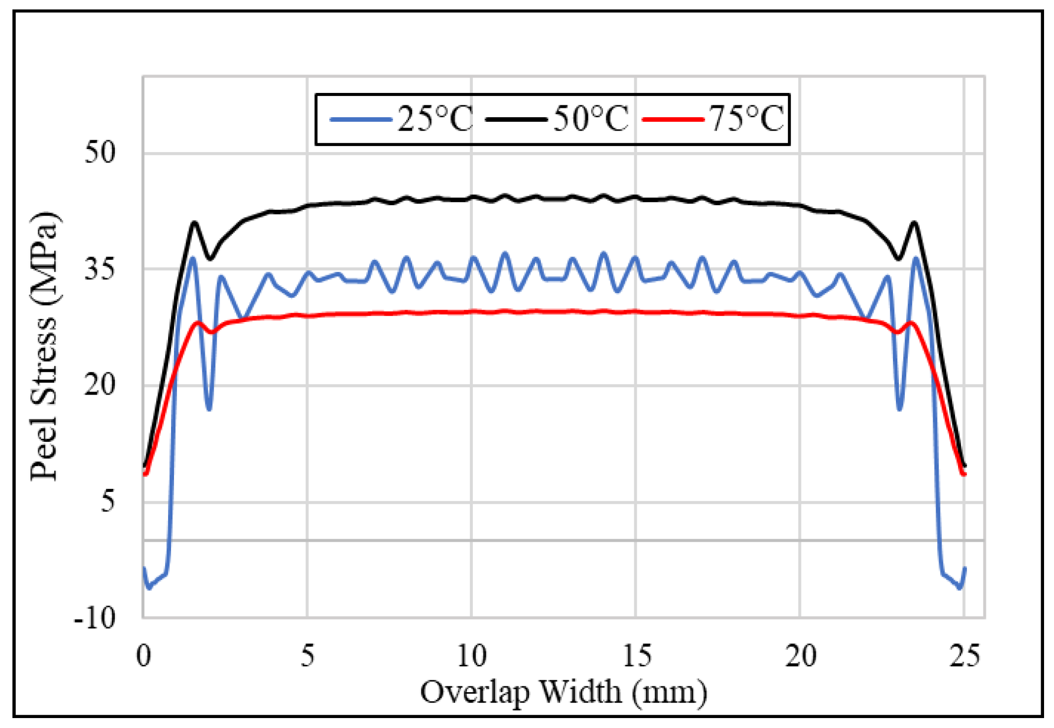
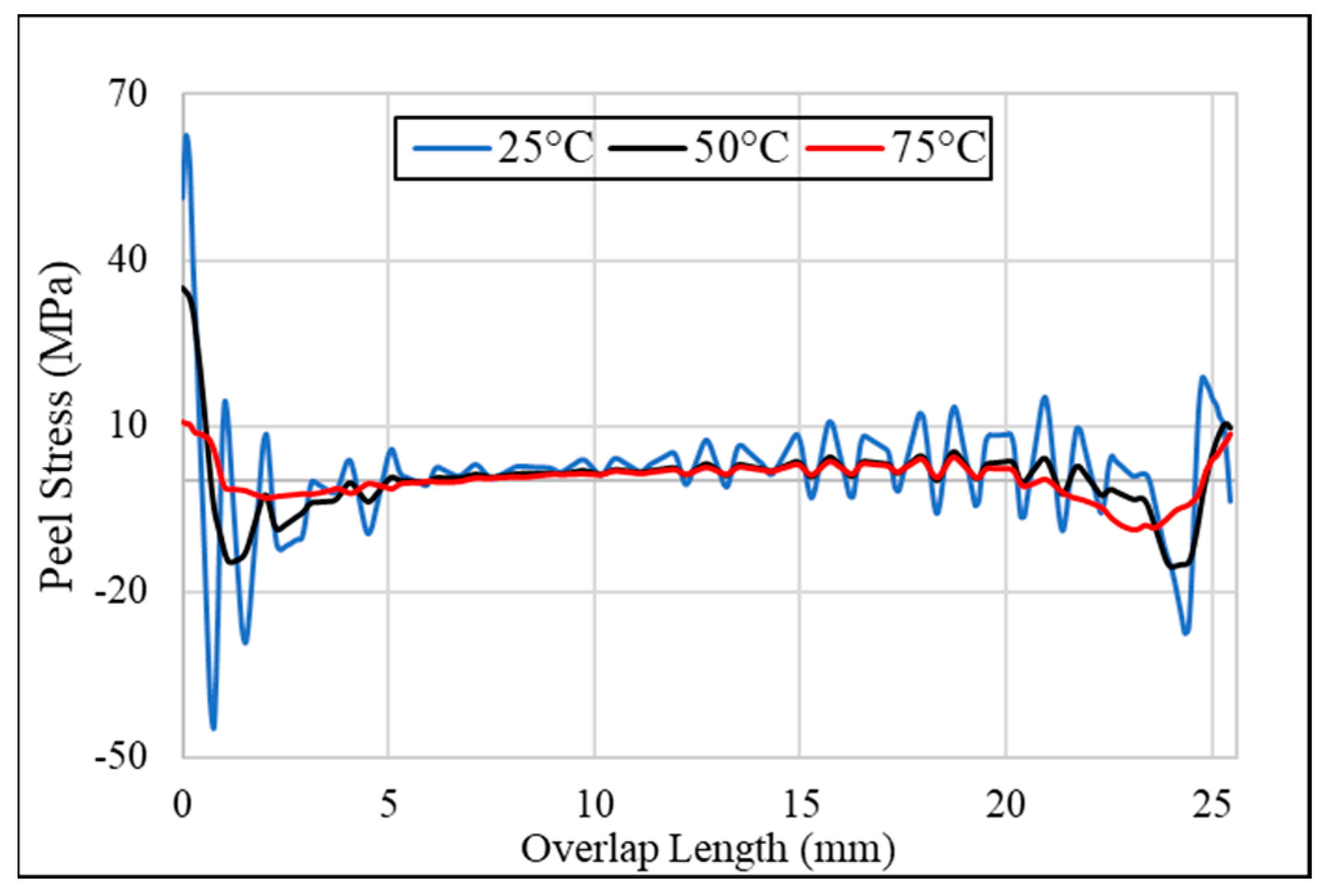
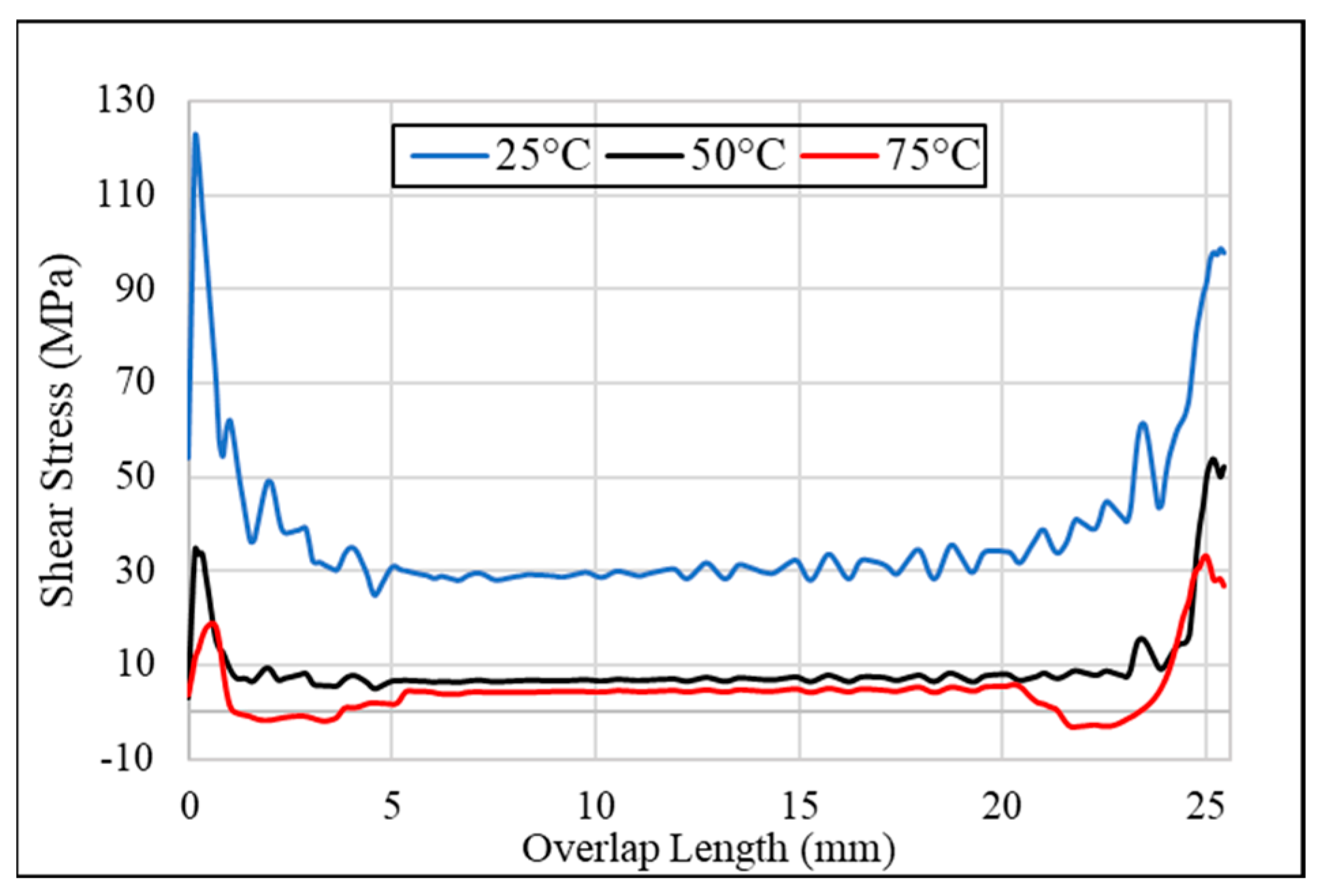
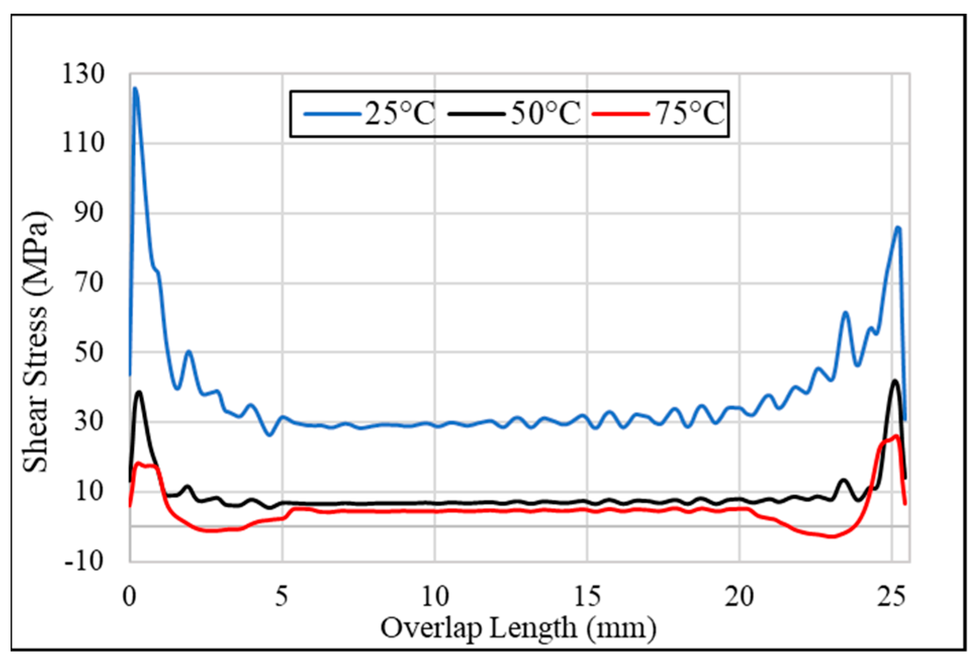
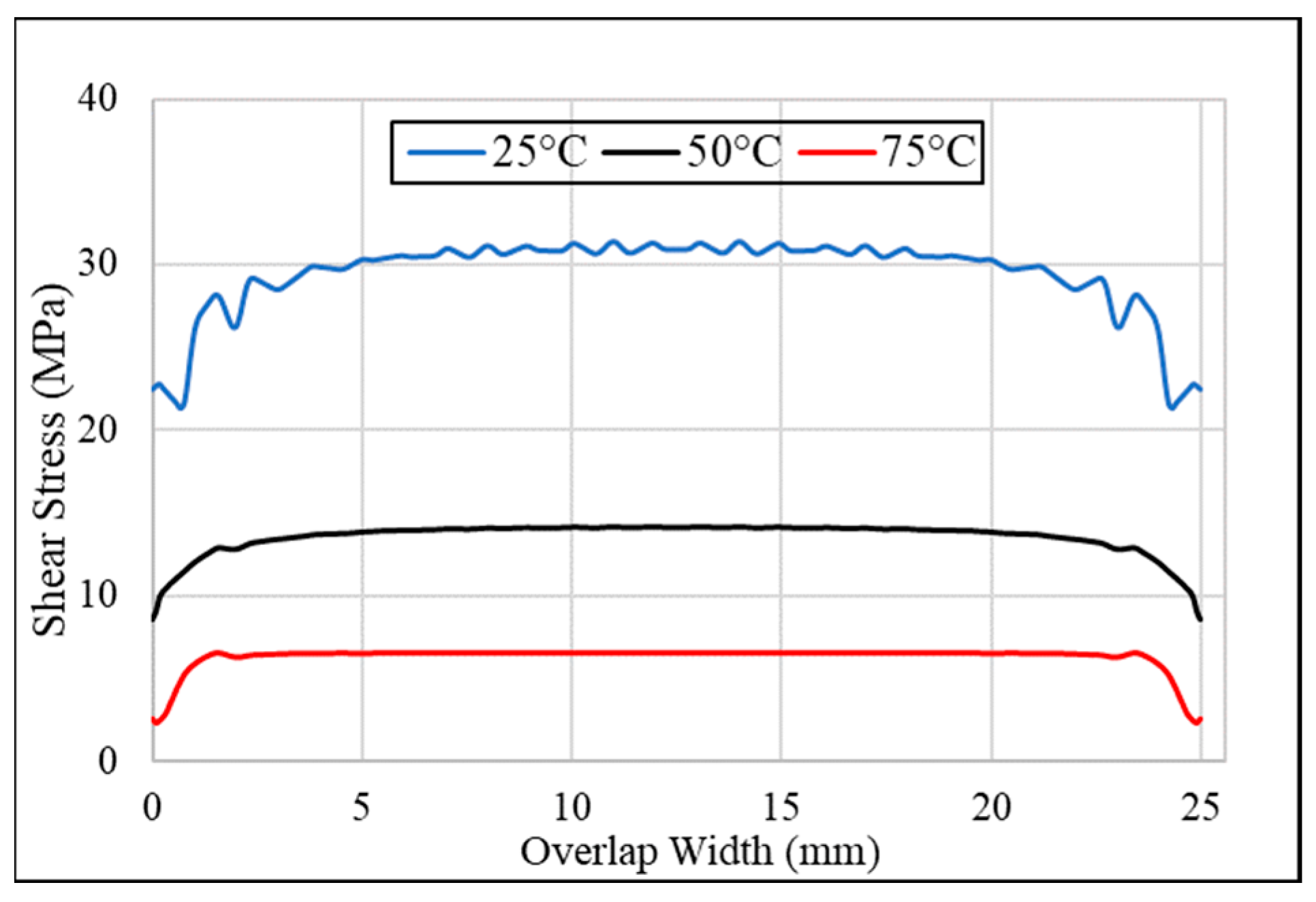
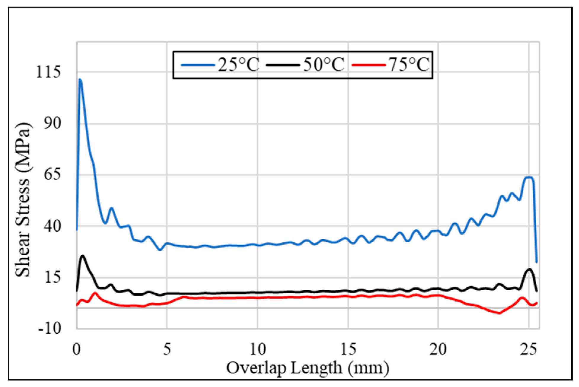
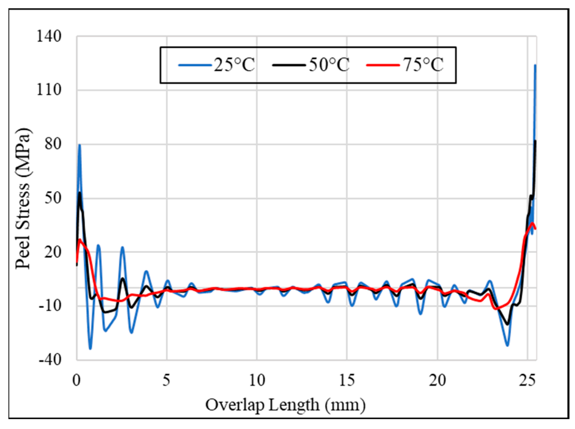
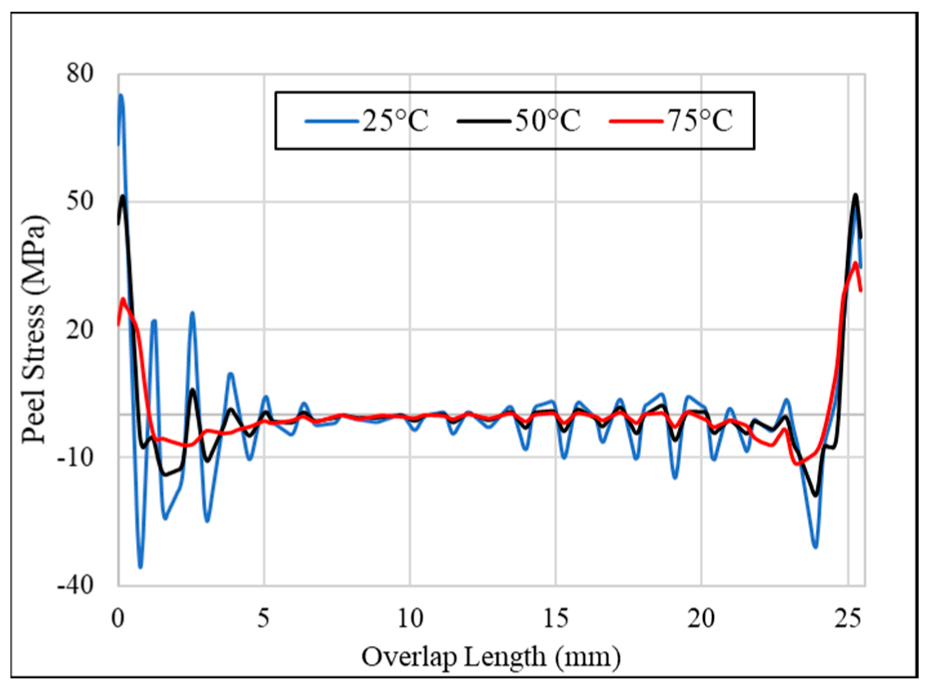
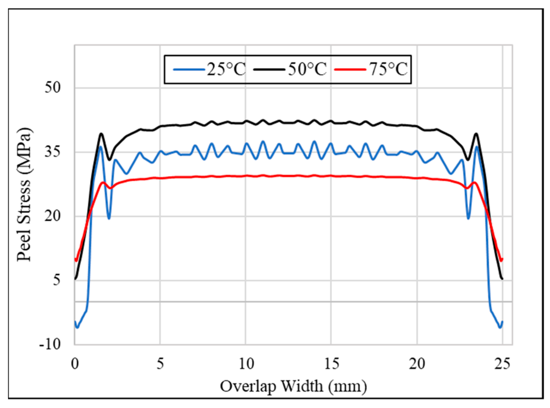
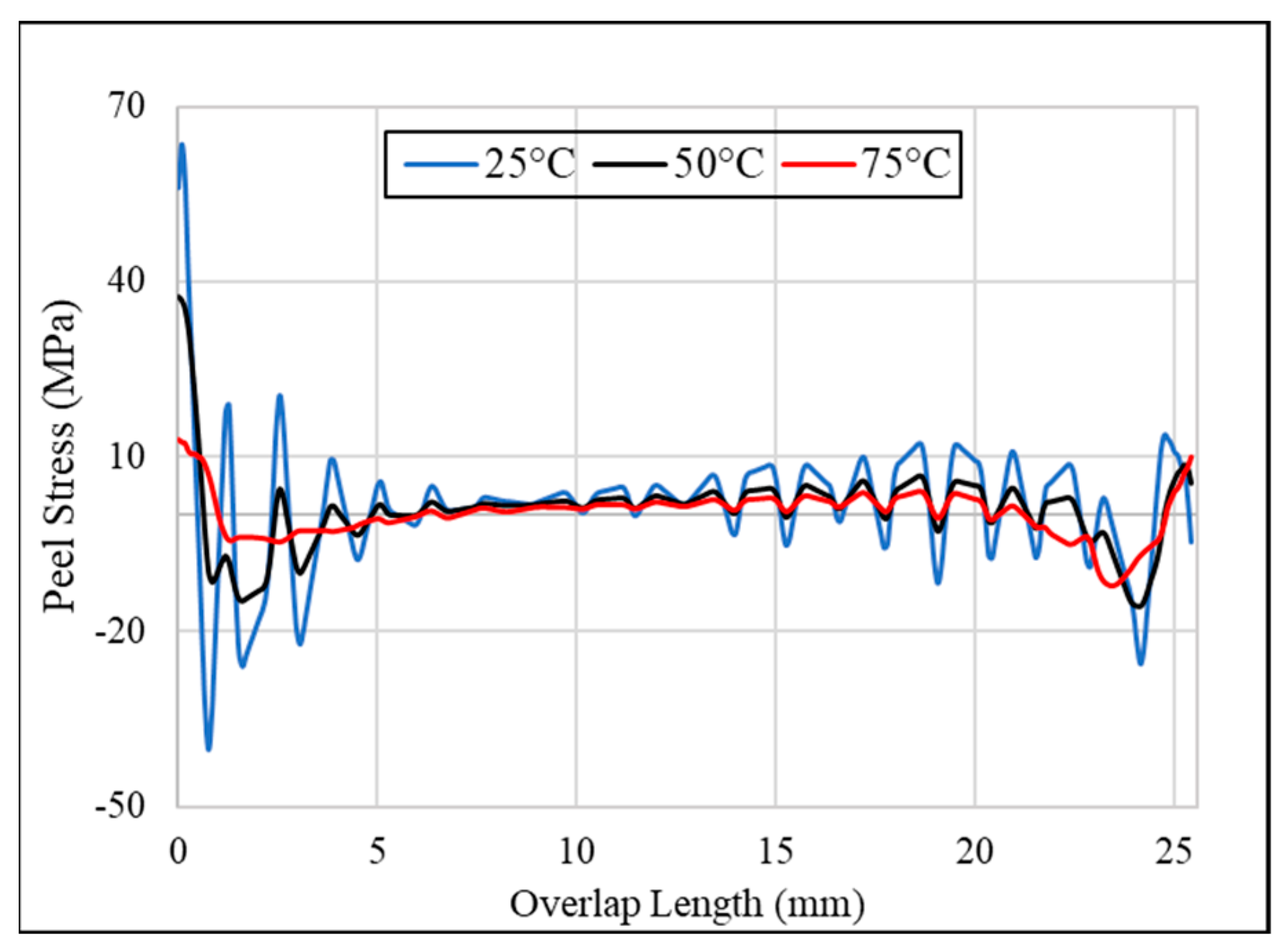
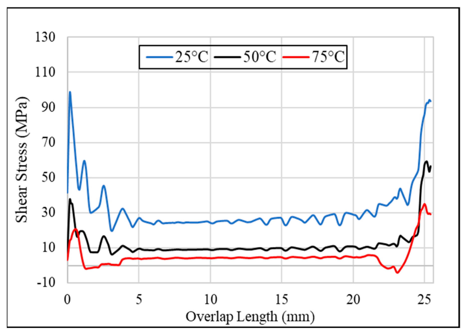
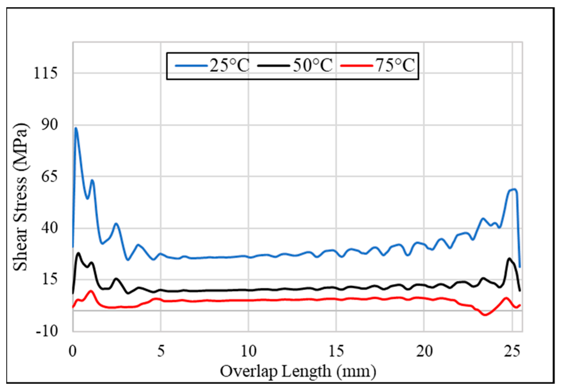
3.2. Effect of Temperature on Peel Stress and Shear Stress of Joint with Pure/Neat Adhesive

This section shows the variation of peel stress and shear stress at different temperatures, i.e., 25 °C, 50 °C, and 75 °C, for the specified locations given in Figure 4. The peel stress variations at different temperatures for locations A, B, C, and D are given in Figure 6, Figure 7, Figure 8 and Figure 9, respectively. Peel stress in a single-lap joint is caused by bending during tensile loading, which is due to the eccentricity of the joint. The peel stress is high around the corners and almost zero in the middle of the adhesive. Peel stress is one of the determining factors of mechanical strength [36]. The research in [39] and other research works [32,38] did obtain the same peel stress variations. So, it is evident that peel stress is high around the edges of the adhesive joint. As the temperature increased, a stress reduction was observed. High temperatures cause the adhesive to become more ductile, making it easier to peel off with little resistance. This low resistance to peel action is shown as a reduction in peel stress. From the research [37], it was observed that with an increase in temperature, the modulus of elasticity and stiffness of the adhesive was reduced, and due to this factor, a reduction in peel stress was observed. This phenomenon can be seen in Figure 6, Figure 7, Figure 8 and Figure 9, showing the reduction in peel stress variation, especially the peak peel stress, with an increase in temperature from 25 °C to 50 °C and 75 °C.
The shear stress variations at different temperatures for the selected locations of A, B, C, and D are shown in Figure 10, Figure 11, Figure 12 and Figure 13, respectively. Shear stress appears to be maximum around the edges and approaches the minimum value in the middle. As the temperature increased, a reduction in shear stress was observed due to the reduced stiffness and shear modulus.
As shown in Figure 8 and Figure 12, the variation of peel and shear stresses at location C, i.e., the middle shorter edge (along the width of the adhesive), was different from the stresses and variations at the other locations. Location C was situated along the width of the adhesive, and the behavior of the stress was also different. This is because location C lay at the point, whose vicinity was the edge of the adhesive; therefore, it showed higher peel and shear stresses in the middle and less at corners. It followed the same reduction trend in stresses as the temperature increased.

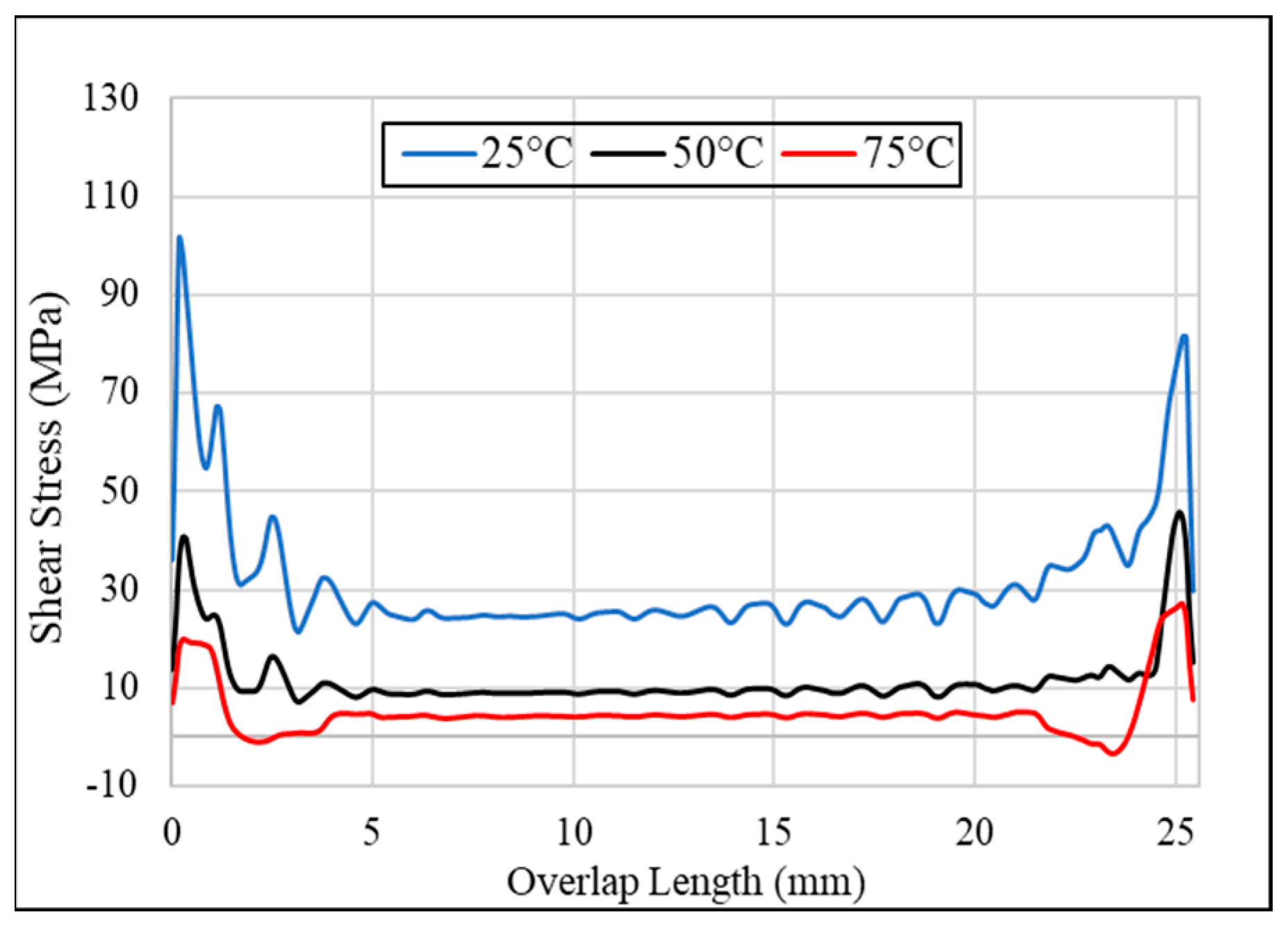
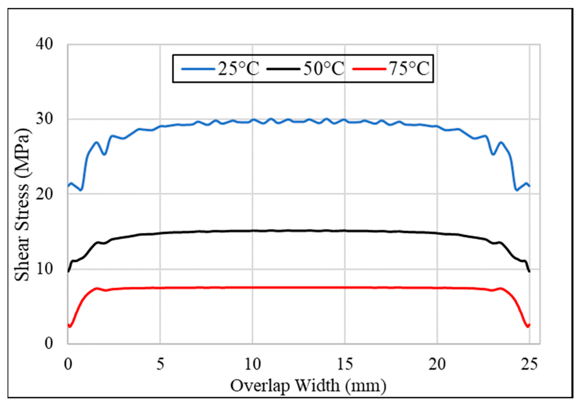
3.3. Effect of Temperature and Alumina Nanoparticles on Peel and Shear Stresses

Adding aluminum oxide, Al2O3, nanoparticles to the adhesive makes it stiff with high elastic modulus and increases the adhesive’s strength [32,34]. Table 3 shows a comprehensive comparison between peel stress and shear stress after adding 1.5 wt% of Al2O3 nanoparticles into the neat adhesive at different temperatures.
After analyzing the Table 3, a trend can be seen when looking at it from left to right and top to bottom. Figure 14, Figure 15, Figure 16 and Figure 17 shows the trend for peel stress distributions with Al2O3 nanoparticles in the adhesive at locations A, B, C and D respectively.
Shear stress occurs when adjacent layers move in opposite directions when a tensile load is applied. From Table 3, it can be seen that the change in the shear stress increased more at 75 °C when Al2O3 nanoparticles were added to a neat adhesive. This showed that for a tensile load at 75 °C, the adhesive showed resistance to the load, unlike in the case of the neat adhesive. This allows the adhesive to be used at elevated temperatures. The different trends regarding the shear stress distributions with Al2O3 nanoparticles in the adhesive at locations A, B, C and D are given in Figure 18, Figure 19, Figure 20 and Figure 21, respectively.
Generally, at room temperature, peak peel and shear stresses experience reduction, whereas the peak stresses are increased when the temperature increases. Taking the case of stresses at location B, adding the nanoparticles at 25 °C decreased the peel stress by 2%, which signified that the adhesive material became less stiff. The peak peel and peak shear stress reduced after the inclusion of the Al2O3 nanoparticles. This reduction can be correlated by comparing Figure 7 and Figure 15, which show similar behavior of reduction of peak peel and shear stresses. Table 3 also shows a significant reduction of over 19% in peak shear stress at room temperatures after adding Al2O3 nanoparticles, signifying less stiffness and more ductility of the material, leading to bearing more load, unlike the neat adhesive, which was stiffer at room temperature. The reduction in peak shear stress can be correlated with Figure 11 and Figure 19. The same trend for peel and shear stresses was observed in the other locations, A, C, and D, and can be correlated with Figure 6, Figure 8, Figure 9, Figure 14, Figure 16 and Figure 17 for peel stress, and Figure 10, Figure 12, Figure 13, Figure 18, Figure 20 and Figure 21 for shear stress. The result showed that adding nanoparticles reduces the chance of early failure in the adhesive. Moreover, the peak stresses were at the ends of the adhesive, which meant that failure would start from the end and travel toward the center, but it would not happen as early as it would in the case of the neat adhesive due to the Al2O3 nanoparticles. As the adhesive was analyzed at 50 °C and 75 °C, adding Al2O3 nanoparticles showed promising results. Considering the same case of location B, the peak peel and shear stresses increased by 5.7% and 4.9%, respectively, at 50 °C and increased by 11.4% and 9.2%, respectively, at 75 °C. This showed that the adhesive becomes stiffer at higher temperatures and can be used at elevated temperatures. The same trend for peel and shear stresses was observed in other locations and can be correlated with Figure 7, Figure 9, Figure 15 and Figure 17 for peel stress, and Figure 10, Figure 13, Figure 18 and Figure 21 for shear stress. At 50 °C and 75 °C, the stresses were low, which signifies minimal resistance to applied displacement that incurred, and that the neat adhesive was not suitable to use at high temperatures. Although Epocast 50-Al adhesive became brittle, stiffer, and more resistant to deformation and early fracture initiation when 1.5 wt% of Al2O3 nanoparticles were added, this caused an increase in both stresses.

4. Conclusions

In this study, peel and shear stresses were analyzed at four different locations on the adhesive of a three-dimensional SLJ having two kinds of adherends (composite carbon fiber and aluminum adherend). The Epocast 50-A1/946 epoxy was used as a neat adhesive, and 1.5 wt% aluminum oxide, Al2O3, nanoparticles were added to the epoxy to analyze the change in the elastic behavior of the adhesive. The SLJ was numerically analyzed at three different temperatures (25 °C, 50 °C, and 75 °C) to observe the effect of temperature on the stresses and elastic behavior of the neat and nanoparticle-added adhesives. It was concluded that adding Al2O3 nanoparticles into the adhesive improved the properties of the epoxy at higher temperatures. It was evident from the obtained results that the rise in peel stress at the locations were more resistant to tensile loading at 50 °C and 75 °C temperatures as compared to the neat adhesive, therefore adding stiffness to the adhesive. It was also observed that the adhesive region of the SLJ experienced higher stresses near the edges, when observing the joint perpendicular to the length dimension. Moreover, it was observed that locations A and B were more vulnerable to damage initiation, as the peak of stresses lay near the edges, indicating that the crack initiation would take place close to the edges, which were along the length of the adhesive and propagate towards the center, leading to ultimate failure. Stating the statistics at location A for using adhesive with Al2O3 nanoparticles showed that peel stress and shear stress decreased by 1.3% and 19%, respectively, at 25 °C. The results showed that an adhesive with aluminum oxide nanoparticles has less stiffness than a neat adhesive, which would be beneficial for holding against more force than a neat adhesive. The peel and shear stresses showed an increase of 2.7% and 7.7%, respectively, at 50 °C, and 10.7% and 8.7%, respectively, at 75 °C for location A. The same pattern was observed for the other locations (i.e., B, C, and D). This concludes that the adhesive becomes stiffer at a higher temperature compared to a neat adhesive. This showed that the adhesive stands against more force than a neat adhesive due to the increase in stiffness. The proposed methodology can be extended to investigate the effect of temperature and the inclusion of nanoparticles on stress behavior at different locations in non-uniform single-lap joints.

Author Contributions

Conceptualization, M.H., A.M. and Y.S.R.; data curation, M.H.; formal analysis, M.H. and M.U.A.; funding acquisition, Y.S.R.; investigation, M.H. and M.M.; methodology, A.M.; software, M.M. and M.U.A.; supervision, Y.S.R.; validation, A.M. and A.Z.; writing—original draft, M.H. and A.M.; writing—review and editing, M.M., A.Z., M.U.A. and Y.S.R. All authors have read and agreed to the published version of the manuscript.

Funding

This work was supported by the National Research Foundation of Korea (NRF) grant funded by the Korea government (MSIT) (No. 2020R1A2C1013693) and the Technology Innovation Program-(20016102, Development of 1.2 kV Gallium oxide power semiconductor devices technology and RS-2022-00144027, Development of 1.2 kV-class low-loss gallium oxide transistor) funded by the Ministry of Trade, Industry & Energy (MOTIE, Korea).

Institutional Review Board Statement

Not applicable.

Informed Consent Statement

Not applicable.

Data Availability Statement

All data that support the findings of this study are included within the article.

Conflicts of Interest

The authors declare no conflict of interest.

Nomenclature

Al2O3Aluminum oxide (alumina)
CFRPCarbon fiber-reinforced polymer
SLJsSingle-lap joints
FEMFinite element modeling
CZMCohesive zone model

References

  1. De Vries, K.; Adams, D.O. Mechanical testing of adhesive joints. Chapter 2002, 6, 193–234. [Google Scholar]
  2. Campilho, R.D.S.G.; De Moura, M.; Ramantani, D.; Morais, J.; Domingues, J. Tensile behaviour of three-dimensional carbon-epoxy adhesively bonded single-and double-strap repairs. Int. J. Adhes. Adhes. 2009, 29, 678–686. [Google Scholar] [CrossRef]
  3. Li, J.; Yan, Y.; Zhang, T.; Liang, Z. Experimental study of adhesively bonded CFRP joints subjected to tensile loads. Int. J. Adhes. Adhes. 2015, 57, 95–104. [Google Scholar] [CrossRef]
  4. Alves, D.; Campilho, R.; Moreira, R.; Silva, F.; Da Silva, L. Experimental and numerical analysis of hybrid adhesively-bonded scarf joints. Int. J. Adhes. Adhes. 2018, 83, 87–95. [Google Scholar] [CrossRef]
  5. Watson, C. Engineering Design with adhesives. In Handbook of Adhesion by D. E. Packham; Sons, J.W., Ed.; Wiley: Hoboken, NJ, USA, 2005. [Google Scholar]
  6. Dixon, D.G. Aerospace applications of adhesives. In Handbook of Adhesion by D. E. Packham; Sons, J.W., Ed.; Wiley: Hoboken, NJ, USA, 2005. [Google Scholar]
  7. Kinloch, A.J. Adhesion and Adhesives: Science and Technology; Springer Science & Business Media: Berlin, Germany, 1987. [Google Scholar]
  8. Adams, R.D.; Comyn, J.; Wake, W.C. Structural Adhesive Joints in Engineering; Springer Science & Business Media: Berlin, Germany, 1997. [Google Scholar]
  9. Ebnesajjad, S. Adhesives Technology Handbook; William Andrew: Norwich, NY, USA, 2008. [Google Scholar]
  10. Lucas, F.M.; da Silva, A.Ö.; Adams, R.D. Handbook of Adhesion Technology, 2nd ed.; Springer: Berlin/Heidelberg, Germany, 2011. [Google Scholar]
  11. Naito, K.; Onta, M.; Kogo, Y. The effect of adhesive thickness on tensile and shear strength of polyimide adhesive. Int. J. Adhes. Adhes. 2012, 36, 77–85. [Google Scholar] [CrossRef]
  12. Da Silva, L.F.; Lopes, M.J.C. Joint strength optimization by the mixed-adhesive technique. Int. J. Adhes. Adhes. 2009, 29, 509–514. [Google Scholar] [CrossRef]
  13. Araújo, H.; Machado, J.; Marques, E.; Da Silva, L. Dynamic behaviour of composite adhesive joints for the automotive industry. Compos. Struct. 2017, 171, 549–561. [Google Scholar] [CrossRef]
  14. Banea, M.; Rosioara, M.; Carbas, R.; Da Silva, L. Multi-material adhesive joints for automotive industry. Compos. Part B Eng. 2018, 151, 71–77. [Google Scholar] [CrossRef]
  15. Reis, P.N.; Ferreira, J.; Antunes, F. Effect of adherend’s rigidity on the shear strength of single lap adhesive joints. Int. J. Adhes. Adhes. 2011, 31, 193–201. [Google Scholar] [CrossRef]
  16. Jairaja, R.; Naik, G.N. Single and dual adhesive bond strength analysis of single lap joint between dissimilar adherends. Int. J. Adhes. Adhes. 2019, 92, 142–153. [Google Scholar]
  17. Korta, J.; Mlyniec, A.; Uhl, T. Experimental and numerical study on the effect of humidity-temperature cycling on structural multi-material adhesive joints. Compos. Part B Eng. 2015, 79, 621–630. [Google Scholar] [CrossRef]
  18. Ribeiro, T.; Campilho, R.; da Silva, L.F.; Goglio, L. Damage analysis of composite–aluminium adhesively-bonded single-lap joints. Compos. Struct. 2016, 136, 25–33. [Google Scholar] [CrossRef]
  19. Rahmani, A.; Choupani, N. Experimental and numerical analysis of fracture parameters of adhesively bonded joints at low temperatures. Eng. Fract. Mech. 2019, 207, 222–236. [Google Scholar] [CrossRef]
  20. Adamvalli, M.; Parameswaran, V. Dynamic strength of adhesive single lap joints at high temperature. Int. J. Adhes. Adhes. 2008, 28, 321–327. [Google Scholar] [CrossRef]
  21. Nguyen, T.-C.; Bai, Y.; Al-Mahaidi, R.; Zhao, X.-L. Time-dependent behaviour of steel/CFRP double strap joints subjected to combined thermal and mechanical loading. Compos. Struct. 2012, 94, 1826–1833. [Google Scholar] [CrossRef]
  22. Ashcroft, I.; Hughes, D.; Shaw, S.; Wahab, M.A.; Crocombe, A. Effect of temperature on the quasi-static strength and fatigue resistance of bonded composite double lap joints. J. Adhes. 2001, 75, 61–88. [Google Scholar] [CrossRef]
  23. Rahmani, A.; Choupani, N.; Kurtaran, H. Thermo-fracture analysis of composite-aluminum bonded joints at low temperatures: Experimental and numerical analyses. Int. J. Adhes. Adhes. 2019, 95, 102422. [Google Scholar] [CrossRef]
  24. Barbosa, A.Q.; Da Silva, L.; Abenojar, J.; Figueiredo, M.; Öchsner, A. Toughness of a brittle epoxy resin reinforced with micro cork particles: Effect of size, amount and surface treatment. Compos. Part B Eng. 2017, 114, 299–310. [Google Scholar] [CrossRef]
  25. Jojibabu, P.; Zhang, Y.; Prusty, B.G. A review of research advances in epoxy-based nanocomposites as adhesive materials. Int. J. Adhes. Adhes. 2020, 96, 102454. [Google Scholar] [CrossRef]
  26. Chu, C.-W.; Zhang, Y.; Obayashi, K.; Kojio, K.; Takahara, A. Single-lap joints bonded with epoxy nanocomposite adhesives: Effect of organoclay reinforcement on adhesion and fatigue behaviors. ACS Appl. Polym. Mater. 2021, 3, 3428–3437. [Google Scholar] [CrossRef]
  27. da Silva, C.; Barbosa, A.; Carbas, R.; Marques, E.; Akhavan-Safar, A.; Da Silva, L. Influence of cork microparticles on the fracture type in single lap joints. Proc. Inst. Mech. Eng. Part C J. Mech. Eng. Sci. 2021, 235, 497–507. [Google Scholar] [CrossRef]
  28. Hülagü, B.; Ünal, H.Y.; Acar, V.; Khan, T.; Aydın, M.R.; Aydın, O.A.; Gök, S.; Pekbey, Y.; Akbulut, H. Low-velocity impact and bending response of graphene nanoparticle-reinforced adhesively bonded double strap joints. J. Adhes. Sci. Technol. 2021, 35, 2391–2409. [Google Scholar] [CrossRef]
  29. Taheri, F. Improvement of the Performance of Structural Adhesive Joints with Nanoparticles and Numerical Prediction of Their Response. In Structural Adhesive Joints: Design, Analysis and Testing; John Wiley & Sons: Hoboken, NJ, USA, 2020; pp. 35–78. [Google Scholar]
  30. Scarselli, G.; Corcione, C.; Nicassio, F.; Maffezzoli, A. Adhesive joints with improved mechanical properties for aerospace applications. Int. J. Adhes. Adhes. 2017, 75, 174–180. [Google Scholar] [CrossRef]
  31. Khashaba, U. Dynamic analysis of scarf adhesive joints in CFRP composites modified with Al2O3-nanoparticles under fatigue loading at different temperatures. Compos. Part A Appl. Sci. Manuf. 2021, 143, 106277. [Google Scholar] [CrossRef]
  32. Gupta, S.K.; Shukla, D.K.; Bharti, A. Effect of alumina nanoparticles on shear strength of epoxy adhesive: Experimental and finite element analysis. In Proceedings of the 2017 International Conference on Advances in Mechanical, Industrial, Automation and Management Systems (AMIAMS), Allahabad, India, 3–5 February 2017; pp. 307–313. [Google Scholar]
  33. Khashaba, U.; Aljinaidi, A.; Hamed, M. Nanofillers modification of Epocast 50-A1/946 epoxy for bonded joints. Chin. J. Aeronaut. 2014, 27, 1288–1300. [Google Scholar] [CrossRef] [Green Version]
  34. Nassiraei, H.; Rezadoost, P. Stress Concentration Factors in Tubular T/Y-Joints Strengthened with FRP Subjected to Compressive Load in Offshore Structures. Int. J. Fatigue 2020, 140, 105719. [Google Scholar] [CrossRef]
  35. Nassiraei, H.; Rezadoost, P. Parametric Study and Formula for SCFs of FRP-Strengthened CHS T/Y-Joints under out-of-Plane Bending Load. Ocean. Eng. 2021, 221, 108313. [Google Scholar] [CrossRef]
  36. Nassiraei, H.; Rezadoost, P. Stress Concentration Factors in Tubular T/Y-Connections Reinforced with FRP under in-Plane Bending Load. Mar. Struct. 2021, 76, 102871. [Google Scholar] [CrossRef]
  37. Khashaba, U.; Aljinaidi, A.; Hamed, M. Development of CFRE composite scarf adhesive joints with SiC and Al2O3 nanoparticle. Compos. Struct. 2015, 128, 415–427. [Google Scholar] [CrossRef]
  38. Taotao, Z.; Wenbo, L.; Wei, X.; Ying, Y. Numerical simulation of single-lap adhesive joint of composite laminates. J. Reinf. Plast. Compos. 2018, 37, 520–532. [Google Scholar] [CrossRef]
  39. Moya-Sanz, E.M.; Ivañez, I.; Garcia-Castillo, S.K. Effect of the geometry in the strength of single-lap adhesive joints of composite laminates under uniaxial tensile load. Int. J. Adhes. Adhes. 2017, 72, 23–29. [Google Scholar] [CrossRef]
  40. Elices, M.; Guinea, G.V.; Gómez, J.; Planas, J. The Cohesive Zone Model: Advantages, Limitations and Challenges. Eng. Fract. Mech. 2002, 69, 137–163. [Google Scholar] [CrossRef]
Figure 1. The geometry of single-lap joint (not to scale).
Coatings 12 01865 g001
Figure 2. Boundary and Loading Conditions on Single-Lap Joint, SLJ (Not to Scale).
Coatings 12 01865 g002
Figure 3. Mesh adapted for single-lap joint model.
Coatings 12 01865 g003
Figure 4. Selected specific locations to determine peel stress and shear stress.
Coatings 12 01865 g004
Figure 5. Validation of numerical model [36].
Coatings 12 01865 g005
Figure 6. Peel stress distribution at location A of SLJ with neat adhesive at different temperatures.
Coatings 12 01865 g006
Figure 7. Peel stress distribution at location B of SLJ with neat adhesive at different temperatures.
Coatings 12 01865 g007
Figure 8. Peel stress distribution at location C of SLJ with neat adhesive at different temperatures.
Coatings 12 01865 g008
Figure 9. Peel stress distribution at location D of SLJ with neat adhesive at different temperatures.
Coatings 12 01865 g009
Figure 10. Shear stress distribution at location A of SLJ with neat adhesive at different temperatures.
Coatings 12 01865 g010
Figure 11. Shear stress distribution at location B of SLJ with neat adhesive at different temperatures.
Coatings 12 01865 g011
Figure 12. Shear stress distribution at location C of SLJ with neat adhesive at different temperatures.
Coatings 12 01865 g012
Figure 13. Shear stress distribution at location D of SLJ with neat adhesive at different temperatures.
Coatings 12 01865 g013
Figure 14. Peel stress distribution at location A of SLJ with Al2O3 nanoparticles in the adhesive at different temperatures.
Coatings 12 01865 g014
Figure 15. Peel stress distribution at location B of SLJ with Al2O3 nanoparticles in the adhesive at different temperatures.
Coatings 12 01865 g015
Figure 16. Peel stress distribution at location C of SLJ with Al2O3 nanoparticles in the adhesive at different temperatures.
Coatings 12 01865 g016
Figure 17. Peel stress distribution at location D of SLJ with Al2O3 nanoparticles in the adhesive at different temperatures.
Coatings 12 01865 g017
Figure 18. Shear stress distribution at location A of SLJ with Al2O3 nanoparticles in the adhesive at different temperatures.
Coatings 12 01865 g018
Figure 19. Shear stress distribution location B of SLJ with Al2O3 nanoparticles in the adhesive at different temperatures.
Coatings 12 01865 g019
Figure 20. Shear stress distribution at location C of SLJ with Al2O3 nanoparticles in the adhesive at different temperatures.
Coatings 12 01865 g020
Figure 21. Shear stress distribution at location D of SLJ with Al2O3 nanoparticles in the adhesive at different temperatures.
Coatings 12 01865 g021
Table 1. Material properties of Al 5083, neat adhesive, and adhesive with Al2O3 nanoparticles.
Material PropertyAluminum 5083Neat/Epoxy [37]STDEV [37]1.5 wt% Al2O3/Epoxy [37]STDEV [37]
Elastic Modulus (E) (GPa)703.4320.433.6760.04
Poisson Ratio (v)0.330.32-0.314-
Shear Modulus G (GPa)26.41.450.271.570.06
Tensile Strength (MPa)31775.531.5675.881.85
Shear Strength (MPa)19050.711.3553.910.52
Table 2. Material Properties of T300/QY8911 CFRP Composite Lamina [38].
Material PropertiesValue
Longitudinal Tensile Modulus; E1 (GPa)135
Transverse Tensile Modulus; E2 = E3 (GPa)8.8
In-plane Shear Modulus; G12 = G13 (GPa)4.5
Transverse Modulus; G23 (GPa)4.0
Poisson’s Ratio; v12 = v130.33
Poisson’s Ratio; v230.45
Table 3. Comparison of Percentage Change in Peel Stress and Shear Stress with the Inclusion of 1.5 wt% Al2O3 Nanoparticles in Epocast 50-A1 Adhesive.
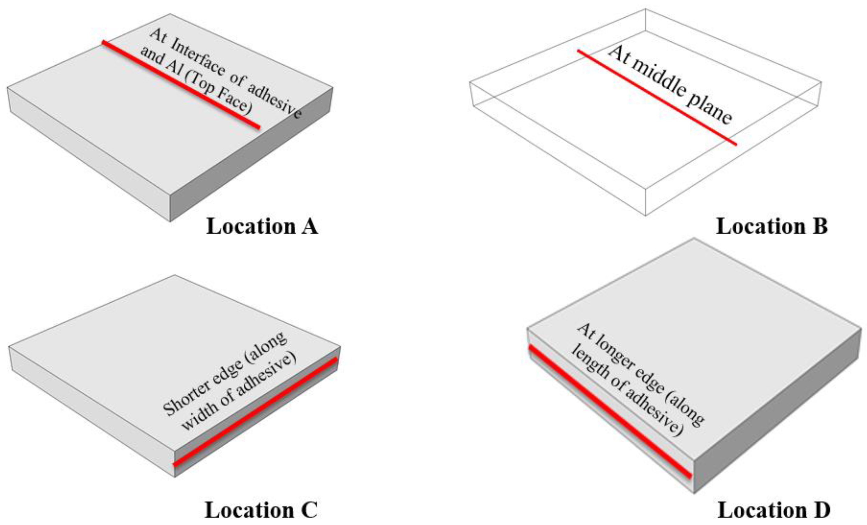
Top Face (Interface) (Location A)
Temperature25 °C50 °C75 °C
Peel Stress MPa (Max)−1.34%2.72%10.74%
Shear Stress MPa (Max)−19.66%7.71%8.72%
Middle Plane (Location B)
Temperature25 °C50 °C75 °C
Peel Stress MPa (Max)−2.70%5.77%11.44%
Shear Stress MPa (Max)−19.45%4.96%9.21%
Shorter Edge (Along Width) (Location C)
Temperature25 °C50 °C75 °C
Peel Stress MPa (Max)1.70%−4.75%−0.29%
Shear Stress MPa (Max)−4.16%7.15%14.42%
Longer Edge (Along Length) (Location D)
Temperature25 °C50 °C75 °C
Peel Stress MPa (Max)−0.80%6.77%21.24%
Shear Stress MPa (Max)−20.72%9.06%23.83%
Publisher’s Note: MDPI stays neutral with regard to jurisdictional claims in published maps and institutional affiliations.

