
A Dichroic Beamsplitter for the Laser Protection of Infrared Detectors
 ,
, 
Abstract
:1. Introduction
2. Experimental Procedure
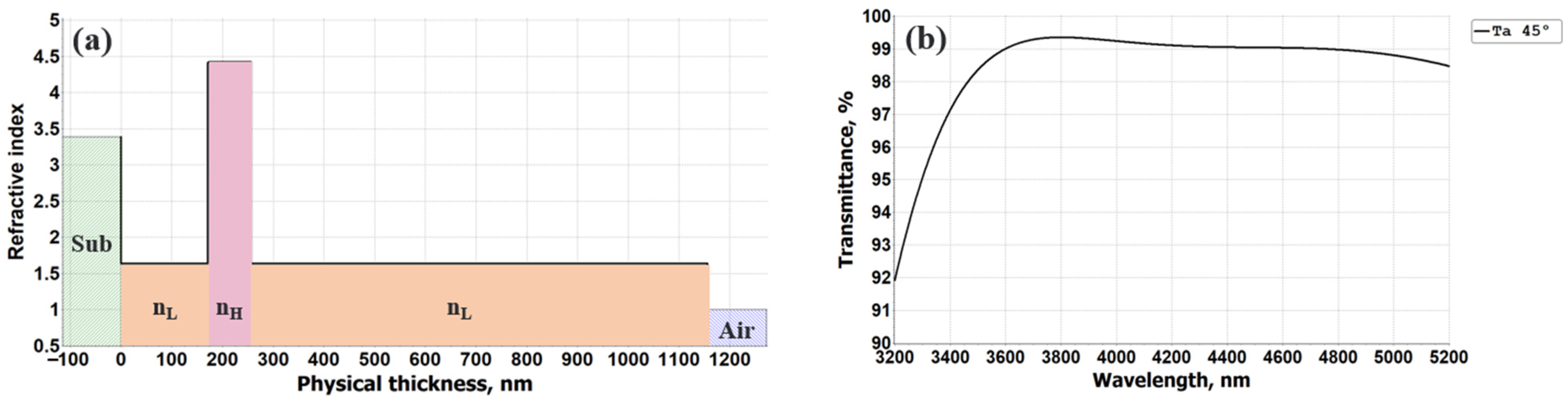
2.1. Design
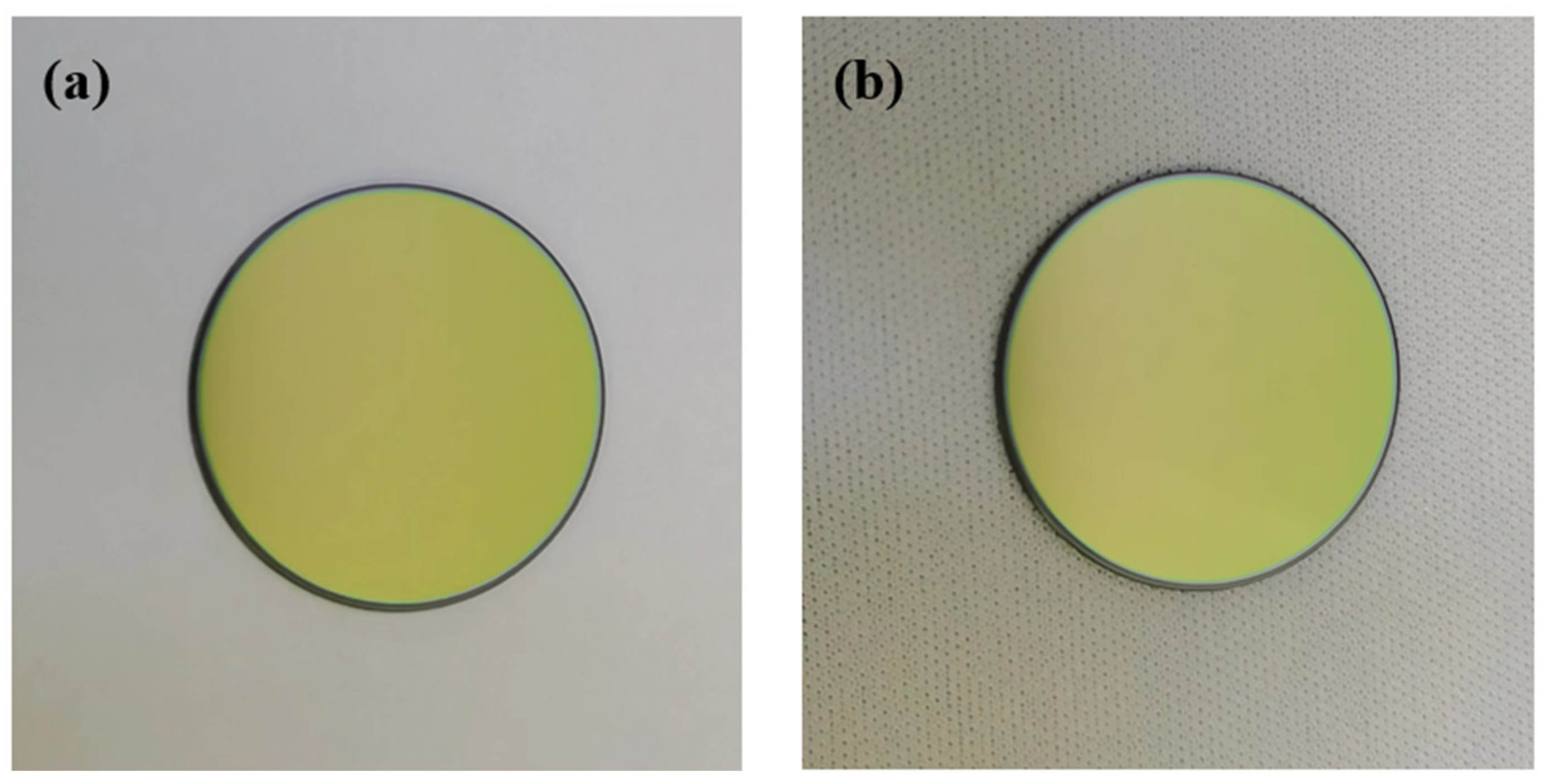
2.2. Fabrication
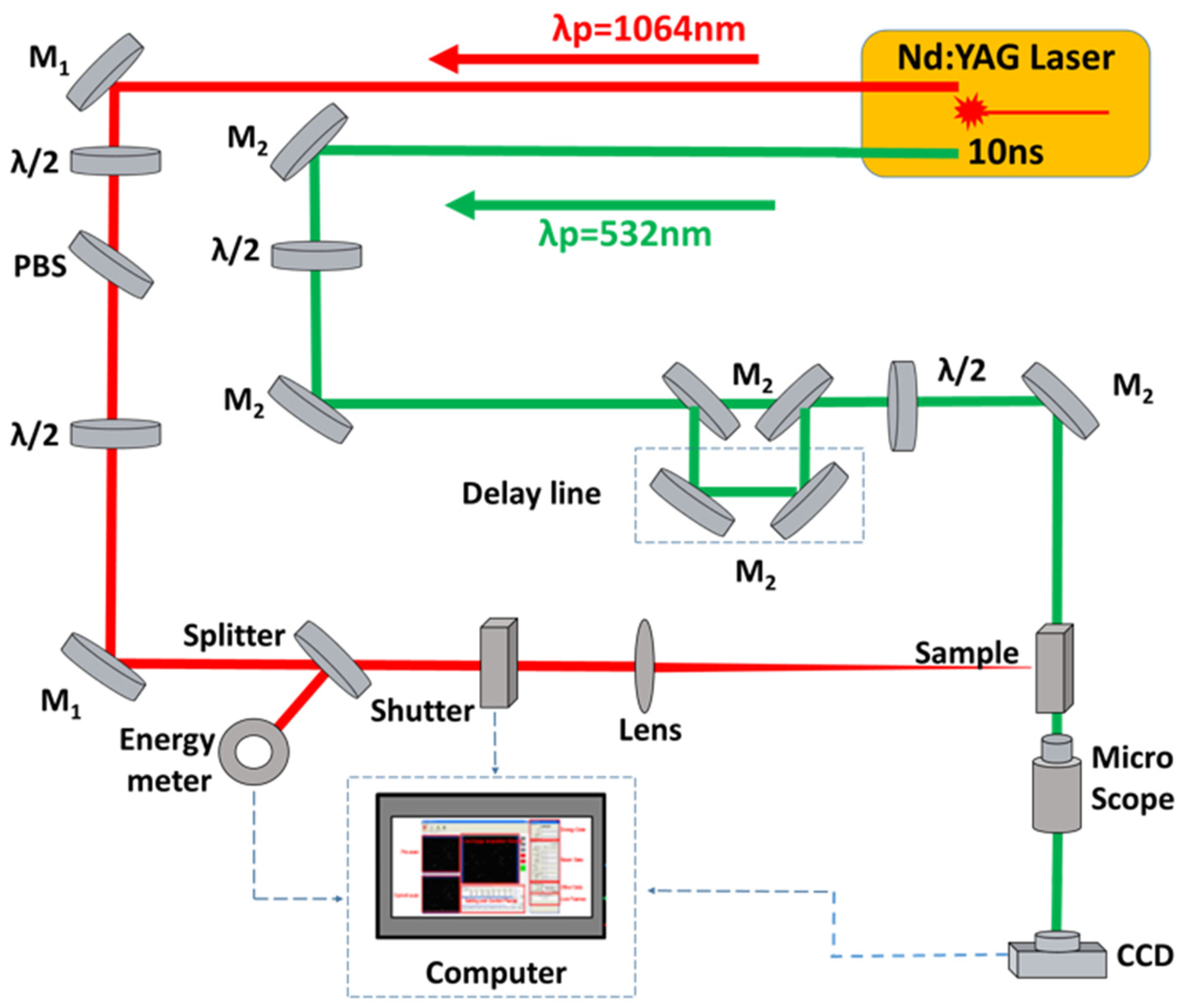
2.3. Characterization
3. Results and Discussion
3.1. Spectra Measurements
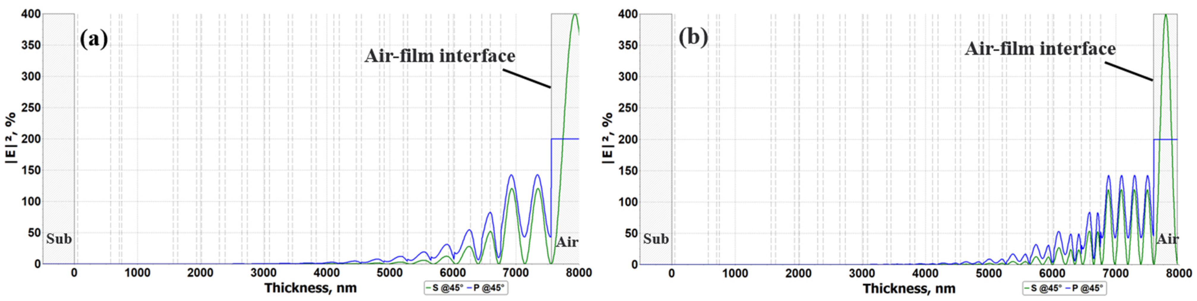
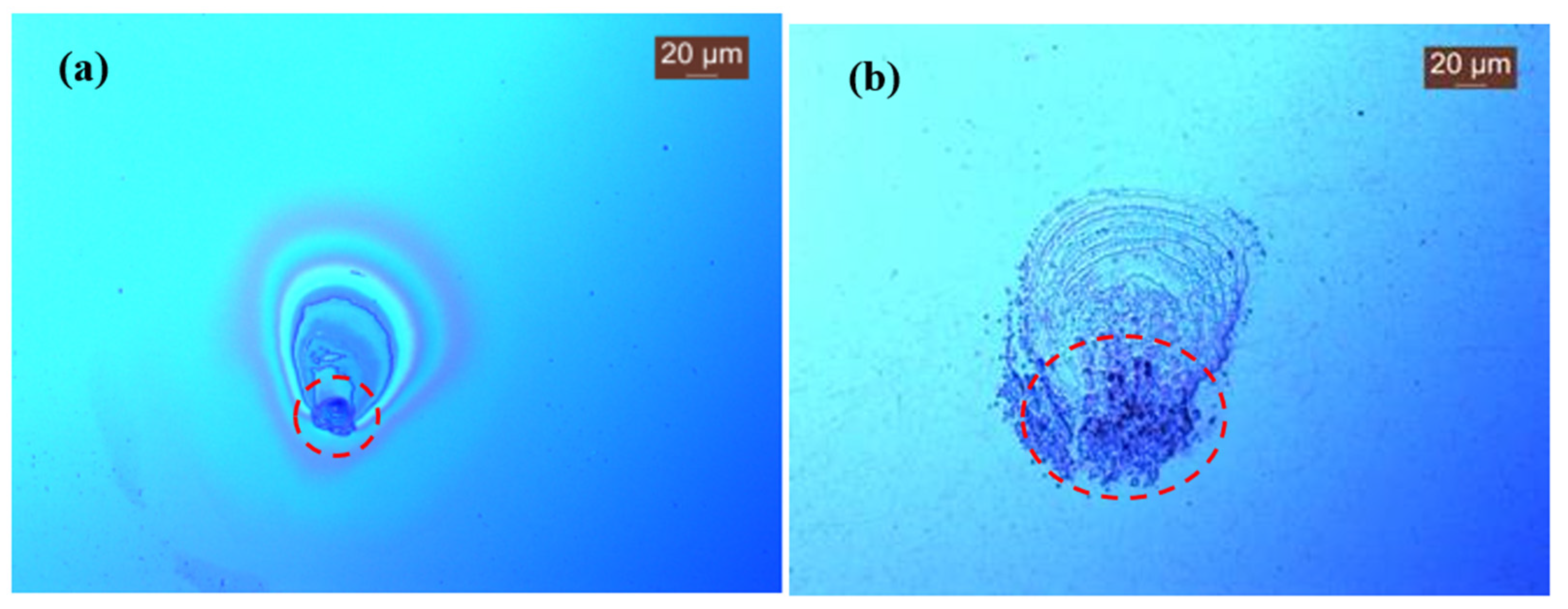
3.2. LIDT Measurements and Analysis
3.3. Environmental Test
4. Conclusions
Author Contributions
Funding
Institutional Review Board Statement
Informed Consent Statement
Data Availability Statement
Conflicts of Interest
References
- Rogalski, A. History of infrared detectors. Opto-Electron. Rev. 2012, 20, 279–308. [Google Scholar] [CrossRef]
- Wang, Y.; Meng, C.; Ma, W. Review of reliability research on infrared detector. In Proceedings of the Seventh Symposium on Novel Photoelectronic Detection Technology and Applications, Kunming, China, 5–7 November 2021; Volume 11763, pp. 186–192. [Google Scholar]
- Karim, A.; Andersson, J.Y. Infrared detectors: Advances, challenges and new technologies. IOP Conf. Ser. Mater. Sci. Eng. 2013, 51, 012001. [Google Scholar] [CrossRef] [Green Version]
- Peters, A. Blinding Laser Weapons. Med. War 1996, 12, 107–113. [Google Scholar] [CrossRef] [PubMed]
- Zöckler, M.C. Commentary on Protocol IV on Blinding Laser Weapons. Yearb. Int. Humanit. Law 1998, 1, 333–340. [Google Scholar] [CrossRef]
- Yang, H.X.; Chen, F.M.; Li, Z.M.; Wu, Z.Q. Study on the Engineering Factors of Jamming Effect of the Laser Blinding and Computer Simulation. In Proceedings of the 2008 International Conference on Computer Science and Software Engineering, IEEE, Washington, DC, USA, 12–14 December 2008; Volume 4, pp. 134–137. [Google Scholar] [CrossRef]
- Harris, D.C. Materials for Infrared Windows and Domes: Properties and Performance; SPIE Press: Bellingham, WA, USA, 1999. [Google Scholar]
- Kumar, S.; Shankar, A.; Kishore, N.; Mukherjee, C.; Kamparath, R.; Thakur, S. Laser induced damage threshold of Ta2O5 and Ta2O5/SiO2 films at 532 and 1064 nm. Optik 2019, 176, 438–447. [Google Scholar] [CrossRef]
- Kala, M.B.; Bandyopadhyay, P.K.; Nautiyal, B.B. Thorium free antireflection coating in MWIR region on Silicon optics. Infrared Phys. Technol. 2012, 55, 409–411. [Google Scholar] [CrossRef]
- Zhang, Y.; Xiong, S.; Huang, W.; Zhang, K.; Tian, X. Six-spectral antireflection coating on zinc sulfide simultaneously effective for the visible, near-IR, and long wavelength IR regions. Surf. Coat. Technol. 2019, 359, 1–5. [Google Scholar] [CrossRef]
- Amotchkina, T.; Trubetskov, M.; Schulz, M.; Pervak, V. Comparative study of NIR-MIR beamsplitters based on ZnS/YbF3 and Ge/YbF3. Opt. Express 2019, 27, 5557–5569. [Google Scholar] [CrossRef] [Green Version]
- Hu, H.; Fan, Z.; Luo, F. Laser-Induced Damage of a 1064-nm ZnS/MgF(2) Narrow-Band Interference Filter. Appl. Opt. 2001, 40, 1950–1956. [Google Scholar] [CrossRef]
- Wang, G.; Ling, X.; Liu, X.; Fan, Z. Effects of deposition temperature on characterization and laser-induced damage threshold of YbF3 films. Opt. Laser Technol. 2013, 49, 274–278. [Google Scholar] [CrossRef]
- Zhang, Y.; Zhang, K.; Huang, W.; Xiong, S. Determination of infrared refractive index of ZnS and YbF3 thin films by spectroscopy. Optik 2018, 170, 321–327. [Google Scholar] [CrossRef]
- Guo, M.; Yi, K.; Cui, X.; Shao, S.; Hu, G.; Zhao, J.; He, H.; Shao, J. Design and preparation of UV-visible-shortwave near infrared cut-off and mid-infrared antireflection coating. Optik 2021, 227, 165470. [Google Scholar] [CrossRef]
- Deng, X.; Su, J. Laser Protection Properties of Multi-Band Non-Regularized Highly Reflective Films. Coatings 2022, 12, 1614. [Google Scholar] [CrossRef]
- Xu, C.; Yi, P.; Fan, H.L.; Qi, J.W.; Yang, S.; Qiang, Y.H.; Liu, J.T.; Li, D.W. Preparation of high laser-induced damage threshold Ta2O5 filmsz. Appl. Surf. Sci. 2014, 309, 194–199. [Google Scholar] [CrossRef]
- Sathasivam, S.; Williamson, B.A.D.; Kafizas, A.; Althabaiti, S.A.; Obaid, A.Y.; Basahel, S.N.; Scanlon, D.O.; Carmalt, C.J.; Parkin, I.P. Computational and experimental study of Ta2O5 thin films. J. Phys. Chem. C 2017, 121, 202–210. [Google Scholar] [CrossRef]
- Xu, C.; Qiang, Y.; Zhu, Y.; Shao, J.; Fan, Z.; Han, J. Effects of deposition parameters on laser-induced damage threshold of Ta2O5 films. Opt. Laser Technol. 2010, 42, 497–502. [Google Scholar] [CrossRef]
- Jena, S.; Tokas, R.B.; Tripathi, S.; Rao, K.D.; Udupa, D.V.; Thakur, S.; Sahoo, N.K. Influence of oxygen partial pressure on microstructure, optical properties, residual stress and laser induced damage threshold of amorphous HfO2 thin films. J. Alloys Compd. 2019, 771, 373–381. [Google Scholar] [CrossRef]
- Jena, S.; Tokas, R.B.; Rao, K.D.; Thakur, S.; Sahoo, N.K. Annealing effects on microstructure and laser-induced damage threshold of HfO2/SiO2 multilayer mirrors. Appl. Opt. 2016, 55, 6108–6114. [Google Scholar] [CrossRef]
- Wang, Y.; Cheng, X.; Shao, J.; Zheng, C.; Chen, A.; Zhang, L. The Damage Threshold of Multilayer Film Induced by Femtosecond and Picosecond Laser Pulses. Coatings 2022, 12, 251. [Google Scholar] [CrossRef]
- Xu, C.; Xiao, Q.; Ma, J.; Jin, Y.; Shao, J.; Fan, Z. High temperature annealing effect on structure, optical property and laser-induced damage threshold of Ta2O5 films. Appl. Surf. Sci. 2008, 254, 6554–6559. [Google Scholar] [CrossRef]
- Tikhonravov, A.V.; Trubetskov, M.K. Optilayer Thin Film Software. Available online: https://www.optilayer.com (accessed on 10 August 2022).
- Tikhonravov, A.V.; Trubetskov, M.K.; Amotchkina, T.V. Optical parameters of oxide films typically used in optical coating production. Appl. Opt. 2011, 50, C75–C85. [Google Scholar] [CrossRef] [PubMed]
- Amotchkina, T.; Trubetskov, M.; Hahner, D.; Pervak, V. Characterization of e-beam evaporated Ge, YbF3, ZnS, and LaF3 thin films for laser-oriented coatings. Appl. Opt. 2020, 59, A40–A47. [Google Scholar] [CrossRef] [PubMed]
- Furman, S.A.; Tikhonravov, A.V. Basics of Optics of Multilayer Systems; Atlantica Séguier Frontieres: Gif-sur-Yvette, France, 1992. [Google Scholar]
- Berning, P.H. Use of Equivalent Films in the Design of Infrared Multilayer Antireflection Coatings. J. Opt. Soc. Am. 1962, 52, 431–436. [Google Scholar] [CrossRef]
- Yenisoy, A.; Yeşilyaprak, C.; Tüzemen, S. High efficient ultra-broadband anti-reflection coating on silicon for infrared applications. Infrared Phys. Technol. 2019, 100, 82–86. [Google Scholar] [CrossRef]
- Tian, X.; Xiong, S.; Zhang, K. Improvement and coordination of spectral and mechanical properties of bandpass filter on silicon substrate for the infrared range. Opt. Eng. 2020, 59, 055106. [Google Scholar] [CrossRef]
- ISO 21254-2; Lasers and Laser-Related Equipment—Test Methods for Laser-Induced Damage Threshold—Part 2: Threshold Determination. International Organization for Standardization: Geneva, Switzerland, 2011.
- Liu, G.; Kuang, D.; Song, L.; Xu, C.; Yan, C. Mechanism in damage variation of nanosecond laser-induced damage of germanium sheets in vacuum. Opt. Laser Technol. 2023, 157, 108663. [Google Scholar] [CrossRef]


| Test | Specification | Sample No. | Result |
|---|---|---|---|
| Temperature cycle | 2 h each at 55 °C and −40 °C with 30 min change over | Sample 1 | Passed |
| Humidity | 24 h, 95% to 100% (RH); 49 ± 1 °C | Sample 2 | Passed |
| Abrasion | 50 rubs by cheesecloth | Sample 3 | Passed |
| Adhesion | 1 pull by scotch tape | Sample 4 | Passed |
| Salt spray | 24 h, 6.7–7.4 pH, 25 °C | Sample 5 | Passed |
Publisher’s Note: MDPI stays neutral with regard to jurisdictional claims in published maps and institutional affiliations. |
© 2022 by the authors. Licensee MDPI, Basel, Switzerland. This article is an open access article distributed under the terms and conditions of the Creative Commons Attribution (CC BY) license (https://creativecommons.org/licenses/by/4.0/).
Share and Cite
Cao, J.; Jiang, B.; Jiao, H.; Niu, X.; Zhang, J.; Zhang, Z.; Cheng, X.; Wang, Z. A Dichroic Beamsplitter for the Laser Protection of Infrared Detectors. Coatings 2022, 12, 1861. https://doi.org/10.3390/coatings12121861
Cao J, Jiang B, Jiao H, Niu X, Zhang J, Zhang Z, Cheng X, Wang Z. A Dichroic Beamsplitter for the Laser Protection of Infrared Detectors. Coatings. 2022; 12(12):1861. https://doi.org/10.3390/coatings12121861
Chicago/Turabian StyleCao, Jian, Binbin Jiang, Hongfei Jiao, Xinshang Niu, Jinlong Zhang, Zhong Zhang, Xinbin Cheng, and Zhanshan Wang. 2022. "A Dichroic Beamsplitter for the Laser Protection of Infrared Detectors" Coatings 12, no. 12: 1861. https://doi.org/10.3390/coatings12121861