Article

Predicting the Residual Stress of Amorphous Al2O3-Y2O3 Nano-Laminated Deuterium Permeation Barrier under Thermal Cycles

1
National Engineering Research Center of Nonferrous Metals Materials and Products for New Energy, GRINM Group Co., Ltd., Beijing 100088, China
2
GRIMAT Engineering Institute Co., Ltd., Beijing 101407, China
3
General Research Institute for Nonferrous Metals, Beijing 100088, China
4
GRINM (GuangDong) Institute for Advanced Materials and Technology, Shenzhen 518055, China
5
National Center for Materials Service Safety, University of Science and Technology Beijing, Beijing 100083, China
6
State Key Laboratory for Performance and Structure Safety of Petroleum Tubular Goods and Equipment Materials, CNPC Tubular Goods Research Institute, Xi’an 710077, China
*
Authors to whom correspondence should be addressed.
These authors contributed equally to this work.
Coatings 2022, 12(11), 1780; https://doi.org/10.3390/coatings12111780
Submission received: 24 October 2022 / Revised: 12 November 2022 / Accepted: 13 November 2022 / Published: 21 November 2022

Abstract

:
Al2O3-Y2O3 laminated coating can be applied in fusion reactors to prevent fuel leakage and radiological hazard. However, the residual stress induced by the thermal cycles during the operation of the reactor can cause the failure of the coating. In order to analyze the problem, finite element models of Al2O3-Y2O3 laminated coatings with 600 nm of total thickness and different layout were analyzed. The max principal stress site in the coatings is located at the sub-top layer. The max principal stress in laminated coating with the Y2O3 sub-top decreases from 657 MPa for a two-layer coating (300 nm) to 598 MPa for a four-layer coating (150 nm). On the contrary, if Al2O3 is the sub-top layer, the max principal stress increases from 463 MPa for a two-layer coating (300 nm) to 495 MPa for a four-layer coating (150 nm). The result shows that the more deformable amorphous Al2O3 layer in the laminated coating system is more influential to the thermal stress.

1. Introduction

Fusion energy has become attractive as a clean energy source to solve future energy issues [1,2]. However, tritium, the fuel of the fusion reactor, is radioactive and can easily permeate through structural materials such as 316L stainless steel, resulting in fuel leakages and hydrogen embrittlement of the structure, and thus threatening the safe operation of the fusion reactor [2,3]. In the tritium cycles of fusion reactor as shown in Figure 1, tritium loss is mainly due to its leakage into the coolant and forming tritiated water (HTO) then exhausted to the outside environment [2,4].
Hanchar and Kazim analyzed the tritium leakage of starfire-Interim tokamak reactor and obtained a stunning result that the tritium losses in the primary coolant loop exceed 103 Ci/day, obviously unacceptable by any standard [4]. The HTO molecule can easily be incorporated into the human body, where it has a half residual life of 10 days according to ICRP Publication 71 [5]. Tritium permeation is dangerous and must be prevented. Currently, the most used solution to this critical problem is preparing a ceramic coating on the structural steel. Because tritium is strictly controlled, deuterium and hydrogen are commonly used as substitutes to analyze the performance of coatings in experiments. Oxide ceramics such as Al2O3, Cr2O3, Y2O3, Er2O3, TiO2 and their composites are the most common choice because they can effectively suppress the deuterium permeation and their cost is acceptable [6,7,8,9,10,11,12,13]. Among them, Al2O3 has a high permeation resistant factor (PRF), high strength, strong thermodynamic stability, and relatively low cost and easy deposition method. Thus, Al2O3 is an ideal candidate for preparing a deuterium permeation barrier. Al2O3 has been applied in fusion industry acting as highly radiation-resistant material for optical and dielectric windows [14,15]. However, the vast thermal mismatch between the Al2O3 coating and the substrate, 316L stainless steel, e.g., can cause huge residual stress in the system, resulting in the peeling-off of the coating [16,17,18,19]. Many studies have been conducted to analyze the residual thermal stress and failure behavior of the coating/substrate system in order to determine the failure mechanism and the optimization procedures. Preparing multiple-layer coating or gradient coating is the most widely used solution to the thermal mismatch problem currently [20,21,22,23,24,25,26,27,28]. Some researchers found that cracks and defects in the coating could produce a significant effect on the fracture of the coating. Low density micro crack will dramatically degrade the coating [29,30]. However, most of them focus on monolayer or bilayer micron-thick coatings. Resent findings showed that nano-thick coatings have better performance than micron ones [31,32]. Furthermore, our previous findings [33] indicates that the interface between layers in a bilayer Al2O3/Y2O3 coating if not introducing much defects can act as a barrier that blocks the permeation of tritium. Thus, the composite coating has a higher permeation resistance than the single layer ones. To explore the effect of introducing multiple interfaces in a nano-thick laminated coating on the thermal cycle behavior of the coating, the residual thermal stress in Al2O3-Y2O3 laminated coatings was investigated via finite element analysis. The effect of the layer thickness, coating lay-out, and temperature difference on the residual thermal stress of Al2O3-Y2O3 laminated coating were analyzed. This research is a preliminary work for understanding the thermal cycle behavior of a nano-thick laminated deuterium permeation barrier and the optimization of the preparation of such coating.

2. Materials and Methods

Static structural analysis via ANSYS 19 was used to simulate the thermal stress of the coating/substrate systems under thermal cycles. Max principal stress was selected as the major evaluation factor, because oxide ceramics are brittle and sensitive to b tensile stress.

2.1. Analytic Model

The finite-element analysis model settings are similar to our previous work on bilayer Al2O3/Y2O3 and Y2O3/Al2O3 coatings [33]. Static structural finite-element analysis was applied and displacements are defined as solution factors corresponding to each nodal element. Loads are derived from forces and displacements. The finite-element analysis software uses interpolation functions to figure out the elemental stiffness matrix to calculate the stress and strain increments at any point in the model.
The total strain vector, { ε }, is the sum of elastic strain increment vector, { ε e l } , and thermal strain increment vector, { ε t h } :
{ ε } = { ε e l } + { ε t h } .
Within each element, the displacement, { δ } , for any given element, ( e ) can be calculated using following equation:
{ ε } = { B } { δ } e ,
where { B } is the strain matrix.
Hooke’s law can be applied to figure out the elastic stress increment vector, { σ e l } :
{ σ e l } = { D } { ε e l } ,
where { D } is the elastic matrix for any given material that defined by its elastic modulus, E, and Poisson’s ratio, ν , at a given temperature.
The relationship between the thermal stress increment vector, { ε t h } , and the temperature increment, T , can be calculated as follows:
{ ε t h } = { α } T ,
where α is the thermal expansion coefficient.
The principle of virtual work is applied to figure out the stress:
{ δ } T { F } e = { ε } T { σ } d x d y d z .
Substitution of Equations (3)–(5) derives:
{ F } e = { B } T { D } { ε e } d x d y d z .
The equilibrium equation can be applied to calculate the element stiffness matrix, { K } :
{ K } { δ } = { F }
The load vector { F } . only includes the thermal force in the thermal shock condition, Thus, the thermal stress can be derived as follows:
{ F } T e = { B } T { D } { B } { α } d x d y d z .

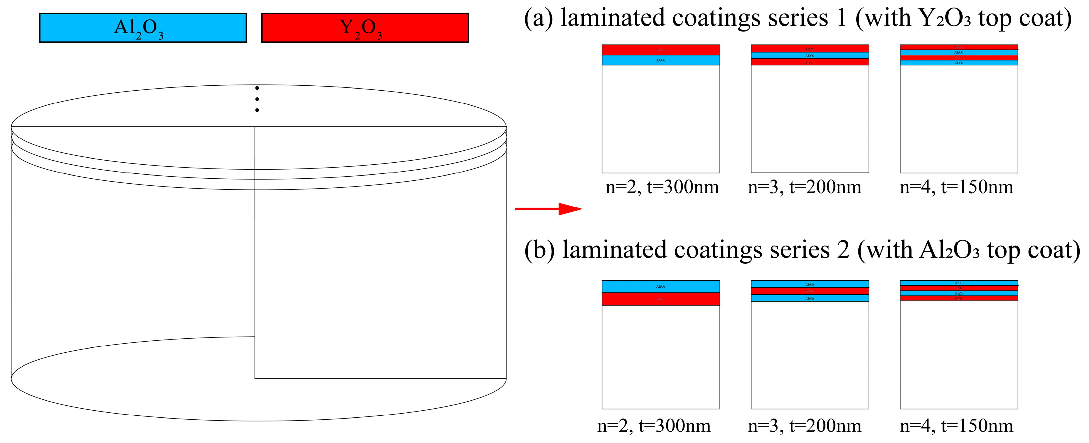
2.2. Model Geometry and Material Properties

The modeling was based on the composite coatings in our previous study [25]. The scanning electron microscope (SEM) (Hitachi-S4800, Hitachi, Tokyo, Japan) images of the coatings deposited on 316L stainless steel by radio-frequency magnetron sputtering are shown in Figure 2. As the figure shows, the interface between each layer is considerably smooth and clear with no visible defects. It indicates that each layer of the coating is dense and homogeneous. Further description about the deposition and the performance of the coatings can be found in [32].
The model consists of two major parts. One was the substrate modeled as a cylinder which was 1 mm in diameter and 0.5 mm in thickness. The other is the laminated coating, where the thickness of each layer is t i , i is the order of the layer from substrate to the top, and t 0 is the thickness of the substrate. Laminated coatings with different deposition orders were analyzed. The model configuration is shown in Table 1.
Each layer is uniform and homogenous. Thus, it is possible and proper to use two-dimensional axisymmetric models to simplify the analysis, as shown in Figure 3. The properties of the materials involved are listed in Table 2.

2.3. Meshing

In order to build a nano-thick coating model with enough numerical scale for meshing, same methods applied in our previous study was used [33]. The micron was set as the standard unit of length in all models. Thus, all related parameters were converted to match the change (e.g., the Young’s modulus of the Y2O3 is set to 0.12 N/μm3). The elements in each layer are squares with 25 nm side length, while the element edge length of the substrate varies from 25 nm to 50 μm. Each model consists of approximately 500,000 elements and the average element quality is over 0.97. The mesh condition is shown in Figure 4.

2.4. Boundary Condition and Load

Frictionless supports were applied to the left edge and the bottom edge of the model, which prevented each edge from translating along its normal direction or rotating around itself. Bonded constraints were applied to each contact pair, causing the contacting surfaces to bond together. In other words, no relative tangential movements would occur on the interfaces. All models were cooled from a 700 °C stress-free state to a given terminal temperature, which simulated the condition of specimens in previous study; specimens annealed at 700 °C for stress relief purposes [32]. The boundary condition is shown in Figure 4.

3. Result and Discussion

3.1. Max Principal Stress in Laminated Coating with Different Layout, Number of Layers and Temperature

All laminated coatings were 600 nm thick, with the number of layers varying from two to four. The stress fields of each model were analyzed, and were also compared with the corresponding monolayer coatings with the same layer thickness. As shown in Figure 5, the max principal stress in the laminated coating series 1 (with Y2O3 top coat) increases as the layer thickness decreases, from 463 MPa for a two-layer coating to 495 MPa for a four-layer coating. While the max principal stress in the laminated coating series 2 (with Al2O3 top coat) decreases as the layer thickness decreases, from 657 MPa for a two-layer coating to 598 MPa for a four-layer coating. Moreover, the max principal stress in series 1 is about 25% lower than the series 2. The result shows that the laminated coating series 1 have better thermal cycle endurance than the series 2, which agrees to the previous experiment on bilayer coatings [32]. However, the max principal in both composite coatings is much higher than the monolayer coating with same layer thickness. The max principal stress in monolayer amorphous Al2O3 coating is only about 68 MPa, while the max principal stress in monolayer Y2O3 coating is about 230 MPa, which is much lower than that in the amorphous Al2O3 coating. The result reveals that the monolayer amorphous Al2O3 coating has better thermal cycle endurance than the monolayer Y2O3 coating, which agrees with the coefficient of thermal expansion (CTE) differences between the coating and the substrate in Table 2. The CTE of amorphous Al2O3 is 14.7 × 10⁻⁶ [37], while the CTE of Y2O3 is 8 × 10⁻⁶ [36], and the CTE of 316L SS is 17.3 × 10⁻⁶ [24]. The max principal stress in both kinds of monolayer coating is almost even for the layer thickness from 150 nm to 300 nm. The thermal cycle endurances of monolayer amorphous Al2O3 and monolayer Y2O3 coating show little relevance to the coating thickness in the given condition of the simulation. Furthermore, the thermal stress of both kinds of laminated coatings is an order higher than that of the monolayer amorphous Al2O3 coating and about three times higher than that of the Y2O3 coating. The thermal mismatch between amorphous Al2O3 and Y2O3 is so large that becomes the major factor that determines the thermal residual stress in the coating system. It indicates that preparing this kind of laminated composite for better tritium permeation resistance comes at the cost of thermal cycle endurance.
As shown in Figure 6, the max principal stress in the laminated coating occurs in the layer adjacent to the top coat. The overall max principal stress in the layer beneath the top coat is the highest in all layers. The max principal stress distribution result agrees with the max stress data as shown in Figure 5, both showing that the thermal mismatch between the Y2O3 and amorphous Al2O3 is the major impact factor to the max principal stress in the coating system. The max principal stress site in bilayer Al2O3/Y2O3 coating is at the interface between the top coat and adjacent layer 25 nm from the edge. That in the bilayer Y2O3/Al2O3 coating is at the edge of the interface between the top coat and the adjacent layer 25 nm from the interface. On the other hand, the max principal stress site in three-layer and four-layer laminated coating locates inversely in the layers beneath the top coat compared with bilayer coating. The max principal stress sites in Y2O3/Al2O3/Y2O3 and Al2O3/Y2O3/Al2O3/Y2O3 coatings are at the interface between the sub-top layer and the adjacent layer beneath it 25 nm from the edge. The max principal stress sites in Al2O3/Y2O3/Al2O3 and Y2O3/Al2O3/Y2O3/Al2O3 coatings are at the edge of the sub-top layer 25 nm from the edge between the sub-top layer and the layer beneath. The result indicates that the sub-top layer is the most venerable in the Al2O3-Y2O3 laminated coating system with the most severe stress concentration. The surface of the sub-top layer is the most likely crack initiation site that causes the final peeling-off of the laminated coating. It can be concluded that Y2O3 is not good to be directly composited with amorphous Al2O3 due to the vast thermal mismatch between them.
The decrease of max principal stress in the laminated coating series 2 (with Al2O3 top coat) as the layer thickness decreases can be explained by the stress singularity theory. At the edge of the interface, where there is a sudden change of stiffness, exists a stress singular point. Furthermore, the residual thermal stress, σ p , at the singular point can be express as follows when the singular region is small:
σ p = K r λ ,   r < r 0 ,
where r 0 is the vicinity zone of the stress singularity, and K is the stress intensity factor. Both K and λ are functions of the Poisson’s ratio, Young’s modulus, and the contact angles of the two layers. As the thickness of layers, t, increases, the λ decreases, the stress singularity zone becomes wider and the σ p , at the edge increases. As a result, for laminated coating series 2 (with Al2O3 top coat), the more the layers, the thinner the layer, and the smaller the residual thermal stress will be [39]. However, as the number of layers increases, it can become increasingly difficult to deposit a laminated coating without critical defects. Furthermore, a less deformable layer could withstand stress with less deformation and have less impact to the coating system. In other words, there will be less stress singularity effect. Therefore, the max principal stress in laminated coating series 1 with more deformable top coat, Y2O3, and a less deformable sub-top coat Al2O3 withstanding the highest local stress in the coating system is lower than that in the series 2. An opposite effect, the increase in the max principal stress as the layer thickness increases, occurs due to the thinner Al2O3 layer to withstand the extra tensile stress caused by the strain of the adjacent less deformable Y2O3 layer.
The stress field of the model 3 (316L/Al2O3/Y2O3/Al2O3/Y2O3) cooling from a 700 °C stress-free state to different temperatures was simulated, with the result shown in Figure 7. It shows that the max principal stress declines linearly as the temperature difference decreases. This simulation result agrees with Equation (4) for thermal stress. However, if the crystallization and phase changes are taken into consideration, the actual result will be different from the simulation [40].

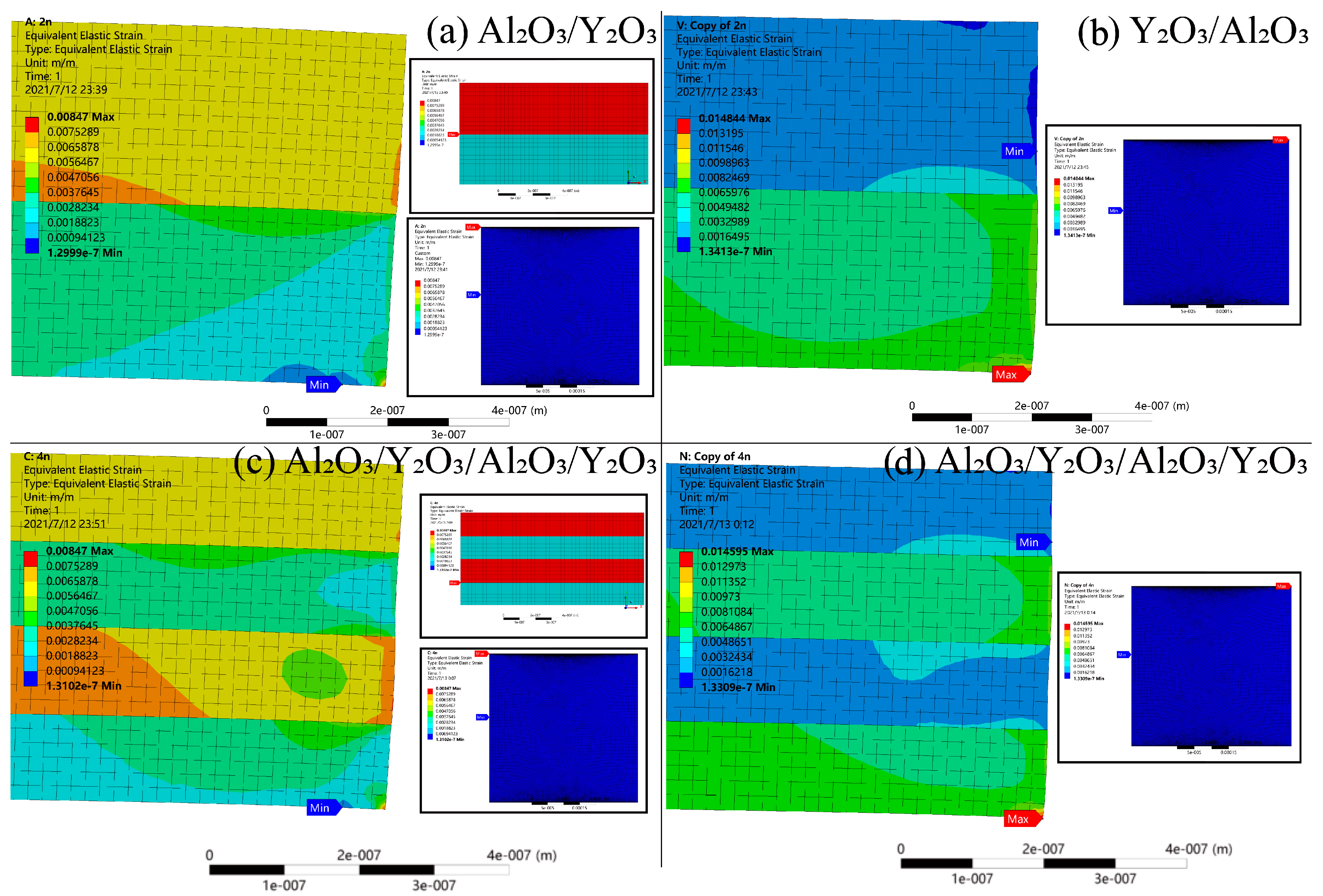
3.2. Equivalent Elastic Strain and Neutral Plane in Laminated Coating

As shown in Figure 8, the equivalent elastic strain distribution shows that the neutral plane with nearly no strain is located at the horizontal center line of the substrate. This agrees with the theory proposed by Nix and colleagues [40]. However, the max elastic strain site in laminated coating series 1 is located near the center of the coating due to the accumulating of strain while the max elastic strain site in laminated coating series 2 is located at the edge of the coating system. The more severe elastic strain in coating series 2 agrees with the stress analysis result that it endures greater stress. The result also shows that the contact surfaces have a great impact on the stress distribution as the elastic stress distribution differs to the max principal stress distribution.
The bending moment, M, for each layer can be determined by
M = ( E 1 υ ) t s 3 12 κ ,
where E is the Young’s modulus, υ is the Poisson’s ratio, I = t s 3 12 , is the moment of inertia for bending, and κ is the bending curvature.
By definition, the neutral plane fulfills the condition
M = 0 = i = 0 n z i z i + 1 ε B i ( z s ) d z ,
where B = ( E 1 υ ) is the biaxial modulus of the layers.
By matching the adjacent layers with the same amount of misfit strain, this leads to
s = 1 2 i = 0 n B i ( z i + 1 2 z i 2 ) i = 0 n B i ( z i + 1 z i ) ,
which for a bilayer coating leads to
s = 1 2 B 0 t 0 2 + B 1 ( t 1 2 + 2 t 0 t 1 ) B 0 t 0 + B 1 t 1 .
As the substrate is much thicker and stiffer, B 0 t 0 B 1 t 1 , this relation can thus be simplified to s = t 0 / 2 .
It can be derived that the curvature of the multiple-layer coating system is
κ = i 1 n B i ε i m i s f i t { 1 2 ( z i + 1 2 z i 2 ) s ( z i + 1 z i ) } i = 0 n B i 3 { ( z i + 1 s ) 3 ( z i s ) 3 } .
The result shows that the model proposed by Nix and his colleague [40] calculating the stress in multilayer system can predict the strain and stress in the system with acceptable accuracy.

4. Conclusions

In Al2O3-Y2O3 laminated coating, the amorphous Al2O3 layers with lower Young’s modulus are more influential in the max principal stress in the thermal cycle behavior of the coating. The max principal stress in the laminated coating series 1, with a brittle Al2O3 sub-top layer withstanding the highest local stress in the system, increases as the layer thickness decreases. This is because, as the layer thickness decreases, the stress singularity zone at the edge of the interface decreases and its stress concentration effect increases. However, with a ductile Y2O3 sub-top layer (series 2), the max principal stress in the laminated coating increases as the layer thickness decreases. This is because the thinner the Y2O3 layers, the less stiffness they have to resist the extra tensile stress caused by the adjacent Al2O3 layer. The max principal stress in the laminated coating series 2 is about 25% higher than that in the laminated coating series 1 with the same layer thickness, meaning it is more prone to failure in dynamic thermal loadings. Thus, this kind of coating structures should be avoided. Both laminated coatings endure much greater stress than the monolayer coating, about three times higher than the monolayer Y2O3 coating and an order higher than the monolayer Al2O3 coating. The local stress concentrated most severely in the sub-top layer in laminated coating indicating the sub-top layer is the most likely position that the coating begins to fail into under thermal cycles. The residual thermal stress in the laminated coating declines linearly as the temperature difference declines, if the crystallization and phase changes are not taken into consideration. The neutral plane with no strain in the laminated coating is at the horizontal center line of the substrate.

Author Contributions

Conceptualization, Q.Y. and L.J.; methodology, K.H.; software, K.H.; validation, W.W., H.L.; formal analysis, K.H., B.Y.; investigation, H.L.; resources, W.X.; data curation, R.C.; writing—original draft preparation, K.H.; writing—review and editing, K.H., M.L.; visualization, H.L.; supervision, Y.L.; project administration, Q.Y. and L.H.; funding acquisition, J.M. All authors have read and agreed to the published version of the manuscript.

Funding

This research was funded by the Science Center for Gas Turbine Project (P2022-B-IV-009-002), the Opening Project fund of Materials Service Safety Assessment Facilities (MSAF series) and the Science and Technology Planning Project of Guangdong Province, China (2021B0909050001).

Institutional Review Board Statement

Not applicable.

Informed Consent Statement

Not applicable.

Data Availability Statement

Not applicable.

Conflicts of Interest

The authors declare no conflict of interest.

References

  1. Wu, Y. Conceptual Design of the China Fusion Power Plant FDS-II. Fusion Eng. Des. 2008, 83, 1683–1689. [Google Scholar] [CrossRef]
  2. Tanabe, T. Tritium: Fuel of Fusion Reactors; Springer: Tokyo, Japan, 2016. [Google Scholar] [CrossRef]
  3. Fukada, S.; Oya, Y.; Hatano, Y. Review of Recent Japanese Activities on Tritium Accountability in Fusion Reactors. Fusion Eng. Des. 2016, 113, 231–235. [Google Scholar] [CrossRef]
  4. Hanchar, D.R.; Kazimi, M.S. A Tritium Permeation Model for Conceptual Fusion Reactor Designs. J. Fusion Energy 1983, 3, 47–61. [Google Scholar] [CrossRef]
  5. Annals of the ICRP. Age-Dependent Doses to Members of the Public from Intake of Radionuclides: Part 4 Inhalation Dose Coefficients; ICRP Publication 71; Ann. ICRP: Oxford, UK, 1995. [Google Scholar]
  6. Smith, D.L.; Konys, J.; Muroga, T.; Evitkhin, V. Development of Coatings for Fusion Power Applications. J. Nucl. Mater. 2002, 307–311, 1314–1322. [Google Scholar] [CrossRef]
  7. Huang, Q.; Li, C.; Wu, Q.; Liu, S.; Gao, S.; Guo, Z.; Yan, Z.; Huang, B.; Song, Y.; Zhu, Z.; et al. Progress in Development of CLAM Steel and Fabrication of Small TBM in China. J. Nucl. Mater. 2011, 417, 85–88. [Google Scholar] [CrossRef]
  8. Otsuka, T.; Goto, K.; Yamamoto, A.; Hashizume, K. Effects of Shot-Peening on Permeation and Retention Behaviors of Hydrogen in Alpha Iron. Fusion Eng. Des. 2018, 136, 509–512. [Google Scholar] [CrossRef]
  9. Yang, H.; Shao, Z.; Wang, W.; Ji, X.; Li, C. A Composite Coating of GO-Al2O3 for Tritium Permeation Barrier. Fusion Eng. Des. 2020, 156, 111689. [Google Scholar] [CrossRef]
  10. Kulsartov, T.V.; Hayashi, K.; Nakamichi, M.; Afanasyev, S.E.; Shestakov, V.P.; Chikhray, Y.V.; Kenzhin, E.A.; Kolbaenkov, A.N. Investigation of Hydrogen Isotope Permeation through F82H Steel with and without a Ceramic Coating of Cr2O3-SiO2 Including CrPO4 (out-of-Pile Tests). Fusion Eng. Des. 2006, 81, 701–705. [Google Scholar] [CrossRef]
  11. Houben, A.; Rasiński, M.; Gao, L.; Linsmeier, C. Tungsten Nitride as Tritium Permeation Barrier. Nucl. Mater. Energy 2020, 24, 100752. [Google Scholar] [CrossRef]
  12. Wang, L.; Yang, J.J.; Feng, Y.J.; Li, F.Z.; Liao, J.L.; Yang, Y.Y.; Feng, K.M.; Liu, N. Preparation and Characterization of Al2O3 Coating by MOD Method on CLF-1 RAFM Steel. J. Nucl. Mater. 2017, 487, 280–287. [Google Scholar] [CrossRef]
  13. Hu, L.; Wei, G.; Yin, R.; Hong, M.; Cheng, T.; Zhang, D.; Zhao, S.; Yang, B.; Zhang, G.; Cai, G.; et al. Significant Hydrogen Isotopes Permeation Resistance via Nitride Nano-Multilayer Coating. Int. J. Hydrogen Energy 2020, 45, 19583–19589. [Google Scholar] [CrossRef]
  14. Averback, R.S.; Ehrhart, P.; Popov, A.I.; Sambeek, A.V. Defects in Ion Implanted And Electron Irradiated MgO and Al2O3. Radiat. Eff. Defects Solids 1995, 136, 169–173. [Google Scholar] [CrossRef]
  15. Popov, A.I.; Lushchik, A.; Shablonin, E.; Vasil’chenko, E.; Kotomin, E.A.; Moskina, A.M.; Kuzovkov, V.N. Comparison of the F-type Center Thermal Annealing in Heavy-Ion and Neutron Irradiated Al2O3 Single Crystals. Nucl. Instrum. Methods Phys. Res. Sect. B Beam Interact. Mater. At. 2018, 433, 93–97. [Google Scholar] [CrossRef]
  16. Li, H.; Ke, Z.; Xue, L.; Yan, Y. A Novel Low-Temperature Approach for Fabricating α-Al2O3-Based Ceramic Coating as Tritium Permeation Barrier. Fusion Eng. Des. 2017, 125, 567–572. [Google Scholar] [CrossRef]
  17. Han, Q.; Geng, Y.; Setchi, R.; Lacan, F.; Gu, D.; Evans, S.L. Macro and Nanoscale Wear Behaviour of Al-Al2O3 Nanocomposites Fabricated by Selective Laser Melting. Compos. Part B Eng. 2017, 127, 26–35. [Google Scholar] [CrossRef]
  18. Yang, F.; Xiang, X.; Lu, G.; Zhang, G.; Tang, T.; Shi, Y.; Wang, X. Tritium Permeation Characterization of Al2O3/FeAl Coatings as Tritium Permeation Barriers on 321 Type Stainless Steel Containers. J. Nucl. Mater. 2016, 478, 144–148. [Google Scholar] [CrossRef]
  19. Huang, J.; Xie, H.; Luo, L.-M.; Zan, X.; Liu, D.-G.; Wu, Y.-C. Preparation and Properties of FeAl/Al2O3 Composite Tritium Permeation Barrier Coating on Surface of 316L Stainless Steel. Surf. Coat. Technol. 2020, 383, 125282. [Google Scholar] [CrossRef]
  20. Liu, S.; Ju, X.; Qiu, J.; Chen, G.; Sun, J.; Xin, Y.; Ma, F. Tritium-Permeation-Barrier Properties of Erbium Oxide (TPB) Coating on CLAM Steel. Fusion Eng. Des. 2019, 138, 347–351. [Google Scholar] [CrossRef]
  21. Xu, L.; Liu, S.; Wang, M.; Zhou, S. Crack Initiation and Propagation Mechanism of Al2O3-DBC Substrate during Thermal Cycling Test. Eng. Fail. Anal. 2020, 116, 104720. [Google Scholar] [CrossRef]
  22. Liu, H.; Tao, J.; Gautreau, Y.; Zhang, P.; Xu, J. Simulation of Thermal Stresses in SiC-Al2O3 Composite Tritium Penetration Barrier by Finite-Element Analysis. Mater. Des. 2009, 30, 2785–2790. [Google Scholar] [CrossRef]
  23. Liu, Z.; Meng, F.; Yi, L.B. Simulation of the Effects of Different Substrates, Temperature, and Substrate Roughness on the Mechanical Properties of Al2O3 Coating as Tritium Penetration Barrier. Nucl. Sci. Tech. 2019, 30, 62. [Google Scholar] [CrossRef]
  24. Liu, H.; Tao, J.; Zhang, P.; Xu, J. Modeling of Residual Stresses in Functionally Gradient AI2O3 Coating on 316L Substrate. J. Comput. Theor. Nanosci. 2008, 5, 1677–1680. [Google Scholar] [CrossRef]
  25. Stylianou, R.; Velic, D.; Daves, W.; Ecker, W.; Tkadletz, M.; Schalk, N.; Czettl, C.; Mitterer, C. Thermal Crack Formation in TiCN/α-Al2O3 Bilayer Coatings Grown by Thermal CVD on WC-Co Substrates with Varied Co Content. Surf. Coat. Technol. 2020, 392, 125687. [Google Scholar] [CrossRef]
  26. de la Roche, J.; Gómez, P.A.; Alvarado-Orozco, J.M.; Toro, A. Hot Corrosion and Thermal Shock Resistance of Dense-CYSZ/YSZ Bilayer Thermal Barrier Coatings Systems Applied onto Ni-Base Superalloy. J. Eur. Ceram. Soc. 2020, 40, 5692–5703. [Google Scholar] [CrossRef]
  27. Li, B.; Fan, X.; Wang, T.; Zhou, K. Interfacial Fracture Behavior of Double-Ceramic-Layer Thermal Barrier Coating System with Segmented Structure. Eng. Fract. Mech. 2018, 201, 13–28. [Google Scholar] [CrossRef]
  28. Rezaei, S.; Wulfinghoff, S.; Reese, S. Prediction of Fracture and Damage in Micro/Nano Coating Systems Using Cohesive Zone Elements. Int. J. Solids Struct. 2017, 121, 62–74. [Google Scholar] [CrossRef]
  29. Li, B.; Fan, X.; Okada, H.; Wang, T. Mechanisms Governing the Failure Modes of Dense Vertically Cracked Thermal Barrier Coatings. Eng. Fract. Mech. 2018, 189, 451–480. [Google Scholar] [CrossRef]
  30. Seo, S.B.; Bang, I.C. Effects of Al2O3 Nanoparticles Deposition on Critical Heat Flux of R-123 in Flow Boiling Heat Transfer. Nucl. Eng. Technol. 2015, 47, 398–406. [Google Scholar] [CrossRef]
  31. Zhou, C.; Wang, N.; Xu, H. Comparison of Thermal Cycling Behavior of Plasma-Sprayed Nanostructured and Traditional Thermal Barrier Coatings. Mater. Sci. Eng. A 2007, 452–453, 569–574. [Google Scholar] [CrossRef]
  32. Wang, W.; Yu, Q.; Liu, X.; Lu, Z. Preparation of Al2O3/Y2O3 Composite Coating for Deuterium Permeation Reduction. J. Rare Earths 2020, 38, 1237–1242. [Google Scholar] [CrossRef]
  33. Huang, K.; Wang, W.; Yu, Q.; Hao, L.; Mi, J.; Li, S.; Liu, H.; Li, S.; Liu, J.; Wang, J. Simulation of the Residual Stress of the Y2O3/Al2O3 Composite Deuterium Permeation Barrier under Thermal Shock. Int. J. Photoenergy 2021, 2021, 6684802. [Google Scholar] [CrossRef]
  34. Konynenburg, R.A.; McCright, R.D.; Roy, A.K.; Jones, D.A. Engineered Materials Characterization Report for the Yucca Mountain Site Characterization Project Volume 2: Design Data; Lawrence Livermore National Lab: Livermore, CA, USA, 1995.
  35. Shi, C.; Alderman, O.L.G.; Berman, D.; Du, J.; Neuefeind, J.; Tamalonis, A.; Weber, J.K.R.; You, J.; Benmore, C.J. The Structure of Amorphous and Deeply Supercooled Liquid Alumina. Front. Mater. 2019, 6, 38. [Google Scholar] [CrossRef]
  36. Rontu, V.; Nolvi, A.; Hokkanen, A.; Haeggström, E.; Kassamakov, I.; Franssila, S. Elastic and Fracture Properties of Free-Standing Amorphous ALD Al2O3 Thin Films Measured with Bulge Test. Mater. Res. Express 2018, 5, 046411. [Google Scholar] [CrossRef] [Green Version]
  37. Huntz, A.-M.; Andrieux, M.; Vahlas, C.; Sovar, M.-M.; Samelor, D.; Gleizes, A.N. Phase Transformations of Metallorganic Chemical Vapor Deposition Processed Alumina Coatings Investigated by In Situ Deflection. J. Electrochem. Soc. 2007, 154, 63. [Google Scholar] [CrossRef] [Green Version]
  38. Martienssen, W.; Warlimont, H. Springer Handbook of Condensed Matter and Materials Data; Springer: Berlin/Heidelberg, Germany, 2005. [Google Scholar]
  39. Gu, B.; Phelan, P.E. Thermal Peeling Stress Analysis of Thin-Film High-Tc Superconductors. Appl. Supercond. 1998, 6, 19–29. [Google Scholar] [CrossRef]
  40. Nix, W.D. Metallic Thin Films: Stresses and Mechanical Properties. In Metallic Films for Electronic, Optical and Magnetic Applications: Structure, Processing and Properties; Woodhead Publishing: Cambridge, UK, 2013; pp. 353–421. [Google Scholar] [CrossRef]
Figure 1. Tritium cycle and leakage in fusion reactor [2,4].
Coatings 12 01780 g001
Figure 2. SEM images of the nanoscale coatings: (a) Al2O3 [32]; (b) Y2O3 [34]; (c) 316L SS/Al2O3/Y2O3 [32]; (d) 316L SS/Al2O3/Y2O3/Al2O3/Y2O3.
Coatings 12 01780 g002
Figure 3. The geometry of the model: (a) laminated coating series 1 (with Y2O3 top coat); (b) laminated coating series 2 (with Al2O3 top coat).
Coatings 12 01780 g003
Figure 4. Mesh and boundary condition of the finite element.
Coatings 12 01780 g004
Figure 5. Effect of the thickness on the max principal stress of laminated coating and the corresponding monolayer coating.
Coatings 12 01780 g005
Figure 6. Comparison of the max principal stress in laminated coatings and single-layer coatings: (a) Al2O3, t = 300 nm; (b) Al2O3/Y2O3; (c) Y2O3, t = 300 nm; (d) Y2O3/Al2O3; (e) Al2O3, t = 150 nm; (f) Al2O3/Y2O3/Al2O3/Y2O3; (g) Y2O3, t = 150 nm; (h) Y2O3/Al2O3/Y2O3/Al2O3.
Coatings 12 01780 g006
Figure 7. Effect of terminal temperature on the max principal stress.
Coatings 12 01780 g007
Figure 8. Equivalent elastic strain in laminated coatings: (a) Al2O3/Y2O3; (b) Y2O3/Al2O3; (c) Al2O3/Y2O3/Al2O3/Y2O3; (d) Y2O3/Al2O3/Y2O3/Al2O3.
Coatings 12 01780 g008
Table 1. Model configuration.
Structure SeriesNumberStructureTotal Thickness (nm)Layer Thickness (nm)
Series 1
(laminated coatings with Y2O3 top coat)
1316L/Al2O3/Y2O3600300
2316L/Y2O3/Al2O3/Y2O3600200
3316L/Al2O3/Y2O3/Al2O3/Y2O3600150
Series 2
(laminated coatings with Al2O3 top coat)
6316L/Y2O3/Al2O3600300
7316L/Al2O3/Y2O3/Al2O3600200
8316L/Y2O3/Al2O3/Y2O3/Al2O3600150
Table 2. Model configuration.
MaterialDensity (kg/m3)Young’s Modulus (GPa)Poisson’s RatioCoefficient of Thermal
Expansion (CTE)
(10−6 K−1)
316L8000 [24]200 [24]0.25 [34]17.3 [24]
am-Al2O33300 [35]124.3 [36]0.24 [36]14.7 [37]
Y2O35000 [38]120 [38]0.26 [8]8 [38]
Publisher’s Note: MDPI stays neutral with regard to jurisdictional claims in published maps and institutional affiliations.

