Article

A Smart Anticorrosive Epoxy Coating Based on Graphene Oxide/Functional Mesoporous Silica Nanoparticles for Controlled Release of Corrosion Inhibitors

National−Provincial Laboratory of Special Function Thin Film Materials, School of Materials Science and Engineering, Xiangtan University, Xiangtan 411105, China
*
Authors to whom correspondence should be addressed.
Coatings 2022, 12(11), 1749; https://doi.org/10.3390/coatings12111749
Submission received: 26 September 2022 / Revised: 9 November 2022 / Accepted: 11 November 2022 / Published: 15 November 2022
(This article belongs to the Special Issue Multi-Functional Nanostructured Sustainable Coatings)

Abstract

:
When mesoporous nanomaterials and graphene oxide have been used in anti-corrosion coatings, new nanocoatings have attracted greater attention. Adding nano-fillers with special structures and corrosion inhibitors to epoxy coatings has been proven to effectively enhance the corrosion resistance of coatings. However, studies have pointed out that the added corrosion inhibitors are easily degraded by UV light and react with the metal substrate or materials in the coating, resulting in a significant reduction in the service life of the coating. To this end, in this study, the corrosion inhibitor was encapsulated in mesoporous silica with pH response, and the functional silica was composited with graphene oxide to prepare novel graphene oxide/functional mesoporous silica nanoparticles. Coatings with this special filler added have strong anti-corrosion potential and can be applied in marine anti-corrosion contexts, such as containers, in the future. The filler not only has a physical barrier ability but also can effectively prevent the degradation of the inhibitor due to ultraviolet rays. At the same time, in the early stage of corrosion, the release of inhibitors can be effectively controlled by the change in PH to achieve the purpose of preventing corrosion. UV spectrophotometry confirmed the stable encapsulation and controlled release of the inhibitor. Electrochemical-impedance spectroscopy showed that the |Z|0.01 Hz value of the smart anti-corrosion epoxy coating was about 10,000 times higher than that of the pure epoxy coating. Through the FT-IR mapping test, it was found that in the area of mechanical damage, the alkaline environment created by the initial corrosion can induce the release of tannic acid and react with common corrosion products to form iron tannins, which effectively inhibits the further occurrence of corrosion. This method provides an effective method for the design of heavy-duty anti-corrosion coatings.

1. Introduction

Metals involving steel, magnesium, and aluminum and their alloys have been widely used in marine-engineering applications such as marine ships, naval vessels, offshore platforms, and buildings [1]. However, metal corrosion is a serious problem for equipment and production tools in these applications, which not only shortens the service life of metals and creates great safety hazards, but also causes huge economic losses [2]. Organic anti-corrosion coatings are simple, efficient, and economical solutions for protection against metal corrosion, providing a physical barrier to prevent the penetration of corrosive media, greatly reducing corrosion damage to metal materials [3]. At present, epoxy resin coatings are widely used because of their simple construction, low price, and good anti-corrosion effect [4]. However, epoxy-resin coatings tend to generate micropores during curing, resulting in degraded barrier properties [5,6,7]. Therefore, the anticorrosion performance of epoxy-resin coatings still needs to be improved [8]. Adding some nano-fillers with special structures and corrosion inhibitors to epoxy coating areas has been proven to effectively enhance the corrosion resistance of coatings and increase their service life under harsh conditions [9,10,11,12,13,14,15]. How to modify nanofillers into special storage structures is a significant research topic.
This study reports the use of graphene oxide/functional mesoporous silica nanoparticles as fillers for applying a heavy-duty anti-corrosion coating for the first time. The composite filler was prepared by novel and simple preparation methods, achieved the controlled release of corrosion inhibitors by a pH-responsive release system, inhibited corrosion once the corrosion process started, and successfully increased the coating service life.

2. Materials and Methods

2.1. Materials

Graphene oxide (GO) was purchased from XinZhaoye (Guangdong) New Material Co., Ltd. (purity of 99%, Guangzhou, China), tetraethyl orthosilicate (TEOS), cetyltrimethylammonium chloride (CTAC), triethanolamine (TEA), chitosan (CS) with a deacetylation degree of 90% and a molecular weight of 200 kD, methacrylic acid (MAA), modifiers (KH560), N, N-dimethylformamide (DMF), NaCl, potassium persulfate (K2S2O8), and tannic acid (TA) purchased from Aladdin Industrial Co. (Shanghai, China). Epoxy resin (EP, CYD 014, epoxy equivalent of 0.12) and its curing agent (P54, active hydrogen equivalent of 327.86) were purchased from Baling Chemical (Yueyang, China) Co., Ltd. The diluents used in the experiments were xylene and n-butanol, which was purchased from Aladdin Industrial Co., Ltd. (Shanghai, China) at a volume ratio of 4:6. Ultrapure water (specific resistance ≥ 18 MΩ·cm) was made in the laboratory, and absolute ethanol (analytical grade) and glacial acetic acid were purchased from Sinopharm Chemical Reagent Co., Ltd., China (Shanghai, China). Test substrates (Q235 steel sheets) were purchased from Biuged Laboratory Instruments Co., Ltd. (Guangzhou, China) [16].

2.2. Synthesis of Smart Anticorrosive Epoxy Coating Based on Graphene Oxide/Functional Mesoporous Silica Nanoparticles

The synthesis pathway is shown in Figure 1. Synthesis of mesoporous silica nanoparticles and functional silica nanoparticles was prepared according to the recently reported protocol [17,18].

2.2.1. Step 0: Synthesis of Mesoporous Silica Nanoparticles

The Stöber method was modified to prepare mesoporous silica nanoparticles (MSNs). Figure 2 shows the synthesis mechanism of mesoporous silica nanoparticles. Specifically, 2 g of CTAC used as the templating agent were dissolved in 50 mL of H2O by continuously stirring at room temperature. Next, 10 mL of ethanol and 6 mL of TEA as the pH regulator were added to the solution, and the mixture was vigorously stirred for 10 min. The prepared solution was heated to 80 °C in an oil bath, and 4 mL of TEOS was added dropwise under rapid stirring. The mixture was refluxed at 80 °C for 2 h, after which it was cooled to room temperature. The nanoparticles were collected by centrifugation (8000 rpm, 10 min). Subsequently, the nanoparticles were cauterized at 600 °C in a muffle furnace for 8 h to resolve the templating agent and obtain MSNs [17].

2.2.2. Step 1: Preparation of Functional Silica Nanoparticles

Figure 3 shows the synthesis mechanism of functional silica nanoparticles. First, 1.6 g of MSNs were added to 300 mL of the aqueous solution containing 2.0 g CS and 4.3 g MAA. The reaction mixture was ultrasonicated for 20 min and then stirred under a nitrogen environment for 0.5 h and heated to 80 °C. After the temperature remained at 80 °C for 10 min, the solution became apparent, and 0.3 g K2S2O8 was added to the reaction mixture. The reaction was maintained at 80 °C under a nitrogen atmosphere for another 2 h with the rotative velocity speed of a mechanical stirrer at 300 rpm. During this period, the milk-white color of the reaction mixture became light yellow. Subsequently, the system temperature was lowered from 80 to 50 °C. Next, 1.0 mL glutaraldehyde was added to the system; after about 10 min, the color of the reaction mixture changed from light yellow to brown. The reaction was continued for another 2 h to proceed ultimately. The obtained products were washed with deionized water three times [18].

2.2.3. Steps 2 and 3: Synthesis of CS/PMAA-MSNs@GO Loaded with Tannic Acid

Figure 4 shows the synthesis mechanism of CS/PMAA-MSNs@GO loaded with tannic acid (TA). First, 0.1 g GO (1.0 g) and KH560 (2.0 mL) were scattered in 100 mL of toluene, followed by ultrasonic vibration for 30 min, and then stirred at 70 °C for 4 h to obtain coupling-agent-grafted F-GO (GO + KH560). In total, 0.1 g of functional MSNs and 0.5 g of F-GO were ultrasonically dispersed in 150 mL of DMF in an oil bath at 110 °C for 6 h. The obtained products were washed with deionized water three times. Next, 1 g of obtained products was redispersed into a saturated solution of tannic acid in ethanol. The turbid mixture was vacuumed in a vacuum chamber (50 mbar) for 30 min, and the nanoparticles were recovered by centrifugation (8000 rpm, 10 min). Subsequently, CS/PMAA-MSNs@GO loaded with tannic acid was washed with ethanol to remove the residual tannic acid on the surface and dried at 60 °C [19].

2.2.4. Step 4: Preparation of Epoxy-Composite-Corrosion-Inhibiting Coatings

Substrates were pre-treated, including sanding, rust removal, oil removal, and degreasing, before preparing the composite coating. The preparation steps of the graphene oxide/functional silica nanoparticles’ self-healing composite coatings were as follows. First, a certain amount of CS/PMAA-MSNs@GO loaded with tannic acid (1–5 wt%) and EP was mixed and stirred for 12 h. Next, the curing agent (P54) and diluent were added to the mixture. Subsequently, the thickness of the mixture was sprayed on the surface of the mild steel sheet and, finally, the CS/PMAA-MSNs@GO/EP coating was cured at 80 °C for 1 h to obtain a coating with a thickness of 60 ± 5 µm.

2.3. Characterization

Morphology and physical structure were characterized by scanning electron microscope (SEM, ZEISS MERLIN Compact, Jena, Germany); transmission electron microscopy (TEM) images of the nanostructures were recorded with a Titan G260-300 TEM microscope (FEI, Ltd., Hillsboro, OR, USA). The zeta potential of the particles was measured on a Zetasizer Nano ZS90 (Malvern Instruments, Worcestershire, UK) at 25 °C. All UV measurements were carried out with a wavelength of 311 nm. The electrochemical impedance spectroscopy (EIS) properties of Q235 steel coated with an area of 1 cm2 soaked in 3.5 wt % NaCl electrolyte were tested. The test system was composed of a typical three-electrode system with a frequency range of 10−5 to 10−2 Hz. The FT-IR mapping of the crevice was recorded with a Nicolet iN10 FT-IR microscope (Thermo Fisher Scientific, Waltham, MA, USA). Nitrogen-adsorption–desorption isotherms were obtained on an ASAP 2460 pore analyzer (Micromeritics, Atlanta, GE, USA) at 77 K under continuous adsorption conditions. Brunauer–Emmett–Teller (BET) and Barrett–Joyner–Halenda (BJH) analyses were used to calculate the total surface area and average pore diameter.

3. Results and Discussion

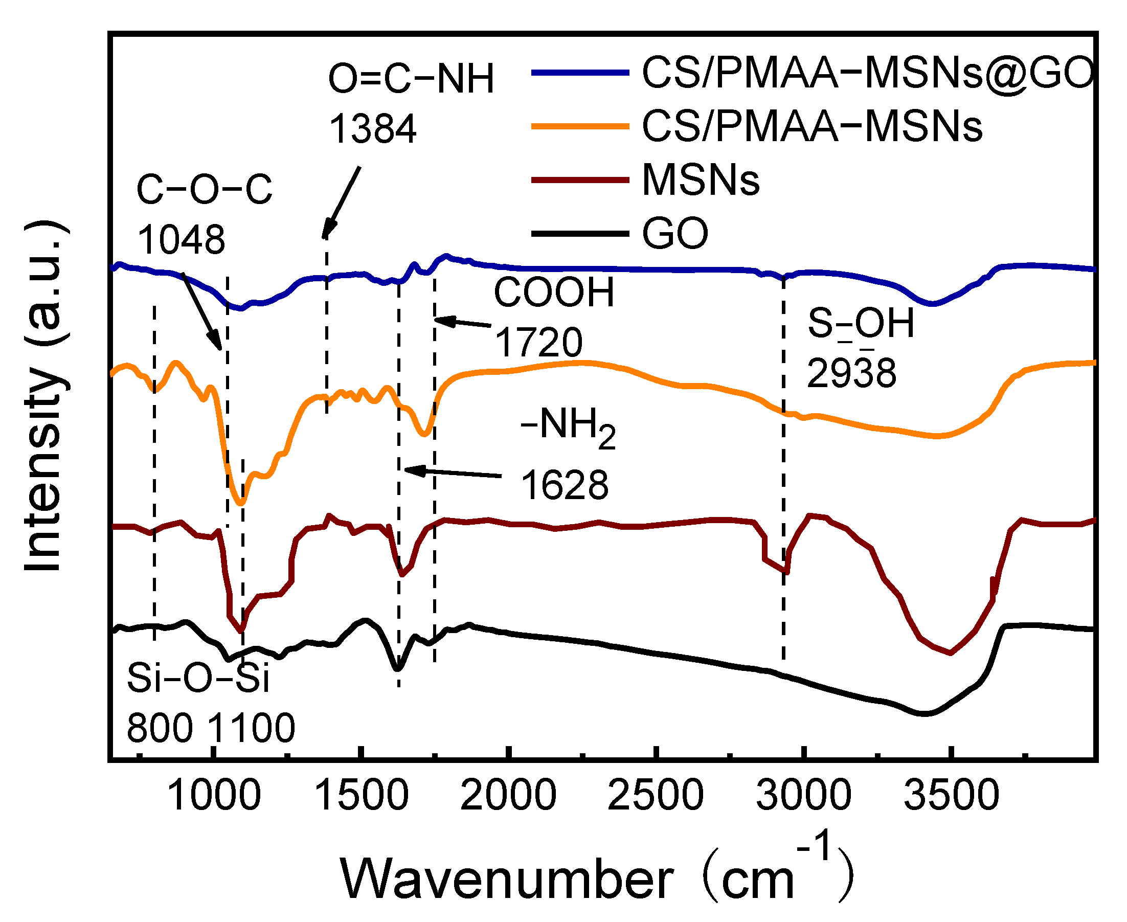
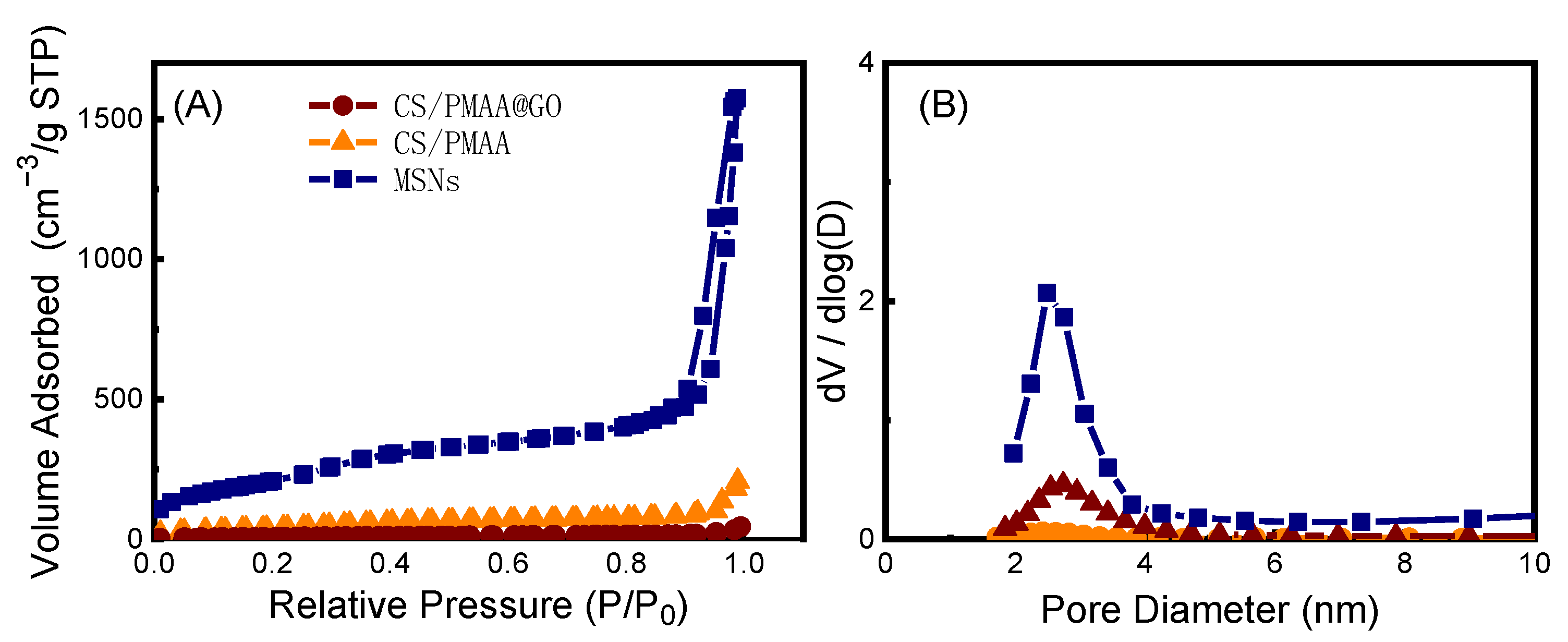
3.1. Characterization of CS/PMAA-MSNs@GO

The TEM micrographs (Figure 5C) revealed that the diameters of the MSNs were approximately 70 nm. Due to the successful deposition of CS/PMAA molecules onto the surface of the MSN spherical shell, the TEM (Figure 5F) indicated that there was a thin layer of polymer on the surface of CS/PMAA-coated MSN nanoparticles [20]. Therefore, it can be demonstrated that the polymer-modified MSNs were successfully obtained by the in situ polymerization method.
Figure 6 shows the FT-IR spectra of the GO, MSNs, CS/PMAA-MSNs, and CS/PMAA-MSNs@GO. In the MSNs spectrum, the band at 2938 cm−1 is the Si-OH bending vibration of the MSNs surface, and the bands at 800 and 1100 cm−1 are characteristic of the MSNs peak [16]. Compared with the MSNs spectrum, the -NH2 bending vibration peak at 1628 cm−1 appeared in the CS/PMAA-MSNs spectrum, indicating CS grafting. The peaks at 1048 cm−1 in the CS/PMAA-MSNs@GO spectra were significantly weakened; it can be seen that the reaction between GO and CS/PMAA-MSNs was chemical bonding rather than simple physical adsorption.
In addition, the TG analyses (Figure 7) were performed to investigate the loading capacity of the corrosion inhibitor. Before the start of the test, the TA-loaded samples were washed sufficiently to prevent the physical mixing from interfering with the experiment. There was some mass loss at 30~100 °C due to the evaporation of physisorbed water. The properties of the graphene oxide and tannic acid determined their thermogravimetric-analysis curves. Specifically, tannic acid is an organic substance rich in carbon, hydrogen, and oxygen, which causes it to be decomposed by combustion at 600 °C. Graphene oxide is also rich in oxygen-containing functional groups and is easily oxidized and decomposed at 600 °C. Therefore, the mass losses of the TA and GO were 100% at 600 °C. However, the thermogravimetric curve of the PMAA-MSNs@GO at 600~800 °C is different from that of the GO and TA, which is because the CS/PMAA-MSNs@GO was grafted with high-temperature-resistant MSNs. By comparing the mass losses of the CS/PMAA-MSNs@GO and CS/PMAA-MSNs@GO loading TA (Figure 7), which were 89.32% and 93.49% respectively, it can be concluded that the loading ratio of the tannic acid in the CS/PMAA-MSNs@GO was 4.14% [17].

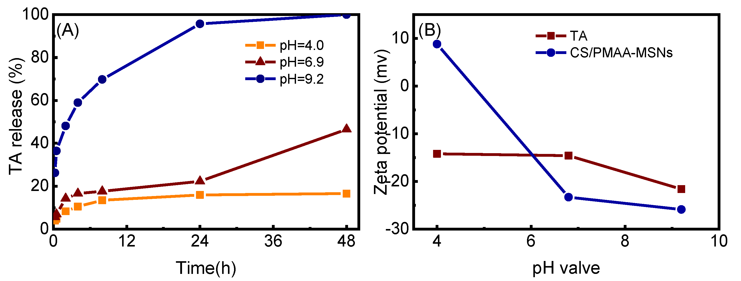
3.2. Analysis of Controlled-Release Behavior

It must be mentioned that the special mesoporous structure is the premise of controllable release. Therefore, a desorption/adsorption experiment of N2, Brunauer–Emmett–Teller (BET), and Barrett-Joyner-Halenda (BJH) was carried out on the sample to analyze its mesoporous characteristics (Figure 8 and Table 1). It can be seen that the MSNs prepared by the modified Stöber method had obvious mesoporous properties (Figure 8). According to the pore sizes of the porous materials, three types of porous materials were defined: porous materials with pore sizes below 2 nm were defined as microporous materials; those between 2 and 50 nm were defined as mesoporous materials; and porous materials greater than 50 nm were defined as macroporous materials. The average pore size of the CS/PMAA-MSNs@GO was 3.39 nm (Table 1).
To demonstrate that CS/PMAA-MSNs@GO has the property of releasing TA under alkaline conditions, TA-loaded CS/PMAA-MSNs@GO were re-dispersed in different pH environments by configuring standard buffer solutions. At appropriate time intervals, 2 mL of supernatant were collected by centrifugation while adding 2 mL of fresh special buffer solution to keep the release-medium volume constant. Three pH values, of 4.0, 6.9, and 9.2, were used to simulate different corrosive environments. The amount of TA in the release medium was measured by UV at a wavelength of 311 nm. The release amount was roughly calculated according to the formula.
TA   release   content   ( % ) = Absorbance   of   311   nm   in   different   time Maximum   absorbance   of   311   nm × 100 %
The release profiles of TA from CS/PMAA-MSNs@GO were determined at pH values of 4.0, 6.9, and 9.2 for 48 h at room temperature. Figure 9A and Figure S1 demonstrate that the TA-release content was pH-dependent and increased with the pH. According to previous studies, the release of TA from CS/PMAA-MSNs is often determined by the electrostatic interaction between tannins and CS/PMAA-MSNs [21]. Specifically, because the zeta potential of TA and CS/PMAA-MSNs was negatively charged at pH values of 4.0 (Figure 9B), it was easy for the loaded TA to be released out of the CS/PMAA-MSNs when there was strong repulsion between them [14].

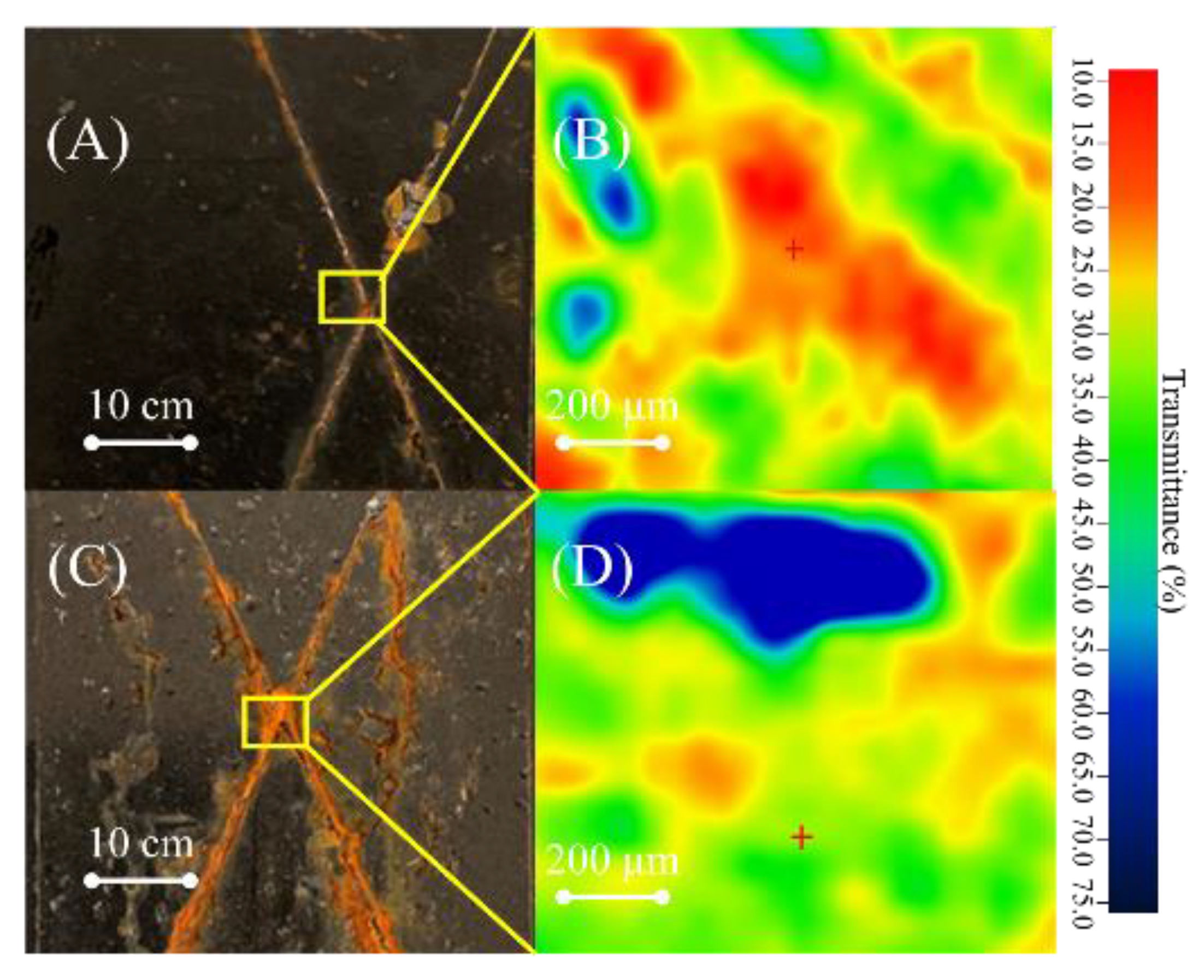
3.3. Smart Self-Healing Performance of CS/PMAA-MSNs@GO/TA Coating

According to the research, the corrosion mechanism of steel is as follows:
Fe → Fe2+ + 2e
8FeOOH + Fe2+ + 2e → 3Fe3O4 + 4H2O
3Fe3O4 + 3/4O2 + 9/2H2O → 9FeOOH
Steel corrosion can be divided into three stages. These three stages form a certain cycle, failing steel [22].
1.
Iron loses electrons and is oxidized to form iron oxyhydroxide (FeOOH), which is difficult to avoid;
2.
Iron oxyhydroxide can be further oxidized to form rust (Fe3O4);
3.
The rust is loose and porous, and it is further oxidized to form iron oxyhydroxide when it enters into contact with the corrosive medium.
Therefore, for stage 2, corrosion products were converted with corrosion inhibitors, interrupting this process, thereby protecting the steel substrate. The specific corrosion-inhibition mechanism is as follows [23]:
FeOOH + 2 TH 3 + 3 H + + e       Fe TH 3 2 + 2 H 2 O 2 Fe ( TH 3 ) 2 + 2 TH 3 + 2 H + + O 2     2 Fe ( TH 3 ) 3 + H 2 O
The difference between the corrosion-inhibition product (Fe(TH3)3) and the loose rust is that it behaves as a dense passivation layer, which can block the penetration of corrosion products. The optical micrograph in Figure 10A shows much more minor rust for the CS/PMAA-MSNs@GO loading TA coating after 480 h of salt spray compared to Figure 10B. The absorption peak of ferric tannate is 1705 cm−1. Therefore, the FT-IR microscope test showed a transmittance distribution with an absorption peak at 1705 cm−1. There is a red crevice on the FT-IR map, indicating that the corrosion-inhibition products in the crevice were ferric tannate. Thus, we can spectroscopically prove that tannic acid flowed from the coating, formed a corrosion inhibition film, and was responsible for the successful inhibition of the scratched crevice to inhibit corrosion [24].

3.4. EIS Performance of CS/PMAA-MSNs@GO/TA Coating

The impedance value at a low frequency (0.01 Hz) is an important reference for evaluating the corrosion resistance of coatings. According to recent studies, the impedance modulus value (|Z|0.01 Hz) at low frequencies is generally higher than 108 Ω∙cm2, which indicates that the coating has sufficiently good corrosion resistance to protect the metal substrate. The impedance-modulus value at high frequencies is related to the capacitive performance of the coating, while the impedance-modulus value at medium and low frequencies corresponds to the corrosion response of the metal substrate [25,26]. In addition to |Z|0.01 Hz, which can reflect the corrosion resistance of the coating, there is a parameter in the frequency–phase relationship diagram on the Bode diagram that is closely related to the microscopic delamination area and the residual porosity of the coating, which is used to evaluate the coating. The state of the steel interface is an important parameter, which is usually represented by the corresponding response frequency at 45°, also known as the breakpoint frequency (FB). The higher the FB, the worse the anticorrosion effect [27,28].
The impedance modulus value (|Z|0.01 Hz) and breakpoint frequency (FB) of pure EP and GO/EP coatings, immersed for 48 h, shown in Figure 11 and Table 2, were lower than the effective impedance value (108 Ω·cm2), indicating that the EP coating had poor corrosion resistance, and that adding unmodified filler GO had little effect on the enhancement of the corrosion resistance. For the CS/PMAA-MSNs@GO/TA/EP, immersed for 48 h, the |Z|0.01Hz and FB were 6.20 × 10⁹ Ω∙cm2 and 6.76 × 10⁻¹ Hz, indicating that they had excellent corrosion resistance.
The potentiodynamic-polarization curve can be used to further study the anti-corrosion effect of the nanofillers in the coating. The corresponding polarization curve of the coating after immersion in 3.5 wt% NaCl solution for 960 h is shown in Figure 12. The corrosion-potential information was obtained by extrapolating the straight-line parts of the cathodic and anodic polarization curves [29,30]. On one hand, it can be seen from Figure 12 and Table 3 that the corrosion potential Ecorr of the pure EP and the 2 wt% GO/EP coatings were both negative, and that the corrosion current Icorr was also large, indicating that there was a certain number of tiny pores in the EP and GO/EP coating. As a result, neither could resist the penetration of the corrosive media for a long time. On the other hand, the CS/PMAA-MSNs@GO/TA/EP combined with the lamellar labyrinth effect of the GO and the corrosion inhibition of the modified MSNs, with a lower corrosion current. Specifically, the 2 wt% CS/PMAA-MSNs @GO/TAs Ecorr was 979 mV higher and the Icorr was five orders of magnitude lower, demonstrating that the steel substrate is effectively protected over a long period of time. However, it must be mentioned that 5 wt% CS/PMAA-MSNs @GO/TA’s Ecorr had a more negative Ecorr and larger Icorr than the 2 wt% CS/PMAA-MSNs @GO/TA, indicating that adding excessive filler affects the effect of the filler dispersion during coating, causes agglomeration, and affects the corrosion potential and corrosion current.
Additionally, other properties, such as stability, impact resistance, fracture sections, friction coefficient, and salt-spray corrosion, are shown in Figures S1–S7.

4. Conclusions

By modifying mesoporous silica nanoparticles with the in situ polymerization method and further grafting graphene oxide, a novel type of layered-nanosphere structure was prepared. The BET and TG test results showed that the structure had a high specific surface area, which can prolong the penetration path of the corrosive medium, and the mesoporous structure can be loaded with corrosion inhibitors. Unlike the general mesoporous structure, after modification with a highly pH-sensitive polymer, the results of the UV-Vis spectrophotometer and the FT-IR mapping tests showed that under alkaline conditions, the structure can prevent UV-induced photodegradation and accelerate the release rate of the inhibitor-tannin from the mesoporous structure, according to the local and induced pH increase during corrosion, and then form iron compound (iron tannate) in the corrosion area of the coating iron, thereby mitigating corrosion. The results of the electrochemical impedance and polarization curves show that the coating can greatly enhance the effect of metal protection. Therefore, this article provides an approach to the design of heavy-duty anti-corrosion coatings and nano-smart coatings.

Supplementary Materials

The following supporting information can be downloaded at: https://www.mdpi.com/article/10.3390/coatings12111749/s1, Figure S1: (a–c) UV spectra of CS/PMAA-MSNs@GO (1, 1/5, and 1/10) loaded with tannic acid with different concentrations obtained after the designed experiment under different pH environments; (d) CS/PMAA-MSNs is the kinetic curve of tannin release; Figure S2: Stability of GO, MSNs, CS/PMAA-MSNs, and CS/PMAA-MSNs@GO in EP; Figure S3: Coating impact resistance test results of GO, MSNs, CS/PMAA-MSNs, and CS/PMAA-MSNs@GO; Figure S4: Fracture sections for different coatings: (a,e) EP, (b) CS/PMAA-MSNs/EP, (c) GO/EP, and (d,f) BN@F-SiC/EP; Figure S5: (a) Variation trend of the friction coefficient and (b) average coefficient of friction; Figure S6: Profilometry images of wear traces: (a) EP; (b) GO/EP; (c) CS/PMAA-MSNs/EP; (d) CS/PMAA-MSNs@GO/EP; Figure S7: Salt spray corrosion diagram for the samples: (a) original state of the samples and (b) the state of the samples after 480 h of salt spray corrosion.

Author Contributions

Conceptualization, validation, resources, data management, Z.L.; formal analysis, H.Y.; methodology, Z.Z.; writing—review and editing, B.Z. and W.J.; supervision, Z.M. All authors have read and agreed to the published version of the manuscript.

Funding

This work was supported by the Excellent Youth Project of Hunan Education Department (No. 18B080).

Institutional Review Board Statement

Not applicable.

Informed Consent Statement

Not applicable.

Data Availability Statement

All the data are available within the manuscript.

Acknowledgments

This work was supported by Excellent Youth Project of Hunan Education Department (No. 18B080), Natural Science Foundation of Hunan Province (No. 2021JJ30643), The authors would like to thank Peng Xu from Shiyanjia Lab (www.shiyanjia.com, accessed on 19 May 2022) for the FT-IR mapping of the crevice analysis.

Conflicts of Interest

The authors declare no conflict of interest.

References

  1. Sun, J.; Xiao, X.; Meng, G.; Gu, L. Mussel-Inspired Hydrophobic Modification of Boron Nitride Nanosheets to Enhance the Dispersion and Anticorrosive Performance in Polymeric Coatings. Prog. Org. Coat. 2022, 170, 106986. [Google Scholar] [CrossRef]
  2. Lei, Y.; Jiang, Z.N.; Zeng, X.Q.; Li, Y.Y.; Wang, X.; Liu, H.F.; Zhang, G.A. Preparation of ZIF-67@DTMS NPs/Epoxy Composite Coating and Its Anti-Corrosion Performance for Q235 Carbon Steel in 3.5 Wt% NaCl Solution. Colloids Surf. A Physicochem. Eng. Asp. 2022, 656, 130370. [Google Scholar] [CrossRef]
  3. Cao, Y.; He, J.; Wu, J.; Wang, X.; Lu, W.; Lin, J.; Xu, Y.; Chen, G.; Zeng, B.; Dai, L. A Smart Anticorrosive Epoxy Coating Based on Environmental-Stimuli-Responsive Copolymer Assemblies for Controlled Release of Corrosion Inhibitors. Macromol. Mater. Eng. 2022, 307, 2100983. [Google Scholar] [CrossRef]
  4. Zheng, Z.; Li, H.; Li, F.; Zheng, L.; Yin, S.; Wang, X.; Yan, Y. An Efficient PDA/Al2O3 Nanosheets Reinforced Ultra-Thin ZrO2 Coating with Attractive Anti-Corrosion and Deuterium Resistance Property. Chem. Eng. J. 2022, 450, 138307. [Google Scholar] [CrossRef]
  5. Peng, T.; Xiao, R.; Rong, Z.; Liu, H.; Hu, Q.; Wang, S.; Li, X.; Zhang, J. Polymer Nanocomposite-Based Coatings for Corrosion Protection. Chem. Asian J. 2020, 15, 3915–3941. [Google Scholar] [CrossRef] [PubMed]
  6. Zhang, M.; Xu, F.; Lin, D.; Peng, J.; Zhu, Y.; Wang, H. A Smart Anti-Corrosion Coating Based on Triple Functional Fillers. Chem. Eng. J. 2022, 446, 137078. [Google Scholar] [CrossRef]
  7. Ghaderi, M.; SaadatAbadi, A.R.; Mahdavian, M.; Haddadi, S.A. PH-Sensitive Polydopamine–La (III) Complex Decorated on Carbon Nanofiber toward On-Demand Release Functioning of Epoxy Anti-Corrosion Coating. Langmuir 2022, 38, 11707–11723. [Google Scholar] [CrossRef]
  8. Zhao, X.; Jiang, D.; Ma, L.; Zeng, X.; Li, Z.; Huang, G. Special Issue: Corrosion Effects and Smart Coatings of Corrosion Protection. Coatings 2022, 12, 1378. [Google Scholar] [CrossRef]
  9. Castaldo, R.; de Luna, M.S.; Siviello, C.; Gentile, G.; Lavorgna, M.; Amendola, E.; Cocca, M. On the Acid-Responsive Release of Benzotriazole from Engineered Mesoporous Silica Nanoparticles for Corrosion Protection of Metal Surfaces. J. Cult. Herit. 2020, 44, 317–324. [Google Scholar] [CrossRef]
  10. Farooq, S.A.; Raina, A.; Mohan, S.; Arvind Singh, R.; Jayalakshmi, S.; Irfan Ul Haq, M. Nanostructured Coatings: Review on Processing Techniques, Corrosion Behaviour and Tribological Performance. Nanomaterials 2022, 12, 1323. [Google Scholar] [CrossRef]
  11. Olivieri, F.; Castaldo, R.; Cocca, M.; Gentile, G.; Lavorgna, M. Mesoporous Silica Nanoparticles as Carriers of Active Agents for Smart Anticorrosive Organic Coatings: A Critical Review. Nanoscale 2021, 13, 9091–9111. [Google Scholar] [CrossRef] [PubMed]
  12. Xu, J.; Gao, F.; Wang, H.; Dai, R.; Dong, S.; Wang, H. Organic/Inorganic Hybrid Waterborne Polyurethane Coatings with Self-Healing Properties for Anticorrosion Application. Prog. Org. Coat. 2022, 174, 107244. [Google Scholar] [CrossRef]
  13. Liu, T.; Zhang, D.; Ma, L.; Huang, Y.; Hao, X.; Terryn, H.; Mol, A.; Li, X. Smart Protective Coatings with Self-sensing and Active Corrosion Protection Dual Functionality from PH-Sensitive Calcium Carbonate Microcontainers. Corros. Sci. 2022, 200, 110254. [Google Scholar] [CrossRef]
  14. Sun, X.; Ma, C.; Ma, F.; Wang, T.; Feng, C.; Wang, W. A Novel Coating with SiO2 Anchored on MXene Loading Tannic Acid for Self-Healing Anticorrosive Performance. J. Alloys Compd. 2022, 928, 167202. [Google Scholar] [CrossRef]
  15. Santos, L.R.L.; Leal, D.A.; Marino, C.E.B.; Riegel-Vidotti, I.C. PH-Triggered Release of Tannic Acid as Green Corrosion Inhibitor for Carbon Steel. Mater. Today Commun. 2022, 2022, 103730. [Google Scholar] [CrossRef]
  16. Zhang, Z.; Yuan, H.; Qi, F.; Zhao, N.; Zhang, B.; Ouyang, X. Functionalized Modified BN@F-SiC Particle-Incorporating Epoxy: An Effective Hydrophobic Antiwear and Anticorrosion Coating Material. Ind. Eng. Chem. Res. 2021, 60, 8430–8441. [Google Scholar] [CrossRef]
  17. Wang, W.; Wang, H.; Zhao, J.; Wang, X.; Xiong, C.; Song, L.; Ding, R.; Han, P.; Li, W. Self-Healing Performance and Corrosion Resistance of Graphene Oxide–Mesoporous Silicon Layer–Nanosphere Structure Coating under Marine Alternating Hydrostatic Pressure. Chem. Eng. J. 2019, 361, 792–804. [Google Scholar] [CrossRef]
  18. Tang, H.; Guo, J.; Sun, Y.; Chang, B.; Ren, Q.; Yang, W. Facile Synthesis of PH Sensitive Polymer-Coated Mesoporous Silica Nanoparticles and Their Application in Drug Delivery. Int. J. Pharm. 2011, 421, 388–396. [Google Scholar] [CrossRef]
  19. Ma, Y.; Di, H.; Yu, Z.; Liang, L.; Lv, L.; Pan, Y.; Zhang, Y.; Yin, D. Fabrication of Silica-Decorated Graphene Oxide Nanohybrids and the Properties of Composite Epoxy Coatings Research. Appl. Surf. Sci. 2016, 360, 936–945. [Google Scholar] [CrossRef]
  20. Cai, H.; Wang, P.; Zhang, D. Smart Anticorrosion Coating Based on Stimuli-Responsive Micro/Nanocontainer: A Review. J. Oceanol. Limnol. 2020, 38, 1045–1063. [Google Scholar] [CrossRef]
  21. Maia, F.; Tedim, J.; Lisenkov, A.D.; Salak, A.N.; Zheludkevich, M.L.; Ferreira, M.G.S. Silica Nanocontainers for Active Corrosion Protection. Nanoscale 2012, 4, 1287–1298. [Google Scholar] [CrossRef] [PubMed]
  22. Cleary, H.J. On the Mechanism of the Corrosion of Steel in Saline Water. JOM 1970, 22, 39–46. [Google Scholar] [CrossRef]
  23. Zhao, B.; Han, W.; Zhang, W.; Shi, B. Corrosion Inhibition Performance of Tannins for Mild Steel in Hydrochloric Acid Solution. Res. Chem. Intermed. 2018, 44, 407–423. [Google Scholar] [CrossRef]
  24. Qian, B.; Hou, B.; Zheng, M. The Inhibition Effect of Tannic Acid on Mild Steel Corrosion in Seawater Wet/Dry Cyclic Conditions. Corros. Sci. 2013, 72, 1–9. [Google Scholar] [CrossRef]
  25. Zhao, J.; Xie, X.; Zhang, C. Effect of the Graphene Oxide Additive on the Corrosion Resistance of the Plasma Electrolytic Oxidation Coating of the AZ31 Magnesium Alloy. Corros. Sci. 2017, 114, 146–155. [Google Scholar] [CrossRef]
  26. Wemmert, S.; Ketter, R.; Rahnenführer, J.; Beerenwinkel, N.; Strowitzki, M.; Feiden, W.; Hartmann, C.; Lengauer, T.; Stockhammer, F.; Zang, K.D.; et al. Patients with High-Grade Gliomas Harboring Deletions of Chromosomes 9p and 10q Benefit from Temozolomide Treatment. Neoplasia 2005, 7, 883–893. [Google Scholar] [CrossRef] [Green Version]
  27. Cui, M.; Ren, S.; Pu, J.; Wang, Y.; Zhao, H.; Wang, L. Poly(o-Phenylenediamine) Modified Graphene toward the Reinforcement in Corrosion Protection of Epoxy Coatings. Corros. Sci. 2019, 159, 108131. [Google Scholar] [CrossRef]
  28. Zhao, X.; Wang, J.; Wang, Y.; Kong, T.; Zhong, L.; Zhang, W. Analysis of Deterioration Process of Organic Protective Coating Using EIS Assisted by SOM Network. Electrochem. Commun. 2007, 9, 1394–1399. [Google Scholar] [CrossRef]
  29. Xiong, L.; Liu, J.; Yu, M.; Li, S. Improving the Corrosion Protection Properties of PVB Coating by Using Salicylaldehyde@ZIF-8/Graphene Oxide Two-Dimensional Nanocomposites. Corros. Sci. 2019, 146, 70–79. [Google Scholar] [CrossRef]
  30. Beving, D.E.; McDonnell, A.M.P.; Yang, W.; Yan, Y. Corrosion Resistant High-Silica-Zeolite MFI Coating. J. Electrochem. Soc. 2006, 153, B325. [Google Scholar] [CrossRef]
Figure 1. Schematic route of the smart anticorrosive epoxy coating based on graphene oxide/functional mesoporous silica nanoparticles.
Coatings 12 01749 g001
Figure 2. Synthesis mechanism of mesoporous silica nanoparticles (MSNs).
Coatings 12 01749 g002
Figure 3. Synthesis mechanism of pH-responsive polymer shell chitosan/poly (methacrylic acid) (CS-PMAA) coating on mesoporous silica nanoparticles (CS/PMAA-MSNs).
Coatings 12 01749 g003
Figure 4. Synthesis mechanism of graphene oxide (GO) grafted functional silica nanoparticles loaded with tannic acid.
Coatings 12 01749 g004
Figure 5. (A) SEM images of MSNs, (B) CS/PMAA-MSNs, (D) GO, and (E) CS/PMAA-MSNs@GO; TEM images of (C) MSNs and (F) CS/PMAA-MSNs.
Coatings 12 01749 g005
Figure 6. FT−IR spectra of GO, MSNs, and CS/PMAA-MSNs.
Coatings 12 01749 g006
Figure 7. GO, TA, MSNs, MSN loading TA, CS/PAMAA-MSNs@GO, and CS/PMAA-MSNs@GO loading TA under air atmosphere heated from 30 to 800 °C.
Coatings 12 01749 g007
Figure 8. (A) N2−adsorption−desorption isotherms and (B) pore-size distributions of MSNs, CS/PMAA-MSNs, and CS/PMAA-MSNs@Go.
Coatings 12 01749 g008
Figure 9. (A) Release profiles of TA from CS/PMAA-MSNs@GO composite microspheres at pH values of 4.0, 6.9, and 9.2; (B) zeta potential of TA and CS/PMAA-MSNs@GO at different pH.
Coatings 12 01749 g009
Figure 10. (A) Optical micrograph of the scratched crevice coating after 480 h of the salt spray of CS/PMAA-MSNs@GO loading TA coating and (B) FT-IR mapping test by the FT-IR microscope; (C) optical micrograph of CS/PMAA-MSNs@GO coating without TA and (D) FT-IR mapping.
Coatings 12 01749 g010
Figure 11. (A,B) Equivalent circuit model for fitting experimental impedance data; (C) Bode diagrams of EP, GO/EP, CS/PMAA-MSNs@GO/TA/EP immersed for 8 h and (D) 48 h.
Coatings 12 01749 g011
Figure 12. Tafel diagram of different coatings soaked in 3.5% NaCl immersed for 960 h.
Coatings 12 01749 g012
Table 1. BET and BJH parameters of MSNs, CS/PMAA-MSNs, and CS/PMAA-MSNs @GO.
SubstratesBET—Specific Surface Area (m2/g)BJH—Average Pore Size (nm)Pore Volume (cm3/g)
MSNs762.598.992.44
CS/PMAA-MSNs333.744.390.17
CS/PMAA-MSNs@Go158.223.390.03
Table 2. The impedance values at 0.01 Hz, and breakpoint frequencies of EP, GO/EP, and CS/PMAA-MSNs@GO/TA/EP coatings.
SampleTime (h)|Z|0.01 Hz(Ω·cm2)Breakpoint Frequency (Hz)
EP8 h1.86 × 1062.39 × 101
48 h1.45 × 1041.00 × 104
GO/EP8 h3.09 × 1083.13 × 101
48 h4.55 × 1054.22 × 104
CS/PMAA-MSNs@GO/TA/EP8 h8.29 × 10103.17 × 10−1
48 h6.20 × 1096.76 × 10−1
Table 3. Corrosion potential (Ecorr), corrosion−current density (Icorr) of different samples after 960 h of immersion in 3.5 wt% NaCl aqueous solution.
Sample NameEcorr (V vs. SCE)Icorr (A/cm2)βa (V/dec)−βc (V/dec)
EP−1.1283.232 × 10−70.1340.081
GO−0.5723.820 × 10−90.6183.082
1% CS/PMAA-MSNs@GO/TA−0.7145.990 × 10−120.0690.421
2% CS/PMAA-MSNs@GO/TA−0.1491.740 × 10−120.6290.118
3% CS/PMAA-MSNs@GO/TA−0.1607.230 × 10−111.291−1.068
4% CS/PMAA-MSNs@GO/TA−0.1911.030 × 10−110.781−0.139
5% CS/PMAA-MSNs@GO/TA−0.1834.510 × 10−91.2381.442
Publisher’s Note: MDPI stays neutral with regard to jurisdictional claims in published maps and institutional affiliations.

