Article

Microstructure and Properties of TiAl Composite Coatings Prepared by Laser Cladding under Multi-Phase β0/CoAl2Ti Phase Strengthening

School of Materials Science and Engineering, Shandong University of Science and Technology, Qingdao 266590, China
*
Authors to whom correspondence should be addressed.
Coatings 2022, 12(10), 1593; https://doi.org/10.3390/coatings12101593
Submission received: 21 September 2022 / Revised: 11 October 2022 / Accepted: 18 October 2022 / Published: 20 October 2022

Abstract

:
Ceramic-reinforced TiAl matrix composite coatings are fabricated by laser cladding on Ti-6Al-4V (TC4) surfaces. The present work focuses on matching of the ceramic phase with the TiAl matrix to achieve a strength–toughness matching through the multi-scale multi-phase structure. The results indicated that the structure of composites coatings, including γ, α2, β0, CoAl2Ti, and TiC phases, significantly improved the properties of the composite coatings. The TiAl composite coating reached a maximum hardness of 741.17 Hv0.2, and the 10 at% tungsten carbide (10 WC) coating has the lowest wear volume of 8.8 × 107 μm3, the friction performance was approximate five times that of TC4. Detailed explanation of the friction properties and friction mechanism of the composite coating based on crystallographic orientation relationships and nanoindentation results. The study found that strength–toughness matching is important for the improvement of friction performance. Based on the TiAl alloy generated in the non-equilibrium solidification state in this paper, the solidification process and microstructure evolution are analyzed in detail.

Graphical Abstract

1. Introduction

Titanium alloys, particularly Ti-6Al-4V (TC4), have shown great for use in the aerospace, automotive, and marine industrial fields due to their low density, high specific strength, and good corrosion resistance [1,2,3,4]. However, the high metal activity, low hardness, and low resistance to shearing of the TC4 alloys, which contributes to the inferior tribological performance, become principal obstacles that limit their application [3]. Particularly in engineering applications, metallic motion components such as valves, pumps, and hydraulic devices must withstand abrasion from friction pairs. Therefore, there is an urgent demand for ways to improve the wear of TC4. A literature review [5] revealed surface modification as an efficient and low-cost approach to improving the performance of TC4. However, it is difficult to find a coating material with excellent friction and suitable for the TC4 service environment.
TiAl alloys are a class of lightweight structural material that can provide superior strength at high temperatures with high specific yield strength while offering increased wear resistance and corrosion resistance similar to that of TC4 [6,7]. These advantages in the corrosion and tribological behavior of TiAl alloys are requisite factors for their uses in engineering applications. Thus, the TiAl alloy was used as the surface protection layer of TC4 in the experiments described herein.
Pure TiAl alloys as a surface protection layer for TC4 are lacking due to their low hardness and poor tribological properties. Long-term studies [8] have shown that the fabricated ceramic–metal composites are an important aspect of the design strategy for wear-resistant materials, with TiAl ceramic–metal composites having attracted increasing attention. He et al. [9] studied the preparation of the TiAl/TiC composite coating on the Ti–48Al–2Cr–2Nb surface by laser cladding and found the wear resistance of the coatings was improved. As TiAl alloys are inherently brittle at room temperature, it is difficult to further improve their wear resistance. However, only improving their hardness to improve friction performance is not reliable since their strength and toughness function in tandem. Lee et al. [10] manufactured a BN/Si3N4 nanocomposite material to simultaneously enhance the toughness and wear resistance of the coating. While it is important to improve the toughness of the TiAl alloy, this is difficult to achieve. Bai et al. [11] presented multi-scale structural coating, where different phases, different morphologies, different scales, in synergy, coupling to improve the hardness wear resistance and toughness of the coating. Thus, multi-scale hybrid reinforcement was used herein to improve the toughness and friction properties of the TiAl alloy.
In recent decades, several preparation methods were revealed to improve the properties of the TiAl alloy, such as vacuum melting [12], powder metallurgy [13], spark plasma sintering [14], hot isostatic pressing [15], and laser cladding. In recent years, laser cladding experienced rapid development as a surface treatment method with the advantages of its low cost, high efficiency, fast cooling speed, and low dilution rate. Laser cladding has been widely used in the study of wear and corrosion resistance in coatings. Maliutina et al. [16] produced a protective Ti–48Al–2Cr–2Nb coating on titanium alloy surfaces by laser cladding. The results found that the oxidation performance of titanium alloy had been noticeably improved. TiAl composite coatings have been successfully manufactured by laser cladding. However, few have fabricated TiAl composite coatings on TC4 surfaces to study the wear resistance properties of TiAl-based alloys. Therefore, in this paper, we fabricated a TiAl-based composite coating on the TC4 surface by laser cladding and studied the friction properties of the TiAl alloy.
In our work, ceramic–metal multi-scale TiAl composite coatings are prepared from Ti–48Al–2Cr–2Nb with excellent casting performance to ensure the formability of the laser cladding coating. The advantages of the coatings we studied include strong adhesion to the substrate, controlled thickness of the prepared coating, simplicity of preparation and low cost. The thickness of the coatings prepared in this experiment can be regulated and is more suitable for industrial applications. This paper details the microstructure and microstructural evolution in the non-equilibrium solidification state of TiAl alloys. We also studied the effect of β0 phase on friction properties. Meanwhile, in the study, coupling of the ceramic phase with the TiAl matrix was carried out to achieve a strength–toughness match through the multi-scale multi-phase structure. We also detail how the ceramic–metal multi-scale TiAl composite coatings enhance wear resistance and the wear mechanism of TiAl alloys. These studies benefit guidance on improving the wear resistance of TiAl alloys while providing novel insight for the preparation of TC4 protective coatings.

2. Materials and Methods

2.1. Preparation of Materials

The actual alloy powder ratios are shown in Table 1. The amount of WC added for the 0–15 WC powders was, respectively 0, 5, 10, and 15 at%. The purity and size of the alloy powders were as follows: Ti (≥99.5 wt%, 40–50 μm), Al (≥99.5 wt%, 40–50 μm), Nb (≥99.5 wt%, 40–50 μm), Cr (≥99.5 wt%, 40–50 μm). The composition and morphology of the WC powders are shown in Figure 1. WC powder is hollow and spherical, can easily decompose during laser cladding, and contains 2% Co. The mixed alloy powder was milled in a three-dimensional (3D) mixer for 12 h and then dried in a drying oven for 6 h at 120 °C.
This experiment uses a laser system with a rated power of 2000 W, a maximum power density of 667 KW/mm, and a wavelength of 980 nm. The mixed powder is laid flat on the surface of TC4, the thickness of the powder is 2 mm, and the width is 5 mm, with the laser system single-track operation sweeping through the already-laid mixed powder. Before using the TC4, the surface was polished with 400#, 1000#, and 1500# sandpaper and surface impurities were removed with alcohol. The purpose of this step is to ensure a clean bond between the coating and the substrate and to guarantee the quality of the laser cladding. Prior to laser cladding, the surface of TC4 is covered with a layer of oxide film, oil and impurities, which affect the formability of the laser cladding and the bonding of the substrate to the coating. Alcohol is perfectly adequate to achieve the desired effect and has been used by others who have conducted similar experiments [17,18]. Prior to the cladding experiment, the uncoated area was preheated with a laser to eliminate residual stress and avoid cracks. The composite coating was prepared using 90% of the rated power and a scanning rate of 5 mm/s in a chamber filled with Ar gas. Figure 2 shows SEM of the prepared sample coating and TC4 cross-section, which shows that each sample forms a defect-free metallurgical bond with TC4.

2.2. Observation and Analysis of Coatings

The phase composition of the analyzed coatings was detected using an X-ray diffractometer of type D/Max 2500 PC with a radiation source of Cu Ka (k = 0.15405 nm). The prepared coating samples were swept from 10 to 90° degrees at a rate of 4°/min. The phase composition of the coating was determined using Jade software and standard PDF cards. The microstructure of the coating was characterized by field emission high-resolution scanning electron microscopy (SEM, FEI Nova NANO-SEM 450, Hillsboro, OR, USA), and the composition was analyzed by its equipped EDS energy spectrometer. The microstructure was observed after etching with Kroll solution. Further microstructure, phase composition, and composition analysis by transmission electron microscopy (Thermo Fisher Scientific Talos F200X G2 TEM, Waltham, MA, USA). The transmitted sample was ground to 50 μm before ion thinning.

2.3. Properties Test

The Vickers micro-hardness was measured at a loading of 200 g with a dwell time of 15 s. A hardness point was created every 100 microns on the side of each coating from the top surface to the substrate. Nanoindentation tests were performed by Bruker Hysitron TI980 (Bruker, Berlin, Germany). Nanoindentation tests were carried out on different phases of the coating, 3 times for each phase, and finally the type of phase was determined by SEM-EDS. Dry sliding reciprocating friction test was conducted on a type Rect MFT-5000, USA testing machine, with Al2O3 ball selected for the counterpart material, load 30 N, and time 30 min. Al2O3 was used as the counterpart material mainly because it does not react with the composite coating. The mode of friction was reciprocating friction, with a stroke of 5 mm and a frequency of 1 Hz. Friction coefficient was automatically generated on the computer. A 3D morphometer (Bruker Contour GT-K1, Berlin, Germany) measured the wear volume and morphology. Each friction sample was tested three times and averaged. The morphology of the worn surfaces and wear debris was also evaluated by SEM-EDS.

3. Results and Discussion

3.1. Phase Analysis

Figure 3 shows the XRD patterns of coatings with different WC contents. The phase composition of the coating is only α2 (Ti3Al) and γ (TiAl) phases when no WC is added, but many TiC and β0 phases appear when WC is added (Figure 3a) [19]. With the addition of WC, the diffraction peaks of β0 phase gradually becomes high and Ti3Al phase becomes low. This indicates that the content of β0 phase gradually increased and Ti3Al phase decreased. Figure 3b shows a local enlargement of 36–45°, TiAl, Ti3Al, and β0 all shift to the right as the added amount of WC increases presumably because W, Nb, and Cr are dissolved solids in these three phases. Previous studies have shown that W and Nb tend to replace Ti, while Cr tends to replace Al in the TiAl alloys since the atomic radii of Ti and Al are relatively large, causing the XRD diffraction peak to shift to the right. After adding WC, we found an interesting phenomenon that there is no WC phase but instead a TiC phase in the coatings. The main reason for this, as seen from the morphology of the WC powder used, is that WC easily decomposes into W and C at high temperatures. Therefore, during the laser cladding process, WC is decomposed into W and C and enters the molten pool. At the same time, during the solidification process, the mixing enthalpy of TiC (−109 kJ/mol) is much lower than that of WC (−60 kJ/mol), meaning that they have a greater affinity. Therefore, the decomposed C is more likely to react with Ti to generate TiC.
In the studies of others, we seldom see that the diffraction peak intensity of β0 phase is so high. The main reason for this is that β0 is a room-temperature-ordered phase of high temperature β phase, so it is difficult for β phase to exist at room temperature. The reasons for the large content of β0 phase in this study are as follows: (a) W, Nb, and Cr are strong stable elements of the β phase and cause the β0 phase to appear easily at room temperature and (b) the rapid cooling effect of laser cladding facilitates the preservation of high temperature phases at room temperature.

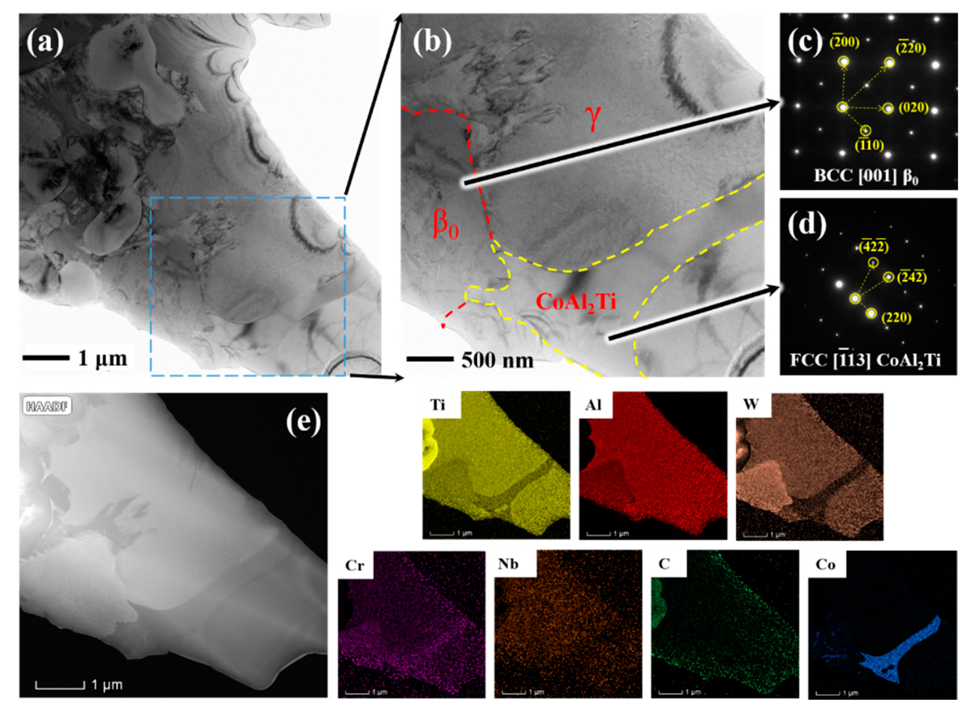
3.2. Microstructural Characterization

Figure 4 shows the microstructural evolution of the Ti–48Al–2Cr–2Nb composite coating with increasing WC content. Table 2 details the composition of the Ti–48Al–2Cr–2Nb composite coatings obtained from SEM spot scanning. The microstructure of the coating without WC is a dendrite crystal structure with a size of 6–15 μm, which is smaller than that of the cast TiAl alloy (Figure 4a,a1). When 5% and 10% WC were added, the star-shaped and spherical particles in the coating can be judged as TiC by point 3 in Table 2, mainly because the decomposition of WC provides a carbon source for the formation of TiC. Meanwhile, blocky and long ribbon structures appear in the coating. The point 2 scanning results showed a greater number of Ti atoms than Al atoms, indicating the β0 phase [20]. With the increase in WC addition, the blocky and long structure increases significantly, which is consistent with the experimental results of XRD. The β0 phase generation is due to the following reasons: the increased amount of W element as a strong β-element increases the possibility of generating the β0 phase, while the fast cooling and heating characteristics of laser cladding also increase the possibility of β0 phase generation. When 15% WC was added, some WC particles and network structures appeared in the coating as excess WC content had prevented their complete dissolution. The formation of the network structure is explained in detail in the TEM analysis.
Based on the analysis results of the point scan it can be seen that the point 1 is matrix phase, and the results show that the Ti/Al atomic ratio is not 1:1. Therefore, the matrix phase of the composite coating not only has TiAl but also a few Ti3Al phases. Meanwhile, we can see that in the matrix phase there is W, Nb, and Cr element solid solution. In the β0 phase we can also see that there are solid solutions of these elements, which is consistent with the experimental results of XRD. The solid solution of these elements can cause lattice distortion and play the role of solid solution strengthening.
Figure 5a shows the transmitted bright field phase with the addition of 10% WC, and the partial enlargement is shown in Figure 5b. Figure 5e displays a mapping of the local enlarged area of Figure 5a. According to the mapping results, it can be seen that the position shown in the yellow dotted area is the Co-rich phase, and this enrichment phase was identified as CoAl2Ti (FCC structure) by electron diffraction (Figure 5d). Pan et al. [21] found that liquid + α → CoAl2Ti + Ti (HT), where Ti (HT) is the high-temperature solid solution phase of Ti, readily occurs when Co is added. Xia et al. [22] found that CoAl2Ti tends to distribute at the grain boundary of γ–TiAl to form a network structure, similar to that observed in Figure 4d1. The mapping results reveal that the W in the coating is mainly concentrated in the red dotted area and the center of the spherical tissue. According to the crystal diffraction patterns, the area within the red dotted line is the β0 phase (Figure 5c). For the γ phase, W tends to replace Ti, while W replaces Al at the core of the body for the β0 phase, mainly due to the strong bond between Ti and W [23]. In the β0 phase, W replaces Al and then forms a Ti–W bond at eight angles. W more easily replaces Al in the β0 phase [24], resulting in the segregation of W in the β0 phase. W is also concentrated in the center of the spherical tissue, which was determined as TiC according to the mapping results. As can be seen from Figure 3 and Table 2, C is mainly used to form TiC and WC, and Cr is a β-stable element that is found to be distributed in the γ and β0 phases. Cr and Nb slightly partitioned to the β0 phase, which is because Cr and Nb are stabilizers for the β phase.
A literature review revealed [25,26] an approach aimed to trade off strength and ductility that build multi-phase microstructures and involves at least one ductile and one hard phase. In this coating, we can find that the CoAl2Ti (FCC) and γ phase can be used as a ductile phase, and the β0 and TiC phase can be used as a hard phase. We can judge that this multi-phase structure (CoAl2Ti, γ, β0, and TiC) can theoretically improve both the ductility and strength of the TiAl alloy.
Multi-phase structure alone is not enough; a stable interface is the key to improving material performance. Figure 6a shows there are no interfacial reactants in the interface of TiAl/β0 and TiAl/CoAl2Ti. An HRTEM image of the TiAl/CoAl2Ti interface is shown in Figure 6b. There is a good transition between the two phases. Figure 6c,d show the selected area electron diffraction (SAED) pattern from the interface of TiAl/β0 and TiAl/CoAl2Ti. Figure 6c shows [122]γ and [113]CoAl2Ti parallel, and the (022) plane of γ is parallel to the (220) plane of CoAl2Ti. Thus, their crystallographic orientation relationship can be expressed as:
[122]γ//[113]CoAl2Ti, (022)γ//(220)CoAl2Ti
There is an angle of 1.66° between the (420) plane and the (422) plane, and this can be approximated as a parallel crystal plane. This type of incoherent interface is made up of many parallel small interfaces called microfacets. Liu et al. found these small atomic-scale microfacets facilitated nucleation and growth and enhanced the mechanical properties of composite materials. This interface has a moderate interface energy and has a good effect on toughening. [27] In conclusion, these interfaces are beneficial for these composite coatings.
Figure 6d shows [011]γ and [112]β0 parallel, the (200) plane of γ is parallel to the (110) plane of β0, the (111) plane of γ is parallel to the (312) plane of β0, and the (311) plane of γ is parallel to the (402) plane of β0. Thus, their crystallographic orientation relationship can be expressed as:
[011]γ//[112]β0, (200) γ//(110)β0, (111)γ//(3120, (311)γ//(4020
The interface between the γ phase and β0 phase belongs to the coherent interface. The coherent interface has the lowest interfacial energy and the most stable interface, which is the most ideal interfacial relationship, and the interfacial relationship between them is of great help to the improvement of coating performance.

3.3. Microstructural Evolution

When the amount of WC was less than 10 at%, the WC particles completely decomposed during the laser cladding process. With the decomposition of WC, C appears in the molten pool. Previous work [28,29] revealed that the solidification path is shifted from the single β-phase to the peritectic reaction (L + β → α) with the addition of C. Therefore, the transformation sequence of the TiAl matrix was interpreted as follows: L → L + β → α + β → α + γ + β → α2 + γ + β0 [30]. To clarify the microstructural formation mechanism of the TiAl composite coatings, a schematic illustration of microstructure formed when the amount of WC was more than 10 at% is shown in Figure 7. A uniform distribution of the powder was observed before laser cladding (Figure 7a). Figure 7b shows that the molten pool formed during the laser cladding process, part of WC completely melted, and W, C, and Co entered the molten pool. WC that is not completely dissolved acts as a heteronucleation site, attracting C and Ti atoms to form TiC in the periphery. In the solidification processes, the high-temperature β and α phases of the TiAl alloy first appear (Figure 6c). The remaining liquid and α phases then form the CoAl2Ti phase. Because W, Cr, and Nb are all β-stable elements, TiAl alloys that solidify in the body-centered cubic β phase region are known as β-solidifying TiAl alloys [31]. As shown in Figure 7d, the phase in the composite coating is mainly the high-temperature β phase. As the temperature decreases, the β phase begins to transition into the γ phase and the α phase begins to transition into the α2 phase (Figure 7e) [32]. Due to the abundance of β-stable elements, some β elements remain at room temperature to form the β0 phase. Finally, the CoAl2Ti phase is distributed at the grain boundary of the γ phase, forming a network structure. Very little of the Ti3Al phase was found in the diagram, similar to that observed in the experiment. The relatively low amount of the Ti3Al phase is mainly due to γ phase following the Blackburn orientation relationship from α precipitate in the phase to form γ/α2 lamellar structure during alloy solidification. If the cooling rate is too fast, α phase transforms as a whole into the γ phase, i.e, γ massive transformation. So, in our experiment, no γ/α2 lamellar structure was observed.

3.4. Mechanical Property Analysis

Figure 8 shows the TiAl composite coating cross-sectional microhardness distribution of the depth direction, where the hardness distribution is divided into three regions, i.e., the cladding layer, transition zone, and substrate material. It can be seen that the hardness of the transition zone is between that of the cladding layer and the substrate material. The transition zone can cushion the coating and substrate and make the coating difficult to fall off. The hardness of the composite coating was found to increase with the WC content. When the WC content was 15 wt%, the average hardness of the coating reached 741.17 Hv0.2. The reasons for this increase in coating hardness were analyzed as follows: (1) The decomposition of WC forms a TiC ceramic phase, which is evenly distributed in the cladding layer. TiC has a high hardness, increasing the hardness of the coating. (2) Nb, Cr, and W are replacement atoms that produce lattice distortions and hinder dislocation movement, leading to an increase in hardness. (3) When the amount of WC is 10 or 15 wt%, there is a lot of the β0 phase present in the coating. β0 is the hard phase of the B2 structure, which also increases the hardness of the coating.
In this paper, nanoindentation test are carried out to reveal the strengthening mechanisms of coatings. Figure 9 shows the nanoindentation results of the TiAl composite coating, and Table 3 shows the specific values of the nanoindentation results. In this paper, we focus on the nanoindentation of these three phases (γ,β0 and TiC), which are more abundant and determine the properties of the coating. The load–depth curve of the nanoindentation in Figure 9a was analyzed to obtain Figure 9b–d. Figure 9b shows their nanohardness (H) and elastic modulus (E), similar to the results tested by others. The nanohardness relationship of these three phases is as follows: TiC > β0 > γ. The area enclosed by the loading curve and the X-axis is the total work done by the indenter (Wtot), the area enclosed by the loading curve and the unloading curve is the irreversible work (Wp), and the area enclosed by the unloading curve and the X-axis is the reversible work (Wu). The relationship between the three is Wtot = Wp + Wu, as shown in the upper left corner of Figure 9c. In general, we believe that the Wp/Wtot ratio is used to qualitatively characterize the ductility of the material, and the higher the Wp/Wtot ratio, the better the ductility. The appearance of β0 did not cause much harm to the ductility of the coating. The ratio of H/E and H3/E2 indicate the resistance against elastic strain and plastic deformation, respectively. η is the ratio of Wu and Wtot, which indicates the elasticity of the material surface. Consequently, a higher value of H/E, H3/E2, and η means better friction performance. The comparison of Figure 9d shows that the more phases β0 and TiC, the better the friction performance. According to the values of H3/E2 of β0 (0.089) and TiC (0.228), it can be seen that they have a strong resistance to plastic deformation and the wear mechanism is dominated by abrasive wear.
Further analysis of the mechanical and frictional properties of the coating by the results of nanoindentation was conducted. With reference to the value of Wp/Wtot, this shows that the β0 phase is helpful for the plasticity improvement of the coating. According to the above analysis, with the increase in WC addition, the β0 phase gradually increases while the α2 phase gradually decreases. The α2 phase is brittle due to its D019 structure (very little slip system). Therefore, it can be judged that the plasticity of the coating increases with the addition of WC. With reference to the value of H/E, H3/E2, and η, the β0 and TiC are favorable phases for frictional properties. With the increase in WC addition, the β0 and TiC gradually increase, so it can be judged that the friction performance of the coatings improves with the increase in WC addition.

3.5. Wear Performance and Analysis

In order to study the friction performance of TiAl composite coatings, dry sliding friction experiments were conducted. Figure 10a,b respectively display the friction coefficient curves and wear volumes of the matrix and composite coatings. The friction coefficient curve fluctuates greatly in the run-off stage and gradually becomes stable after 1200 s (Figure 10a). The friction coefficient of composite coatings showed little change. The 10 WC sample had the lowest friction coefficient. Figure 10b demonstrates that the wear volume of TiAl composite coating is significantly lower than that of TC4 substrate, and the composite coating shows a trend of increasing and then decreasing wear volume with the increase in WC. The 10 WC sample shows the most excellent friction properties. The 10 WC sample has the best frictional properties because the β0 phase, CoAl2Ti phase, and TiC appear in the 10 WC coating, and the multi-scale multi-phase structure of these phases achieves a strength–toughness match for the coating, resulting in a significant increase in wear resistance.
The wear mechanism of the TC4 and TiAl composite coatings was studied by SEM and the 3D morphology of the wear marks (Figure 11). Figure 11a shows furrows and slight delamination on the TC4 surface, indicating obvious abrasive wear and slight adhesive wear. Obvious abrasive wear is the main reason for the large wear volume of TC4. According to SEM and 3D morphology, it can be seen that the composite coatings all have obvious furrows, which is a typical mechanism of abrasive wear. Slight abrasive wear is the main reason for the small wear volume of coatings.
Further analysis of Figure 11 reveals an interesting phenomenon; with the increase in WC addition, the wear debris becomes smaller. Large spalling pits were found in the 0 WC sample, but no such phenomenon was found in the other samples. The possible reasons for the analysis of this phenomenon: TiAl alloys are brittle at room temperature, so TiAl composite coatings are susceptible to brittle spalling under the action of friction stress and produces large spalling pits. Large spalling pits correspond to large wear debris. The wear debris generally has high hardness and is not easily discharged in the friction process, so this is the reason for the large wear volume of the 0 WC sample. With the addition of WC, the spalling pits disappear and the wear debris become smaller. The main reasons for this are the γ, β0, CoAl2Ti, and TiC multiphase coordinated strengthening effect and that the hardness of the coatings increases while the plasticity increases. Under the action of friction, the brittleness of TiAl itself easily produces many micro-cracks, and the cracks continue to expand in the friction process, but when encountered with good plasticity of the material phase, (CoAl2Ti) they prevent the expansion of the crack, and the cracks are difficult to polymerize, causing the material to fracture and form brittle spalling pits. This is the reason for the addition of WC wear volume becomes smaller. However, when WC is added at 15%, the wear volume of the coating suddenly becomes larger again. It is obvious that there are cracks in Figure 11d. The formation of WC increases the brittleness of the coating and leads to cracking, which is the reason for the decline in the wear resistance of the 15 WC coating.
To further investigate the wear mechanism of the composite coating, an analysis of the wear debris was carried out. This wear debris can be detected through SEM in Figure 11. Figure 12b shows that the wear debris consist mainly of small particles of different sizes. The SEM-Mapping results show that the main composition of the wear debris is consistent with the TiAl matrix and no spalling of individual TiC particles was found. The main reason is that the in-situ-generated TiC is relatively small, uniformly distributed, and has a good interfacial relationship with the substrate. The TiC ceramic phase acts as a support site for load carrying in the friction process [33], slightly reducing the wear volume. This is one reason for the increased wear resistance with the addition of WC. In Figure 12a,c, the size of the wear debris is relatively small, while Figure 12d shows that there are some wear debris on the surface of grinding marks. The fine wear debris causes little damage to the coating and readily undergoes compaction to form a secondary protective layer in the grinding marks, greatly improving the wear resistance of the coating [34]. This is another reason for the increased wear resistance with the addition of WC. It is worth noting that spectrum 1 and 2 have a lot of oxygen present. Previous studies have found [35] that TiAl alloys tend to bond with oxygen during friction to form a brittle oxide layer, which tends to flake off and is one of the reasons for the poor wear resistance of TiAl alloys. With the addition of WC, the introduction of W increases, and W, Nb, and Cr are all antioxidant elements, which may also account for the increased wear resistance of the coatings.
From the above analysis, ceramic–metal multi-scale hybrid reinforcement plays a large role in improving the wear resistance of TiAl composite coatings. The formation of a strength–toughness matching microstructure in the TiAl alloys is the key to improving the wear resistance of TiAl coatings. To further improve the wear resistance of TiAl composite coatings, the addition of some oxidation-resistant elements is also a way to improve their wear resistance.

4. Conclusions

In this study, a wear-resistant TiAl composite coating was successfully fabricated on a TC4 surface by laser cladding, and the effect of adding different levels of WC on the phase, structure, and properties of TiAl composite coatings was studied, including detailed explanation of the wear mechanism of WC at different addition levels. The major results are thus presented:
(a)
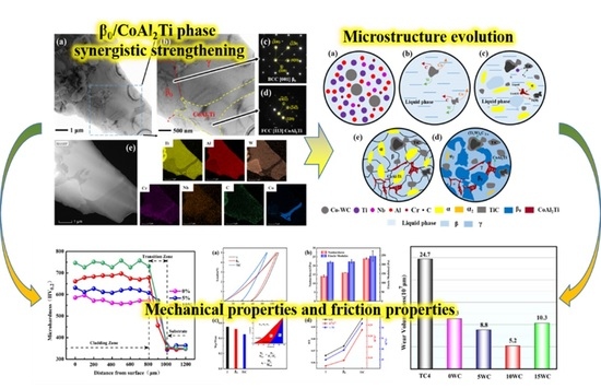
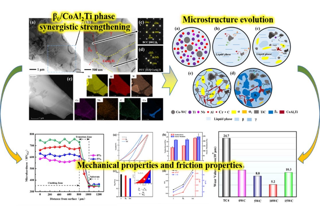
When WC was added, the β0, CoAl2Ti (FCC) and TiC phase appears in the composite coatings. These three phases, including the matrix phase, form a strength–toughness matching multi-phase structure. γ/β0 and γ/CoAl2Ti interface relationships guarantee the performance of the coating. The main solidification path of TiAl composite coatings prepared by laser cladding is β-solidifying, which generates finer microstructure and is more likely to produce the β0 phase.
(b)
The microhardness increased from 560 Hv0.2 to more than 740 Hv0.2 as the WC content increased from 0 to 15 at%. The results of the nanoindentation demonstrate that the β0 phase is a phase with the right strength and toughness to be beneficial for wear resistance.
(c)
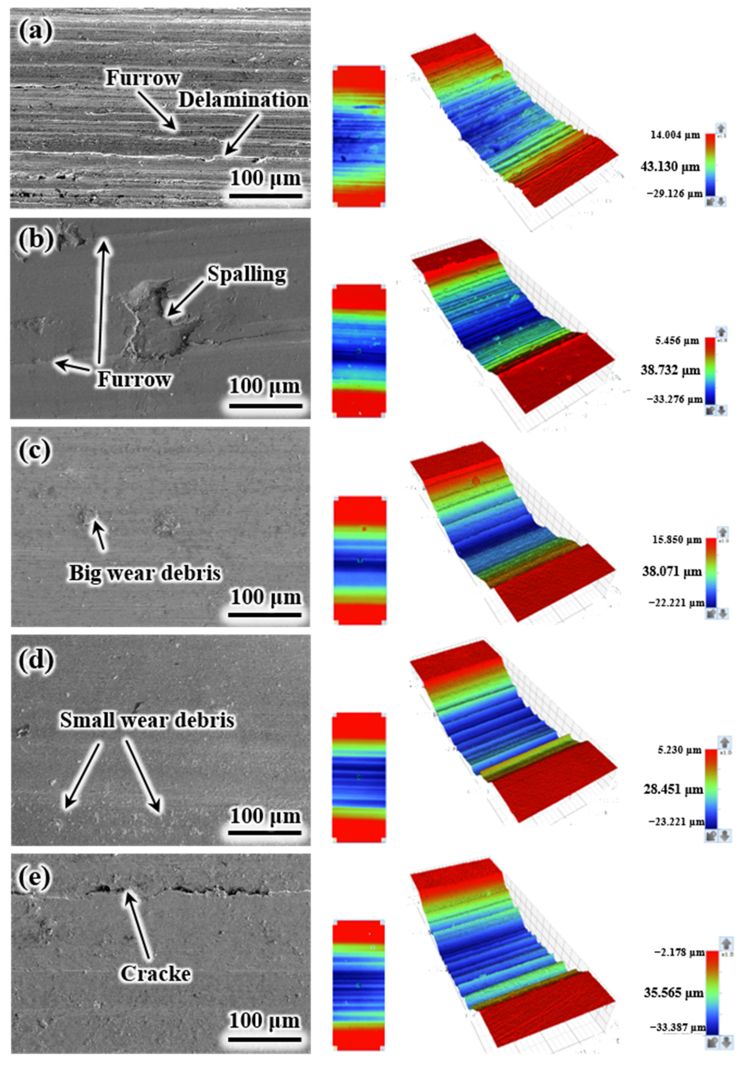
The main wear mechanism for TiAl composite coatings is abrasive wear. With the addition of WC, spalling pits disappears, wear debris becomes smaller during the friction process, and the wear volume is reduced. The coating exhibits the best frictional properties when WC is added at 10%. The key to improving the wear resistance of TiAl composite coatings is the formation of the strength–toughness matching structure, together with the addition of oxidation-resistant elements.

Author Contributions

Conceptualization, X.S. and H.C. (Hongzhi Cui); methodology, X.S., Y.Z. and G.M.; validation, G.M., H.C. (Hao Chen). and D.J.; formal analysis, X.S. and H.C. (Hongzhi Cui); investigation, Y.Z. and M.L.; data curation, Y.Z., Q.W. and X.Z.; writing—original draft preparation, Y.Z.; writing—review and editing, X.S.; visualization, G.M. and H.N.; supervision, X.S., D.J. and H.N.; project administration, X.S.; funding acquisition, X.S. and H.C. (Hongzhi Cui). All authors have read and agreed to the published version of the manuscript.

Funding

The authors are grateful for the financial support of the National Natural Science Foundation of China (U2106216, 51971121), the Taishan Scholarship of Climbing Plan (No. tspd 20161006) and Major-Special Science and Technology Projects in Shandong Province (2019JZZY010303, 2019JZZY010360).

Institutional Review Board Statement

Not applicable.

Informed Consent Statement

Not applicable.

Data Availability Statement

Not applicable.

Conflicts of Interest

The authors declare that they have no known competing financial interests or personal relationships that could appear to influence the work reported in this paper.

References

  1. Zhou, H.; Shi, X.; Lu, G.; Chen, Y.; Yang, Z.; Wu, C.; Ibrahim, A.M.M. Friction and wear behaviors of TC4 alloy with surface microporous channels filled by Sn-Ag-Cu and Al2O3 nanoparticles. Surf. Coat. Technol. 2020, 387, 125552. [Google Scholar] [CrossRef]
  2. Cheng, R.; Luo, X.; Huang, G.; Li, C.J. Corrosion and wear resistant WC17Co-TC4 composite coatings with fully dense microstructure enabled by in-situ forging of the large-sized WC17Co particles in cold spray. J. Mater. Process. Technol. 2021, 296, 117231. [Google Scholar] [CrossRef]
  3. Philip, J.T.; Mathew, J.; Kuriachen, B. Tribology of Ti6Al4V: A review. Friction 2019, 7, 497–536. [Google Scholar] [CrossRef] [Green Version]
  4. Ma, R.; Liu, Z.; Wang, W.; Xu, G.; Wang, W. Laser deposition melting of TC4/TiAl functionally graded material. Vacuum 2020, 177, 109349. [Google Scholar] [CrossRef]
  5. Gao, Z.; Wang, L.; Wang, Y.; Lyu, F.; Zhan, X. Crack defects and formation mechanism of FeCoCrNi high entropy alloy coating on TC4 titanium alloy prepared by laser cladding. J. Alloy. Compd. 2022, 903, 163905. [Google Scholar] [CrossRef]
  6. Chen, G.; Peng, Y.; Zheng, G.; Qi, Z.; Wang, M.; Yu, H.; Liu, C.T. Polysynthetic twinned TiAl single crystals for high-temperature applications. Nat. Mater. 2016, 15, 876–881. [Google Scholar] [CrossRef]
  7. Yue, H.; Peng, H.; Li, R.; Yang, J.; Gao, R.; Zhang, S.; Chen, Y. Metastable phase and microstructural degradation of a TiAl alloy produced via selective electron beam melting. Vacuum 2021, 192, 110491. [Google Scholar] [CrossRef]
  8. Lou, M.; Chen, X.; Xu, K.; Deng, Z.; Chen, L.; Lv, J.; Wang, L. Temperature-induced wear transition in ceramic-metal composites. Acta. Mater. 2021, 205, 116545. [Google Scholar] [CrossRef]
  9. He, X.; Song, R.G.; Kong, D.J. Effects of TiC on the microstructure and properties of TiC/TiAl composite coating prepared by laser cladding. Opt. Laser. Technol. 2019, 112, 339–348. [Google Scholar] [CrossRef]
  10. Lee, B.; Lee, D.; Lee, J.H.; Ryu, H.J.; Hong, S.H. Enhancement of toughness and wear resistance in boron nitride nanoplatelet (BNNP) reinforced Si3N4 nanocomposites. Sci. Rep. 2016, 6, 27609. [Google Scholar] [CrossRef]
  11. Bai, H.; Zhong, L.; Kang, L.; Liu, J.; Zhuang, W.; Lv, Z.; Xu, Y. A review on wear-resistant coating with high hardness and high toughness on the surface of titanium alloy. J. Alloy. Compd. 2021, 882, 160645. [Google Scholar] [CrossRef]
  12. Song, X.; Cui, H.; Han, Y.; Ding, L.; Song, Q. Ti2Al(C, N) Solid Solution Reinforcing TiAl-Based Composites: Evolution of a Core-Shell Structure, Interfaces, and Mechanical Properties. ACS Appl. Mater. Inter. 2018, 10, 16783–16792. [Google Scholar] [CrossRef] [PubMed]
  13. Cui, S.; Cui, C.; Xie, J.; Liu, S.; Shi, J. Carbon fibers coated with graphene reinforced TiAl alloy composite with high strength and toughness. Sci. Rep. 2018, 8, 2364. [Google Scholar] [CrossRef] [PubMed] [Green Version]
  14. Cobbinah, P.V.; Matizamhuka, W.; Machaka, R.; Shongwe, M.B.; Yamabe-Mitarai, Y. The effect of Ta additions on the oxidation resistance of SPS-produced TiAl alloys. Int. J. Adv. Manuf. Technol. 2020, 106, 3203–3215. [Google Scholar] [CrossRef]
  15. Tian, S.; He, A.; Liu, J.; Zhang, Y.; Yang, Y.; Zhang, Y.; Jiang, H. Oxidation resistance of TiAl alloy improved by hot-pack rolling and cyclic heat treatment. Mater. Charact. 2021, 178, 111196. [Google Scholar]
  16. Maliutina, I.N.; Si-Mohand, H.; Sijobert, J.; Bertrand, P.; Lazurenko, D.V.; Bataev, I.A. Structure and oxidation behavior of γ-TiAl coating produced by laser cladding on titanium alloy. Surf. Coat. Technol. 2017, 319, 136–144. [Google Scholar] [CrossRef]
  17. Ma, G.; Cui, H.; Jiang, D.; Chen, H.; Hu, X.; Zhang, G.; Song, X. The evolution of multi and hierarchical carbides and their collaborative wear-resisting effects in CoCrNi/WC composite coatings via laser cladding. Mater. Today Commun. 2022, 30, 103223. [Google Scholar] [CrossRef]
  18. Jiang, D.; Cui, H.; Chen, H.; Zhao, X.; Ma, G.; Song, X. Wear and corrosion properties of B4C-added CoCrNiMo high-entropy alloy coatings with in-situ coherent ceramic. Mater. Des. 2021, 210, 110068. [Google Scholar] [CrossRef]
  19. Xu, X.; Ding, H.; Huang, H.; Liang, H.; Chen, R.; Guo, J.; Fu, H. Microstructure and elevated temperature tensile property of Ti–46Al–7Nb-(W,Cr,B) alloy compared with binary and ternary TiAl alloy. Mater. Sci. Eng. A 2021, 807, 140902. [Google Scholar] [CrossRef]
  20. Li, X.; Tang, H.; Xing, W.; Zhao, P.; Chen, B.; Ma, Y.; Liu, K. Microstructural stability, phase evolution and mechanical properties of a forged W-modified high-Mn β-γ-TiAl alloy. Intermetallics 2021, 136, 107230. [Google Scholar] [CrossRef]
  21. Pan, Y.; Lu, X.; Hui, T.; Liu, C.; Liu, B.; Xu, W.; Zhang, J. High-temperature oxidation behaviour of TiAl alloys with Co addition. J. Mater. Sci. 2020, 56, 815–827. [Google Scholar] [CrossRef]
  22. Xia, Y.; Yu, P.; Schaffer, G.B.; Qian, M. Cobalt-doped Ti–48Al–2Cr–2Nb alloy fabricated by cold compaction and pressureless sintering. Mater. Sci. Eng. A 2013, 574, 176–185. [Google Scholar] [CrossRef]
  23. Yu, R.; H, L.L.; Ye, H.Q. Effect of W on structural stability of TiAl intermetallics and the site preference of W. Phys. Rev. B 2002, 65, 184102. [Google Scholar] [CrossRef]
  24. Hu, H.; Wu, X.; Wang, R.; Li, W.; Liu, Q. Phase stability, mechanical properties and electronic structure of TiAl alloying with W, Mo, Sc and Yb: First-principles study. J. Alloy. Compd. 2016, 658, 689–696. [Google Scholar] [CrossRef]
  25. Choudhuri, D.; CampBell, A. Interface dominated deformation mechanisms in two-phase fcc/B2 nanostructures: Nishiyama-Wasserman vs. Kurdjumov-Sachs interfaces. Comp. Mater. Sci. 2020, 177, 109577. [Google Scholar] [CrossRef]
  26. Gwalani, B.; Gangireddy, S.; Zheng, Y.; Soni, V.; Mishra, R.S.; Banerjee, R. Influence of ordered L12 precipitation on strain-rate dependent mechanical behavior in a eutectic high entropy alloy. Sci. Rep. 2019, 9, 6371. [Google Scholar] [CrossRef] [Green Version]
  27. Liu, P.; Sun, D.; Han, X.; Wang, Q. Investigation on the crystallographic orientation relationships and interface atomic structures in an in-situ Ti2AlN/TiAl composite. Mater. Des. 2017, 130, 239–249. [Google Scholar] [CrossRef]
  28. Schwaighofer, E.; Rashkova, B.; Clemens, H.; Stark, A.; Mayer, S. Effect of carbon addition on solidification behavior, phase evolution and creep properties of an intermetallic β-stabilized γ-TiAl based alloy. Intermetallics 2014, 46, 173–184. [Google Scholar] [CrossRef] [Green Version]
  29. Wu, Z.; Hu, R.; Zhang, T.; Zhang, F.; Kou, H.; Li, J. Understanding the role of carbon atoms on microstructure and phase transformation of high Nb containing TiAl alloys. Mater. Charact. 2017, 124, 1–7. [Google Scholar] [CrossRef]
  30. Gao, B.; Peng, H.; Liang, Y.; Lin, J.; Chen, B. Electron beam melted TiC/high Nb–TiAl nanocomposite: Microstructure and mechanical property. Mater. Sci. Eng. A 2021, 811, 141059. [Google Scholar] [CrossRef]
  31. Cho, K.; Kawabata, H.; Hayashi, T.; Yasuda, H.Y.; Nakashima, H.; Takeyama, M.; Nakano, T. Peculiar microstructural evolution and tensile properties of β-containing γ-TiAl alloys fabricated by electron beam melting. Addit. Manuf. 2021, 46, 102091. [Google Scholar] [CrossRef]
  32. Wen, D.; Huang, S.; Guo, B.; Shan, D.; Zong, Y. Effect of hydrogen on γ−phase transformation and texture evolution of a TiAl−based alloy deformed at elevated temperature. Mater. Sci. Eng. A 2017, 699, 176–184. [Google Scholar] [CrossRef]
  33. Cheng, J.; Yu, Y.; Fu, L.; Qiao, Z.; Li, J.; Yang, J.; Liu, W. Effect of TiB2 on dry-sliding tribological properties of TiAl intermetallics. Tribol. Int. 2013, 62, 91–99. [Google Scholar] [CrossRef]
  34. Yang, Y.; Wang, C.; Gesang, Y.; Shang, H. Fretting wear evolution of γ-TiAl alloy. Tribol. Int. 2021, 154, 106721. [Google Scholar] [CrossRef]
  35. Qiu, J.; Fu, Z.; Liu, B.; Liu, Y.; Yan, J.; Pan, D.; Zhang, W.; Baker, I. Effects of niobium particles on the wear behavior of powder metallurgical γ-TiAl alloy in different environments. Wear 2019, 434–435, 202964. [Google Scholar] [CrossRef]
Figure 1. (a) Morphology of the WC powder imaged by SEM and (b) partial enlargement of (a).
Coatings 12 01593 g001
Figure 2. Cross-sectional SEM images of bonding area between the Ti–48Al–2Cr–2Nb composite coatings and substrate: (a) 0 WC; (b) 5 WC; (c) 10 WC; (d) 15 WC.
Coatings 12 01593 g002
Figure 3. (a) XRD patterns of coatings with different WC contents. (b) Local enlargement of the XRD patterns of added coatings with different WC content.
Coatings 12 01593 g003
Figure 4. Cross-sectional SEM images of the Ti–48Al–2Cr–2Nb composite coatings: (a) 0 WC; (b) 5 WC; (c) 10 WC; (d) 15 WC. (a1d1) Enlarged microstructures of the red boxed area in (ad).
Coatings 12 01593 g004
Figure 5. TEM characterization of the 10 WC composite coating. (a) Bright-field TEM image. (b) The Bright-field TEM of partial enlargement (a,c,d) SAED pattern of the β0 phase and CoAl2Ti phase. (e) TEM-HAADF image of the TEM-EDS mappings of (a).
Coatings 12 01593 g005
Figure 6. (a) Typical bright field image of TiAl, β0, CoAl2Ti triple phase coexistence. (b) An HRTEM of TiAl and CoAl2Ti phase interface. (c,d) The SADE of γ and CoAl2Ti interface and γ and β0 interface, respectively.
Coatings 12 01593 g006
Figure 7. Schematic diagram of the 10 WC and 15 WC composite coatings during the solidification process. (a) The condition of powder before laser cladding; (b) The condition of molten pool; (c) The state in which the phases begin to precipitate during solidification; (d) A state in which the liquid phase has all disappeared; (e) Final phase distribution at room temperature.
Coatings 12 01593 g007
Figure 8. Microhardness distribution along the depth direction of a cross-section of the TiAl composite coating.
Coatings 12 01593 g008
Figure 9. (a) Load–depth curves for nanoindentation of γ β0 and TiC phases. (b) Nanohardness and elastic modulus results for γ β0 and TiC phases. (c) The Wp/Wtot results for γ β0 and TiC phases, where the areas are represented by Wp, Wu, and Wtot. (d) H/E, H3/E2, and η comparison of results.
Coatings 12 01593 g009
Figure 10. (a) Friction coefficient curves of the matrix and composite coatings. (b) Wear volumes of the matrix and composite coatings.
Coatings 12 01593 g010
Figure 11. Wear morphologies of the composite coatings and corresponding 3D morphologies of the wear scar of the composite coatings: (a) TC4; (b) 0 WC; (c) 5 WC; (d) 10 WC; (e) 15 WC.
Coatings 12 01593 g011
Figure 12. Wear debris morphologies of the TiAl + 10 WC composite coatings (a,c). (b) Partial enlargement of the pink area of (a) and results of SEM-Mapping. Spectrum 1 and 2 show the results of SEM-EDS, and (d) shows frictional surface morphology of the TiAl + 10 WC composite coatings.
Coatings 12 01593 g012
Table 1. Nominal elemental contents for the 0 WC to 15 WC powders.
m(Ti)/gm(Al)/gm(Nb)/gm(Cr)/gm(WC)/g
0 WC17.8210.011.400.860
5 WC15.768.871.270.713.39
10 WC14.017.881.130.636.35
15 WC12.457.011.010.568.97
Table 2. Composition of the Ti–48Al–2Cr–2Nb composite coatings obtained from SEM-EDS analysis.
TiAlWCNbCr
Point 151.4341.113.08-2.032.35
Point 247.9840.936.07-2.602.41
Point 365.46--31.54--
Table 3. Specific results of nanoindentation of TiAl composite coatings.
PhaseHv(H) (GPa)E (GPa)Wp/WtotH/EH3/E2η (%)
γ14.16 ± 0.64212.92 ± 5.330.550.0660.06344.97
β016.08 ± 0.04216.72 ± 9.780.520.0740.08947.71
TiC24.02 ± 0.42246.38 ± 27.660.450.0970.22855.20
Publisher’s Note: MDPI stays neutral with regard to jurisdictional claims in published maps and institutional affiliations.

