
Numerical Study on Particle Behavior and Deposition Accuracy in Cold Spray Additive Manufacturing
Abstract
:1. Introduction
2. Methodology
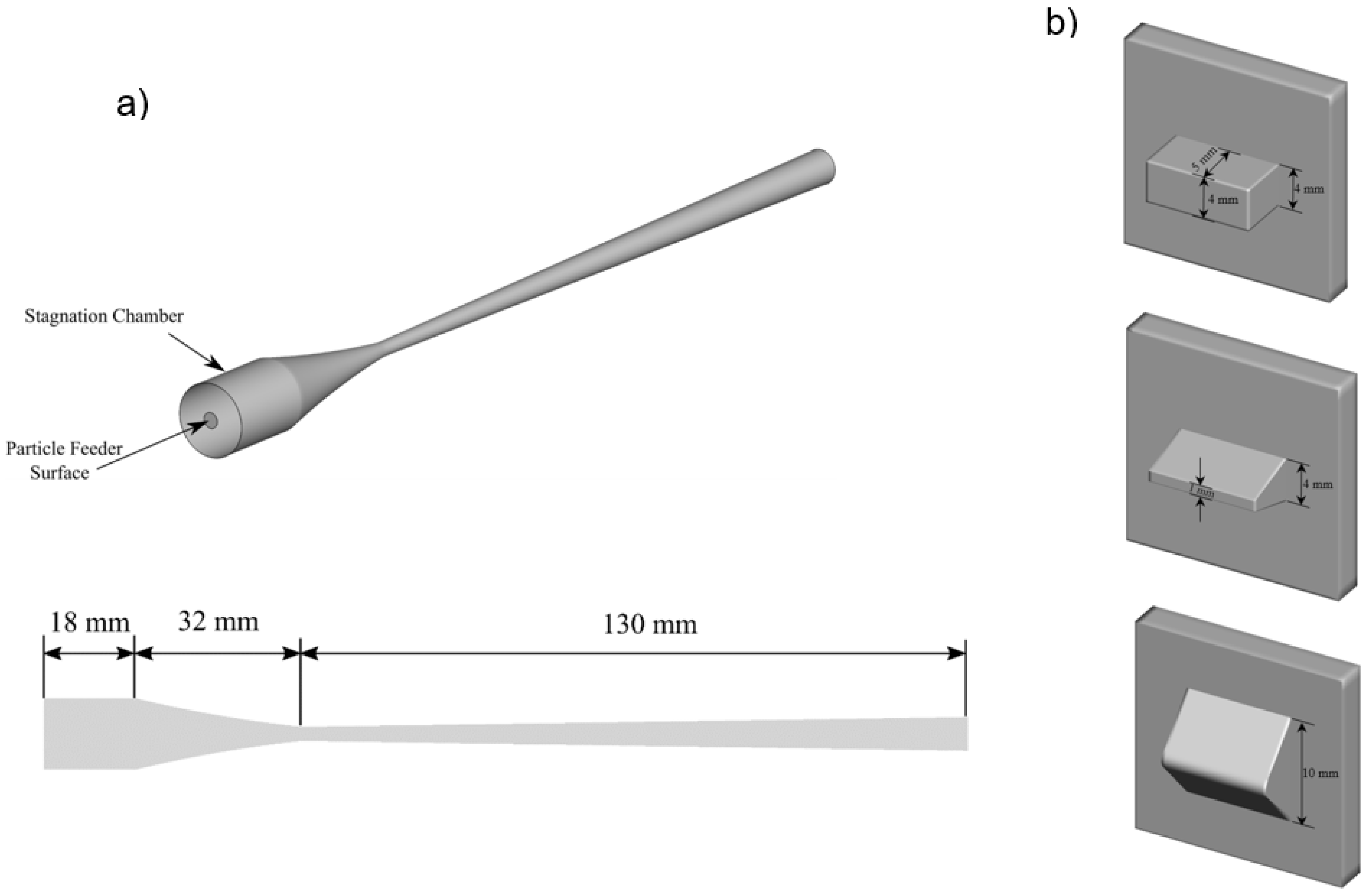
2.1. Geometry
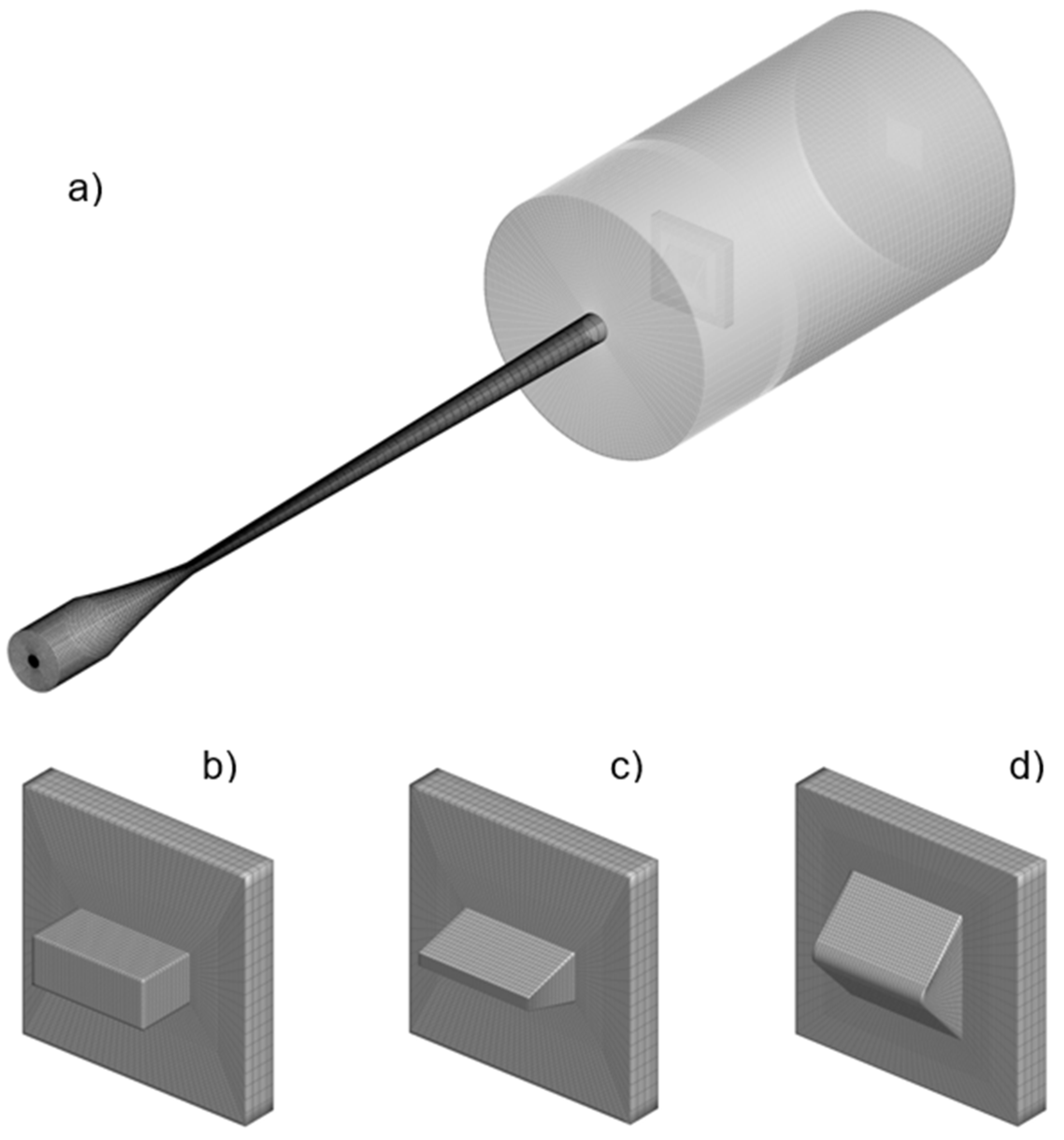
2.2. Computational Domain
2.3. Boundary Conditions
2.4. Numerical Solver
3. Results
3.1. Gas Phase
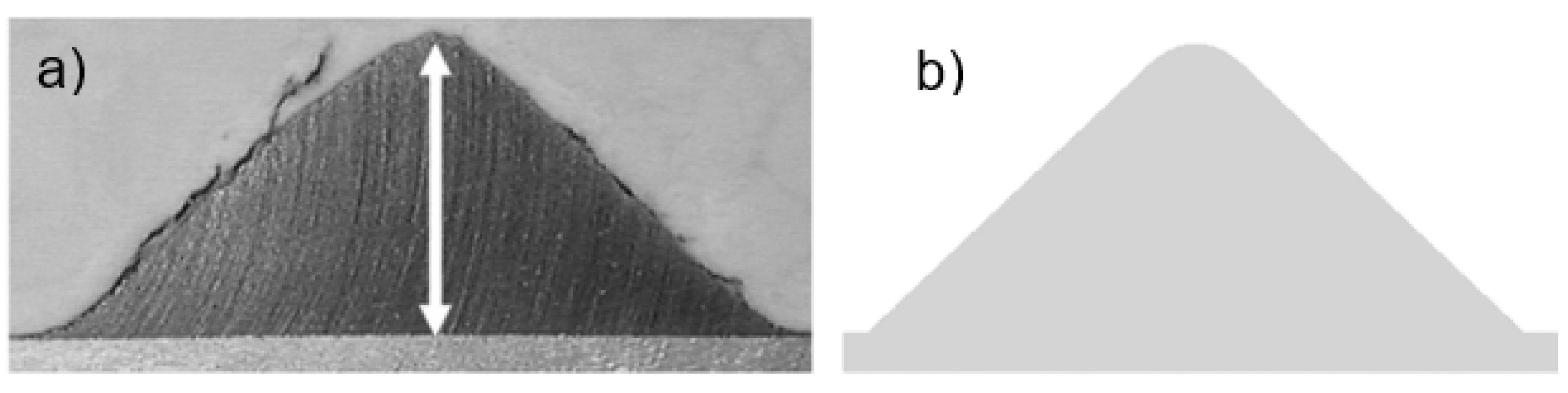
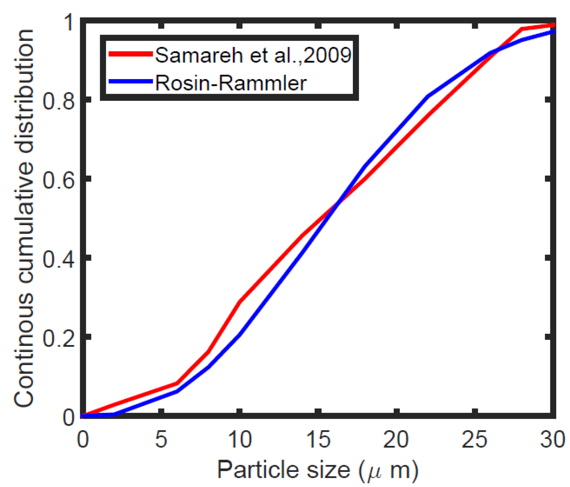
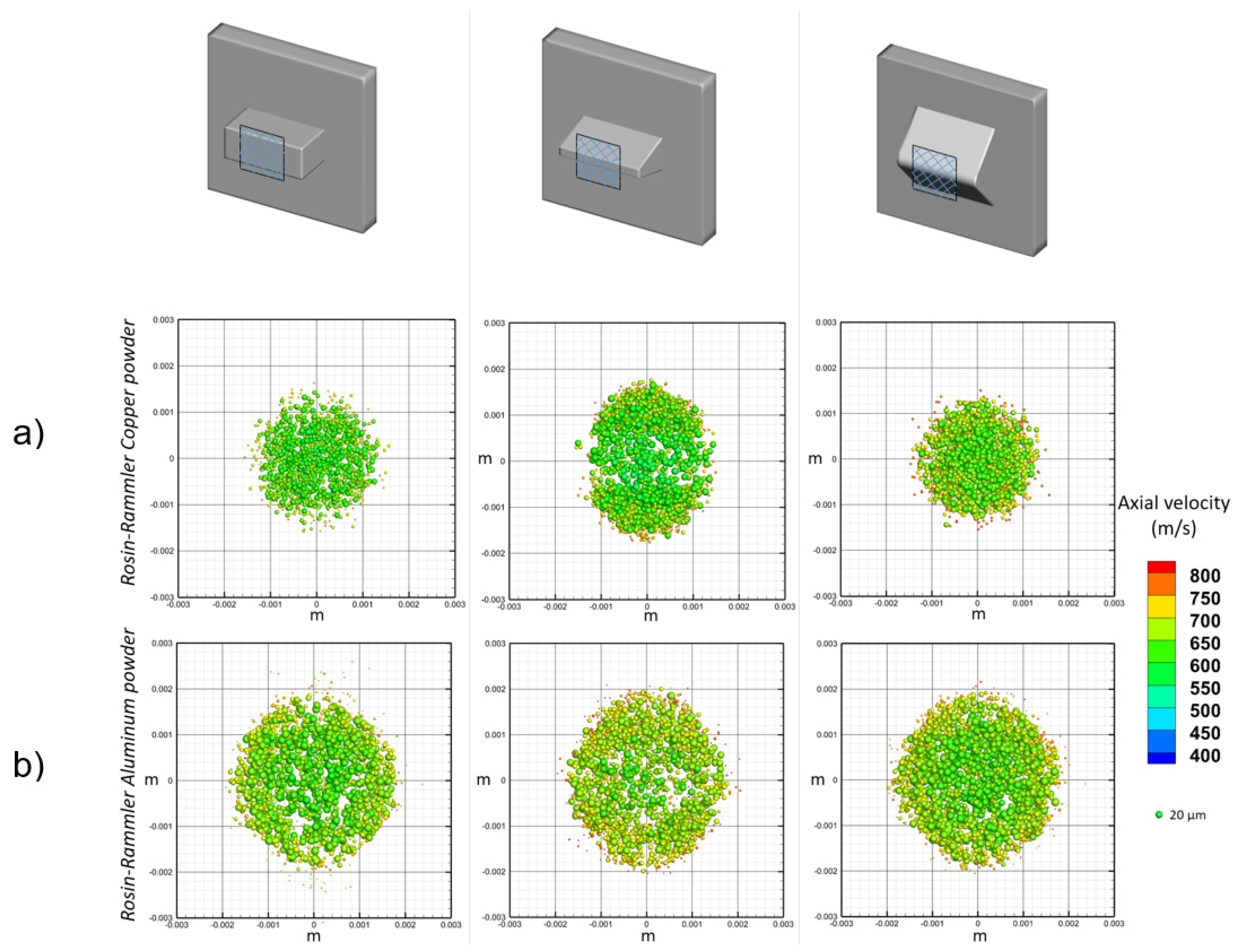
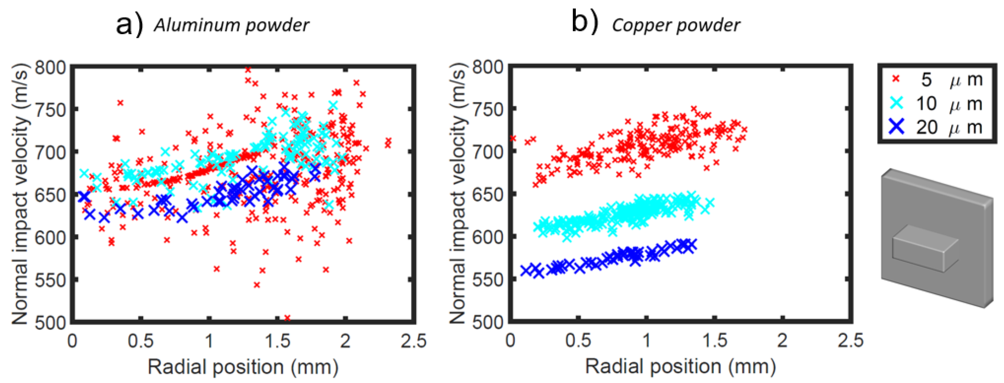
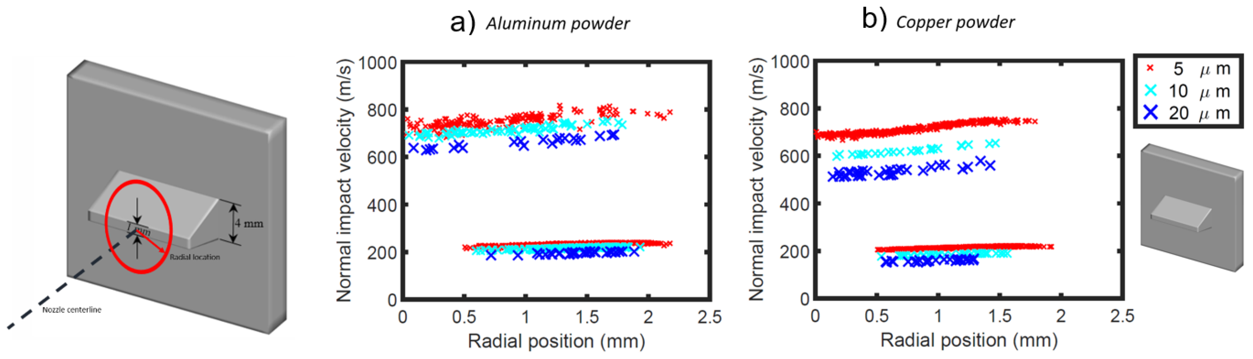
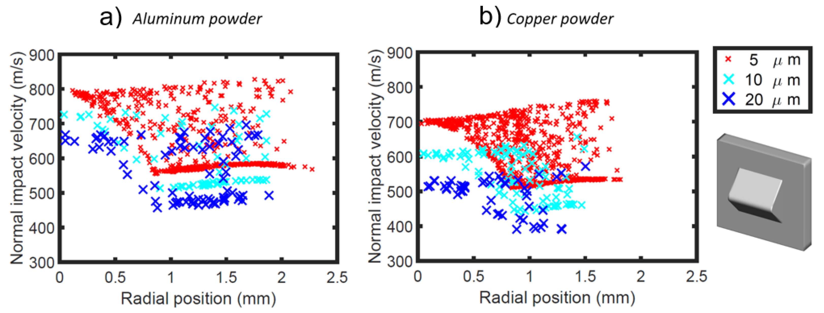
3.2. Discrete Phase
4. Conclusions
Author Contributions
Funding
Institutional Review Board Statement
Informed Consent Statement
Data Availability Statement
Acknowledgments
Conflicts of Interest
References
- Guo, D.; Kazasidis, M.; Hawkins, A.; Fan, N.; Leclerc, Z.; MacDonald, D.; Nastic, A.; Nikbakht, R.; Ortiz-Fernandez, R.; Rahmati, S.; et al. Cold Spray: Over 30 Years of Development toward a Hot Future. J. Therm. Spray Technol. 2022, 31, 866–907. [Google Scholar] [CrossRef]
- Chen, C.; Xie, Y.; Yan, X.; Yin, S.; Fukanuma, H.; Huang, R.; Zhao, R.; Wang, J.; Ren, Z.; Liu, M.; et al. Effect of hot isostatic pressing (HIP) on microstructure and mechanical properties of Ti6Al4V alloy fabricated by cold spray additive manufacturing. Addit. Manuf. 2019, 27, 595–605. [Google Scholar] [CrossRef]
- Yin, S.; Cavaliere, P.; Aldwell, B.; Jenkins, R.; Liao, H.; Li, W.; Lupoi, R. Cold spray additive manufacturing and repair: Fundamentals and applications. Addit. Manuf. 2018, 21, 628–650. [Google Scholar] [CrossRef]
- Schmidt, T.; Assadi, H.; Gärtner, F.; Richter, H.; Stoltenhoff, T.; Kreye, H.; Klassen, T. From particle acceleration to impact and bonding in cold spraying. J. Therm. Spray Technol. 2009, 18, 794. [Google Scholar] [CrossRef] [Green Version]
- Luo, X.-T.; Yao, M.-L.; Ma, N.; Takahashi, M.; Li, C.-J. Deposition behavior, microstructure and mechanical properties of an in-situ micro-forging assisted cold spray enabled additively manufactured Inconel 718 alloy. Mater. Des. 2018, 155, 384–395. [Google Scholar] [CrossRef]
- Kosarev, V.F.; Klinkov, S.V.; Melamed, B.M.; Nepochatov, Y.K.; Ryashin, N.S.; Shikalov, V.S. Cold spraying for power electronics: Deposition of thick topologically patterned copper layers on ceramics. AIP Conf. Proc. 2018, 2027, 030047. [Google Scholar]
- Shikalov, V.S.; Klinkov, S.V.; Kosarev, V.F. Cold spray deposition of aluminum coating onto an erodible material. Thermophys. Aeromech. 2019, 26, 729–737. [Google Scholar] [CrossRef]
- Sova, A.; Smurov, I.; Doubenskaia, M.; Petrovskiy, P. Deposition of aluminum powder by cold spray micronozzle. Int. J. Adv. Manuf. Technol. 2018, 95, 3745–3752. [Google Scholar] [CrossRef]
- Sova, A.; Grigoriev, S.; Okunkova, A.; Smurov, I. Potential of cold gas dynamic spray as additive manufacturing technology. Int. J. Adv. Manuf. Technol. 2013, 69, 2269–2278. [Google Scholar] [CrossRef]
- Assadi, H.; Kreye, H.; Gärtner, F.; Klassen, T. Cold spraying—A materials perspective. Acta Mater. 2016, 116, 382–407. [Google Scholar] [CrossRef] [Green Version]
- Bagherifard, S.; Monti, S.; Zuccoli, M.V.; Riccio, M.; Kondás, J.; Guagliano, M. Cold spray deposition for additive manufacturing of freeform structural components compared to selective laser melting. Mater. Sci. Eng. A 2018, 721, 339–350. [Google Scholar] [CrossRef]
- Oyinbo, S.T.; Jen, T.-C. Investigation of the process parameters and restitution coefficient of ductile materials during cold gas dynamic spray (CGDS) using finite element analysis. Addit. Manuf. 2020, 31, 100986. [Google Scholar] [CrossRef]
- Garmeh, S.; Jadidi, M.; Dolatabadi, A. Three-dimensional modeling of cold spray for additive manufacturing. J. Therm. Spray Technol. 2020, 29, 38–50. [Google Scholar] [CrossRef]
- Samareh, B.; Dolatabadi, A. Dense particulate flow in a cold gas dynamic spray system. J. Fluids Eng. 2008, 130, 81702. [Google Scholar] [CrossRef]
- Jenkins, R.; Aldwell, B.; Yin, S.; Chandra, S.; Morgan, G.; Lupoi, R. Solid state additive manufacture of highly-reflective Al coatings using cold spray. Opt. Laser Technol. 2019, 115, 251–256. [Google Scholar] [CrossRef]
- Cavaliere, P.; Silvello, A. Processing parameters affecting cold spay coatings performances. Int. J. Adv. Manuf. Technol. 2014, 71, 263–277. [Google Scholar] [CrossRef]
- Sova, A.; Okunkova, A.; Grigoriev, S.; Smurov, I. Velocity of the particles accelerated by a cold spray micronozzle: Experimental measurements and numerical simulation. J. Therm. Spray Technol. 2013, 22, 75–80. [Google Scholar] [CrossRef]
- Wu, H.; Xie, X.; Liu, M.; Verdy, C.; Zhang, Y.; Liao, H.; Deng, S. Stable layer-building strategy to enhance cold-spray-based additive manufacturing. Addit. Manuf. 2020, 35, 101356. [Google Scholar] [CrossRef]
- Wu, H.; Liu, S.; Zhang, Y.; Liao, H.; Raoelison, R.-N.; Deng, S. New process implementation to enhance cold spray-based additive manufacturing. J. Therm. Spray Technol. 2021, 30, 1284–1293. [Google Scholar] [CrossRef]
- Ikeuchi, D.; Vargas-Uscategui, A.; Wu, X.; King, P.C. Data-efficient neural network for track profile modelling in cold spray additive manufacturing. Appl. Sci. 2021, 11, 1654. [Google Scholar] [CrossRef]
- Vanerio, D.; Kondas, J.; Guagliano, M.; Bagherifard, S. 3D modelling of the deposit profile in cold spray additive manufacturing. J. Manuf. Process. 2021, 67, 521–534. [Google Scholar] [CrossRef]
- Özdemir, O.Ç.; Conahan, J.M.; Müftü, S. Particle Velocimetry, CFD, and the Role of Particle Sphericity in Cold Spray. Coatings 2020, 10, 1254. [Google Scholar] [CrossRef]
- Ozdemir, O.C.; Chen, Q.; Muftu, S.; Champagne, V.K. Modeling the continuous heat generation in the cold spray coating process. J. Therm. Spray Technol. 2019, 28, 108–123. [Google Scholar] [CrossRef]
- Sudhan, K.H.; Prasad, G.K.; Kothurkar, N.K.; Srikrishnan, A.R. Studies on supersonic cold spray deposition of microparticles using a bell-type nozzle. Surf. Coat. Technol. 2020, 383, 125244. [Google Scholar] [CrossRef]
- Kotoban, D.; Grigoriev, S.; Okunkova, A.; Sova, A. Influence of a shape of single track on deposition efficiency of 316L stainless steel powder in cold spray. Surf. Coat. Technol. 2017, 309, 951–958. [Google Scholar] [CrossRef]
- Samareh, B.; Stier, O.; Lüthen, V.; Dolatabadi, A. Assessment of CFD modeling via flow visualization in cold spray process. J. Therm. Spray Technol. 2009, 18, 934. [Google Scholar] [CrossRef]
- Samareh, B.; Dolatabadi, A. A three-dimensional analysis of the cold spray process: The effects of substrate location and shape. J. Therm. Spray Technol. 2007, 16, 634–642. [Google Scholar] [CrossRef]
- Fluent, A. Ansys Fluent Theory Guide; ANSYS Inc.: Canonsburg, PA, USA, 2013. [Google Scholar]
- Jadidi, M.; Moghtadernejad, S.; Dolatabadi, A. Numerical modeling of suspension HVOF spray. J. Therm. Spray Technol. 2016, 25, 451–464. [Google Scholar] [CrossRef]
- Jadidi, M.; Yeganeh, A.Z.; Dolatabadi, A. Numerical study of suspension HVOF spray and particle behavior near flat and cylindrical substrates. J. Therm. Spray Technol. 2018, 27, 59–72. [Google Scholar] [CrossRef]
- Jadidi, M.; Moghtadernejad, S.; Dolatabadi, A. A comprehensive review on fluid dynamics and transport of suspension/liquid droplets and particles in High-Velocity Oxygen-Fuel (HVOF) thermal spray. Coatings 2015, 5, 576–645. [Google Scholar] [CrossRef] [Green Version]
- Faeth, G.M. Spray Atomization and Combustion. In Proceedings of the 24th Aerospace Sciences Meeting, Reno, NV, USA, 6–9 January 1986. [Google Scholar] [CrossRef]
- Amsden, A.A.; O’Rourke, P.J.; Butler, T.D. KIVA-II: A Computer Program for Chemically Reactive Flows with Sprays; Technical Report LA-11560-MS, UC-96; Los Alamos National Lab: Los Alamos, NM, USA, 1989. [Google Scholar]
- Crowe, C.T. Drag coefficient of particles in a rocket nozzle. AIAA J. 1967, 5, 1021–1022. [Google Scholar] [CrossRef]
- Champagne, V.K.; Helfritch, D.J.; Dinavahi, S.P.G.; Leyman, P.F. Theoretical and experimental particle velocity in cold spray. J. Therm. Spray Technol. 2011, 20, 425–431. [Google Scholar] [CrossRef]
- Jen, T.-C.; Li, L.; Cui, W.; Chen, Q.; Zhang, X. Numerical investigations on cold gas dynamic spray process with nano- and microsize particles. Int. J. Heat Mass Transf. 2005, 48, 4384–4396. [Google Scholar] [CrossRef]
- Lupoi, R.; O’Neill, W. Powder stream characteristics in cold spray nozzles. Surf. Coat. Technol. 2011, 206, 1069–1076. [Google Scholar] [CrossRef] [Green Version]
- Zabihi Yeganeh, A.; Jadidi, M.; Moreau, C.; Dolatabadi, A. Numerical modeling of aerosol deposition process. Surf. Coat. Technol. 2019, 370, 269–287. [Google Scholar] [CrossRef]
- Schmidt, K.; Buhl, S.; Davoudi, N.; Godard, C.; Merz, R.; Raid, I.; Kerscher, E.; Kopnarski, M.; Müller-Renno, C.; Ripperger, S.; et al. Ti surface modification by cold spraying with TiO2 microparticles. Surf. Coat. Technol. 2017, 309, 749–758. [Google Scholar] [CrossRef]
- Gilmore, D.L.; Dykhuizen, R.C.; Neiser, R.A.; Smith, M.F.; Roemer, T.J. Particle velocity and deposition efficiency in the cold spray process. J. Therm. Spray Technol. 1999, 8, 576–582. [Google Scholar] [CrossRef]
- Zhu, W.; Zhang, X.; Zhang, M.; Tian, X.; Li, D. Integral numerical modeling of the deposition profile of a cold spraying process as an additive manufacturing. Prog. Addit. Manuf. 2019, 4, 357–370. [Google Scholar] [CrossRef]
- Ikeuchi, D.; Vargas-Uscategui, A.; Wu, X.; King, P.C. Neural network modelling of track profile in cold spray additive manufacturing. Materials 2019, 12, 2827. [Google Scholar] [CrossRef] [Green Version]
- Cao, C.; Li, W.; Zhang, Z.; Yang, X.; Xu, Y. Cold Spray Additive Manufacturing of Ti6Al4V: Special Nozzle Design Using Numerical Simulation and Experimental Validation. Coatings 2022, 12, 210. [Google Scholar] [CrossRef]


Publisher’s Note: MDPI stays neutral with regard to jurisdictional claims in published maps and institutional affiliations. |
© 2022 by the authors. Licensee MDPI, Basel, Switzerland. This article is an open access article distributed under the terms and conditions of the Creative Commons Attribution (CC BY) license (https://creativecommons.org/licenses/by/4.0/).
Share and Cite
Garmeh, S.; Jadidi, M. Numerical Study on Particle Behavior and Deposition Accuracy in Cold Spray Additive Manufacturing. Coatings 2022, 12, 1546. https://doi.org/10.3390/coatings12101546
Garmeh S, Jadidi M. Numerical Study on Particle Behavior and Deposition Accuracy in Cold Spray Additive Manufacturing. Coatings. 2022; 12(10):1546. https://doi.org/10.3390/coatings12101546
Chicago/Turabian StyleGarmeh, Saeed, and Mehdi Jadidi. 2022. "Numerical Study on Particle Behavior and Deposition Accuracy in Cold Spray Additive Manufacturing" Coatings 12, no. 10: 1546. https://doi.org/10.3390/coatings12101546