Article

75Cr3C2-25NiCr and 86WC-10Co-4Cr High Wear- and Corrosion-Resistant Cermet Coatings Deposited on A356 Substrate by High-Velocity Oxy-Fuel Technique

1
Department of Materials Science and Engineering, School of Engineering, Shiraz University, Shiraz 71946-84334, Iran
2
Department of Materials Engineering, Bu-Ali Sina University, Hamedan 65178-38695, Iran
3
Department of Metallurgy and Materials Engineering, Hamedan University of Technology, Hamedan 65169-13733, Iran
*
Author to whom correspondence should be addressed.
Coatings 2022, 12(10), 1408; https://doi.org/10.3390/coatings12101408
Submission received: 16 August 2022 / Revised: 21 September 2022 / Accepted: 23 September 2022 / Published: 27 September 2022
(This article belongs to the Section Tribology)

Abstract

:
In this research, Cr3C2-NiCr and WC-Co-Cr cermet coatings were developed on A356 aluminum-based alloy substrate by the high-velocity oxy-fuel (HVOF) technique for use in wear and corrosion applications. The substrate and coatings were characterized using a field emission scanning electron microscope (FESEM) equipped with the energy dispersive spectroscope (EDS), microhardness, wear, and corrosion test instruments. Microstructural observations revealed that the coatings with an average thickness of about 250 μm were well bonded with the substrate. The microhardness of the Cr3C2-NiCr (~930 HV) and WC-Co-Cr (~1300 HV) coatings were about eleven and sixteen times higher than that of the A356 substrate (~80 HV), respectively. Cermet coatings showed significantly lower mass losses, wear rates, and friction coefficients in comparison with the A356 substrate. WC-Co-Cr coating illustrated higher tribological performance in comparison with Cr3C2-NiCr coating. The mass loss and friction coefficient of the WC-Co-Cr coating under an applied load of 10 N was about 0.2 mg and 0.13 (about 99.5% and 79.7% lower than that of the A356 substrate, e.g., 41.5 mg and 0.64), respectively. Rising applied load increased the wear characteristics of the A356 substrate with the more pronounced degrees. FESEM observations on wear test specimens illustrated the different wear mechanisms on the surfaces. The results illustrated significant improvements in the corrosion performances of the coated samples.

1. Introduction

Among aluminum casting alloys, A356 alloy has been significantly used in a broad application in the transportation systems, such as automobile and aircraft [1]. This alloy has very good casting and machinability [2]. However, the poor wear resistance of A356 aluminum alloy has been introduced as its main drawback. Poor tribological performances of materials have led to many operation limitations in aerospace, military, automotive, and construction industries. One of the crucial frictional applications and engineering parts such as molds, cutting tools, pistons, cylinder heads, and connecting rods challenges in materials is their intensive wear which surely needs to be managed. Obviously, material wear performances are influenced by their surface condition. Accordingly, the applying of hard coatings on the substrates using different thermal spraying techniques can effectively cause to increase in the wear resistance. These techniques include flame spraying, arc spraying, vacuum plasma spraying, atmospheric plasma spraying, and high-velocity oxy-fuel (HVOF) process [3]. Successful wear resistance improvement using thermal spray coatings has been well reported [4,5,6]. Coatings with relatively high thickness and low production costs can be deposited by HVOF. In this method, the molten or partially-molten powder particles can be deposited on the substrate at a velocity of ~800 m s−1 using oxygen and combustion fuel mixtures. High hardness and low porosity besides the bonding to the substrate are the main characteristics of the coatings developed by this method [7]. HVOF technique among the thermal spraying methods has the capability of producing denser coatings with superior mechanical properties [8,9]. Lau et al. [10] investigated the coating of 1020 stainless steel substrate with nanocrystalline nickel using the HVOF method and reported an improvement result in hardness by nearly 20% in comparison to other conventional spray coatings. This technique is useful in many applications where erosion, corrosion, and wear attack the surface of engineering components [11,12]. In the previous study [13], about a 91% improvement in the wear resistance of the A356 substrate was achieved by using HVOF deposited A356-Al2O3 nanocomposite coating.
The tungsten monocarbide (WC) or/and chromium carbide (Cr3C2) particles enclosed in a metal binder consist of individuals or a mixture of Ni, Cr, and Co to make the cermet (ceramic-metal) composition [14]. There are two significant carbide systems in the HVOF process, WC-Co-Cr and Cr3C2-NiCr, to achieve a high wear-resistant coating with a low friction coefficient against various sliding components [14,15,16]. Usually, WC and Cr3C2 were considered as mostly used ceramic particles to fabricate cermet (metal ceramic composite with high volume fraction of ceramics) [15,16]. The hardness of WC was higher than that of Cr3C2 [17]. It was concluded that applying nickel-chrome binder before chromium carbide coatings resulted in increasing wear and corrosion resistance additionally [18,19]. The significant increases in the microhardness values of stainless steel (~120%) and titanium (~290%) substrates using HVOF Ni3Ti+(Cr3C2+20NiCr) coatings with thicknesses of 240–280 µm was also reported by Reddy et al. [20]. WC-Co-Cr coatings are also very interesting in HVOF applications due to their performances [21,22,23].
By reviewing the literature, the HVOF sprayed Cr3C2-NiCr coatings have been suggested as the better alternative to the common WC-Co-Cr system for erosion-corrosion resistance applications [14]. During the spraying process, the decarburization of the WC phase into W2C, W3C, and W is inevitable. It causes severe damage including deterring coating properties such as corrosion protection loss or dissolution of Co particles in the cermet matrix [24]. Hence, to find the roles of composition and microstructure, and also to understand the durability of the coating, the mechanical and electrochemical properties should be investigated quantitatively.
Thermal spray cermet coatings can be deposited on different substrates such as steels, titanium, copper, and aluminum alloys. Few researchers investigated the performance of these coatings on wrought aluminum alloys [22,23]. Therefore, surface engineering using thermal spray cermet coatings on A356 casting alloy substrate has been goaled. It is worthy of noticing that in view of the light-weighting advantage, cermet coatings have lower densities in comparison with other oxide and carbide coatings such as Al2O3, SiC, and B4C [25]. In the present work, an improvement of the wear and corrosion behavior of the A356 casting aluminum alloy substrate by depositing Cr3C2-NiCr and WC-Co-Cr HVOF sprayed coatings has been goaled. A systematic study on coatings and substrate microstructure, corrosion, and wear behavior was done to compare the corresponding properties of each coating with others.

2. Materials and Experimental Procedures

2.1. Materials

The as-cast A356 aluminum alloy bars with approximate dimensions of 10 × 50 × 110 mm3 and chemical composition as presented in Table 1 were used as substrates. The 75Cr3C2-25NiCr and 86WC-10Co-4Cr powders with a purity of 99% were taken from the H.C. Starck Company (Laufenburg, Germany) and used as HVOF feedstock. Figure 1 shows the scanning electron microscopy (SEM, MIRA3 TESCAN, Brno, Czech Republic) micrographs of the as-received powders. As can be seen, both powders have a nearly spherical shape and average particle size in the range of −45 + 15 µm.

2.2. HVOF Processing

The MJP-5000 HVOF (Metallizing Equipment Co. PVT. LTD., Jodhpur, India) spraying machine was used for depositing the powders onto the sand-blasted A356 aluminum alloy substrates. The processing was done using the kerosene liquid fuel and pure oxygen (99.95%). The deposited powders were transferred by nearly pure nitrogen gas (99.9%) inside the HVOF gun. The parameters of spraying are entered in Table 2.

2.3. Characterizations

For the microstructural observations, the samples were prepared according to conventional metallographic practices. The surfaces and the cross-sections of the coatings were studied using the field emission scanning electron microscope (FESEM, MIRA3 TESCAN XMU, Brno, Czech Republic). Moreover, for analyzing the present elements in the coatings, energy dispersive spectroscopy (EDS (MIRA3 TESCAN, Brno, Czech Republic) in the FESEM system) was employed.
To evaluate the hardness variations through the cross-section centerline and surface of the samples, the Buehler Micromet II (Buehler, Dusseldorf, Germany) Vickers microhardness measurement instrument was used. Indentations were done under a load of 500 g and a dwell time of 35 s. The microhardness values were averaged from at least ten measurements.
A ball on disk friction and wear test machine was applied for investigating the tribological behavior of the samples. The counter face was zirconia ceramic ball with a diameter of 10 mm. The wear tests were carried out without lubrication at the humidity of about 30–40% and room temperature. A sliding speed of 0.1 m/s, a sliding distance of 200 m, and different applied loads of 10, 20, and 30 N were set as the wear test parameters. The mass loss of the samples was determined using an analytical balance with 0.1 mg accuracy. The friction coefficients were continuously recorded with the sliding distance. The friction and wear test results were collected from at least four readings on average. The worn surfaces of the samples were investigated by the FESEM to deduce the wear mechanisms.
The corrosion resistance of the samples in a one molar H2SO4 solution for 3600 s was compared using the electrochemical impedance spectroscopy and potentiodynamic polarization tests. These corrosion tests were done using the Ivium CompactStat.h20250 (Ivium Technologies B.V., Eindhoven, The Netherlands) measuring device. The reference electrode was Ag wire in the saturated solution of Ag/AgCl. The platinum rod was employed as the counter electrode and the test sample was considered as the working electrode. First, samples were tested under the open circuit potential to reach the steady-state condition. Then, by considering the open circuit potential, the potentiodynamic polarization test with the potential of −250 mV and the scanning rate of 2 mV/s was performed on the samples. The electrochemical impedance spectroscopy was carried out in the range of (−5, 5) mV and the frequency range of 100 kHz to 10 MHz. The tests were repeated three times and the results were analyzed using the ZSimpWin (version 3.2) software.

3. Results and Discussion

3.1. Microstructural Evaluations

The SEM images of Cr3C2-NiCr and WC-Co-Cr coatings cross-sections HVOF-sprayed on the A356 substrate are shown in Figure 2a,c, respectively. The average thickness of each coating is about 250 μm. There is a good bonding aspect between the coatings and the substrate. One of the reasons for the strong adhesion between the coating and substrate is the high surface roughness caused by sand blasting surface treatment. Increasing the surface roughness by sand blasting causes better trapping of the molten particles and so improves the substrate/coating bonding.
Close to the high magnification SEM images of cross-sections reveals the presence of microscale pores on them. However, the size and number of these pits are very low. The low porosity of coating can be attributed to the high particle velocity in this processing, resulting in the high compaction of coating on the substrate. The surface morphology of the Cr3C2-NiCr and WC-Co-Cr HVOF-sprayed coatings are depicted in Figure 2b,d, respectively. It can be seen that the surface morphologies of the coatings are very rough. Moreover, the HVOF-sprayed coatings consist of both partially-melted and fully melted regions. Additionally, there are some gaps between the splats, which form pores with deposition of the subsequent layers of coating [26,27].
Figure 3 and Figure 4 illustrate the EDS mappings on the cross-sections of the coatings, respectively. The elemental map of the Cr3C2-NiCr cross-section strongly shows the uniform distribution of Cr, Ni, and C elements as the main components of the coating. In the case of the WC-Co-Cr coating, the uniform distribution of W, Co, and C elements can be observed. Moreover, the occurrences of oxidation during HVOF processing can be concluded from the considerable presence of the O element in the EDS maps. The presence of oxygen at the interface of the coating and substrate can be seen. However, the content of oxygen in the coating is higher than in the substrate. The presence of oxygen in the substrate can be related to the diffusion phenomenon. The highest content of oxygen is present at the surface of the coating. In the Cr3C2-NiCr system, the oxides including Cr2O3, NiO, NiO2, and Al2O3 can be formed during HVOF processing. In the WC-Co-Cr system, the formation of WO3 and Al2O3 oxides occurs during coating. Due to the high thermal stability of the Cr2O3, NiO (or NiO2), and WO3, it can be expected that the formation of the mentioned oxides can significantly protect the coating. It is reported that the Cr and W have a higher affinity to react with oxygen in comparison to Ni and Co, respectively. Thermodynamically, the Cr2O3 and WO3 are very stable oxides owing to their high melting temperatures. Accordingly, the Cr2O3 and WO3 can be introduced as effective diffusion barriers for oxygen penetrating inside the coatings. This behavior is beneficial in increasing both the oxidation and corrosion resistance of the coating. In addition to the mentioned oxides, NiCr2O4 is the other probable formed oxide during the Cr3C2-NiCr HVOF processing. Due to the interaction of NiO and Cr2O3, the NiCr2O4 may form as a result. The literature claims the coating corrosion resistance is significantly increased by creation of NiCr2O4 [19,28,29].
In addition to the corrosion behavior of coatings, the wear behavior of the samples can be improved by the formation of oxides. As a well-known fact, frictional heat is produced during sliding. The increase in the temperature during sliding is high enough for the oxidation of the coating. During sliding, the mentioned oxide particles are pulled-out and again trapped in the surface and form a transfer film. The formation of transfer film can effectively reduce the real sliding contacts and in turn improve the wear resistance of samples. In our study, it is expected that the wear behavior of the samples improves due to the presence of formed oxides during HVOF processing [30,31].
The presence of Ni, Cr, W, Co, C, and O in the substrates and the concentration of Al and Si in the coatings strongly confirm the occurrences of inter-diffusion between coatings and substrates. The melting temperature range of A356 aluminum alloy is 557–613 °C. Therefore, the low melting point of the A356 alloy can be introduced as a possible reason for increasing the inter-diffusion phenomenon between the substrates and coatings. As a result, it can be concluded that the bonding mechanism between the substrates and coatings is a combination of mechanical (caused by sand blasting) and metallurgical (inter-diffusion).

3.2. Microhardness Measurements

Figure 5 shows the microhardness profiles along the cross-section of the coated samples. As can be seen, the microhardness of Cr3C2-NiCr and WC-Co-Cr HVOF-sprayed coatings are 929 ± 30 HV and 1305 ± 50 HV, approximately 1100% and 1500% more than 79 ± 5 HV of the A356 substrate, respectively. The microhardness value of the WC-Co-Cr coating is in the range of 1037 to 1316 HV which is reported in the previous research studies [21,32]. The significant difference between the microhardness of coatings and substrate could be attributed to lower porosity and higher density and cohesive strength between individual splats of coating materials [27]. In addition, the other factors, including hardness of each phase, may also affect the microhardness of the coatings. The scattering of microhardness values within the coatings layer is small (low associated deviation), indicating homogeneity of the coatings. Other researchers [19] also reported low variations of microhardness values through the thickness of HVOF-sprayed coatings.
In contrast, in Matikainen et al.’s [33] work, consistently high deviations of the measured values were observed in the HVOF-sprayed coatings indicating a more heterogeneous structure. They correlated this observation to the heating variation of the particles upon HVOF processing. Carbide dissolution in the finer particles occurred due to the high process temperature resulted in local carbon-saturated matrix zones with reduced carbide content. It should be mentioned that for avoiding inhomogeneity in coatings, optimization of the spray parameters including the distance of substrate from the gun, oxygen to fuel ratio, and particle size and morphology is necessary [34]. As can be seen, WC-Co-Cr coating has a higher hardness than Cr3C2-NiCr coating. The WC decomposition rate was declined with a reduction of heat input, and subsequently, the properties of coating might be improved because of a large fraction of small grains in the sprayed powders [14].

3.3. Wear Characteristics

3.3.1. Wear Rate

Figure 6 and Figure 7 illustrate the comparison between the mass losses and wear rates (mass loss/sliding distance) of A356 substrate and coatings after 200 m sliding distance at different applied loads, respectively. The mass loss and wear rate values of the A356 substrate under 10, 20, and 30 N applied load were about 41.5 mg and 0.2075 mg/m, 63.8 mg and 0.3190 mg/m, and 72.5 mg and 0.3625 mg/m, respectively. In the case of the Cr3C2-NiCr coating, these values were about 0.5 mg and 0.0025 mg/m, 1.5 mg and 0.0075 mg/m, and 1.9 mg and 0.0095 mg/m, respectively. In the WC-Co-Cr system, these values were about 0.2 mg and 0.0010 mg/m, 0.4 mg and 0.0020 mg/m, and 0.9 mg and 0.0045 mg/m, respectively. These results indicated a significant reduction in the wear characteristics by a factor of about 83, 43, and 38 times in the Cr3C2-NiCr system and 208, 160, and 81 times in the WC-Co-Cr system at 10, 20, and 30 N applied load, respectively. Due to the higher hardness of the coatings, the mass loss and wear rate were significantly lower than those of the A356 substrate. Coating the surface of a tribo-element with hard materials resulted in decreasing wear of the element [35]. The soft material existence in the contact region under a combination state of shear and compression stresses resulted in severe plastic deformation and a high wear rate [36].
As can be seen, for all samples the mass loss and wear rate continuously increase with increasing applied load. It is determined that the wear rate of the two coatings increased with the augmentation of applied load though it was less than that of the A356 substrate. In addition, the resistance against wear was maintained even under high applied loads. Liu et al. [31] also observed the same trend with increasing applied load. Moreover, the effects of applied load (W) and hardness (H) on the wear rate (Q) can be presented by Archard’s equation [37]:
Q = K W H
where K is the wear coefficient. By considering Equation (1) and Figure 8a, it can be observed that the wear rate is directly and inversely correlated to the applied load and microhardness of the samples, respectively. On the other hand, the Q plot as a function of the W will be a straight line and its slope equals K/H. This ratio is known as the dimensional wear coefficient or the specific wear rate. The slopes of the fitted lines in Figure 8b, give the dimensional wear coefficients as 3.3 × 10⁻⁶ and 1.3 × 10⁻⁶ g N−1 m−1 for Cr3C2-NiCr and WC-Co-Cr coatings, respectively. By considering the hardness ratio, the wear coefficient of the WC-Co-Cr coating is about 1.8 times lower than that of the Cr3C2-NiCr coating. This result approved the higher wear resistance of the WC-Co-Cr coating in comparison with the Cr3C2-NiCr coating.

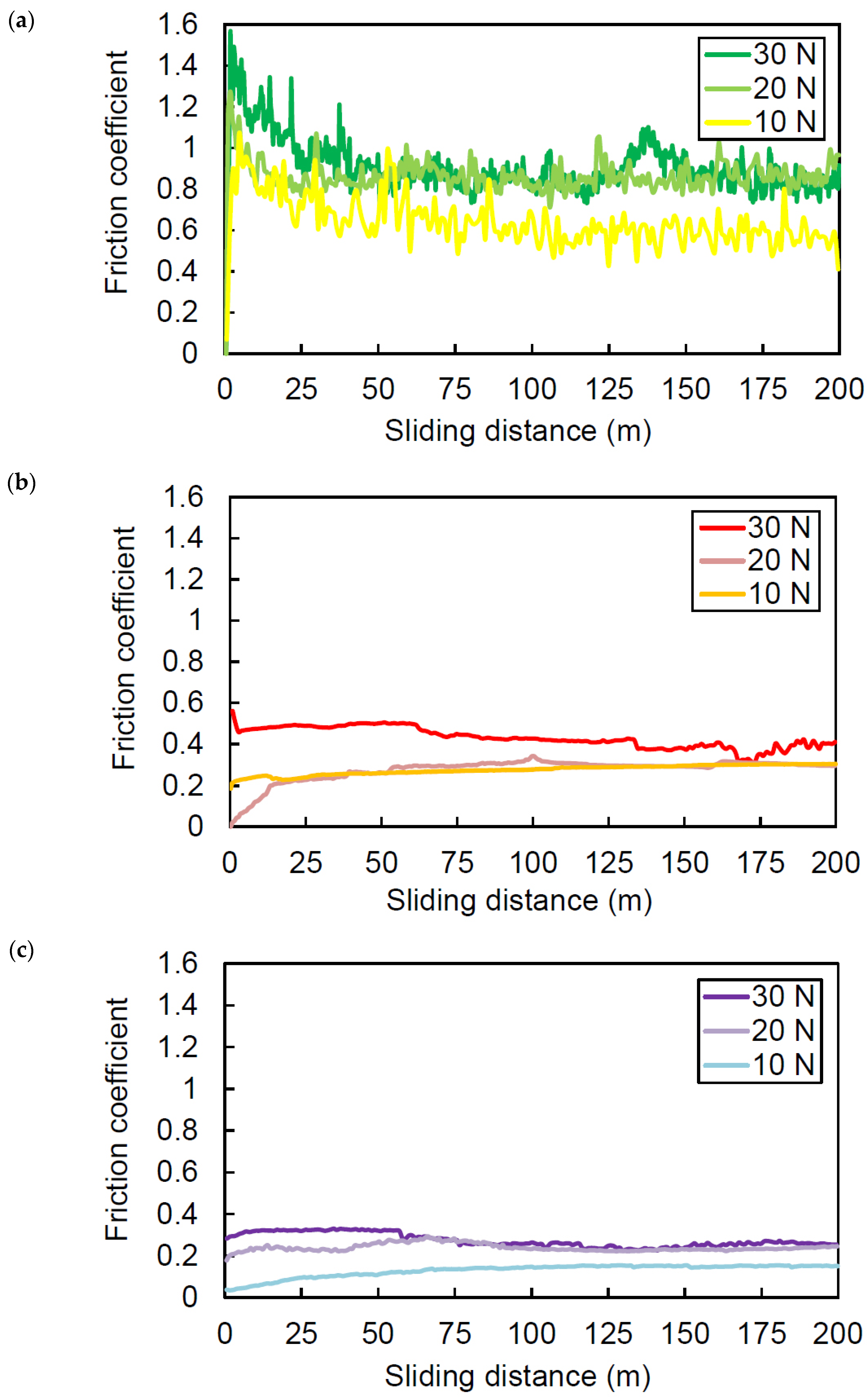
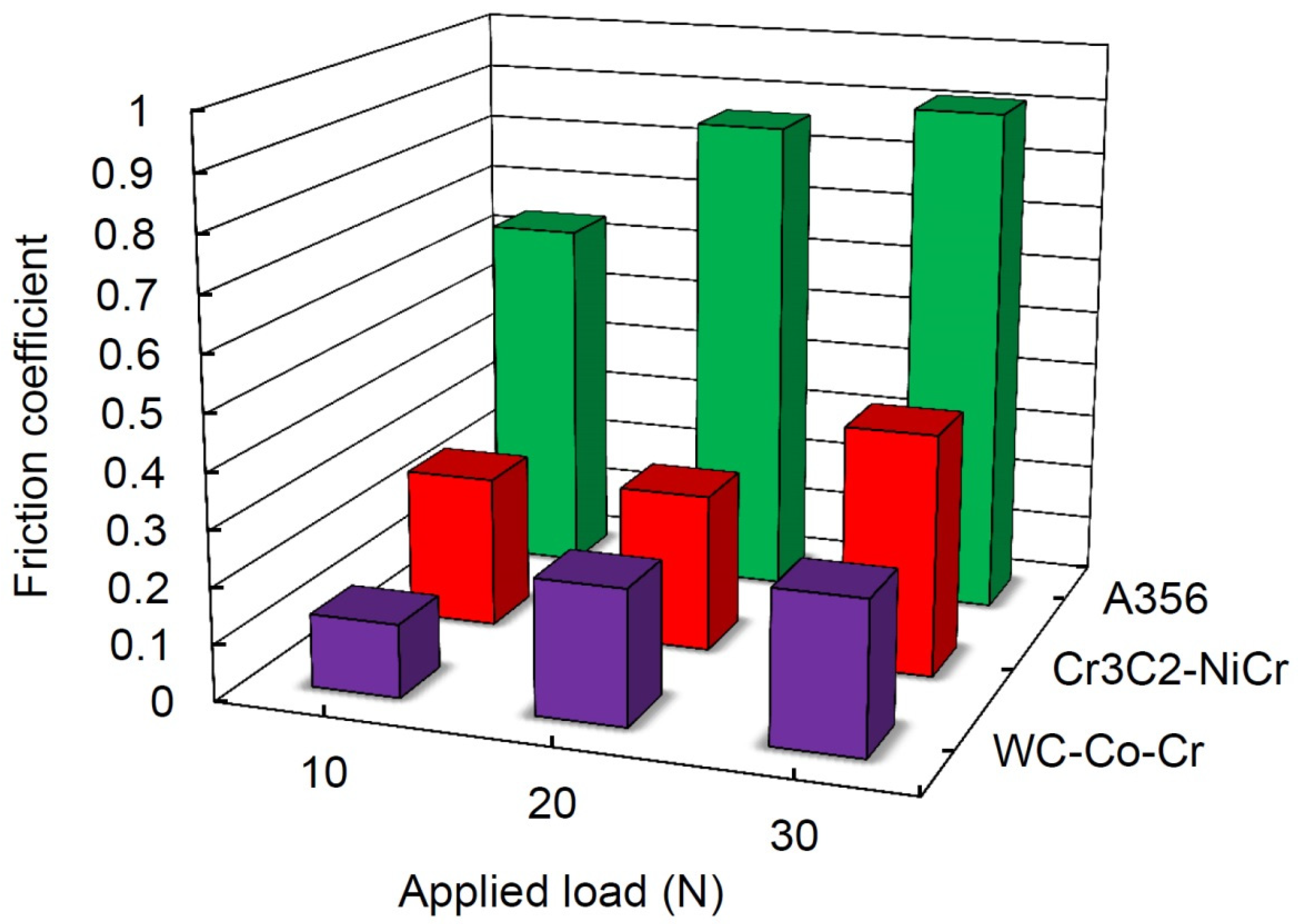
3.3.2. Friction Coefficient

Friction coefficient variations as a function of sliding distance under different applied loads are presented in Figure 9. As shown in Figure 9a, high fluctuations in the friction curves of the A356 substrate are obvious. Moreover, friction coefficient values are more than 1 in some locations, especially at high applied loads which can indicate that moreover abrasive wear, there is the adhesive mechanism. In contrast, friction coefficients of coatings especially in the WC-Co-Cr system show more uniform variations without significant fluctuations (Figure 9b,c).
The average friction coefficients of the A356 substrate and coatings after 200 m sliding distance under different applied loads are compared in Figure 10. The average friction coefficient of the A356 substrate, Cr3C2-NiCr, and WC-Co-Cr coatings under 10 N applied load was about o.64, 0.27, and 0.13, respectively. This indicates about 58 and 80% reduction in the friction coefficients by depositing Cr3C2-NiCr and WC-Co-Cr coatings, respectively. Higher resistance against adhesion in hard materials resulted in lower friction coefficients [38]. As reported by other researchers [39,40,41], the formation of lubricating oxides such as CoWO4 and WO3 on the surface may be led to the reduced friction coefficient of WC-Co-Cr coating.
Moreover, the friction coefficient variations with applied load show the same trend as those of the mass loss and wear rate. The low variations of friction coefficient in the range of 0.20–0.25 with increasing applied load from 2 N to 20 N were also observed in the case of NiCoCrAlYTa HVOF coating on 316L stainless steel substrate [31].

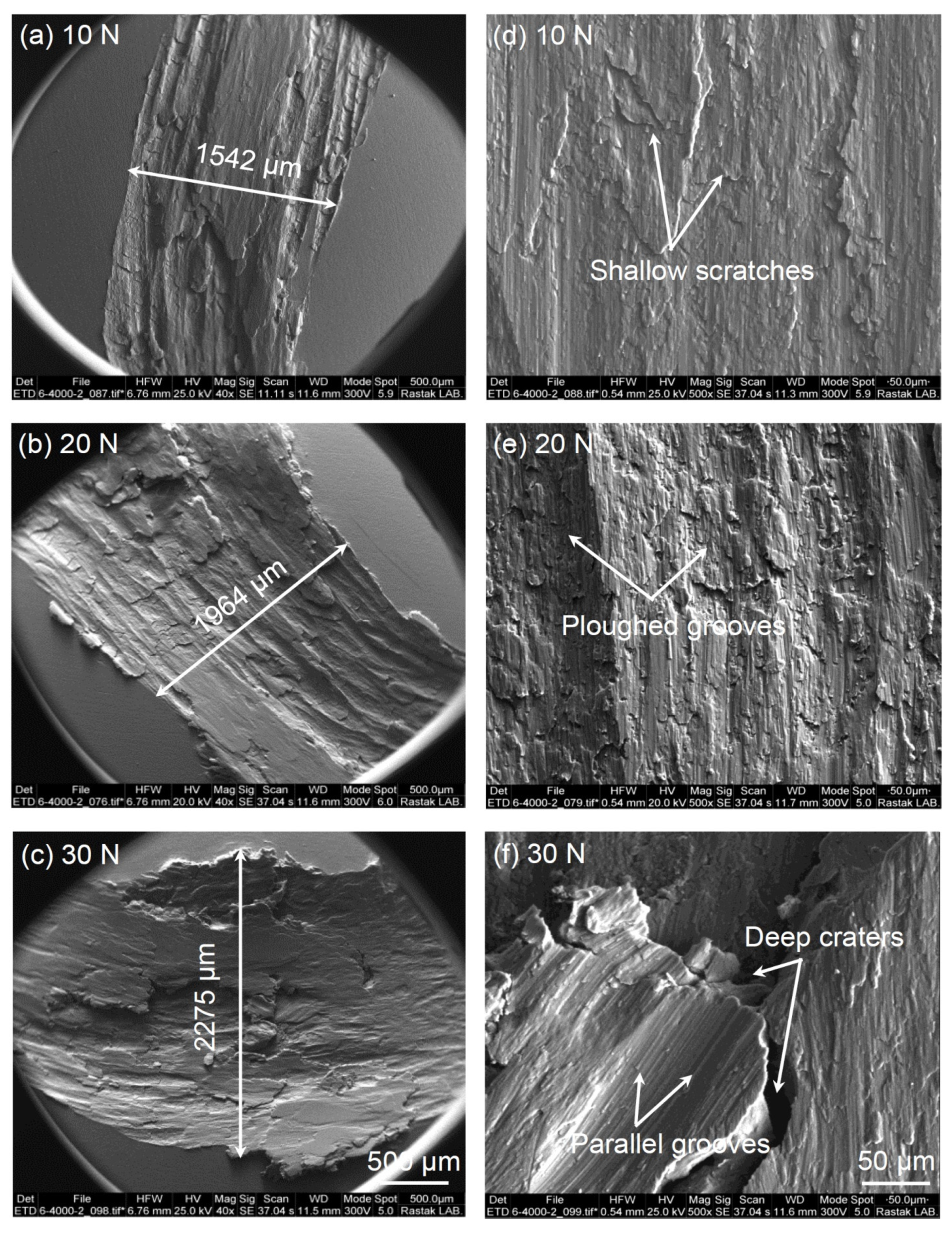
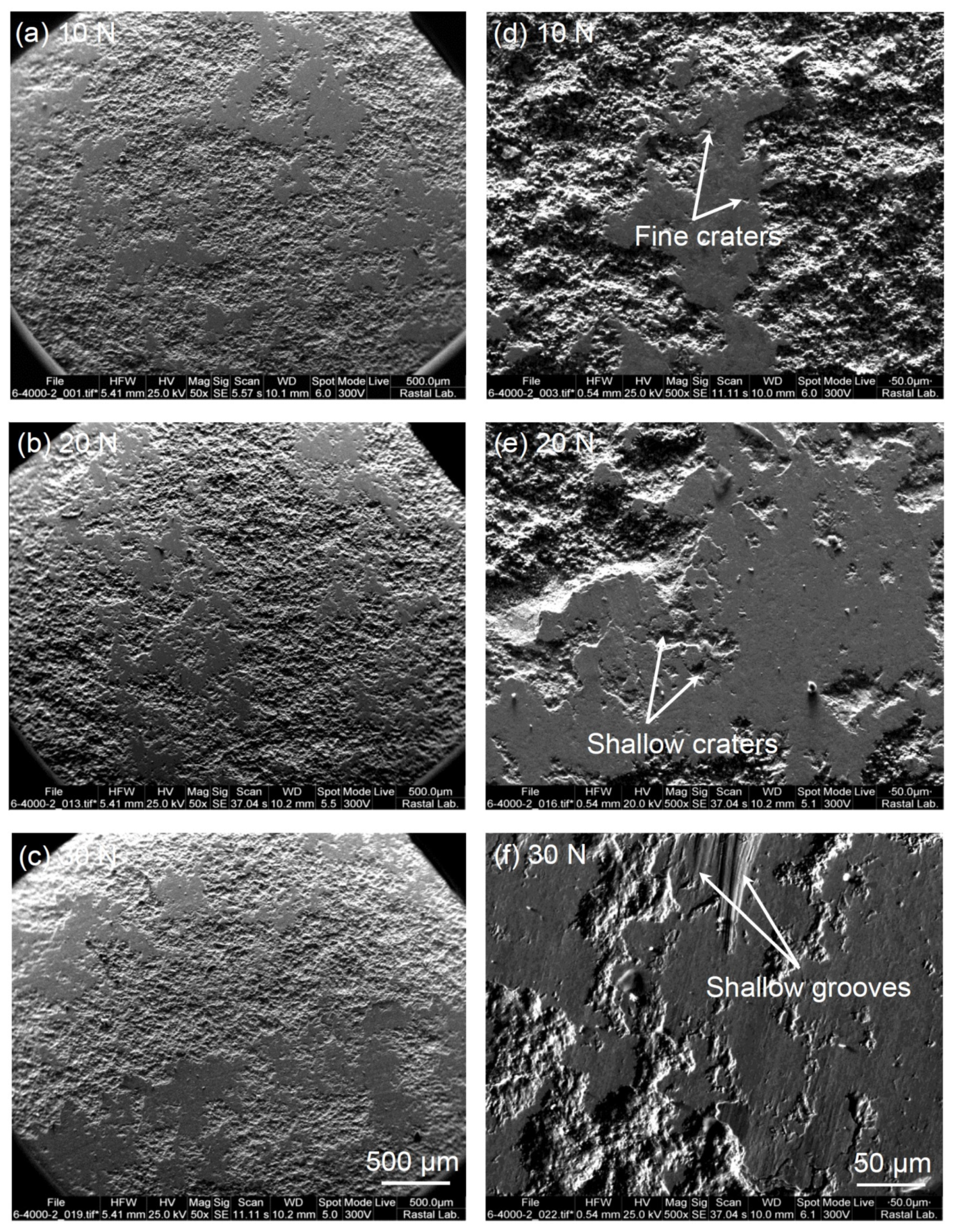
3.3.3. Wear Mechanism

The predominant wear mechanism determines through the investigations of the worn surface morphology. Figure 11, Figure 12 and Figure 13 illustrate worn surfaces of A356 alloy, Cr3C2-NiCr, and WC-Co-Cr coatings under different applied loads after 200 m sliding at low and high magnification. As shown in Figure 11a–c, the depth and width of wear tracks on A356 substrate are significantly increased with increasing applied load. This means topmost layers of the substrate was considerably removed. In contrast, except some fine and shallow craters no evidence of wear tracks can be seen on the surface of coatings (Figure 12a–c and Figure 13a–c). As these pictures show, there are no significant changes on the worn surfaces of the coatings under different applied loads. Moreover, the extent of wear in the A356 substrate is greater than that of the WC-Co-Cr coating, and this is in agreement with the results of mass loss, wear rate, and friction coefficient curves.
Considering Figure 11d–f, the flow of metal, shallow scratches, parallel and plowed grooves, and deep craters are special evidence on the uncoated A356 worn surface which intensify by increasing applied load. During the sliding wear test, as the hardness of the uncoated A356 in comparison with the counter face is lower, then a large mass loss occurs due to extensive plastic deformation, penetration, and cutting by the ball [33]. Therefore, it could be said that the uncoated A356 substrate undergoes the abrasive wear as the predominant wear mechanisms. Generally, harsh wear of A356 alloy due to its low hardness is common in the abrasive wear [42]. In addition, deep investigation of the friction coefficient variations in the A356 alloy shows values of more than 1 in some region, especially at high applied loads (Figure 9a), and from the existence of deep craters on the worn surfaces, it may be elucidated that the adhesive mechanism is another wear mode. This can be well supported by the close study of the ball after the wear test. As presented in Figure 14, the adhesion of the A356 substrate to the ball is obvious. Figure 12d–f and Figure 13d–f show that no evidence of metal flow and deep craters and scratches can be observed on the worn surface of the coatings. There are special characteristics such as fine and shallow craters and grooves in the SEM micrographs of the coatings that do not significantly vary with increasing the applied load. These indicate that the main wear modes in coatings are abrasive micro scratching and micro grooving [35].
The elemental EDS analysis results on the surface of Cr3C2-NiCr and WC-Co-Cr coatings after wearing under different applied loads are given in Figure 15 and Figure 16, respectively. It is worthwhile noting that with increasing the normal load during sliding, the higher frictional heat produces. The increased frictional heat can result in the higher oxidation of the surface during sliding. As can be seen, the intensity of the O element in the EDS results has a slight relationship with the normal load. In other words, increasing the normal load has increased the oxidation of the surface. Accordingly, the formation of a transfer film presumed to be a consequence of the reaction between the Cr (or Ni) and WC (or Co) elements in the Cr3C2-NiCr and WC-Co-Cr coatings with the oxygen [39,43]. The transfer film development through reducing the contact between ball and sample can cause the wear resistance of the coating. Furthermore, remaining the load-bearing capacity of the coating even at high applied loads can be correlated to the formation of the transfer film. The presence of zirconia in the EDS spectra and increasing its intensity by increasing the applied load can support this fact.

3.4. Corrosion Performance

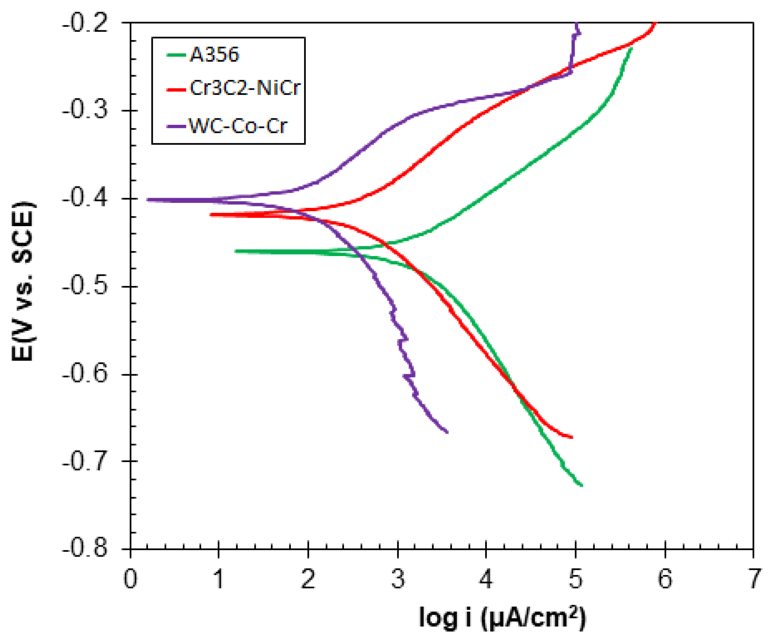
3.4.1. Polarization Test Analysis

To study the thermodynamics and kinetics of corrosion reactions in different systems, the polarization test is a useful tool. In Figure 17, to determine the corrosion mechanism of the studied samples, polarization tests have been performed.
To extract the electrochemical parameters, the TAFEL region of the cathodic and anodic branches was extrapolated and the collision point of these two lines is used for identifying the corrosion current density (icorr) and the corrosion potential (Ecorr). Moreover, the results have been reported in Table 3.
In Table 3, the βa and βc are respectively the slopes of the anodic and cathodic branches. Moreover, the polarization resistance (Rp) is obtained from the following equation:
Rp = (βc × βa)/(2.3031 × icorr × (βc + βa))
According to Table 3, the corrosion current density of the WC-Co-Cr coating is the lowest. Therefore, according to the direct relationship of corrosion current density with the corrosion rate and its inverse relationship with corrosion resistance, it can be concluded that the corrosion rate of this sample is lower than those of other samples and its corrosion resistance is the lowest. Compared with Cr3C2-NiCr, it seems that the WC-Co-Cr coating has a more resistant phase, and also more uniform coating can be been seen in microscopic images. It can be also seen that the A356 sample had the highest corrosion current density (highest corrosion rate) and the lowest polarization resistance.

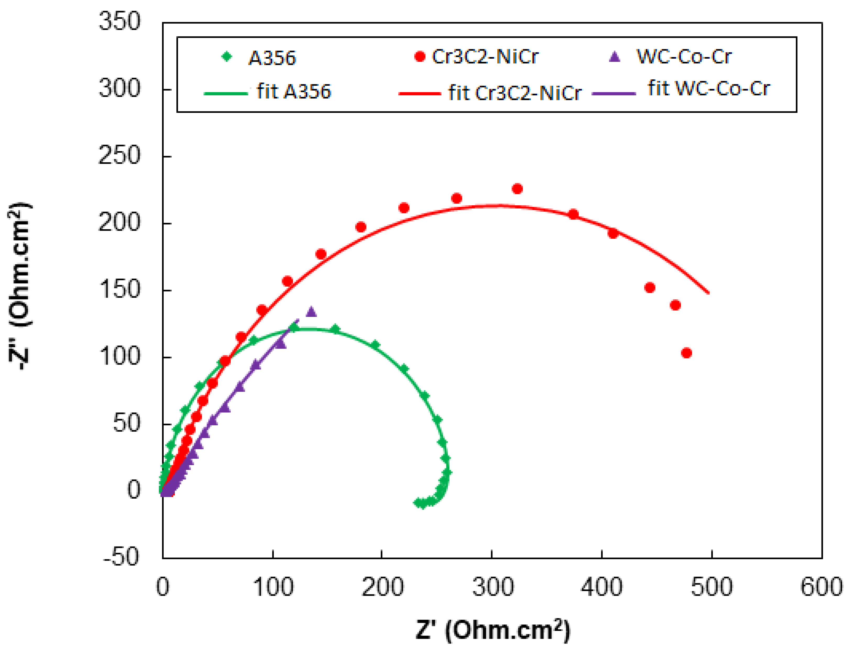
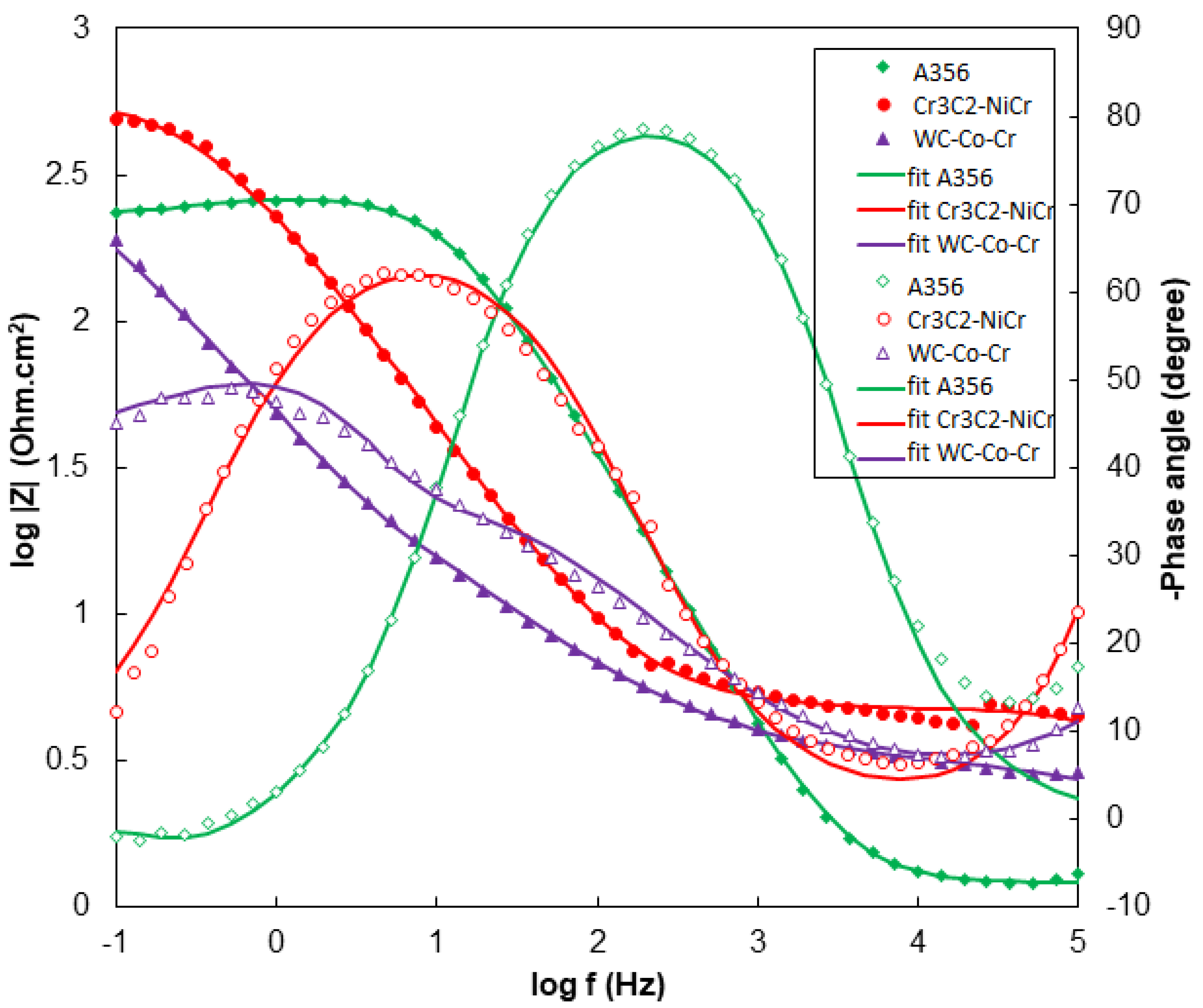
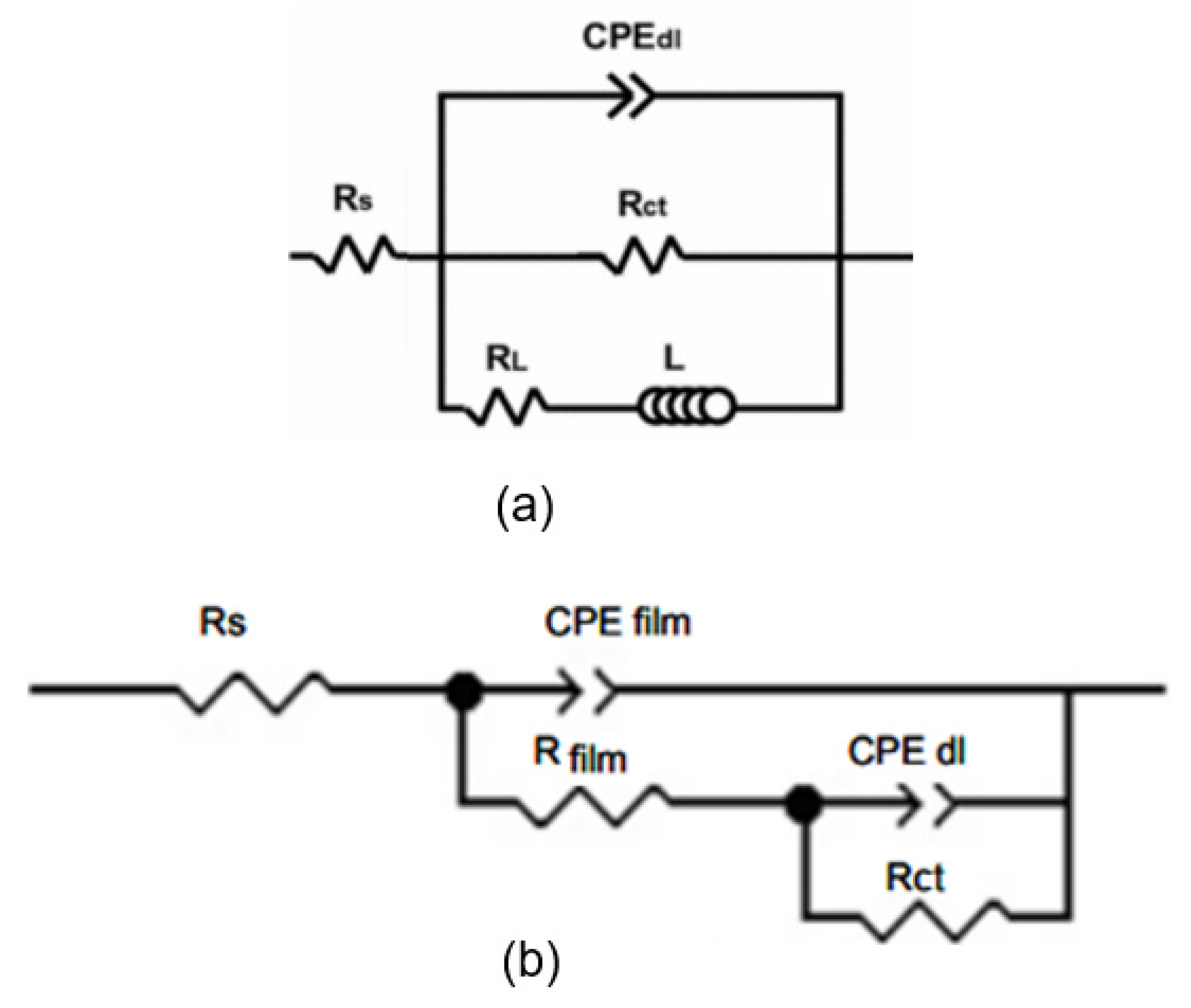
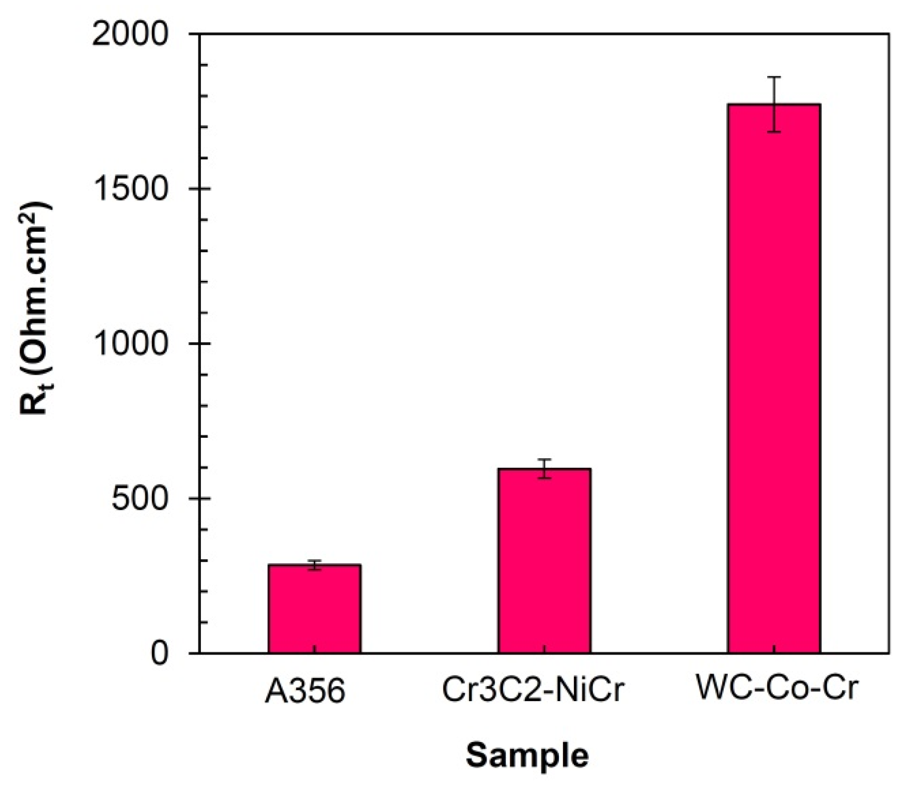
3.4.2. EIS Test Analysis

In general, each Nyquist curve is composed of semicircles or embedded semicircles in each other in which the total diameter of these semicircles indicates the corrosion resistance of the system. According to Figure 18, among the studied samples, it is clear that the A356 base sample has a smaller semicircle diameter and therefore, it has the lowest corrosion resistance. Between the WC-Co-Cr and Cr3C2-NiCr coatings, WC-Co-Cr has an incomplete semicircle, which requires a lower frequency minimum to complete this semicircle. However, along this semicircle, the diameter of the semicircle in the WC-Co-Cr sample appears to be larger than that of Cr3C2-NiCr. One of the other useful information of the EIS test is Bode curves. In Figure 19, the Bode-impedance modulus (√ (Z’2 + Z”2) = |Z|) and Bode-phase angle (Arctan (Z”/Z’)) curves for the samples are presented. These curves illustrated the frequency values rather than Nyquist plot.
It has been demonstrated that if the behavior of the system has reached a resistance state (parallel line of the horizontal axis), the total resistance of the system is the impedance at the lowest frequency of the Bode-modulus curves. As can be seen in the Bode-modulus impedance curves in Figure 19, the WC-Co-Cr coating at frequencies 10−1 still had a capacitive behavior, and the minimum frequency had to be turned to smaller values for achieving the resistance behavior. In fact, the closer value of the phase angle to 90 degrees indicates the more capacitive behavior and the decrease of this value towards zero proves the resistance behavior. However, the total resistance of the A356 substrate is lower than that of WC-Co-Cr and Cr3C2-NiCr coatings, which is similar to the obtained results from the Nyquist curves. As can be seen, the A356 sample is at a higher phase angle than the other two samples that illustrates a more capacitive behavior. This can be due to the formation of an oxide layer on the surface of the aluminum sample. On the other hand, the sample with WC-Co-Cr coating has a lower phase angle and higher corrosion resistance. The presence of an induction loop in the low-frequency Nyquist curve in the base sample can be related to the adsorption and desorption of corrosion products on the electrode surface. The use of equivalent circuits to analyze impedance tests is well-known to investigate the mechanism of corrosion. Figure 20 shows the equivalent circuits used for electrochemical modeling.
In the shown equivalent circuits in Figure 20, Rs is the solution resistance, Rfilm and CPEfilm are, respectively, the resistance and capacity of the constant phase element (CPE) of the coating. Moreover, Rct and CPEdl are the charge transfer resistance and capacity of the CPE of the double-layer, respectively. Moreover, L and RL are the inductor element and the resistance of the inductor element, respectively. In these circuits, a CPE is used instead of the ideal capacitor. According to this fact of the formed double-layer plates between the electrode surface and the electrolyte are not exactly parallel and also the electrode plate is rough and heterogeneous, the CPE is used instead of the ideal capacitor. Capacitor impedance is equal to Z = 1/jωC and this value for CPE is equal to Z = 1/(Y0jω)n in which the C means capacitor capacity, ω is the phase, Y0 is admittance (inverse of impedance and equivalent parameter of capacitance in an ideal capacitor), and j is imaginary expressions of √ (−1). As can be seen, the difference between the two mentioned impedances is the only n, in which its value is between 0 and 1. The zero value of n corresponds to an ideal resistance while its 1 value corresponds to an ideal capacitor.
Equivalence of measured samples with electrochemical equivalent circuit was performed by ZsimpWin software (version 3.2). The results of the fit of this equivalent circuit are shown on the wind and Nyquist diagrams in Figure 18 and Figure 19. Figure 18 and Figure 19 illustrate the matching of electrochemical modeling results with the impedance test measurements. Table 4 gives the obtained results.
As described above in Table 4, n is the power corresponding to the impedance formula of the CPE. By closing the n value to 1, the surface homogeneity is increased and the CPE is closed to an ideal capacitor. On other hand, by increasing the deviation of n from 1, the surface homogeneity decreased. It has been stated that total resistance, which has an adverse relationship with corrosion rate, can be obtained by summation of the charge transfer resistance and surface layer resistance (coating). Therefore, in Table 4, the total resistance (Rt) of the samples has been reported, and also it has been reported for studied samples by bar graphs in Figure 21.
According to Figure 21, it can be seen that WC-Co-Cr coating had respectively the highest corrosion resistance and the lowest corrosion rate, confirming the archived results from the Bode and Nyquist curves.

4. Conclusions

This study has investigated the Cr3C2-NiCr and WC-Co-Cr coatings deposited on A356 aluminum alloy substrate by the HVOF technique in terms of microstructure, microhardness, and tribological behavior. The following conclusions can be drawn:
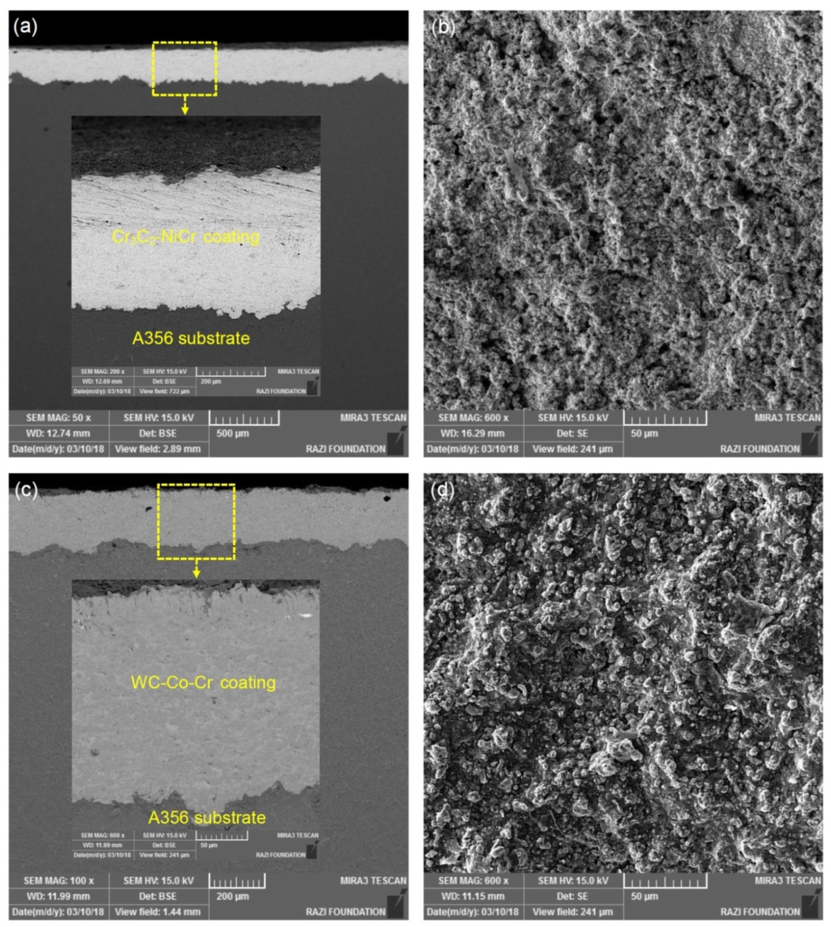
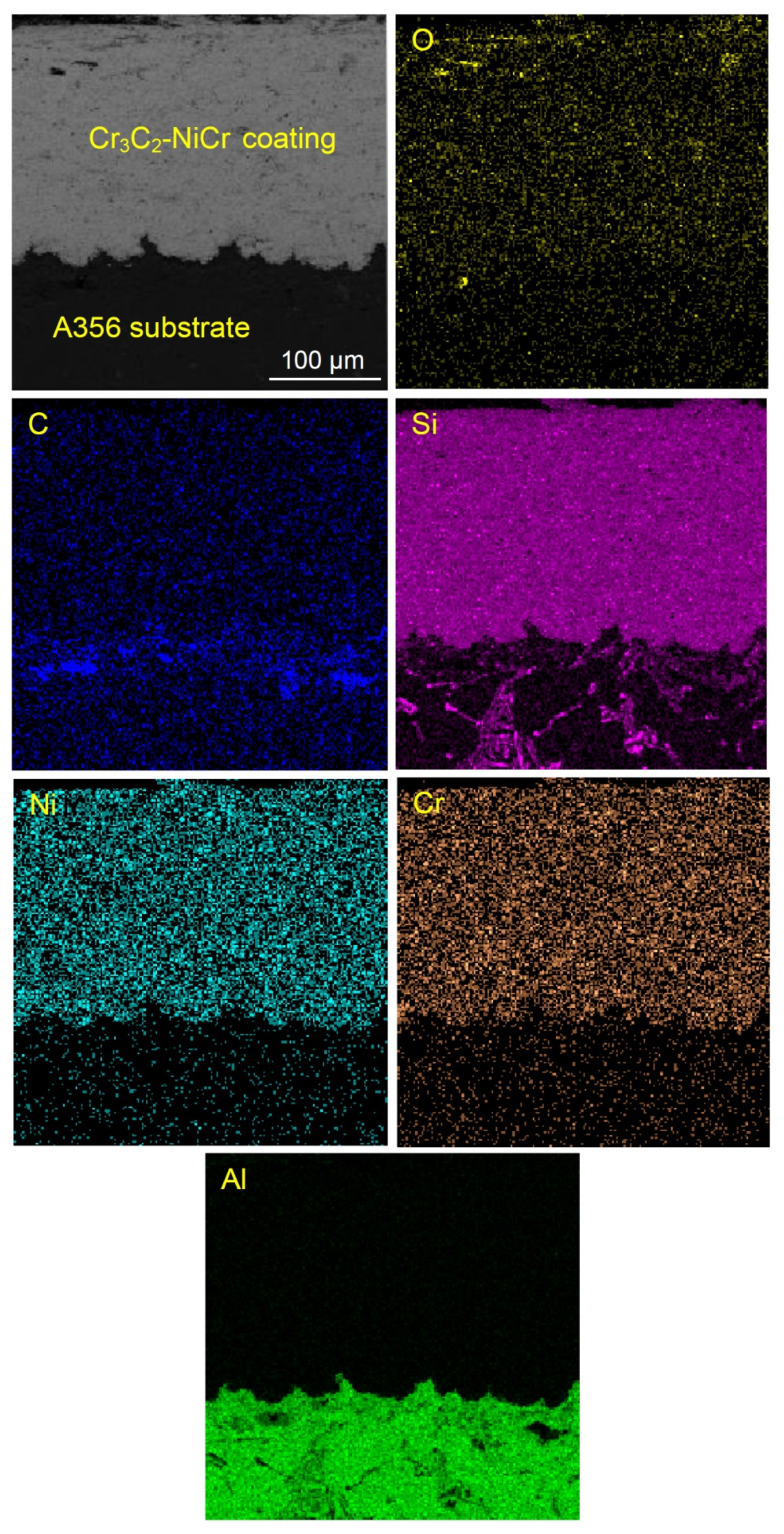
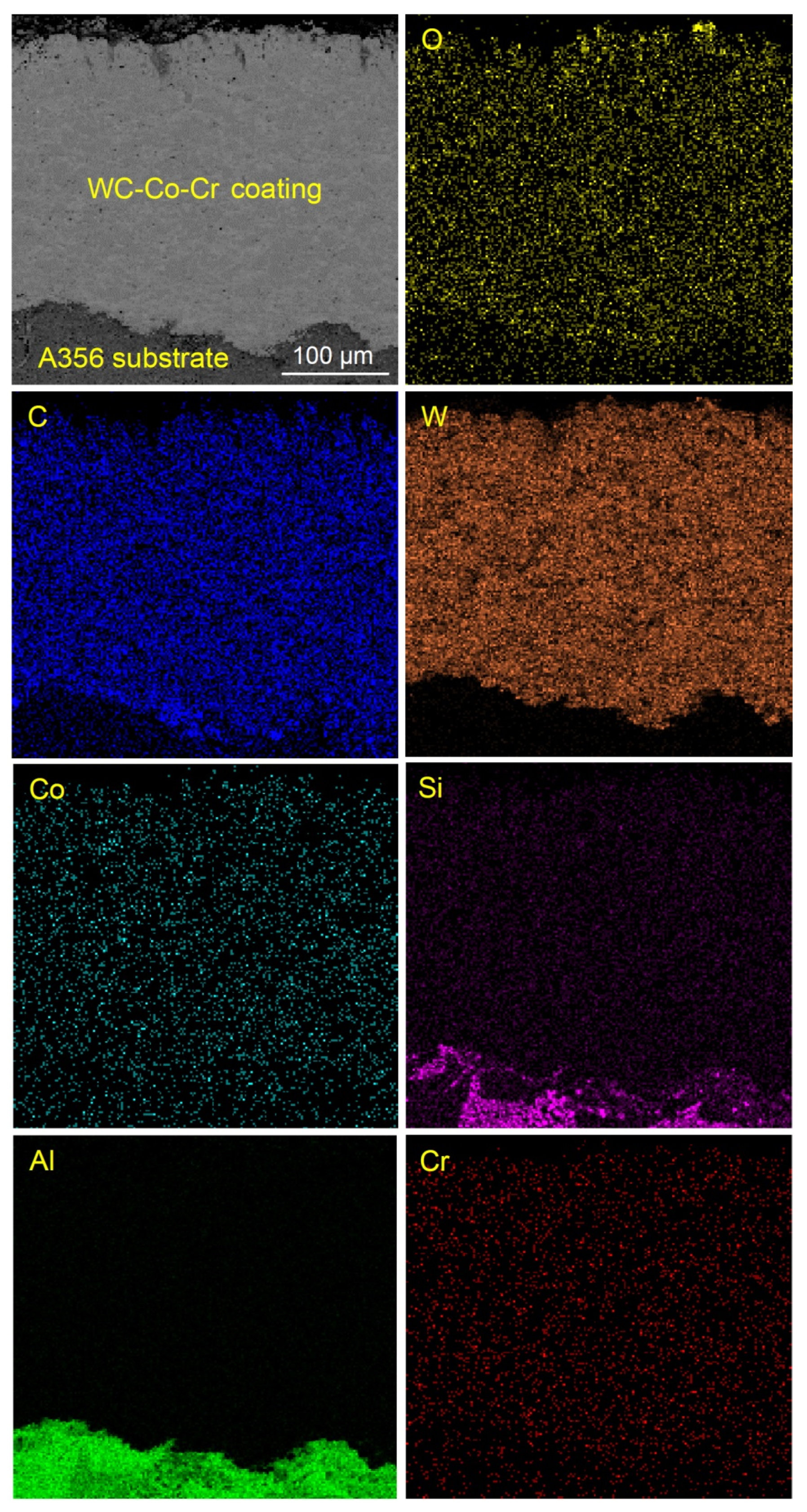
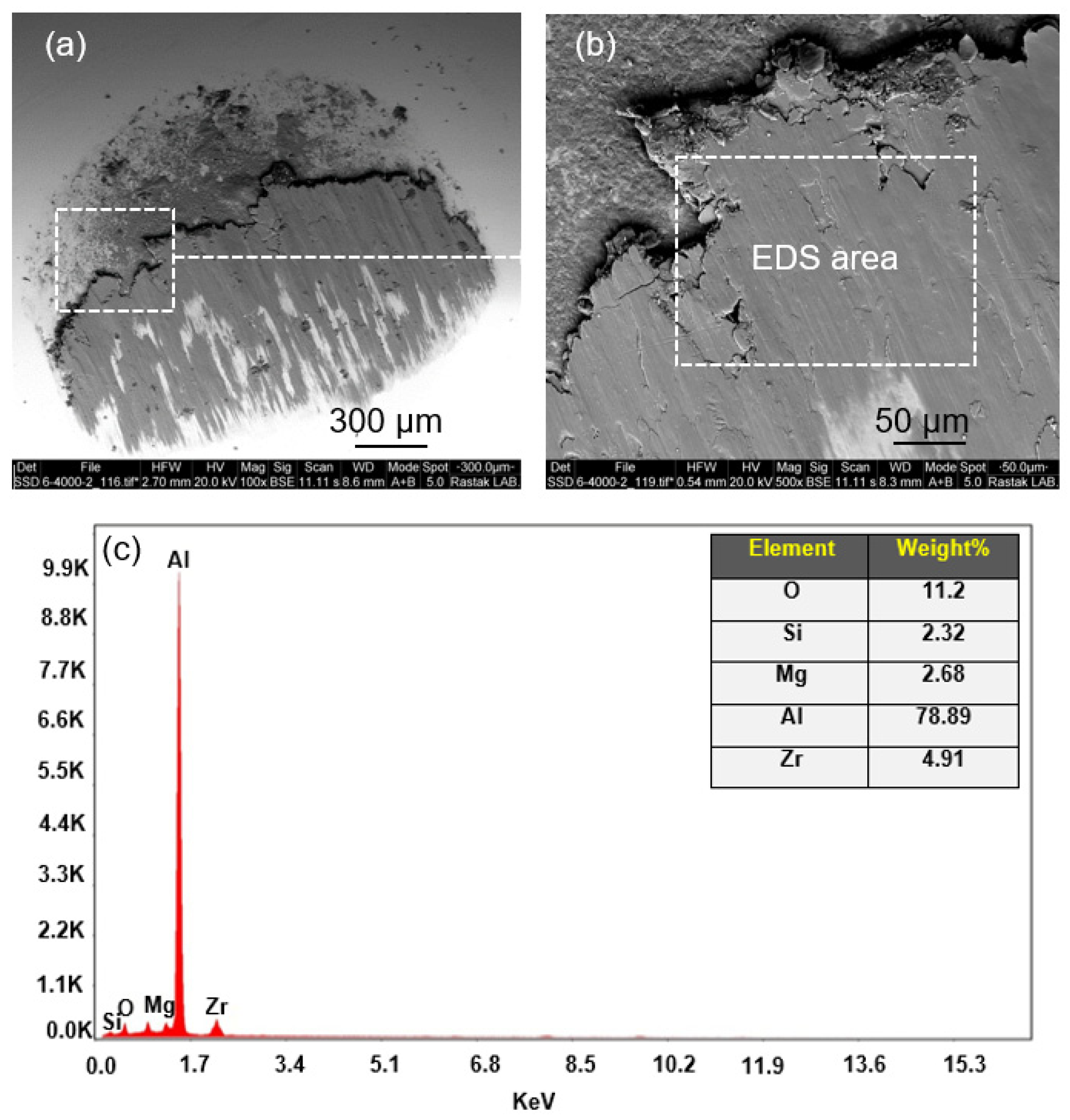
  • The coatings with an average thickness of about 250 μm were developed on the A356 substrate by 10 passes of HVOF spraying. Strong bonding between the coatings and substrate was correlated to the combination of mechanical (caused by sand blasting) and metallurgical (inter-diffusion) adhesion.
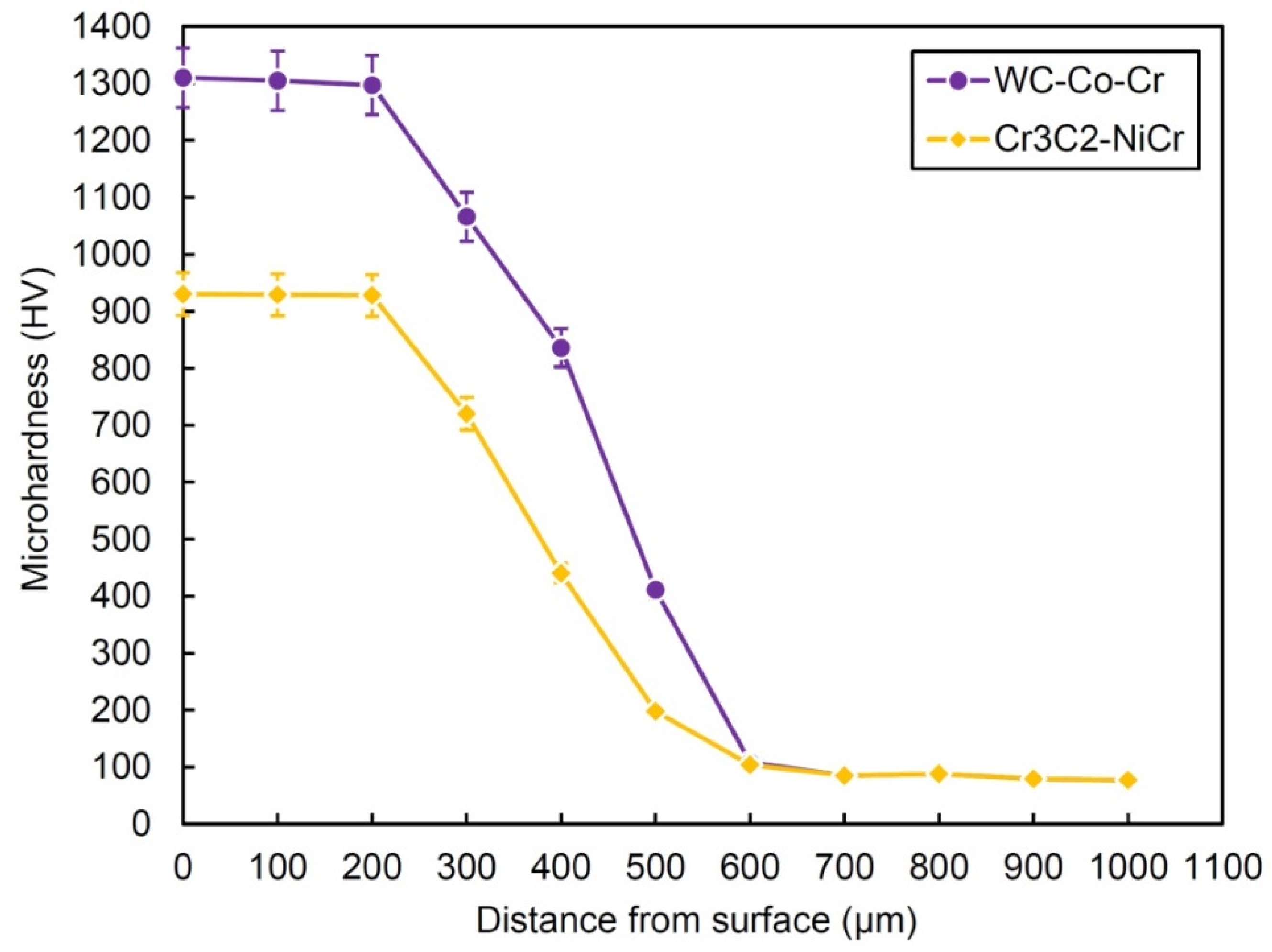
  • The microhardness of Cr3C2-NiCr and WC-Co-Cr HVOF-sprayed coatings were about 930 and 1300 HV, approximately 1100 and 1500% more than about 80 HV of the A356 substrate, respectively. The homogeneity of the coatings was concluded from the small scattering of microhardness values within the coatings layer.
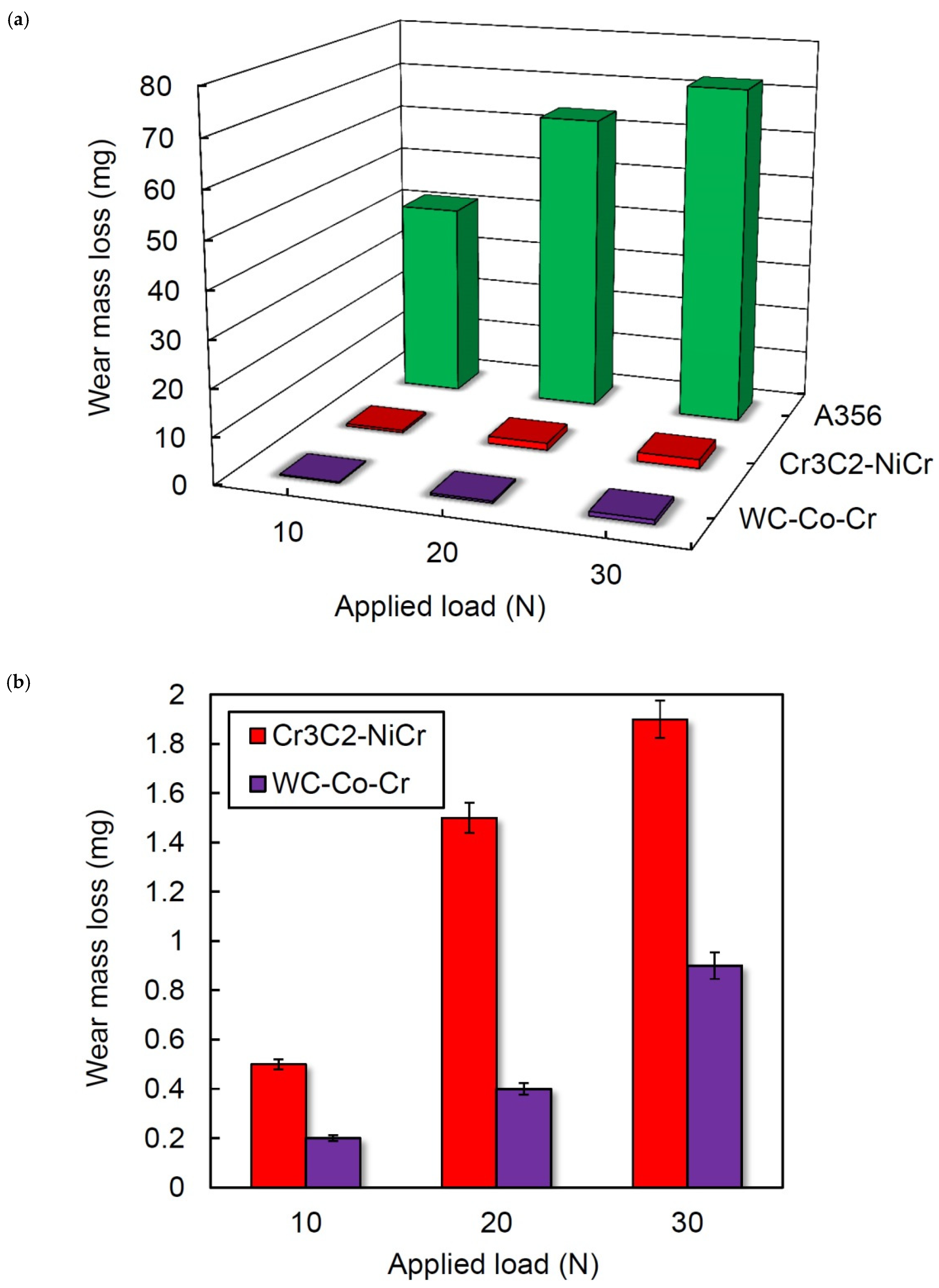
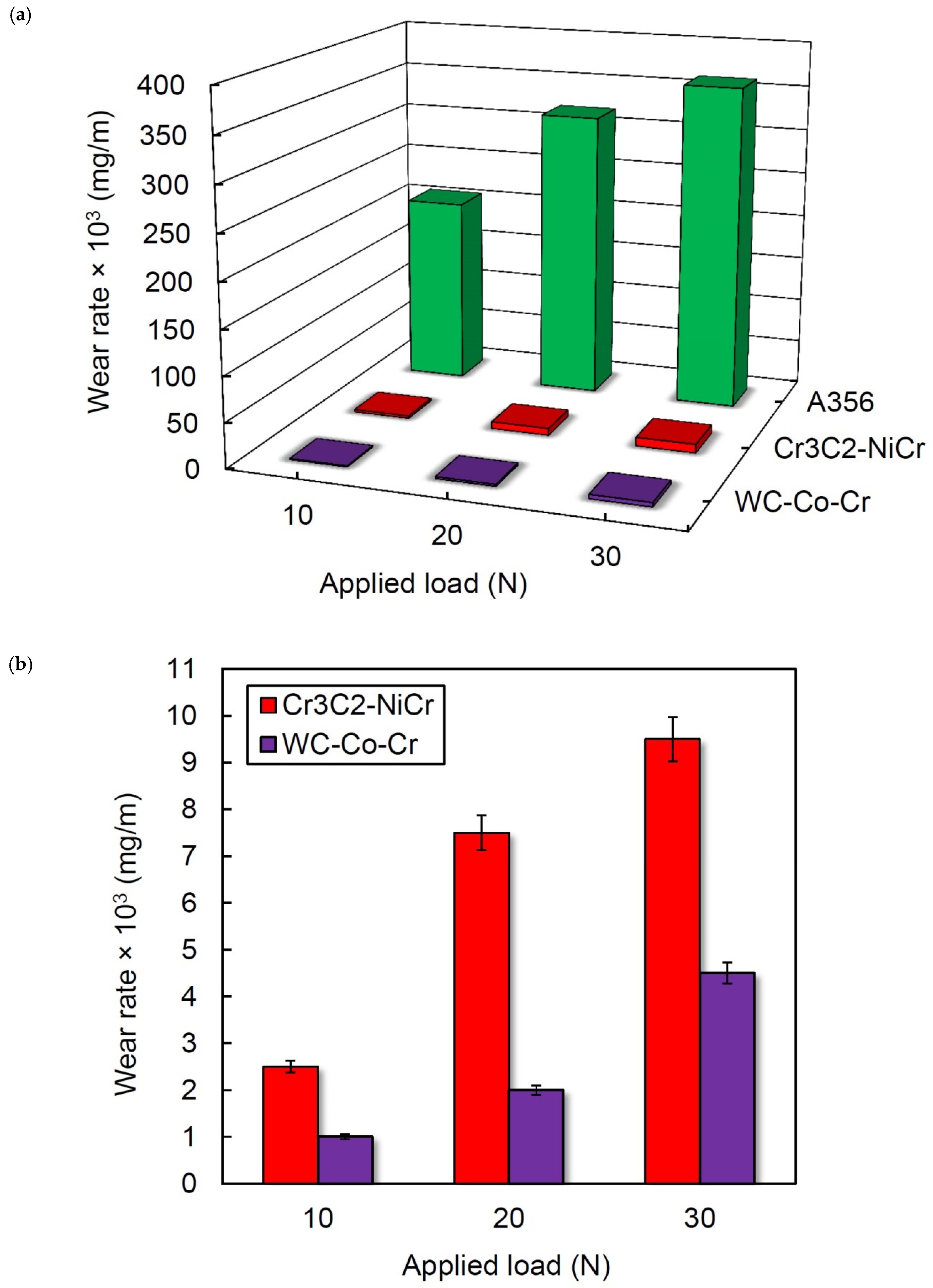
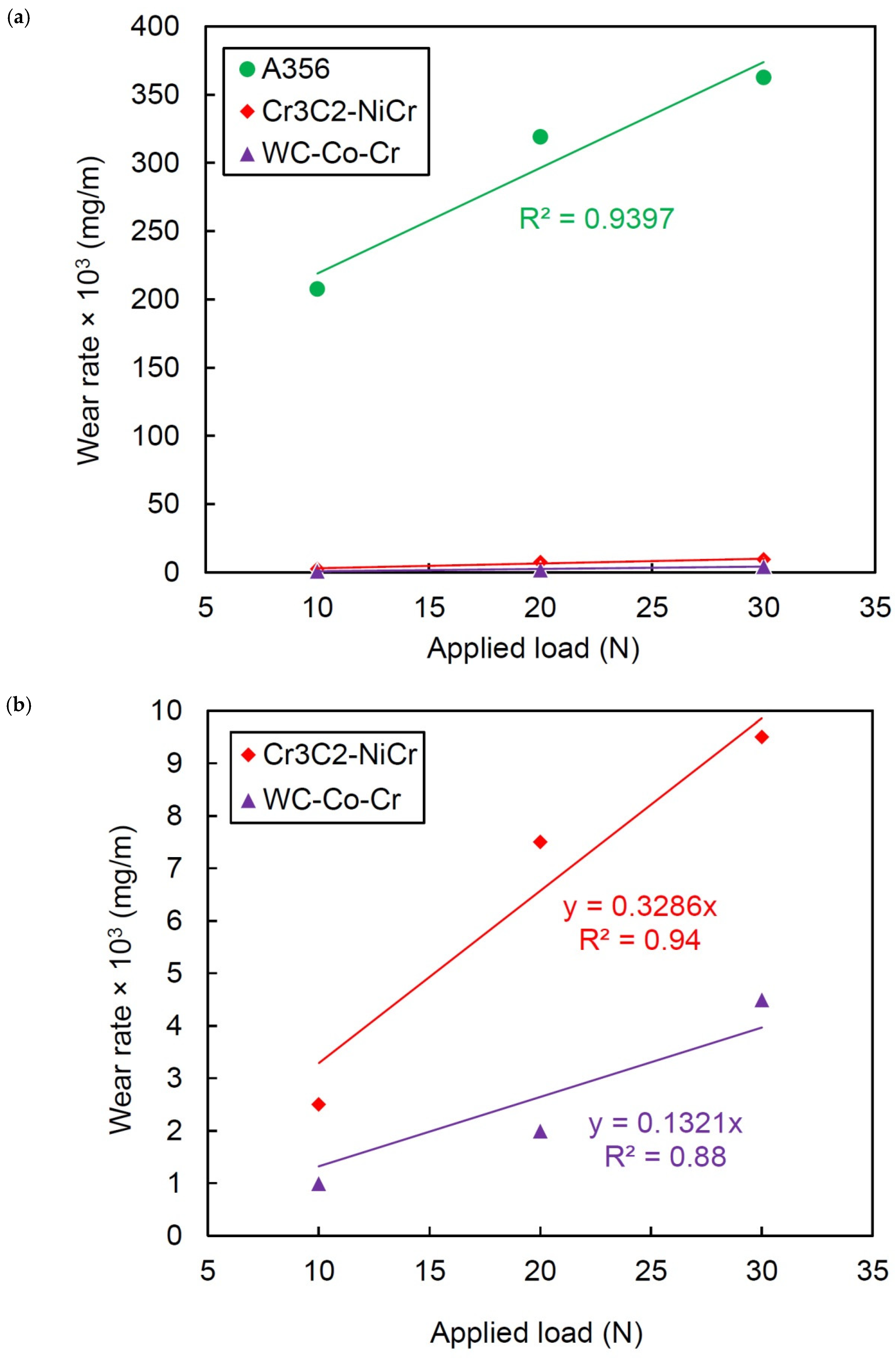
  • The mass loss and wear rate values of A356 substrate after coating with Cr3C2-NiCr were reduced by a factor of about 83, 43, and 38 times under 10, 20, and 30 N applied load, respectively. In the case of WC-Co-Cr coating, the reduction factors were about 208, 160, and 81 times. The wear characteristics of the A356 substrate progressively increased with increasing applied load. However, the mass losses and wear rate variations of the coatings were less than those of the A356 substrate.
  • The wear coefficient of the Cr3C2-NiCr coating was about 1.8 times higher than that of the WC-Co-Cr coating. This indicated the lower wear resistance of the Cr3C2-NiCr coating in comparison with the WC-Co-Cr coating.
  • The average friction coefficients of A356 substrate, Cr3C2-NiCr, and WC-Co-Cr coatings under 10 N applied load were about o.64, 0.27, and 0.13, respectively. This indicates about 58 and 80% reduction in the friction coefficients by depositing Cr3C2-NiCr and WC-Co-Cr coatings, respectively.
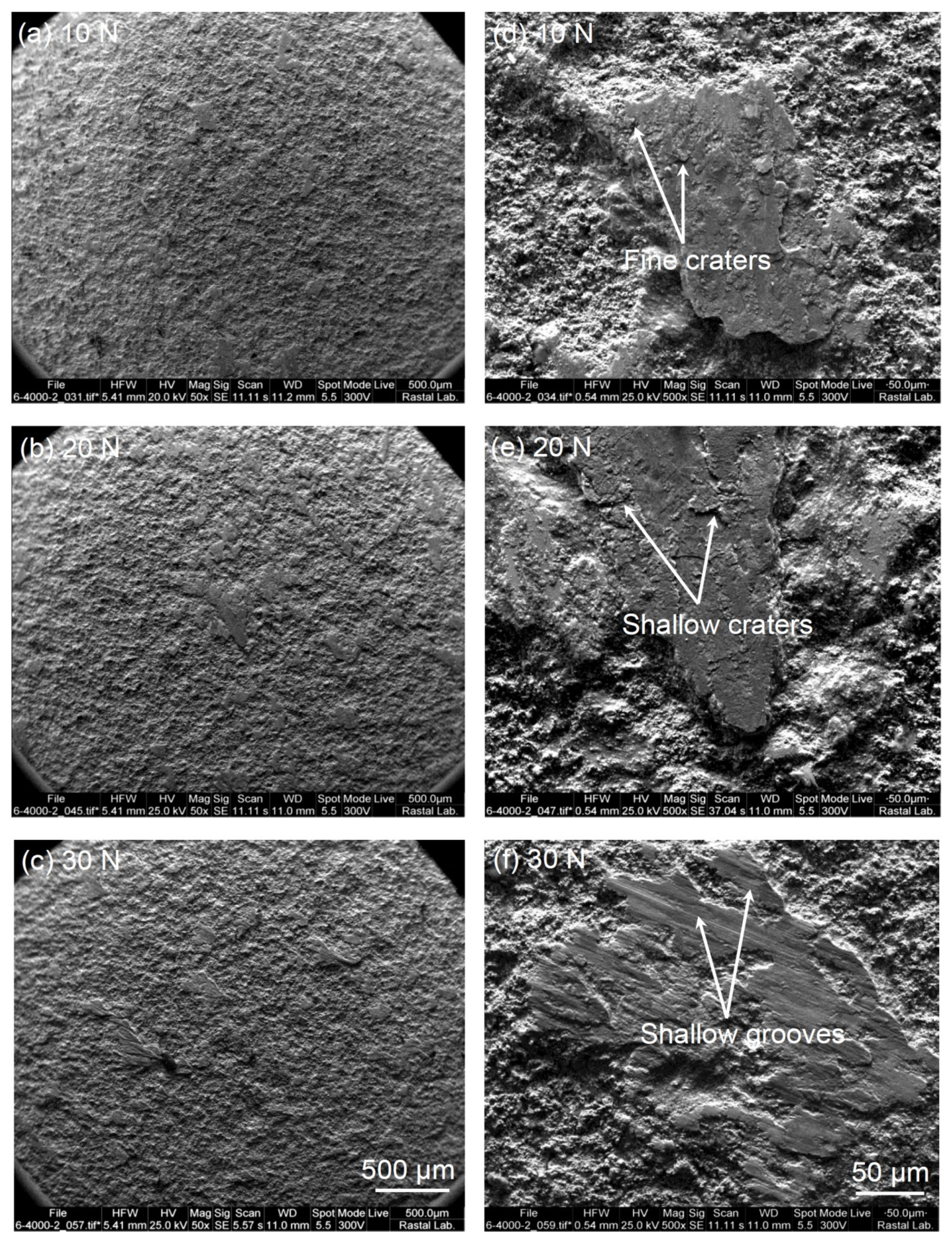
  • The SEM micrographs of worn surfaces revealed wear mechanisms for the uncoated A356 alloy was abrasive and adhesive wear, while abrasive micro grinding and micro grooving were dominant in the coatings.
  • The results of corrosion evaluation, i.e., potentiodynamic polarization, and EIS measurements show a significant corrosion performance advancement of Cr3C2-NiCr and WC-Co-Cr samples compared to the coating-free base metal. The WC-Co-Cr coating had the highest corrosion resistance and the lowest corrosion rate.

Author Contributions

Conceptualization, Y.M.; methodology, E.K.; software, M.R.; investigation, E.K.; writing—original draft preparation, Y.M. and M.R.; writing—review and editing, Y.M., M.S. and A.H.; supervision, Y.M.; All authors have read and agreed to the published version of the manuscript.

Funding

This research received no external funding.

Institutional Review Board Statement

Not applicable.

Informed Consent Statement

Not applicable.

Data Availability Statement

The raw/processed data required to reproduce these findings will be available from the corresponding author upon reasonable request.

Conflicts of Interest

The authors declare no conflict of interest.

References

  1. Polmear, I.; John, D.S.; Nie, J.F.; Qian, M. Light Alloys: Metallurgy of the Light Metals, 5th ed.; Butterworth-Heinemann: Chennai, India, 2017. [Google Scholar]
  2. Lumley, R. Fundamentals of Aluminium Metallurgy: Production, Processing and Applications; Elsevier: Amsterdam, The Netherlands, 2010. [Google Scholar]
  3. Pawlowski, L. The Science and Engineering of Thermal Spray Coatings; John Wiley & Sons: New York, NY, USA, 2008. [Google Scholar]
  4. Fang, W.; Cho, T.Y.; Yoon, J.H.; Song, K.O.; Hur, S.K.; Youn, S.J.; Chun, H.G. Processing optimization, surface properties and wear behavior of HVOF spraying WC–CrC–Ni coating. J. Mater. Process. Technol. 2009, 209, 3561–3567. [Google Scholar] [CrossRef]
  5. Celik, E.; Culha, O.; Uyulgan, B.; AkAzem, N.F.; Ozdemir, I.; Turk, A. Assessment of microstructural and mechanical properties of HVOF sprayed WC-based cermet coatings for a roller cylinder. Surf. Coat. Technol. 2006, 200, 4320–4328. [Google Scholar] [CrossRef]
  6. Straffelini, G.; Federici, M. HVOF cermet coatings to improve sliding wear resistance in engineering systems. Coatings 2020, 10, 886. [Google Scholar] [CrossRef]
  7. Sidhu, T.S.; Prakash, S.; Agarwal, R.D. Performance of high velocity oxy-fuel-sprayed coatings on a Fe-based superalloy in Na2SO4-60%V2O5 environment at 900 °C Part I: Characterization of the coatings. J. Mater. Eng. Perform. 2006, 15, 122–129. [Google Scholar] [CrossRef]
  8. Herman, H.; Sampath, S.; Mccune, R. Thermal spray: Current status and future trends. MRS Bull. 2000, 25, 17–25. [Google Scholar] [CrossRef]
  9. Souza, V.A.D.; Neville, A. Aspects of microstructure on the synergy and overall material loss of thermal spray coatings in erosion–corrosion environments. Wear 2007, 263, 339–346. [Google Scholar] [CrossRef]
  10. Lau, M.L.; Jiang, H.G.; Nuchter, W.; Lavernia, E.J. Thermal spraying of nanocrystalline Ni coatings. Phys. Status Solidi 1998, 166, 257–268. [Google Scholar] [CrossRef]
  11. Sidhu, T.S.; Prakash, S.; Agrawal, R.D. Studies on the properties of high-velocity oxy-fuel thermal spray coatings for higher temperature applications. Mater. Sci. 2005, 41, 805–821. [Google Scholar] [CrossRef]
  12. Berget, J.; Rogne, T.; Bardal, E. Erosion–corrosion properties of different WC–Co–Cr coatings deposited by the HVOF process—Influence of metallic matrix composition and spray powder size distribution. Surf. Coat. Technol. 2007, 201, 7619–7625. [Google Scholar] [CrossRef]
  13. Mazaheri, Y.; Karimzadeh, F.; Enayati, M.H. Development of Al356/Al2O3 nanocompositecoatings by high velocity oxy-fuel technique. J. Mater. Sci. Technol. 2013, 29, 813–820. [Google Scholar] [CrossRef]
  14. el Rayes, M.M.; Abdo, H.S.; Khalil, K.A. Erosion–corrosion of cermet coating. Int. J. Electrochem. Sci. 2013, 8, 1117–1137. [Google Scholar]
  15. Wang, B.Q.; Luer, K. The erosion-oxidation behaviour of HVOF Cr3C2-NiCr cermet coating. Wear 1994, 174, 177–185. [Google Scholar] [CrossRef]
  16. Roy, M.; Pauschitz, A.; Bernardi, J.; Koch, T.; Franek, F. Microstructure and mechanical properties of HVOF sprayed nanocrystalline Cr3C2-25(Ni20Cr) coating. J. Therm. Spray Technol. 2006, 15, 372–381. [Google Scholar] [CrossRef]
  17. Li, Y.; Gao, Y.; Xiao, B.; Min, T.; Yang, Y.; Ma, S.; Yie, D. The electronic, mechanical properties and theoretical hardness of chromium carbides by first-principles calculations. J. Alloys Compd. 2011, 509, 5242–5249. [Google Scholar] [CrossRef]
  18. Frawick, D.G.; Johnson, R.N. Wear and corrosion performance of metallurgical coatings in sodium. Thin Solid Films 1980, 73, 145–153. [Google Scholar] [CrossRef]
  19. Kunioshi, C.T.; Correa, O.V.; Ramanathan, L.V. High temperature oxidation and erosion-oxidation behaviour of HVOF sprayed Ni-20Cr, WC-20Cr-7Ni and Cr3C2-Ni-20Cr coatings. Surf. Eng. 2006, 22, 121–127. [Google Scholar] [CrossRef]
  20. Reddy, N.C.; Kumar, B.S.A.; Reddappa, H.N.; Ramesh, M.R.; Koppad, P.G.; Kord, S. HVOF sprayed Ni3Ti and Ni3Ti+(Cr3C2+20NiCr) coatings: Microstructure, microhardness and oxidation behavior. J. Alloys Compd. 2018, 736, 236–245. [Google Scholar] [CrossRef]
  21. Han, T.; Deng, C.; Zhang, X.; Liu, Q. A model of splats deposition state and wear resistance of WC-10Co4Cr coating. Ceram. Int. 2018, 44, 4230–4236. [Google Scholar] [CrossRef]
  22. Gibbons, G.J.; Hansell, R.G. Down-selection and optimization of thermal-sprayed coatings for aluminum mould tool protection and upgrade. J. Therm. Spray Technol. 2006, 15, 340–347. [Google Scholar] [CrossRef]
  23. Barletta, M.; Bolelli, G.; Bonferroni, B.; Lusvarghi, L. Wear and corrosion behavior of HVOF-sprayed WC-CoCr coatings on Al alloys. J. Therm. Spray Technol. 2010, 19, 358–367. [Google Scholar] [CrossRef]
  24. Wood, R.J.K. Erosion–corrosion interactions and their effect on marine and offshore materials. Wear 2006, 261, 1012–1023. [Google Scholar] [CrossRef]
  25. Mazaheri, Y.; Malmir, R.; Jalilvand, M.M.; Sheikhi, M.; Heidarpour, A. Mechanical properties and tribological performance of A356/Cr3C2-NiCr surface composite developed by high-velocity oxy-fuel and post friction stir processing treatment. Surf. Interfaces 2022, 28, 101627. [Google Scholar] [CrossRef]
  26. Zhang, Z.; Lim, S.H.; Chai, J.; Lai, D.M.Y.; Lim, P.C.; Kok, A.; Cheong, H.; Wang, S.; Jin, H.; Pan, J. Kerosene-fuelled high velocity oxy-fuel (HVOF) spray of Ti2AlC MAX phase powders. J. Alloys Compd. 2018, 735, 377–385. [Google Scholar] [CrossRef]
  27. Ghosh, G.; Sidpara, A.; Bandyopadhyay, P.P. High efficiency chemical assisted nanofinishing of HVOF sprayed WC-Co coating. Surf. Coat. Technol. 2018, 334, 204–214. [Google Scholar]
  28. Kaushal, G.; Kaur, N.B.N.; Singh, H.; Prakash, S. Comparative high-temperature corrosion behavior of Ni-20Cr coatings on T22 boiler steel produced by HVOF, D-gun, and cold spraying. Metall. Mater. Trans. A 2014, 45, 395–410. [Google Scholar]
  29. Han, Y.; Zhu, Z.; Zhang, B.; Chu, Y.; Zhang, Y.; Fan, J. Effects of process parameters of vacuum pre-oxidation on the microstructural evolution of CoCrAlY coating deposited by HVOF. J. Alloys Compd. 2018, 735, 547–559. [Google Scholar] [CrossRef]
  30. Bolelli, G.; Lusvarghi, L.; Manfredini, T.; Matikainen, V.; Rigon, P.S.R.; Vuoristo, P. Tribology of FeVCrC coatings deposited by HVOF and HVAF thermal spray processes. Wear 2018, 394–395, 113–133. [Google Scholar] [CrossRef]
  31. Liu, X.Z.X.; An, Y.; Hou, G.; Li, S.; Deng, W.; Zhou, J.C.H.; Chen, J. Effects of loads on corrosion-wear synergism of NiCoCrAlYTa coating in artificial seawater. Tribol. Int. 2018, 118, 421–431. [Google Scholar]
  32. Lamana, M.S.; Pukasiewicz, A.G.M.; Sampath, S. Influence of cobalt content and HVOF deposition process on the cavitation erosion resistance of WC-Co coatings. Wear 2018, 398–399, 209–219. [Google Scholar] [CrossRef]
  33. Matikainen, V.; Bolelli, G.; Koivuluoto, H.; Sassatelli, P.; Lusvarghi, L.; Vuoristo, P. Sliding wear behaviour of HVOF and HVAF sprayed Cr3C2-based coatings. Wear 2017, 388–389, 57–71. [Google Scholar] [CrossRef]
  34. Cheng, D.; Xu, Q.; Lavernia, E.J.; Trapaga, G. The Effect of particle size and morphology on the In-flight behavior of particles during High-Velocity Oxy-Fuel thermal spraying. Metall. Mater. Trans. B 2001, 32, 525–535. [Google Scholar] [CrossRef]
  35. Bolelli, G.; Berger, L.-M.; Börner, T.; Koivuluoto, H.; Matikainen, V.; Lusvarghi, L.; Lyphout, C.; Markocsan, N.; Nylén, P.; Sassatelli, P.; et al. Sliding and abrasive wear behaviour of HVOF- and HVAF-sprayed Cr3C2-NiCr hardmetal coatings. Wear 2016, 358–359, 32–50. [Google Scholar] [CrossRef]
  36. Gant, A.J.; Gee, M.G. Wear modes in slurry jet erosion of tungsten carbide hardmetals:their relationship with microstructure and mechanical properties. Int. J. Refract. Met. Hard Mater. 2015, 49, 192–202. [Google Scholar] [CrossRef]
  37. Archard, J.F. Contact and rubbing of flat surfaces. J. Appl. Phys. 1953, 24, 981–988. [Google Scholar] [CrossRef]
  38. Mokhtar, M.O. The effect of hardness on the frictional behavior of metals. Wear 1982, 78, 297–304. [Google Scholar] [CrossRef]
  39. Wang, T.; Ye, F. The elevated-temperature wear behavior evolution of HVOF sprayed tungsten carbide coatings: Respond to heat treatment. Int. J. Refract. Met. Hard Mater. 2018, 71, 92–100. [Google Scholar] [CrossRef]
  40. Geng, Z.; Hou, S.; Shi, G.; Duan, D.L.; Li, S. Tribological behaviour at various temperatures of WC-Co coatings prepared using different thermal spraying techniques. Tribol. Int. 2016, 104, 36–44. [Google Scholar] [CrossRef]
  41. Geng, Z.; Li, S.; Duan, D.L.; Liu, Y. Wear behaviour of WC-Co HVOF coatings at different temperatures in air and argon. Wear 2015, 330–331, 348–353. [Google Scholar] [CrossRef]
  42. Chen, Y.C.; Nakata, K. Evaluation of microstructure and mechanical properties in friction stir processed SKD61 tool steel. Mater. Charact. 2009, 60, 1471–1475. [Google Scholar] [CrossRef]
  43. Mi, P.; Zhao, H.; Wang, T.; Ye, F. Sliding wear behavior of HVOF sprayed WC-(nano-WC-Co) coating at elevated temperatures. Mater. Chem. Phys. 2018, 206, 1–6. [Google Scholar] [CrossRef]
Figure 1. SEM micrograph of as-received (a) Cr3C2-NiCr and (b) WC-Co-Cr powders.
Coatings 12 01408 g001
Figure 2. SEM micrographs on the cross-section (a) and surface morphology (b) of Cr3C2-NiCr coating and the cross-section (c) and surface morphology (d) of WC-Co-Cr coating.
Coatings 12 01408 g002
Figure 3. EDS elemental mapping on the cross-section of HVOF-sprayed Cr3C2-NiCr coating on A356 substrate.
Coatings 12 01408 g003
Figure 4. EDS elemental mapping on the cross-section of HVOF-sprayed WC-Co-Cr coating on A356 substrate.
Coatings 12 01408 g004
Figure 5. Microhardness vs. distance from surface profiles of A356 with Cr3C2-NiCr and WC-Co-Cr HVOF-sprayed coatings.
Coatings 12 01408 g005
Figure 6. (a) Variations of mass losses after 200 m sliding distance as a function of applied load for A356 substrate and coatings; (b) closer comparison of Cr3C2-NiCr and WC-Co-Cr coatings.
Coatings 12 01408 g006
Figure 7. (a) Comparison between wear rates of A356 substrate and coatings at different applied loads; (b) closer comparison of Cr3C2-NiCr and WC-Co-Cr coatings.
Coatings 12 01408 g007
Figure 8. (a) Archard’s relationship between applied load and wear rate of A356 substrate and coatings; (b) closer comparison of Cr3C2-NiCr and WC-Co-Cr coatings.
Coatings 12 01408 g008
Figure 9. Friction coefficient variations with sliding distance for (a) A356 substrate, (b) Cr3C2-NiCr, and (c) WC-Co-Cr coating under different applied loads.
Coatings 12 01408 g009
Figure 10. Comparison between average friction coefficient of A356 substrate, and Cr3C2-NiCr and WC-Co-Cr coatings at different applied loads.
Coatings 12 01408 g010
Figure 11. (ac) Low and (df) high magnification SEM micrographs on worn surfaces of A356 substrate under different applied loads.
Coatings 12 01408 g011
Figure 12. (ac) Low and (df) high magnification SEM micrographs on worn surfaces of Cr3C2-NiCr coating under different applied loads.
Coatings 12 01408 g012
Figure 13. (ac) Low and (df) high magnification SEM micrographs on worn surfaces of WC-Co-Cr coating under different applied loads.
Coatings 12 01408 g013
Figure 14. (a,b) SEM micrographs and (c) EDS results on the surface of zirconia ball used as the counter face against uncoated A356 substrate under 30 N applied load.
Coatings 12 01408 g014
Figure 15. EDS spectra on worn surfaces of the Cr3C2-NiCr coating under (a) 10, (b) 20, and (c) 30 N applied load.
Coatings 12 01408 g015
Figure 16. EDS spectra on worn surfaces of the WC-Co-Cr coating under (a) 10, (b) 20, and (c) 30 N applied load.
Coatings 12 01408 g016
Figure 17. Potentiodynamic polarization curves of A356 substrate, Cr3C2-NiCr, and WC-Co-Cr coatings immersed in a one molar H2SO4 solution for 3600 s.
Coatings 12 01408 g017
Figure 18. Nyquist curves of the samples plus the fitted results of the obtained data from the EIS tests based on the equivalents suitable circuit of the electrochemical system.
Coatings 12 01408 g018
Figure 19. Bode-impedance modulus and Bode-phase angle curves for the samples under test (the points are related to the test result and lines are the fitted results).
Coatings 12 01408 g019
Figure 20. The equivalent circuit used for (a) A356 base sample, and (b) Cr3C2-NiCr and WC-Co-Cr coatings.
Coatings 12 01408 g020
Figure 21. Resistance changes of the investigated samples.
Coatings 12 01408 g021
Table 1. The chemical composition of the A356 substrate.
ElementAlSiMgFeMnCuTi
Composition (wt.%)Rem.7.440.440.260.070.050.02
Table 2. The HVOF spraying parameters in depositing the coatings on the A356 substrate.
ParameterValue
Oxygen flow rate (L/min)880
Fuel gas flow rate (L/min)380
Spray distance (cm)30
Powder rate (g/min)76
Number of passes10
Table 3. The obtained results from the extrapolation of polarization curves.
Sampleβa (V/dec)βc (V/dec)Ecorr vs. SCE (V)icorr (μA/cm2)RP (kOhm.cm2)
A3560.0760.132−0.461657.412.67
Cr3C2-NiCr0.0750.085−0.42284.0560.91
WC-Co-Cr0.0790.115−0.4096.61210.47
Table 4. The obtained results from the fitting impedance test results on the electrochemical equivalent circuit.
SampleRs (ohm.cm2)CPEfilm
(S.secn/cm2)
n1Rfilm
(ohm.cm2)
CPEdl
(S.secn/cm2)
n2Rct
(ohm.cm2)
L (Henri.cm2)Rl
(ohm.cm2)
Rt
(ohm.cm2)
A3561.21---6.18 × 10−50.95264.8985.620.062.85 × 102
Cr3C2-NiCr1.121.66 × 10−70.9947.38.62 × 10−40.79548.7--5.96 × 10²
WC-Co-Cr2.794.80 × 10−40.54132.12.29 × 10−40.681641--1.77 × 10³
Publisher’s Note: MDPI stays neutral with regard to jurisdictional claims in published maps and institutional affiliations.

