Article

Analysis of the Physical-Mechanical Properties of the Zinc Phosphate Layer Deposited on a Nodular Cast Iron Substrate

by
Carmen Nejneru
,
Diana-Petronela Burduhos-Nergis
*,
Mihai Axinte
*,
Manuela Cristina Perju
and
Costica Bejinariu
Faculty of Materials Science and Engineering, “Gheorghe Asachi” Technical University, 700050 Iasi, Romania
*
Authors to whom correspondence should be addressed.
Coatings 2022, 12(10), 1384; https://doi.org/10.3390/coatings12101384
Submission received: 23 August 2022 / Revised: 16 September 2022 / Accepted: 20 September 2022 / Published: 22 September 2022

Abstract

:
The rotors of submersible wastewater pumps, generally made of nodular graphite cast iron, are subjected to complex processes of corrosive erosion during operation. To improve the characteristics of erosion resistance by impact with solid particles in the corrosive environment of wastewater, cast iron was subjected to a chemical phosphating treatment. In the paper, the scratch test behaviour of nodular cast iron and phosphate nodular cast iron is analysed comparatively, studying the behaviour of the deposited layer and its adhesion to the substrate. The nanoindentation characteristics of nodular cast iron and phosphate nodular cast iron were also studied. It was observed that the deposited layer is not compact, but when pressed, it does not crack and does not detach from the substrate; it is impregnated in the substrate in the metal matrix, but not on the area with carbon nodules. The SEM micrographs show that the deposited phosphate layer is relatively porous and can change the behaviour of the liquid flow moving on the surface of the rotor due to its hydrophilic behaviour; this also allows the formation of a boundary layer that adheres to the surface of the rotor and protects it from the impacts of microparticles driven by the liquid stream.

1. Introduction

The corrosive erosion behaviour of the nodular cast iron that forms the rotor of the submersible wastewater pump can be improved by using thermochemical, chemical or ionic surface treatments that can lead to obtaining thin layers with special behaviours under intense stress [1].
Nodular graphite cast iron has multiple applications in the field of car construction, in engines, casings or dynamic elements with intense operating regimes. To improve the characteristics of resistance to wear, corrosion and refractoriness Writzl, Rovani et al. [2] subjected nodular graphite cast iron to various surface treatments: plasma nitriding, laser hardening and combinations of surface treatments. The resulting tribological behaviours were evaluated by linear scratch testing under progressive loading (40–70 and 70–95 N). The combined surface treatment led to decreasing the values of the coefficient of friction.
Phosphate conversion layer coatings are produced by a reaction between a solution and a metal surface [3]. The main types of phosphate conversion coatings used are zinc phosphate coatings and manganese phosphate coatings [4,5]. In particular, manganese phosphate coatings can be used in both dry and lubricated conditions for protection against scratches or seizing and therefore manganese phosphate conversion coatings are widely preferred in tribological applications on sliding components and piston materials due to their low friction, low wear and good lubrication [6].
In general, the tribological performance of manganese phosphate coatings were investigated by several authors, including Saranya Azhaarudeen et al. [7], they presented that the coating showed a trend in which the friction coefficient decreases with increasing load and during sliding, the phosphate crystals were normally plastically deformed forming a smooth wear layer.
Authors De Mello, Costa and Binder [8] studied the lubrication properties of manganese phosphate coatings’ intrinsic properties and the possibility of obtaining very low friction coefficients. After steam oxidation, sintered iron components were coated with manganese phosphate and their tribological behaviour was investigated.
Components with two nominal film thicknesses, either coated or uncoated with manganese phosphate, were compared. Their abrasion resistance was evaluated using micro-abrasion wear tests. Reciprocating wear tests were used to study the sliding wear resistance. Phosphating the oxidized samples was observed to increase the wear rate in both tests. Phosphating promoted a reduction in the oxide film thickness, probably due to the chemical conversion reaction with the oxide substrate. The reduction in wear resistance due to phosphating was associated with a reduction in the oxide layer thickness.
Nodular cast iron is a heterogeneous material [9]. However, the microscopic study showed that the damage is caused by plastic cavitation and the instability of the ferritic-pearlitic matrix surrounding the graphitic spheroids. Strong wear and erosion effects can be produced by transition zones surrounding inclusions in the ferritic phase. The tribological behaviour of nodular cast iron depends, on the one hand, on the various individual components, their properties and interactions, and on the other hand, on the tribological ones.
In general, the authors Tkaya, Mezlinic, Mansori [10] and others used micromechanical models to understand the local mechanisms that govern the elastic and plastic deformation of heterogeneous material. To achieve this goal, the scratch test was used to study the behaviour of ductile iron. Additionally, Da-Hai Xia et al., presented methods for monitoring the degradation of corrosive erosion of metallic materials in industrial applications [11].
Xiaolong Cai et al. [12] studied niobium carbide (NbC) coatings on a sheet iron (HT300) surface that was produced in situ, a synthesis that combines casting with heat treatment. The critical load in the micro-scratch test was used as a measure of scratch adhesion. The average value of the adhesion strength at the coating/substrate interface is 87.8 N, at which the NbC coating (thickness 21.3 μm) is delaminated from the substrate. The results indicate that the coating has a high adhesion strength on the substrate. The deformation behaviour studied by micro-scratch tests demonstrates that cracks propagate along grain boundaries and that coating defects are caused by the interaction of radial and lateral cracks.
Swaroop K Behera et al. [13] used samples of nodular graphite cast iron with similar compositions and base matrices as well as different phase percentages (ferrite, pearlite and graphite). The effect on the contact angle (with water) and the corrosion characteristics of ductile iron were studied. The effect of droplet volume on the apparent contact angle of cast iron with nodular graphite was also investigated. Regardless of droplet size, the ductile iron–water system followed the Wenzel wetting pattern and the contact angle increased with increasing droplet volume. It has been experimentally proven that pearlite is more susceptible to corrosion than ferrite and graphite, and a larger portion of pearlite in the microstructure can be detrimental to the corrosion resistance of the material. Understanding the relationship between microstructure, contact angle and corrosion can be used to develop materials with higher contact angles and corrosion-resistant microstructures. The use of metal pipes that have large contact angles is desirable because artificial coatings on metal pipes degrade over time, leading to high replacement costs and contamination of water systems.
Jin-Jung Jeong et al. [14] studied the duplex treatment of plasma nitriding and TiN layer coating on nodular graphite cast iron. Adhesion between TiN coatings and ductile iron substrate was found to be increased by nitriding the substrate surface before TiN coating. The dependence of adhesion on the surface roughness and the microstructure of the nitrided layer was investigated, as well as the formation of Fe4N type nitrides.
Mohammed Mendas and Stéphane Benayoun [15] carried out a study comparing the micro-abrasive wear of two types of grey cast iron: classic lamellar cast iron with a completely pearlitic matrix and micro-alloyed lamellar iron with phosphorus and boron. The cast iron alloyed with boron and phosphorus has a completely pearlitic matrix hardened by the phosphorous eutectic phase. The microstructures were mechanically characterized using nanoindentation tests and microscratch tests. Indentation and scratch images were obtained by scanning electron microscopy to compare the scratch damage in the two types of samples. The coefficient of friction is discussed in terms of applied load, indenter angle of attack, and scratch damage. Nanoindentation tests show an improvement in the mechanical properties of graphite and an increase in the matrix hardness of pearlitic cast iron compared to phosphorous. The same procedure was used for both microindentation and microscratch testing observed for the two samples. However, hard phase cracking is observed in alloy cast iron. The results show that scratching the micro-alloyed cast iron leads to less damage to the matrix through the wear mechanism.
The science and technology of coating deposition involves not only the appropriate choice of the coating material but also the control of the interactions, chemical, mechanical and thermal, layer (coating)—substrate. Adhesion, interface deformations, internal stresses, ductility and strength of the thin layer are only a part of the important parameters studied [16]. Finally, the interaction with the environment, including contact with abrasive surfaces, where the coefficient of sliding friction is important, must be considered.
To improve the quality of materials for wastewater pumps, it is aimed to use coatings with materials with a high degree of compatibility with the matrix material to increase the corrosion resistance in acidic waters as well as the resistance to mechanical shocks. In the case, a study on the material of the submersible pump rotor, namely nodular graphite cast iron, a phosphate layer was deposited by the chemical method and the subassembly phosphate layer-nodular cast iron substrate was analysed from the point of view of the formation of the boundary layer (the surface tension of the liquid formed from wastewater on the non-deposited and deposited material), from the point of view of the adhesion of the phosphate layer as well as nanoindentation and scratch tests. The novelty of the study consisted of the use of chemical phosphating treatment to improve the resistance characteristics to the impact of solid particles in a corrosive environment of wastewater.

2. Materials and Methods

2.1. Material

The metallic material that was chosen as the basis for measuring the physical-mechanical characteristics of the surface layers and the contact angle for various types of used liquids is the material from which the dynamic constructive components of the submersible pumps are made, i.e., nodular cast iron.
Nodular cast iron is a cast iron obtained by using modifiers in the casting that change the surface tension of the graphite conglomerates, which leads to their compaction in the form of spheroidal graphite. Due to the nodular aspect of graphite, the metallic material presents high values for tensile strength and elongation at break.
In the present study, nodular cast iron was chosen for the construction of the pumps used in the pumping stations related to the transfer of household and industrial wastewater into the sewage network. The study aims at the rapid evaluation of corrosive erosion, which occurs in direct contact between metal and wastewater, as well as the influence of pH on this process. A low-pressure, single-channel centrifugal pump (Figure 1) was analysed, both macroscopically and by SEM and optical microscopy analyses, to highlight areas of significant wear and corrosion.
The chemical composition of the studied cast iron is presented in Table 1 and was determined using a FOUNDRY-MASTER emission spectrophotometer—World Wide Analytical Systems AG.

2.2. Nodular Cast Iron Covered with a Phosphate Layer

The rotor of the submersible pump is under intense stress both for erosion, due to the presence of microparticles in suspension in the wastewater, and for corrosion, due to aggressive chemical agents.
In order to improve the surface properties of the material used for rotor manufacturing, a chemical conversion treatment was applied. Therefore, a phosphate layer was deposited on the surface of the cast iron, forming crystals of trizinc phosphate tetrahydrate [17].
The phosphate layer was deposited by immersion on the surface of the nodular cast iron. However, the first step was the metal surface preparation, where the samples were immersed in a NaOH-based degreasing solution for 10 min at 70 °C to remove the grease. After that, the samples were rinsed in cold water for a few seconds and immersed in an HCl-based pickling solution for 15 min at room temperature to remove the oxides and activate the surface of the cast iron. When the surface of the samples was cleaned, they were immersed in zinc-based phosphate solution for 30 min at 90 °C. The phosphate solution used contains zinc, orthophosphoric acid, nitric acid and sodium hydroxide [18].

2.3. Methods

This study includes research on the influence of the contact angle value on the resistance to dynamic corrosion of the cast iron (coated and uncoated) used in the execution of submersible pumps. The contact angle shows the possibility of the formation of an adherent boundary layer on the active surface of the pump working area [19,20,21].
In the case of this study, the interaction between the solid element (the rotor) with the liquid that represents wastewater with physico-chemical characteristics specific to domestic water (decomposition products, powdery elements, etc.) was studied. Erosion and corrosion of the pump depend mainly on the possibility of forming a boundary layer that can protect the walls and the blades of the pump rotor. Therefore, a Kruss-type goniometer was used that can measure the value of contact angles and surface tension.
The droplet formation analyser is an instrument that can be used to accurately measure the contact angle. The goniometer is equipped with a KYOWA measurement system and a FAMAS interface analysis system. The camera mounted above the stage monitors the measurement point, and the moving mount camera measures the contact angle. The specially designed capillary (5 μm inner diameter) releases a small free-falling droplet.
Considering the use of nodular cast iron in the construction of pumps used in the circulation of wastewater, it was decided that the contact angle be determined using three types of wastewaters. The choice of synthetic solution components is based on the usual composition of domestic water discharges.
The composition of the basic synthetic wastewater, abbreviated DWW-1, contains chemical components (NH4Cl, CH3COONa·3H2O, MgSO4·7H2O, CaHPO4, K2HPO4·3H2O, FeSO4·7H2O, urea, peptones), food components (powder milk, yeast, soybean oil, Amidon) and metal traces (Cr(NO3)3·9H2O, CuCl2·2H2O, MnCl2, NiSO4·7H2O, PbCl2). In addition to DWW-1, other wastewaters with different pHs were used: DWW-2 with acidic pH obtained by adding 0.1 M HCl solution to the base solution and DWW-3 with basic pH obtained by adding 0.1 M NaOH to the base solution [1].
Since the stresses to which the rotor is subjected also involve chemical corrosion, due to the presence of organic particles that form sulfonic compounds and the presence of fungi, temperature differences and acid pH, a protective phosphating deposit was deposited. It is important to study because the deposited layer changes the behaviour of the nodular cast iron part both in terms of corrosion and from a tribological point of view (friction coefficient, roughness, etc.). This justifies the substrate and the layer-substrate subassembly behaviour study under dynamic microstrains. This analysis shows the importance of studying the adhesion of the deposited layer. The microindentation and scratch test studies were conducted with a device for mechanical and tribological determinations, called Universal Micro-Tribometer.
The morphology and the chemical composition of the cast iron and cast iron coated with a zinc phosphate layer were studied using a Vega Tescan LMH II scanning electron microscope and an EDX QUANTAX QX2 detector and an optical microscope type Optika B383 MET.

3. Results and Discussion

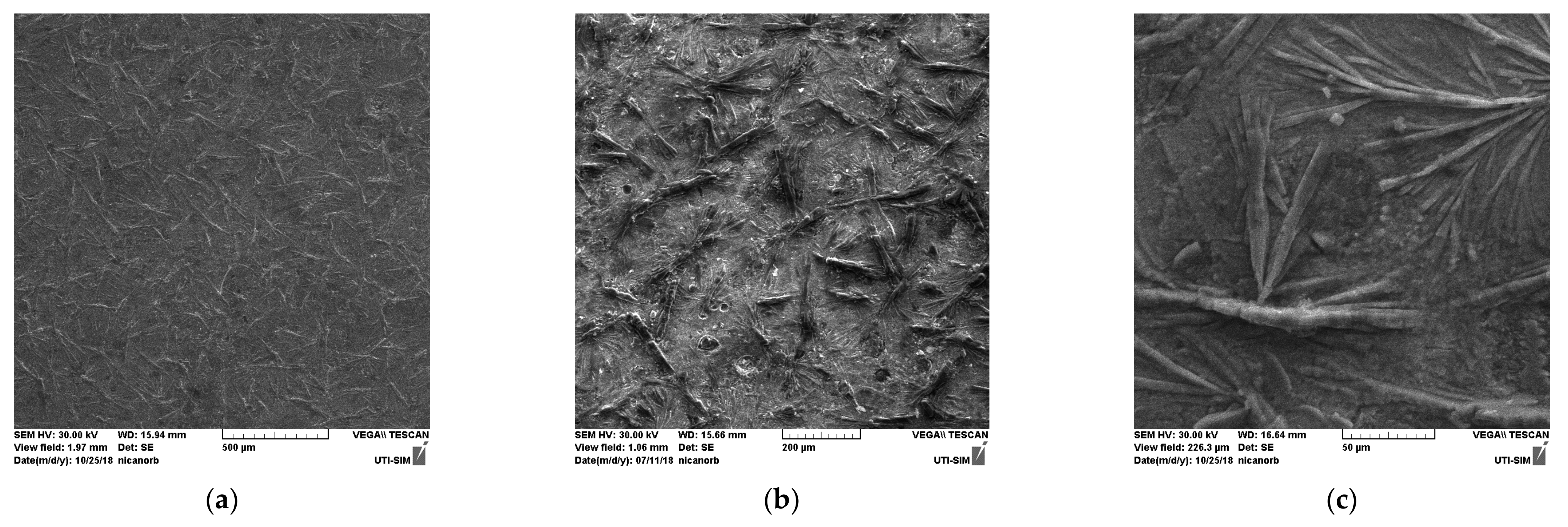
3.1. SEM and EDX Analysis of the Studied Samples

In Figure 2, the microstructure of cast iron with nodular graphite and the ferrite-pearlitic metal base is presented, where can be observed that the form of the graphite is nodular which indicates good resistance to both wet and dry wet and also good resistance to dynamic micro-shocks that can occur during the transport of sand, mud and abrasive particles.
After the phosphating process of nodular cast iron, the SEM micrographs (Figure 3) show the formation of a uniform layer consisting of Zn phosphate crystals which are interconnected.
The visual analysis of the SEM microphotographs allows highlights the fact that the surface of the sample is covered with acicular dendritic crystallites, uniformly distributed over the entire surface, with small gaps probably covered with ferric compounds.
In Figure 4, the cross sections of the deposited layers, the distribution of the elements on the surface and the thickness of the layers are presented.
The crystallites, in which phosphorus and zinc predominate along with oxygen, are crystals of zinc phosphate. Iron compounds predominate outside the dendrites. Additionally, it can be observed that the zinc phosphate layer is deposited on the graphite nodules. The thickness of the phosphate layer is between 10.55 and 4.5 µm in the vicinity of the graphite nodules (Figure 4a).

3.2. The Determination of the Contact Angle

The determination of the contact angle values aims to indicate if the character of the materials surface is hydrophilic or hydrophobic. In this case, this study is important for the characterization of the area of the liquid environment that causes corrosion and erosion in the submersible pump.
When a metallic material combines with a liquid, where hygroscopic phenomena occur, it tends to form a protective barrier layer of the liquid that physically adheres to the surface of the metal. The protective barrier layer is relatively stable against the static or turbulent motion of the surrounding fluid mass and exhibits a certain resilience that can dislodge airborne particles moving with the fluid, reducing the possibility of wall erosion. Protection is also associated with reduced corrosion intensity in the barrier layer area, which leads to longer operation and longer retention of working dimensions of functional parameters.
To measure the metal-liquid contact angle, three types of wastewaters with different pH (neutral, acid and basic) were used.
The wastewater used in the measurements was filtered with filter paper in order not to create problems in the measuring device (goniometer), there is a danger of clogging the drop release hole. Since the presence of particles in suspension has relatively little effect on the hydrophilic or hydrophobic nature of metallic materials, this does not significantly affect the results [22].
The results of the contact angle measurements were entered in Table 2, depending on the liquid, where the average values and the maximum deviations are entered and calculated.
Studying the values from Table 2, it can be observed that five measurements were made for each coupling, wastewater—metal support, to see to what extent repeatability of the results appears. The data, presented in column 7, represent the average of the values of the contact angle between the used water and the metal surface of coated and uncoated cast iron measured with the Kruss goniometer.
More research has been conducted because the accuracy of the contact surface is also involved, which, even if it has been ground and polished, can catch suspensions from the air that can influence the measurements.
The contact angle has values between 36° (phosphate nodular cast iron with neutral water) and 100.3° (nodular cast iron with neutral water).
Relatively close values between 94.9° and 100.3° of the surface tension of liquids on nodular cast iron indicate the impossibility of forming a protective film in almost all cases and the simultaneous occurrence of erosion and dynamic corrosion.
Studying the data shown in Table 2, it can be seen that the contact angle between all types of wastewaters and coated cast iron indicates a strong hydrophilic character, which favours the formation of protective barrier layers on the coated cast iron surface. Compared to uncoated cast iron, the values of the coating angles measured for the coated cast iron are uneven and vary a lot between 35° and 68°, due to both the porosity of the phosphate layer and its high roughness.
The high roughness and porosity of the deposited layer create favourable conditions for anchoring and stabilizing the liquid barrier layer that forms even if the liquid inside the pump moves at a high speed.
Photographs of the droplets (selection) are given in Figure 5 and Figure 6.

3.2.1. On the Nodular Cast Iron Solid Surface

The contact angle for the water drops on a cast iron support is greater than 90° in all situations, varying between 93.7° (in the case of water with pH—11) and 100.3° (in water with neutral pH), (values averages).
In these conditions the surface is hydrophobic, not allowing the formation of the protective layer.

3.2.2. On the Nodular Cast Iron Solid Surface Coated with a Zinc Phosphate Layer

Since the rotor is subject to multiple dynamic (mechanical erosion) and static (chemical corrosion) attacks, a thermochemical phosphating treatment was carried out on its surface, which influences both the corrosion behaviour and the character of the contact angle.
Due to the roughness and porosity of the surface layer, the character of the surface has changed, becoming hydrophilic, something that was also observed by Org W.E. et al. [23].
The contact angle for phosphate cast iron is between 44.9° in water with basic PH and 48.4° in water with neutral Ph. This indicates that distilled and wastewater adheres to the surface, which has a hydrophilic character, protective laminar layers forming on the surface. This protective layer limits the erosion of the rotor walls in dynamic mode, erosion due to the presence of suspended particles, metal microparticles, mud or sand. The protective effect of the lamellar layer is useful, especially at high rotor speed. Due to the type of deposition, which is porous, the contact angle has a non-uniform value, but it reflects the hydrophilic character of the surface.

3.3. Analysis of Tribological Properties of the Studied Samples

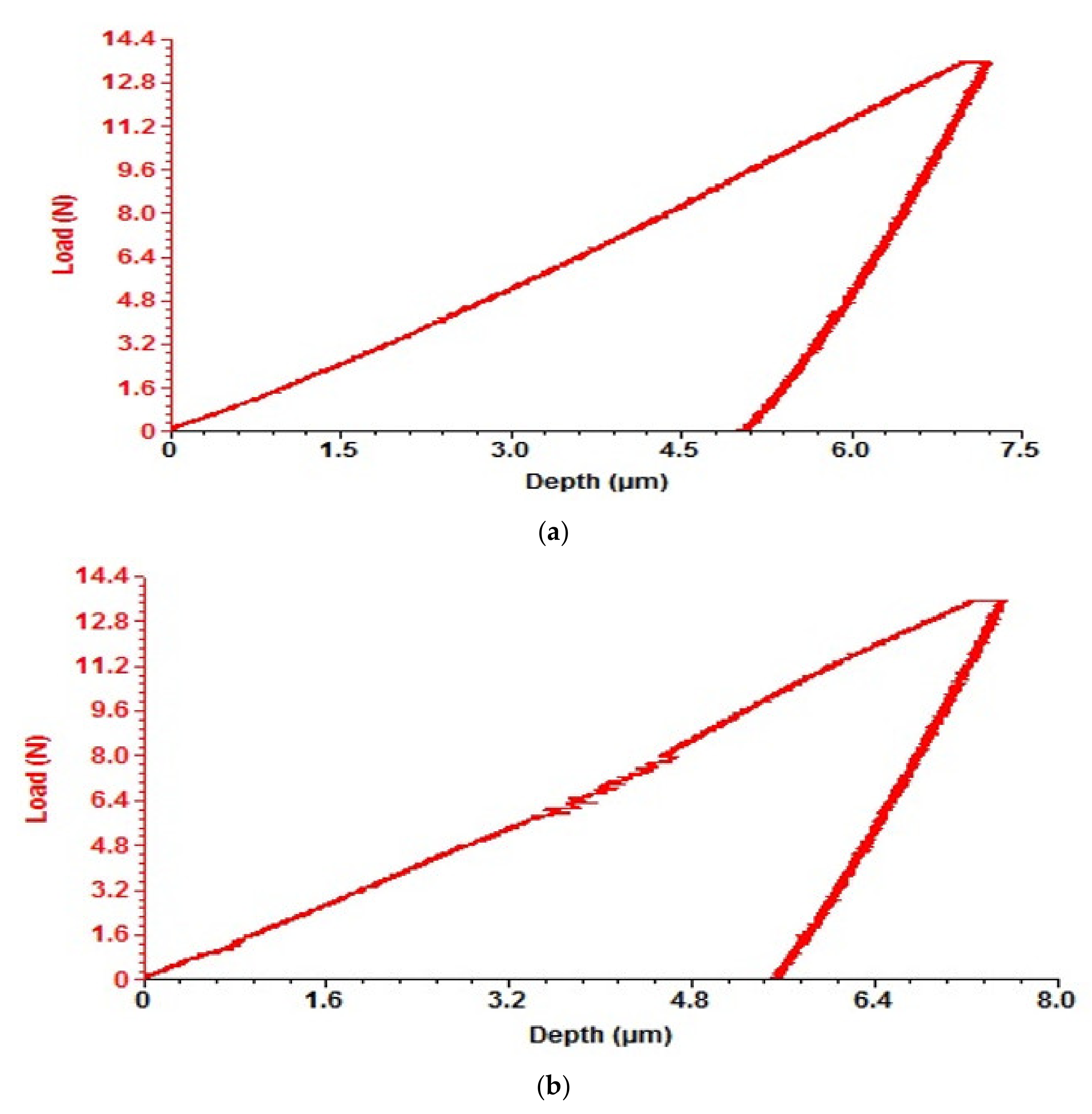
3.3.1. Scratch Test Analysis of Nodular Cast Iron and Coated Nodular Cast Iron

The used device records the variation in the normal load force, Fz (N), the variation in the friction force, Ff (N), the response force Fx (N) and the variation in the coefficient of friction (COF). The travel speed of the penetrator is 10 mm/min, and the system records the responses in real-time, t (s).
The normal loading force varies linearly and in the analysed case it reached the maximum value of 10 N in about 60 s.
The variations of the Fx and Ff forces show the response of the material (its reaction) to the action of the normal load force Fz on the surface which increases uniformly in value up to the recorded maximum area.
Due to the presence in the material structure of graphite nodules that have a fibrous lamellar structure, slight variations of the friction coefficient can be observed in the diagram, which shows relatively small values and very slightly increasing with the force Fx, from 0.15 to 0.24.
This is observed up to a force Fz value of 7 N. From 7 N to 10 N the normal force on the surface creates a weak at the beginning but at the end very strong hardening of the material in the action channel of the penetrator.
In Figure 7, the trace left by the penetrator on the non-phosphate nodular cast iron sample can be observed.
The hardening and agglomeration of the material have the effect of increasing the COF exponentially up to 0.64, which is achieved after 8 mm.
The growth takes place unevenly due to the appearance of areas of subsidence and pulling out of the material, especially in the mechanically weaker areas adjacent to the edges of the graphite nodules.
Along with the increase in the coefficent of friction, the friction force and the reaction force of the material also increase, having a variation graph similar to that of the COF.
Figure 8 shows the scratch test for non-phosphate ductile iron.
Crushes in the layer and material agglomerations exist both due to the presence of structural inhomogeneities of the basic metal matrix and to the presence of graphite nodules of spheroidal shapes but grouped in various ways and different sizes, a fact also recorded by Writzl Rovani et al. [2].
The mark obtained by the scratch test performed on the base material (substrate) was analysed with SEM and EDX.
In Figure 7, Figure 8 and Figure 9, the photo of the scratch and the SEM scratch test images covering the entire pressing area is presented, as well as the diagram of the pressing and reaction forces on the contact area.
The area is compact with no surface cracks, but with material pulls and adhesions occurring in the final area of the test.
Figure 10 shows the EDX analysis of the nodular cast iron studied, annealed after the scratch test, the effect of pressing the feeler both on the carbon nodules that act positively as a lubricant and on the metallic elements can be easily visualized. From the EDX analysis, Figure 10, the cruising of the ferrite-pearlitic base matrix with the partial crushing of the graphite nodules is observed. Portions of the carbon blades crushed during the test are observed to have been entrained and partially embedded in the area affected by the scratch.
In Figure 11, we have presented in detail the exit area of the feeler when the pressing force is maximum, but it does not create tearing of material or cracks in the pressing channel.
In Figure 12, 3D images, the relief of the scratch can be observed on the ferrite-pearlitic background of the sample.
In Figure 13 the scratch on the phosphate nodular cast iron sample is shown.
From the diagram in Figure 14, it can be seen that the phosphate cast iron has a higher scratch resistance than the non-phosphate one and presents a friction coefficient that does not vary with the increase in the pressing force, but has fluctuations due to the roughness of the surface specific to the presence of fibrous areas on the phosphate surface.
Phosphate cast iron has better scratch resistance than non-phosphate cast iron.
It is observed that the hardened area of the material does not appear when pressed, the variation in the response force Fx being linear and not exponential as in the non-phosphate sample.
The same type of variation has the friction force Ff which has a maximum of 3.6 N at a pressure Fz of 10 N.
For the non-phosphate sample, the pressing force has a value twice as high.
The phosphate nodular cast iron has a surface with irregularities, similar to an inflorescence, due to the deposition reactions of the phosphate compounds, which increases the roughness value of the layer and changes the physico-chemical properties of the outer layer.
The SEM analysis of the test scratch shows an area characteristic of an outer layer with high plasticity, with no visible cracks on the area of action of the penetrator.
It is observed that the pressed layer has the relief of the phosphate ribs flattened and deepened in the pressure channel made following the test. There is no tearing of material and no cracks or micro tapping, neither on the edge of the channel, nor at the base of the channel of action of the penetrator; this is due to the fact that the deposition is not rigid, similar to crusts, but has good elastoplastic properties, having values close to the values of the base material, and the lack of material tearing shows that the deposited layer has good adhesion to the substrate.
It is observed that the deposition takes place mainly in the area of the ferrite-pearlitic matrix of the nodular cast iron and does not take place in the area of the graphite nodules whose cleavage properties favour the sliding of the penetrator, something that also acts in the case of dynamic shocks encountered during the operation of the pump rotor submersible.
The pressure channel areas are shown in Figure 15.
In Figure 16, a 3D image representing a segment is presented, being the channel made following the test with the visualization of an area with graphite nodules.
The EDX analysis, in Figure 17, highlights the presence of phosphorus and zinc deposited due to the phosphating technology.
The graphite nodules are more visible in the channel made following the test, which shows that the phosphating is carried out mainly on the ferrite-pearlitic matrix and with weak adhesion on the carbon nodules. The phosphate layer is partially removed and partially embedded in the elastoplastically deformed linear zone of the penetrator.
The deposited layer has physical-mechanical properties close to those of the base material, which is highlighted by the shape of the channel from the scratch test.
The phosphate layer has good adhesion on the substrate of the ferrite-pearlitic matrix and weak adhesion on the graphite nodules.
The scratch test showed that the deposited layer has good plasticity properties, not being hard and brittle.

3.3.2. Analysis of the Microindentation Test

Microindentation was performed using a 30 µm radius ball indenter. Several sets of indentations were made, of which five values were kept that represent the most eloquent measurements. If the values differ greatly, the measurement is not considered valid.
This happens when the penetrator ball hits an area with graphite nodules, then the trace would be larger (graphite having low hardness compared to the base material) and the values of Young’s modulus and microhardness would not give indications that correspond to reality.
If the penetrator hits a zone of hard intermetallic compounds or a microzone of cementite, the indentation mark values would be much lower than they should be for the material.
The device records both the loading curve, which represents the variation in material deformation, measured in micrometres (µm), with the increase in the pressing force measured in Newton (N) and the unloading curve of the system.
On the microindentation load-discharge curve, sometimes there are areas with jumps or sudden variations such as a fracture along the stroke. These sudden jumps are areas when the motion sensor registers cracking of the surface layer during loading and material adhesion phenomena on the penetrator during unloading.
The plastic deformation of the layer is characterized by the distance between the starting and turning points on OX.
Five indentations were made both on the nodular cast iron sample and on the phosphate nodular cast iron sample to observe by comparison the properties of hardness and homogeneity of the deposition.
In all indentations, the maximum loading force was 13.534 N.
In the area of the base material (cast iron with nodular graphite not deposited), the residual deformation has values between 7.65 µm and 4.84 µm; the system behaving similar to elasto-plastic, with the different values characterizing areas with different components (areas with ferrite-pearlitic matrix and areas with graphitic nodules with weaker elastic characteristics).
No jumps are observed in the loading diagram, except in test 2 when a micro-indentation was made on an area with graphite nodules.
In the case of the other four tests made on the ferrite-pearlitic base matrix, no jumps appear, which indicates the absence of cracks. During unloading, small irregularities are observed on the curve, which indicates the appearance of slight adhesions on the penetrator, shown in Figure 18.
In the case of the microindentations made on the phosphate sample, a higher variation in the residual deformation is observed, which is composed between 4.68 µm and 10.85 µm, which is due to the non-uniformity characteristics of the phosphate layer, which does not have hardness characteristics superior to the base layer, Figure 19.
No deviations due to cracking appear on the loading curve except for test 2, which also varies in shape compared to the other curves because the substrate area on which the indentation was made was on a graphite nodule, but the jumps appear on the unloading curves in almost all tests, which implies the presence of adhesions.
From the point of view of the resistance against deformation by the base material, it is observed that it varies between 7.18 N/µm and 7.85 N/µm, being relatively uniform.
An increase in non-uniformity is observed for the phosphate material, the variation being between 5.22 N/µm and 6.51 N/µm. This indicates a slightly lower stiffness of the surface, so the deposited layer is more elastic than the substrate, which is beneficial for the part’s behaviour in dynamic micro-stresses due to suspended particles or edges.
Some observations can be made:
-
the behaviour of the layer during elastoplastic deformation is similar in the analysed positions;
-
the structural non-uniformity of the layer causes cracking processes during mechanical loading and adhesion processes during mechanical unloading;
-
if the elastic behaviour of the layer is analyzed, it is superior to that presented by the substrate.
The analysis system also provides other useful information in the case of sizing a tribological system. Thus, the contact depth gives indications about the microhardness of the support material and the deposited layer, in the first case it varies around the value of 5.60 μm, corresponding to the microhardness of 1.95 GPa, and in the second case, it varies around the value of 6.55 μm, corresponding to microhardness of 1.67 Gpa. It can be considered that the average depth of elastoplastic penetration of the micro-indenter in the treated layer is 10%–15% higher than the superficial layer of the non-deposited part.
In the case of the Contact Area parameter, it represents the response of the deposition material to the applied force and is all the better the larger the surface. In this case, the layer adheres well to the substrate and the interface is good. The contact surface is large, varying between 13,269.934 μm2 and 5822.497 μm2, with average values of 6500–7000 μm2.

4. Conclusions

The obtained results allowed us to highlight important aspects, presented as follows:
  • The deposition of the phosphate layer on the cast iron surface changes the hydrophobic behaviour into a hydrophilic behaviour. Therefore, this behaviour leads to the formation of a boundary layer during pump functioning which will protect the material against corrosion and erosion;
  • The scratch tests highlighted that the deposited phosphate layer has physical-mechanical properties close to those of the base material. Additionally, the tests revealed that the zinc phosphate layer has good plasticity properties;
  • The phosphate layer has good adhesion on the substrate of the ferrite-pearlitic matrix and weak adhesion on the graphite nodules;
  • Microindentation tests shows that cast-iron and coated cast iron have almost similar microhardnesses;
  • Brittle areas, both on the coated and uncoated sample, appear when the penetrator is pressed on graphite nodules, an area with high fragility;
  • In the area of the ferrite-pearlitic matrix, microzones appear with adhesions to both the phosphate and non-phosphate samples, which demonstrates the close plasticity of the two materials.

Author Contributions

Conceptualization, writing and investigation C.N.; writing an original draft, project administration and scientific supervision, M.A.; methodology, investigation, data curation and validation, M.C.P.; data curation, validation and writing—reviewing and editing, D.-P.B.-N.; resources, investigation and formal analysis C.B. All authors have read and agreed to the published version of the manuscript.

Funding

This work was supported by Gheorghe Asachi Technical University of Iaşi—TUIASI- Romania, Scientific Research Funds, FCSU-2022.

Institutional Review Board Statement

Not applicable.

Informed Consent Statement

Not applicable.

Data Availability Statement

Not applicable.

Acknowledgments

This work was supported by a research grant of the TUIASI, project number PN-III-27PFE/2021, COMPETE 2.0, financed by the Romanian Government, and in accordance with the proposals of the Representative of the Government of Romania.

Conflicts of Interest

The authors declare no conflict of interest.

References

  1. Nejneru, C.; Burduhos-Nergis, D.-P.; Axinte, M.; Perju, M.C.; Bejinariu, C. Corrosion Behaviour of Nodular Cast Iron Used for Rotor Manufacturing in Different Wastewaters. Coatings 2022, 12, 911. [Google Scholar] [CrossRef]
  2. Writzl, V.; Rovani, A.C.; Pintaude, G.; Lima, M.S.F.; Guesser, W.L.; Borges, P.C. Scratch Resistances of Compacted Graphite Iron with Plasma Nitriding, Laser Hardening, and Duplex Surface Treatments. Tribol. Int. 2020, 143, 106081. [Google Scholar] [CrossRef]
  3. Teixeira, C.H.S.B.; Alvarenga, E.A.; Vasconcelos, W.L.; Lins, V.F.C. Effect of Porosity of Phosphate Coating on Corrosion Resistance of Galvanized and Phosphated Steels Part I: Measurement of Porosity of Phosphate. Mater. Corros. 2011, 62, 771–777. [Google Scholar] [CrossRef]
  4. Baloyi, T.; Maledi, N.; Andrews, A. Corrosion Performance of Zinc Phosphate Coatings Deposited on AA6061-HDG Steel. Mater. Chem. Phys. 2022, 283, 126009. [Google Scholar] [CrossRef]
  5. Galvan-Reyes, C.; Fuentes-Aceituno, J.C.; Salinas-Rodríguez, A. The Role of Alkalizing Agent on the Manganese Phosphating of a High Strength Steel Part 2: The Combined Effect of NaOH and the Amino Group (NH4OH, Mono-Ethanolamine and NH4NO3) on the Degradation Stage of the Phosphating Mechanism. Surf. Coat. Technol. 2016, 299, 113–122. [Google Scholar] [CrossRef]
  6. Burduhos-Nergis, D.P.; Cazac, A.M.; Corabieru, A.; Matcovschi, E.; Bejinariu, C. Characterization of Zinc and Manganese Phosphate Layers Deposited on the Carbon Steel Surface. In IOP Conference Series: Materials Science and Engineering; Institute of Physics Publishing: Bristol, UK, 2020; Volume 877, p. 012012. [Google Scholar]
  7. Azhaarudeen, S.; Faruck, A.A.M.; Nevosad, A. Tribological Behaviour and Wear Mechanisms of Manganese Phosphate Coatings under Dry Reciprocating Sliding Contact Conditions. Tribol. Int. 2018, 122, 189–199. [Google Scholar] [CrossRef]
  8. de Mello, J.D.B.; Costa, H.L.; Binder, R. Friction and Wear Behaviour of Steam-Oxidized Sintered Iron Components Coated with Manganese Phosphate. Wear 2007, 263, 842–848. [Google Scholar] [CrossRef]
  9. Baltatu, M.S.; Vizureanu, P.; Sandu, A.V.; Munteanu, C.; Istrate, B. Microstructural Analysis and Tribological Behavior of Ti-Based Alloys with a Ceramic Layer Using the Thermal Spray Method. Coatings 2020, 10, 1216. [Google Scholar] [CrossRef]
  10. Tkaya, M.B.; Mezlini, S.; Mansori, M.E.; Zahouani, H. On Some Tribological Effects of Graphite Nodules in Wear Mechanism of SG Cast Iron: Finite Element and Experimental Analysis. Wear 2009, 267, 535–539. [Google Scholar] [CrossRef]
  11. Xia, D.H.; Deng, C.M.; Macdonald, D.; Jamali, S.; Mills, D.; Luo, J.L.; Strebl, M.G.; Amiri, M.; Jin, W.; Song, S.; et al. Electrochemical Measurements Used for Assessment of Corrosion and Protection of Metallic Materials in the Field: A Critical Review. J. Mater. Sci. Technol. 2022, 112, 151–183. [Google Scholar] [CrossRef]
  12. Cai, X.; Xu, Y.; Zhao, N.; Zhong, L.; Zhao, Z.; Wang, J. Investigation of the Adhesion Strength and Deformation Behaviour of in Situ Fabricated NbC Coatings by Scratch Testing. Surf. Coat. Technol. 2016, 299, 135–142. [Google Scholar] [CrossRef]
  13. Behera, S.K.; Kumar, P.A.; Dogra, N.; Nosonovsky, M.; Rohatgi, P. Effect of Microstructure on Contact Angle and Corrosion of Ductile Iron: Iron-Graphite Composite. Langmuir 2019, 35, 16120–16129. [Google Scholar] [CrossRef] [PubMed]
  14. Jeong, J.J.; Jeong, B.Y.; Kim, M.H.; Lee, C. Characterization of TiN Coatings on the Plasma Nitrided Spheroidal Graphitic Cast Iron Substrates. Surf. Coat. Technol. 2002, 150, 24–30. [Google Scholar] [CrossRef]
  15. Mendas, M.; Benayoun, S. Comparative Study of Abrasion via Microindentation and Microscratch Tests of Reinforced and Unreinforced Lamellar Cast Iron. Friction 2019, 7, 457–465. [Google Scholar] [CrossRef]
  16. Xie, Y.; Hawthorne, H.M. A Model for Compressive Coating Stresses in the Scratch Adhesion Test. Surf. Coat. Technol. 2001, 141, 15–25. [Google Scholar] [CrossRef]
  17. Burduhos-Nergis, D.-P.; Vizureanu, P.; Sandu, A.V.; Bejinariu, C. Phosphate Surface Treatment for Improving the Corrosion Resistance of the C45 Carbon Steel Used in Carabiners Manufacturing. Materials 2020, 13, 3410. [Google Scholar] [CrossRef] [PubMed]
  18. Burduhos-Nergis, D.P.; Bejinariu, C.; Sandu, A.V. Phosphate Coatings Suitable for Personal Protective Equipment; Materials Research Forum LLC: Millersville, PA, USA, 2021; Volume 89, ISBN 9781644901113. [Google Scholar]
  19. Kerstner, E.K.; Kunst, S.R.; Beltrami, L.V.R.; Vega, M.R.O.; Scienza, L.C.; de Fraga Malfatti, C. Anticorrosive Performance of Commercial Nanoceramic Coatings on AISI 1010 Steel. Mater. Res. 2014, 17, 1497–1506. [Google Scholar] [CrossRef]
  20. Standard Practice for Surface Wettability of Coatings, Substrates and Pigments by Advancing Contact Angle Measurement. Available online: https://www.astm.org/d7334-08r22.html (accessed on 23 August 2022).
  21. Yildirim Erbil, H. The Debate on the Dependence of Apparent Contact Angles on Drop Contact Area or Three-Phase Contact Line: A Review. Surf. Sci. Rep. 2014, 69, 325–365. [Google Scholar] [CrossRef]
  22. Savin, C.; Nejneru, C.; Tugui, C.A.; Perju, M.C.; Sandu, A.V.; Bejinariu, C. Analysis of Contact Angle for Metallic Materials in Wastewater Pumps. Rev. Chim. 2019, 70, 2811–2817. [Google Scholar] [CrossRef]
  23. Org, W.E.; Chen, Y.; Wang, J.; Wen, S.; Zhang, J.; Yu, X.; Mao, Y. ELECTROCHEMICAL SCIENCE Synthesis of Rose-Like Sheet Zinc Phosphate by the Induction-Calcination Method and Its Application as a Corrosion Inhibitor in Coatings. Int. J. Electrochem. Sci. 2021, 16, 210456. [Google Scholar] [CrossRef]
Figure 1. Low-pressure single channel centrifugal pump: (a) rotor; (b) the corroded and worn area of the rotor.
Coatings 12 01384 g001
Figure 2. The microstructure of cast iron with nodular graphite and the ferrite-pearlitic metallic base: (a) 500×; (b) 200×; (c) 100×.
Coatings 12 01384 g002
Figure 3. SEM micrographs of the nodular cast iron coated with Zn phosphate layer (a) 100×; (b) 500×; (c) 1000×.
Coatings 12 01384 g003
Figure 4. Cross section through the phosphate layer (1000×): (a) section showing the thickness of the layer, (b) section showing the mapping of the elements, (c) section showing the deposition near the graphite nodules (1500×).
Coatings 12 01384 g004
Figure 5. The contact angle for the surface of the cast iron using wetting agents (a) DWW1 (contact angle: 99.1°); (b) DWW2 (contact angle: 97.2°); (c) DWW3 (contact angle: 93.7°).
Coatings 12 01384 g005
Figure 6. The contact angle for surface of the coated cast iron: (a) DWW1 (contact angle: 48.3°); (b) DWW2 (contact angle: 44.9°); (c) DWW3 (contact angle: 48.4°).
Coatings 12 01384 g006
Figure 7. Photograph of the non-phosphate nodular cast iron specimen after the scratch test.
Coatings 12 01384 g007
Figure 8. Photograph of the non-phosphate nodular cast iron specimen after the scratch test.
Coatings 12 01384 g008
Figure 9. Scratch test for uncoated nodular cast iron SEM images (ae).
Coatings 12 01384 g009
Figure 10. Scratch test for non-phosphate nodular cast iron images EDX analysis (a) SEM photo, (b) distribution of all elements, (c) distribution of Fe, (d) distribution of C, (e) distribution of Mn.
Coatings 12 01384 g010
Figure 11. Scratch test: (a) probe output; (b) detail.
Coatings 12 01384 g011
Figure 12. Scratch test—3D—probe exit area: (a) general view; (b) detail highlighting graphite nodules.
Coatings 12 01384 g012
Figure 13. Photograph of the phosphate nodular cast iron specimen after the scratch test.
Coatings 12 01384 g013
Figure 14. Scratch test for phosphate nodular cast iron.
Coatings 12 01384 g014
Figure 15. Scratch test for phosphate nodular cast iron sample at size scales of: (a) 500 µm; (b) 500 µm; (c) 200 µm; (d) 100 µm; (e) 50 µm; (f) 50 µm.
Coatings 12 01384 g015aCoatings 12 01384 g015b
Figure 16. A 3D photo representing a segment being the channel made after the test with the visualization of an area with graphite nodules.
Coatings 12 01384 g016
Figure 17. EDX images for the scratch test on the phosphate nodular cast iron sample: (a) general view; (b) Zn distribution; (c) Fe distribution; (d) distribution P; (e) all elements.
Coatings 12 01384 g017
Figure 18. Microindentation tests for non-phosphate nodular cast iron sample. (a) Test 1, (b) Test 2, (c) Test 3, (d) Test 4, (e) Test 5.
Coatings 12 01384 g018aCoatings 12 01384 g018b
Figure 19. Microindentation tests for phosphate nodular cast iron sample. (a) Test 1, (b) Test 2, (c) Test 3, (d) Test 4, (e) Test 5.
Coatings 12 01384 g019aCoatings 12 01384 g019b
Table 1. The chemical composition of cast iron which is used for dynamic constructive components of submersible pump manufacturing.
ElementCMnSiNiMgPSCrTiCuFe
Wt, %4.500.092.280.120.090.050.040.020.020.01balance
Table 2. The values of the contact angle for the studied samples in three different wastewaters.
Samples and SolutionsContact Angle Measurements (C.A.) [Degrees]Mean [Degrees]Deviation [Degrees]
Coated cast iron—DWW-13648.35149.241.345.18
Cast iron—DWW-1 99.4100.399.197.294.998.22.2
Coated cast iron -DWW-265.960.844.940.455.15312.3
Cast iron—DWW-2 95.398.795.897.298.397.11.5
Coated cast iron -DWW-368.160.961.148.438.154.411
Cast iron—DWW-3 95.193.596.792.193.794.21.7
Publisher’s Note: MDPI stays neutral with regard to jurisdictional claims in published maps and institutional affiliations.

