1. Introduction
Plasma nitriding is a widely used chemical heat treatment technology. This method uses the active nitrogen atoms generated during the cathode sputtering process at a relatively low temperature (350–570 °C) to accumulate on the surface of a workpiece, diffuse into the substrate, and finally form a nitriding-modified layer with excellent performance. For a variety of alloy materials, it can improve surface hardness, fatigue resistance, wear resistance, and corrosion resistance [
1,
2,
3,
4,
5,
6,
7]. At present, the methods most commonly used to increase the thickness of the nitride layer are to increase the nitriding temperature or to extend the process time [
8]. However, these methods have some disadvantages, such as the coarsening of the structure and reduced hardness [
9,
10]. Therefore, the question of how to increase the thickness of the modified layer in a short time presents a difficult challenge. Researchers have found that adding some catalysts can improve the efficiency of nitriding. Among them, rare earth (RE) elements have been proven to be effective catalysts for chemical heat treatment [
11].
In the early 1980s, researchers studied the chemical heat treatment of RE. In the following decades, scholars explored the effects of RE catalysis and microalloying [
12]. Many researchers observed that in the process of gas carburizing, gas carbonitriding, gas nitrocarburizing, and plasma nitriding, RE elements can diffuse deeper to the surface [
13,
14,
15]. At the same time, the involvement of RE elements causes the nitrogen to diffuse deeper into the nitrided layer. Yan et al. [
16,
17] showed that rare earth elements induced nitriding and observed similar catalytic effects; they also studied the general catalytic effect of rare earth elements on the nitriding process of various steels, including stainless steel [
18,
19] and alloy steel [
20,
21,
22].
Due to its good wear resistance, high fatigue strength and high strength, 38CrMoAl steel is widely used in many industries [
23,
24]. However, in some applications, it cannot meet the requirements of high surface hardness and corrosion resistance. Therefore, surface modification approaches are used to improve the structure and properties of 38CrMoAl steel. However, there are few studies on the surface modification of 38CrMoAl steel, especially with the addition of RE. Therefore, it is very important to study the effect of plasma nitriding following the addition of RE on the thickness, surface hardness, phase composition, and corrosion resistance of a modified 38CrMoAl steel layer.
2. Materials and Methods
The test material was 38CrMoAl steel with a thickness of 5 mm and a diameter of ϕ 20 mm, and its chemical compositions are shown in
Table 1. The steel was solution-treated in an SXL-1400C box-type electric furnace and austenitized at 940 °C for 1 h, after which oil quenching treatment was performed. A QG-1 metallographic cutting machine was used to cut the solution-treated sample into 5 mm thin slices. The surface was polished with 120# water sandpaper. Next, absolute ethanol was used for ultrasonic cleaning for 10–15 min. The sample was then blow dried with a hair dryer before being wiped with a dust-free cloth, weighed, and tied together with a thin iron wire. The 1 × 1 × 1 cm
3 rare earth (RE) lanthanum was cut into 1/8 cube blocks, and the RE was hung on the cathode platform with the iron wire, in order to maximize the sputtering of RE.
Before plasma nitriding in the LDMC-30AFZ ion nitriding furnace, the furnace was evacuated to below 10 pa. The nitriding atmosphere was NH3 (100 mL/min) at 550 °C for 4, 8, and 12 h. A CPA-225D electronic balance (Sai Dolis scientific instruments Beijing co., Ltd., Beijing, China) was used to measure the mass before and after the nitriding sample. After nitriding, the surface of the sample was polished with 120#-2000# water sandpaper. The polished sample was corroded with 4% nitric acid alcohol solution for 15 s, rinsed with alcohol, and dried. The cross-section structure and thickness of the modified layer was observed with a 9XB-PC metallographic microscope, the surface morphology was observed with a ThermoScientific™Apreo C (TEM, JEOL Ltd, Tokyo, Japan) model field emission scanning electron microscope, and a HV-1000IS microhardness tester (Shanghai Jvjing Precision Instrument Manufacturing Co., Ltd., Shanghai, China) was used to test the hardness of the modified layer. The phase composition of the sample surface after nitrogen treatment was characterized by a D8 Advance X-ray diffractometer (Bruker, Karlsruhe, Germany). Anodic polarization tests were employed to estimate the corrosion resistance of the specimens in a 3.5 wt.% NaCl solution. The reference electrode was Ag/AgCl and a platinum column was used as the auxiliary electrode. A corrosion resistance test was performed in a CHI604E B16276 electrochemical workstation.
3. Results and Discussion
3.1. Microstructure and Phase Composition of Modified Layer
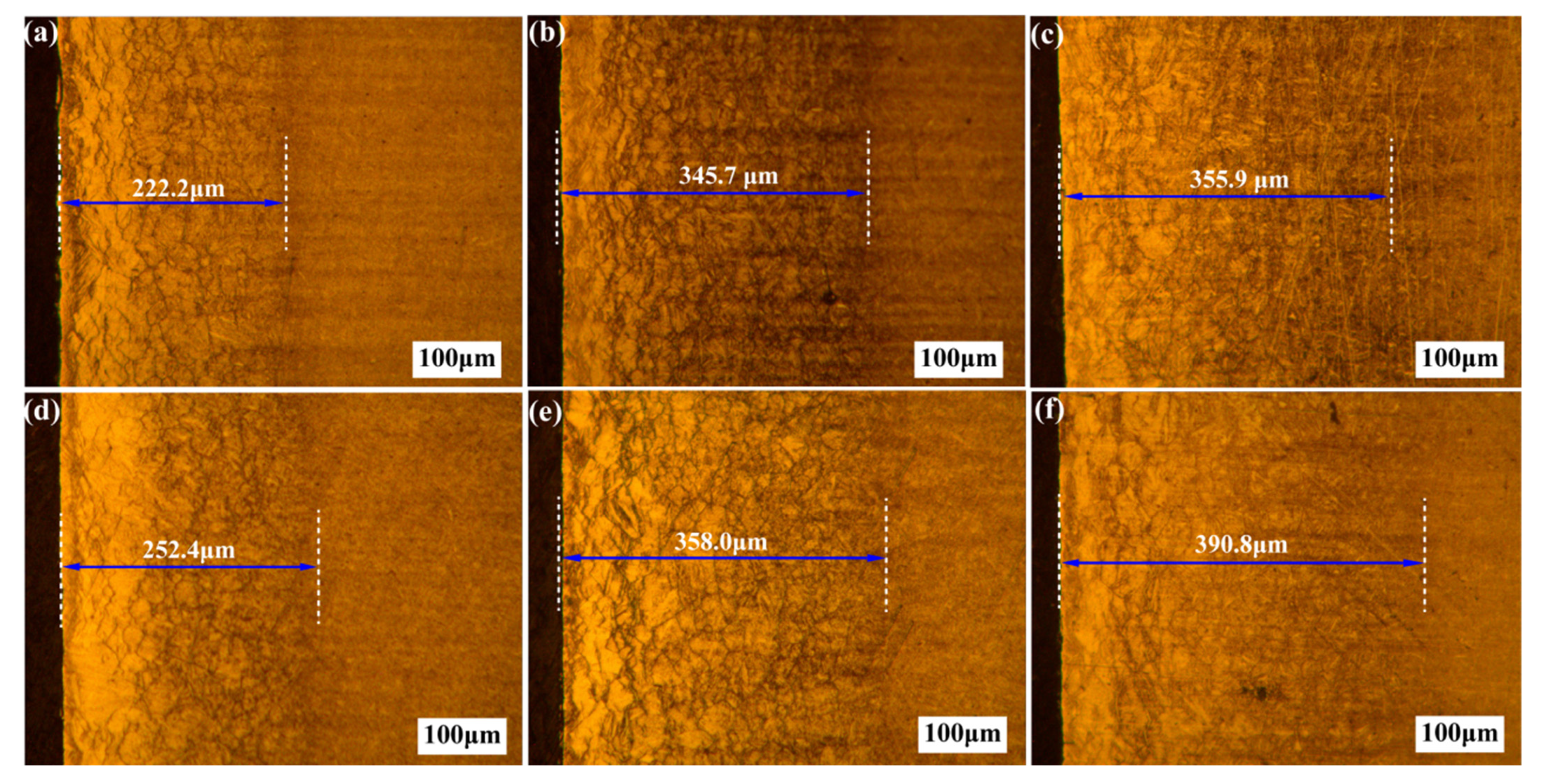
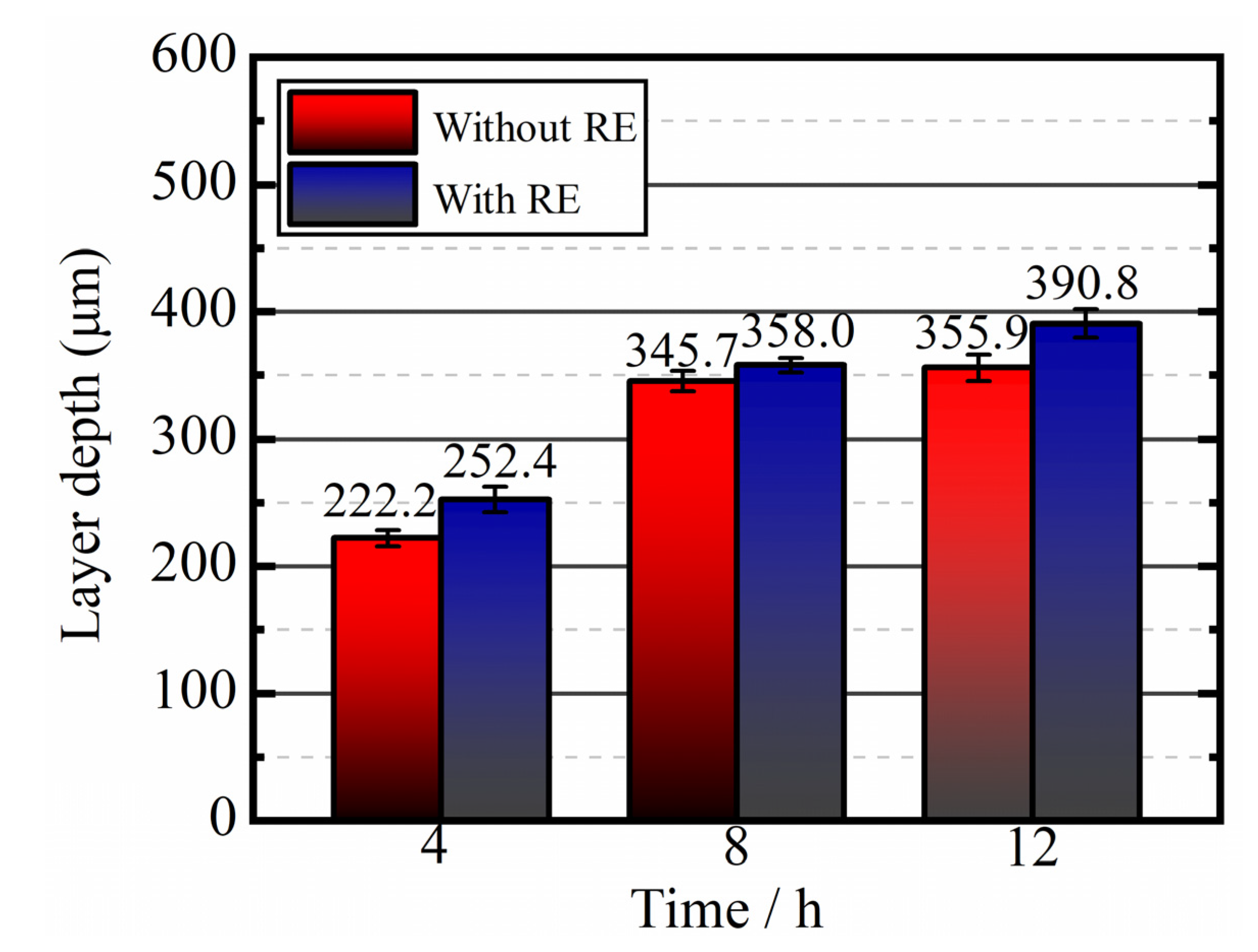
Figure 1 shows the metallographic microstructure of the modified layer of 38CrMoAl steel without rare earth (RE) and with rare earth. The nitrided layer without RE was clearly divided from the matrix, and the microstructure of the nitrided layer was uniform. After nitriding for 4, 8, and 12 h, the thickness of the modified layer was 222.2, 345.7, and 355.9 μm, respectively; the thickness of the modified layer increased gradually with the extension of nitride time. However, at the same temperature of 550 °C, after the addition of RE, the nitrided layer thickened with time to 252.4, 358.0, and 391.8 μm (4, 8, 12 h), respectively., The thickened histograms of the nitrided modified layer with RE and without RE after nitriding for 4, 8, and 12 h are shown in
Figure 2. The modified layer was thickened by 30.2, 12.3, and 34.9 μm at 4, 8, and 12 h, respectively. Compared with the nitriding layer without the addition of RE, the thickening rates of the RE nitriding layer were 13.6%, 3.50% and 9.80%, respectively, indicating that it was easier to obtain a thicker nitriding layer with the addition of RE at the same nitriding time intervals. The addition of RE in nitrided steel increased the concentration of microscopic crystal defects, such as vacancies and dislocations, in the modified layer and caused lattice distortion of the iron atoms around it, which was beneficial for the adsorption and diffusion of the nitrogen atoms. Therefore, in a short period of time, a higher nitrogen concentration was formed in the matrix, providing a very high nitrogen potential and concentration gradient for the inward diffusion of nitrogen atoms, which also provided good thermodynamic conditions for the diffusion of nitrogen atoms.
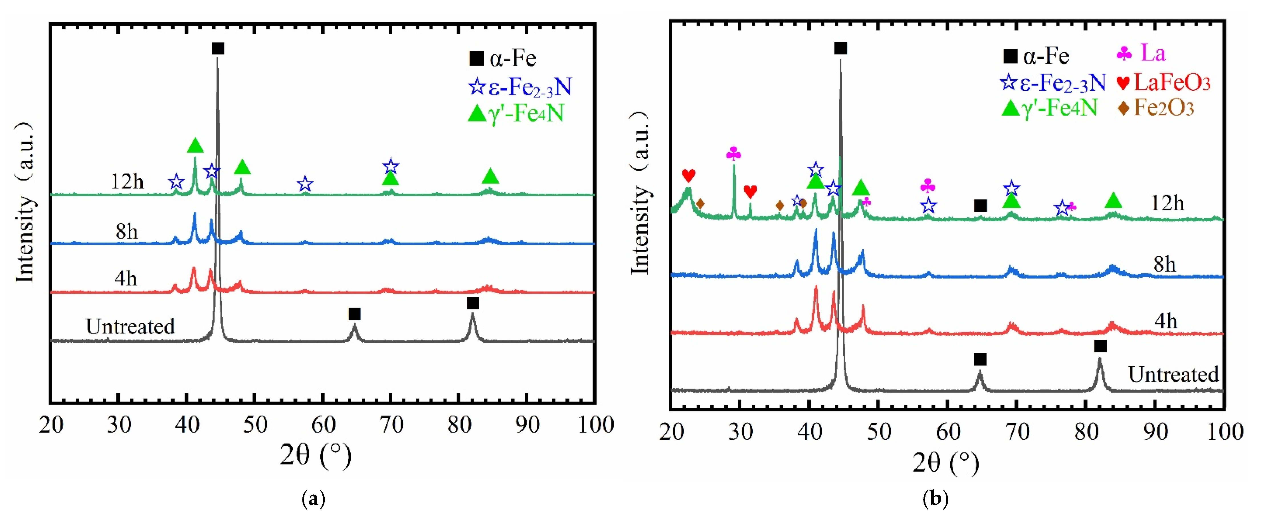
As shown in the XRD patterns of
Figure 1a–c, which correspond to
Figure 3a without RE nitridating, the main phase of the modified layer without RE nitridation was γ’-Fe
4N and the secondary phase was ε-Fe
2-3N. However, La and LaFeO
3 oxides were detected in the XRD patterns shown in
Figure 1d–f, corresponding to
Figure 3b with the addition of RE nitridation for 12 h. Because LaFeO
3 showed a strong adsorption effect on N atoms [
25], the thickening rate of the modified layer increased with the addition of RE nitriding within the same timeframe.
3.2. Weight Gain and Microhardness of Modified Layer
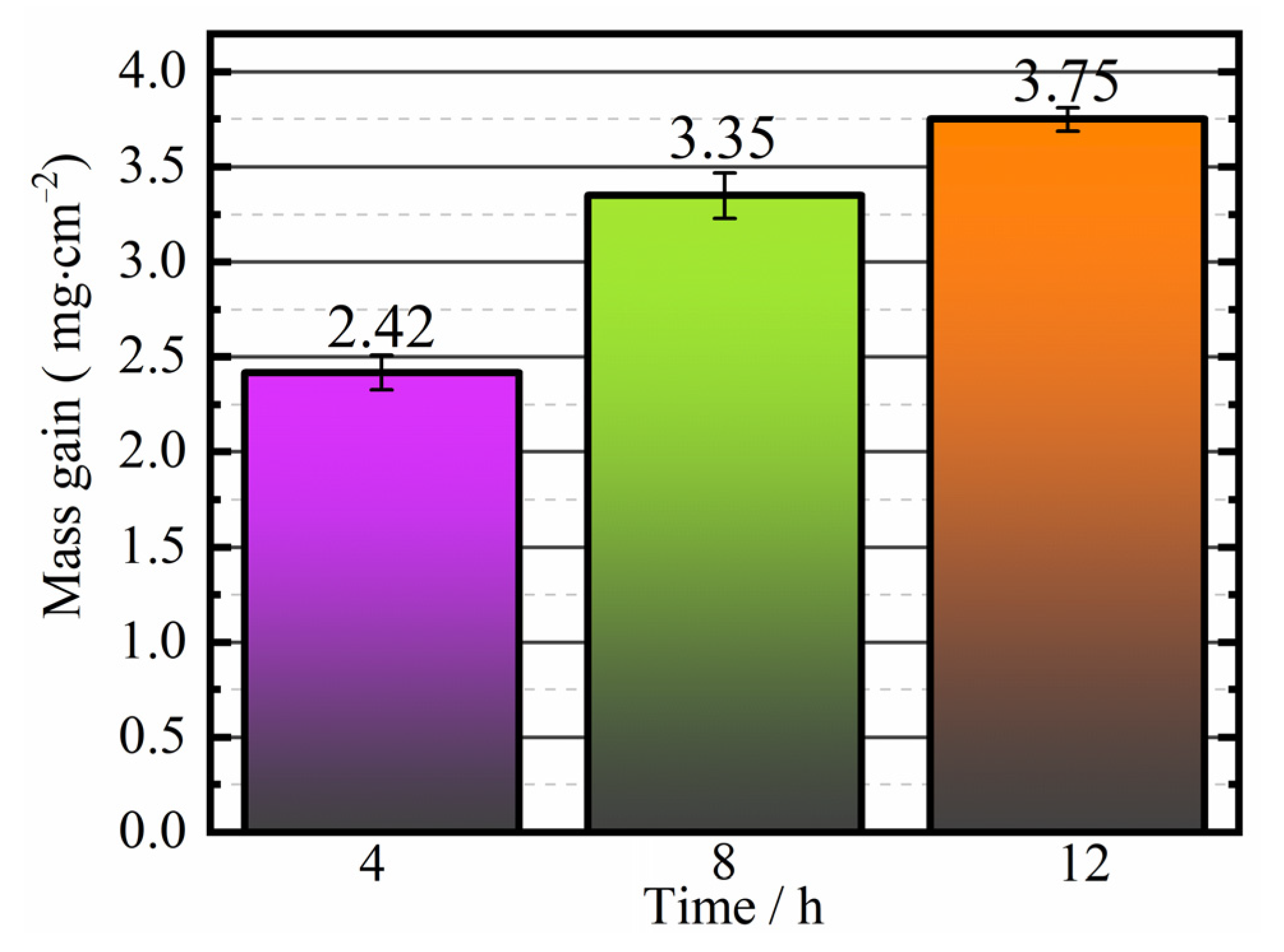
Figure 4 shows the histogram (4, 8, and 12 h) of the thickening of the steel without the RE-nitridated layer. The weight gain was 2.42, 3.35 and 3.75 mg/cm
2 at each respective time interval.
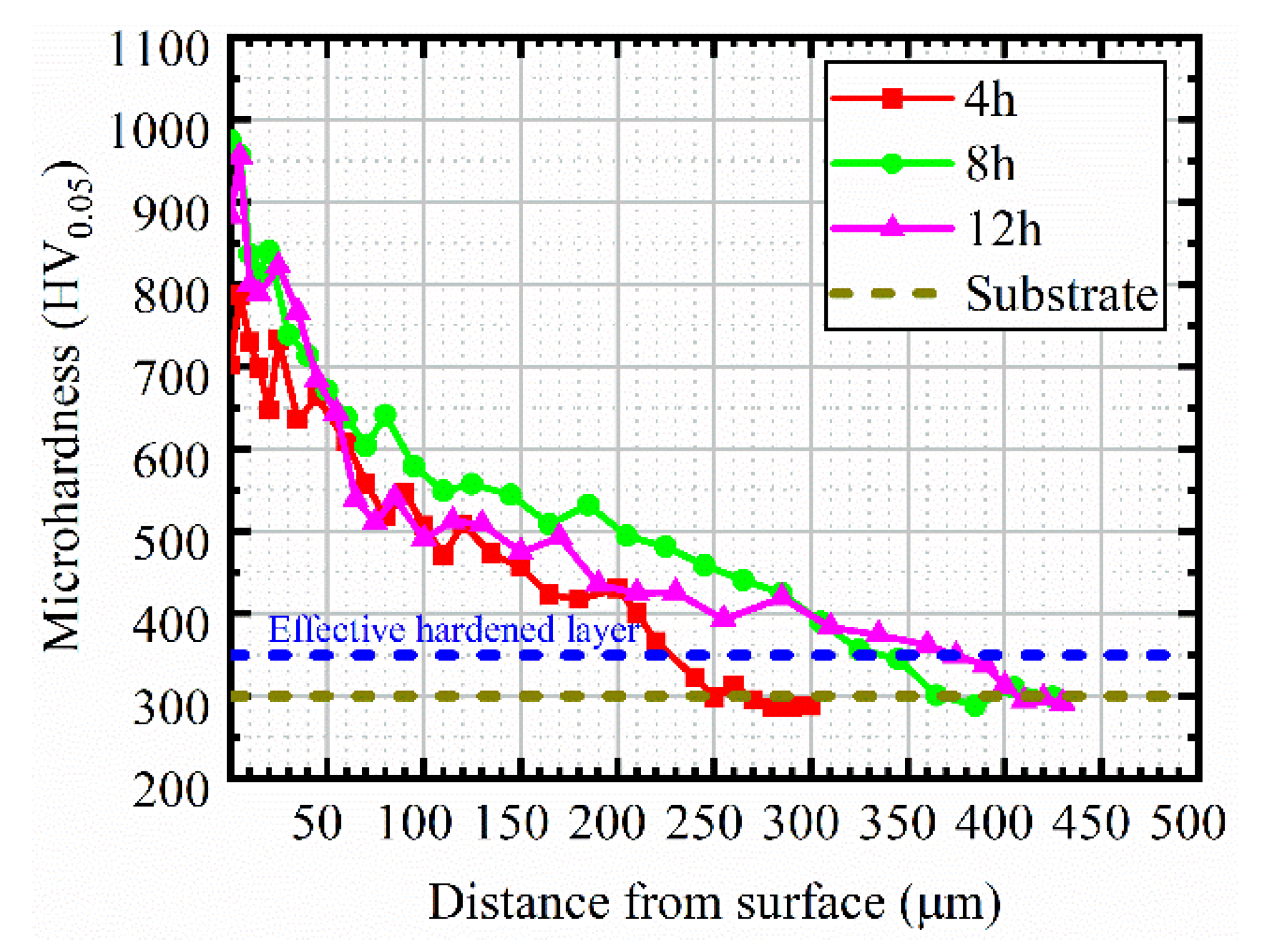
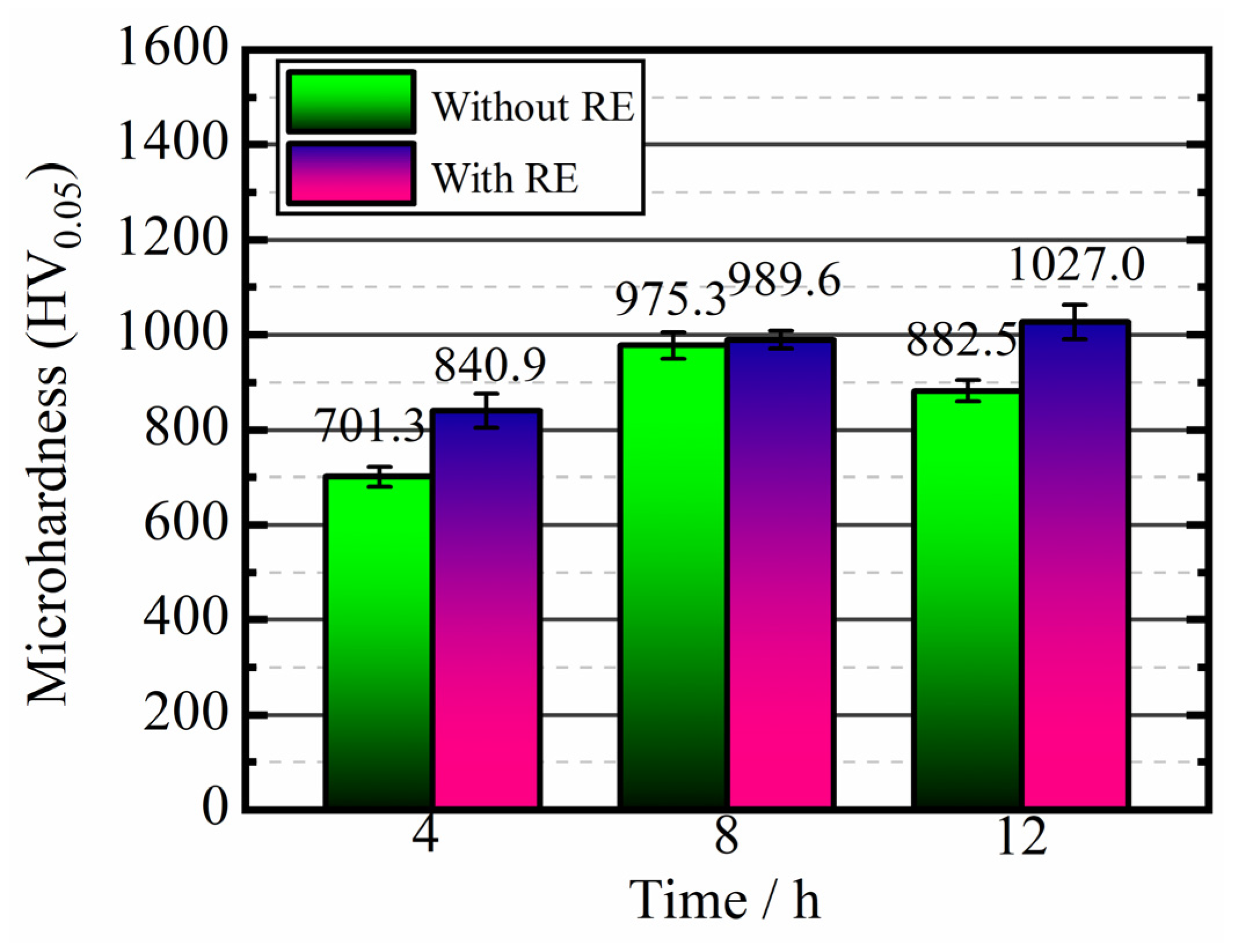
Figure 5 shows the microhardness diagram of the modified layer. After 4 h of nitriding, the surface hardness was 701.3 HV
0.05. After nitriding for 8 h, the surface hardness was 975.3 HV
0.05. After 12 h of nitriding, the surface hardness of the modified layer was 882.5 HV
0.05.
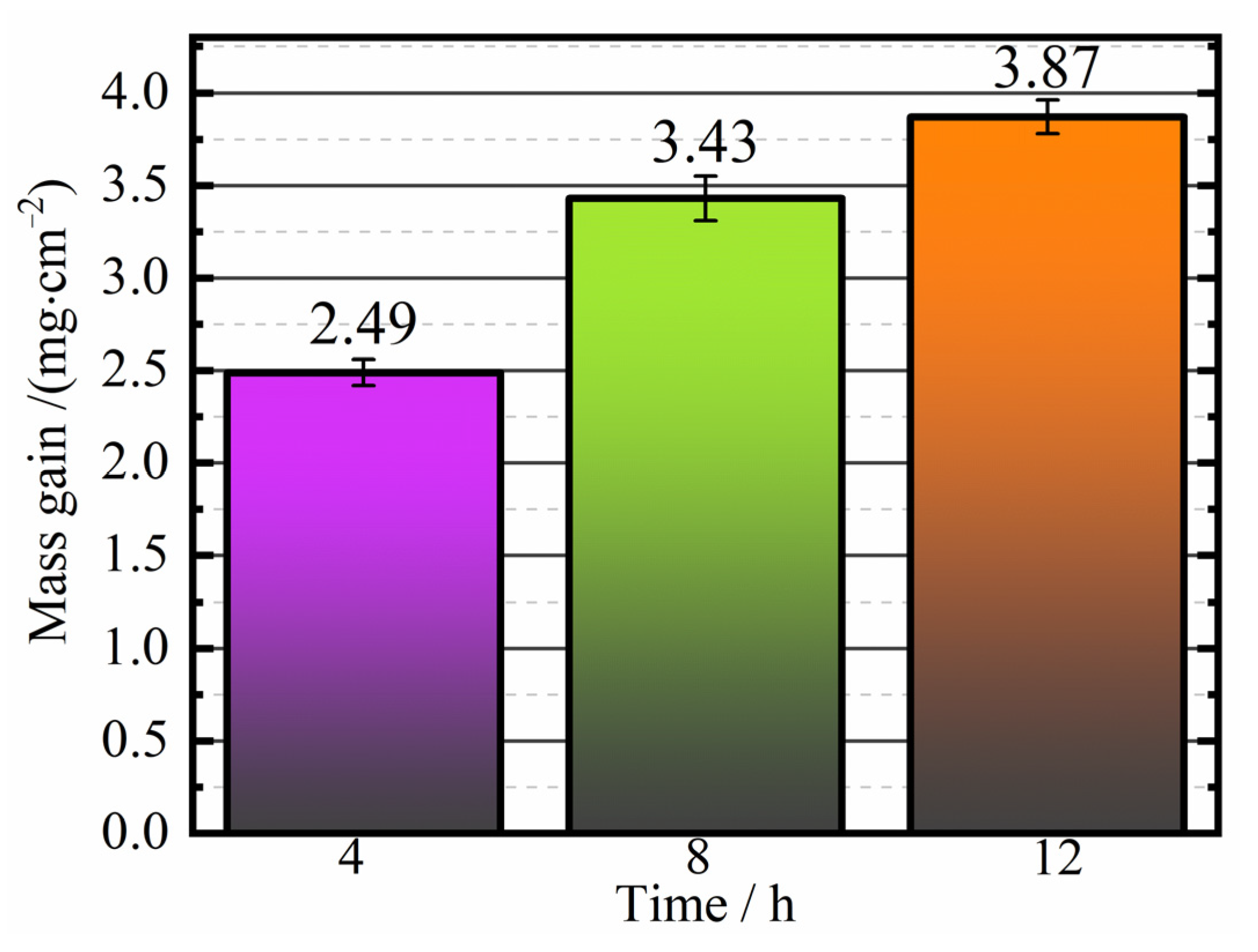
Figure 6 shows the histogram of the weight gain after nitriding with the addition of for 4, 8, and 12 h. The weight gain was 2.49, 3.43, and 3.87 mg/cm
2, respectively.
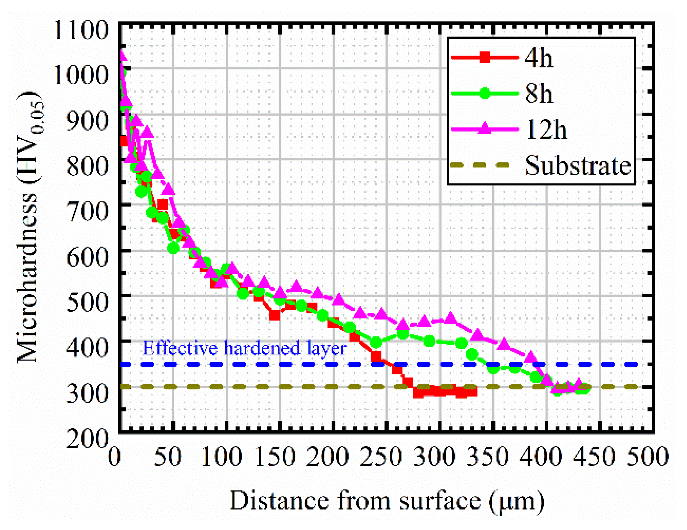
Figure 7 shows the microhardness distribution under nitriding conditions with RE. After nitriding for 4, 8, and 12 h, the surface hardness was 840.9, 989.6, and 1027.0 HV
0.05, respectively, and the surface hardness reached its peak at 12 h. According to the microhardness bar chart of the nitriding surface without and with rare earth in
Figure 8, the increase percentage of the surface hardness after nitriding with RE over time was 19.7%, 1.47%, and 16.3%, for each respective time interval. Therefore, the surface hardness improved after the addition of RE nitriding. This was mainly because the addition of RE refines the microstructure of the nitrided layer and adjusts the phase proportion [
26]. Moreover, there are dispersion strengthening and solid solution strengthening effects after adding rare earth nitriding. At the same time, the infiltration of rare earth elements leads to serious lattice distortion and increases dislocation around the boundary, resulting in grain boundary strengthening.
3.3. Element Distribution in Modified Layer and EDS Energy Spectrum Analysis
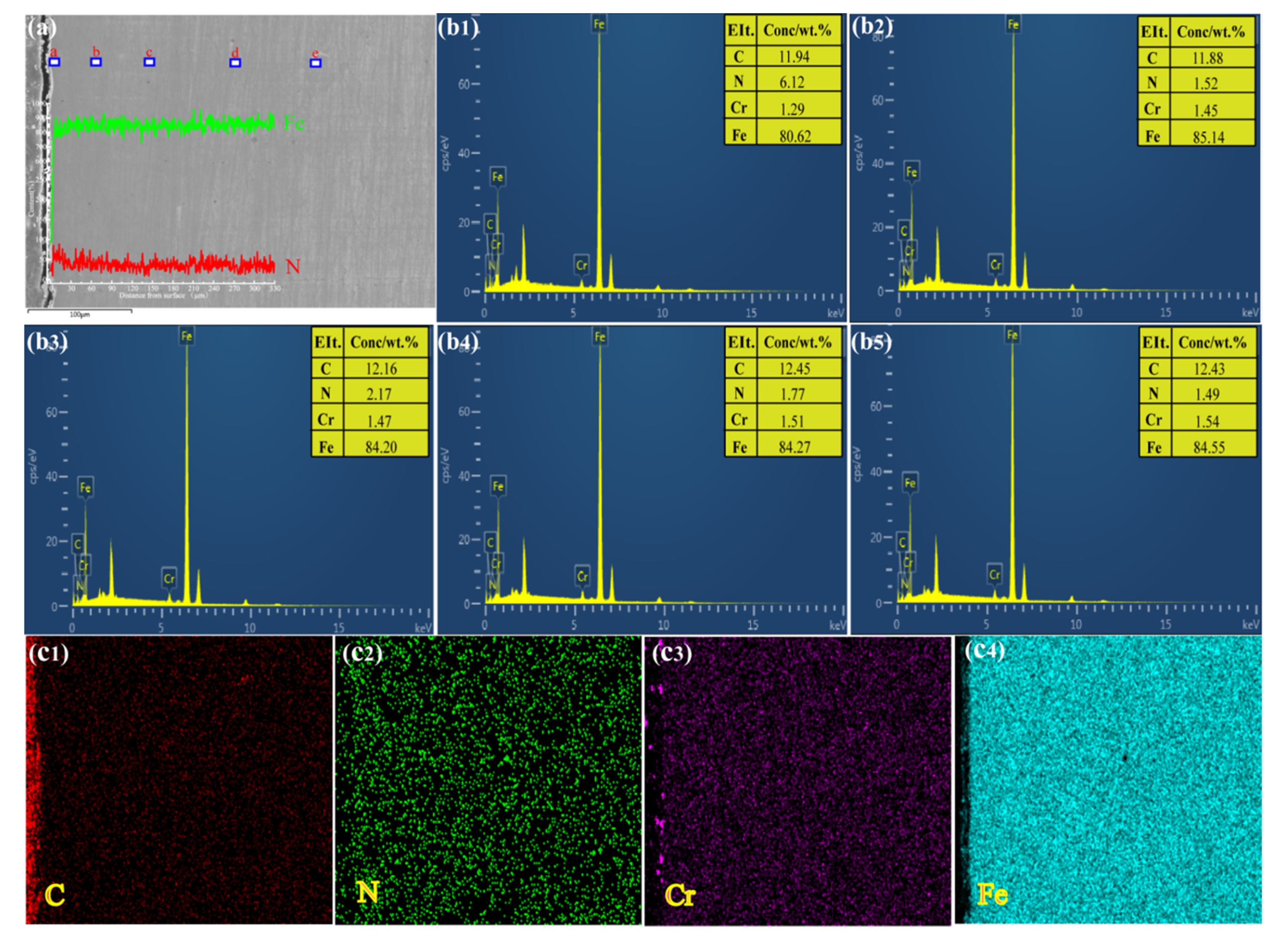
The modified surface layers of the 12 h samples without RE nitriding were magnified by 100. Point scanning and plane scanning were performed for a, b, c, d, and e in
Figure 9a by an EDS analyzer.
Figure 9b1–b5 and
Figure 9c1–c4 show the modified layer EDS spectrum test results. The distance from the surface of the modified layer was gradually transferred to the matrix, and the content distribution of each element was uneven. In combination with the line scan and plane scan in
Figure 9a,b1–b5, it is also shown that under nitriding conditions without RE, the content of the element N in the modified layer didnot change significantly, and the distribution of the elements C, Fe, and Cr in the modified layer was relatively uniform.
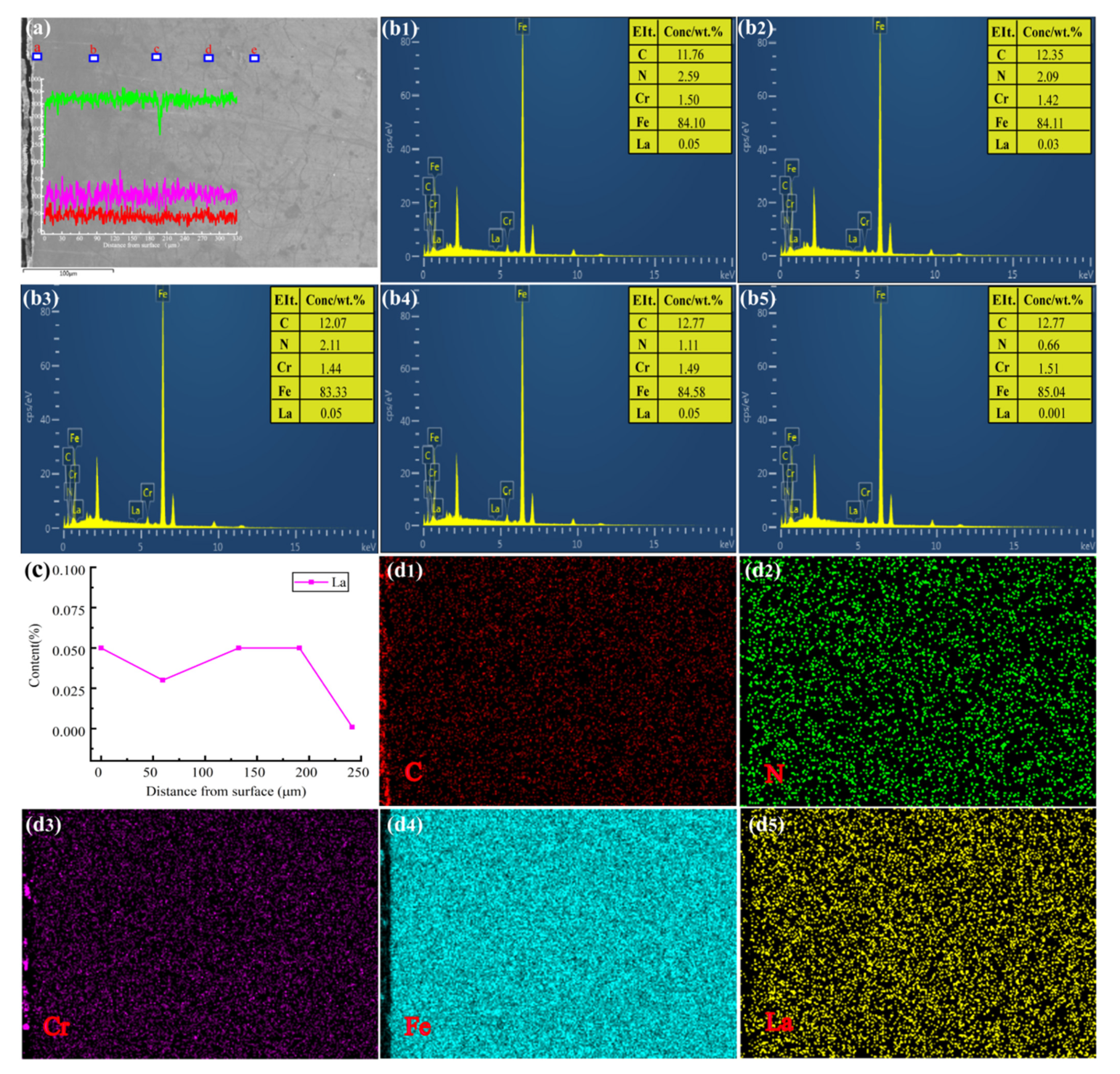
Figure 10 shows the surface morphology and elements content after 12 h of RE nitriding. As can be seen from
Figure 10b1–b5, the La content in the modified layer was small, while the N content showed a downward trend. At position c in
Figure 10a, dot analysis was performed at 130.60 μm of the permeable layer, and the content of La was consistent with the surface content of the nitrided layer, indicating that RE atoms can be diffused into the modified layer. This was confirmed by mid-plane scanning, shown in
Figure 10d5, but with the thickening of the nitrided layer, the modified layer contained a trace of La. Comparison between
Figure 9b1 and
Figure 10b1 shows that the content of N element on the surface without RE nitriding was higher than it was after RE nitriding, although the thickness of the modified layer on the surface without RE nitriding was thinner than that of the layer subjected to nitriding with RE [
27]. This indicates that the increase of the nitrogen concentration or nitrogen the potential did not necessarily lead to the thickening of the modified layer. The thickness of the modified layer is not only related to the external N potential, but also to the internal diffusion of N atoms [
28].
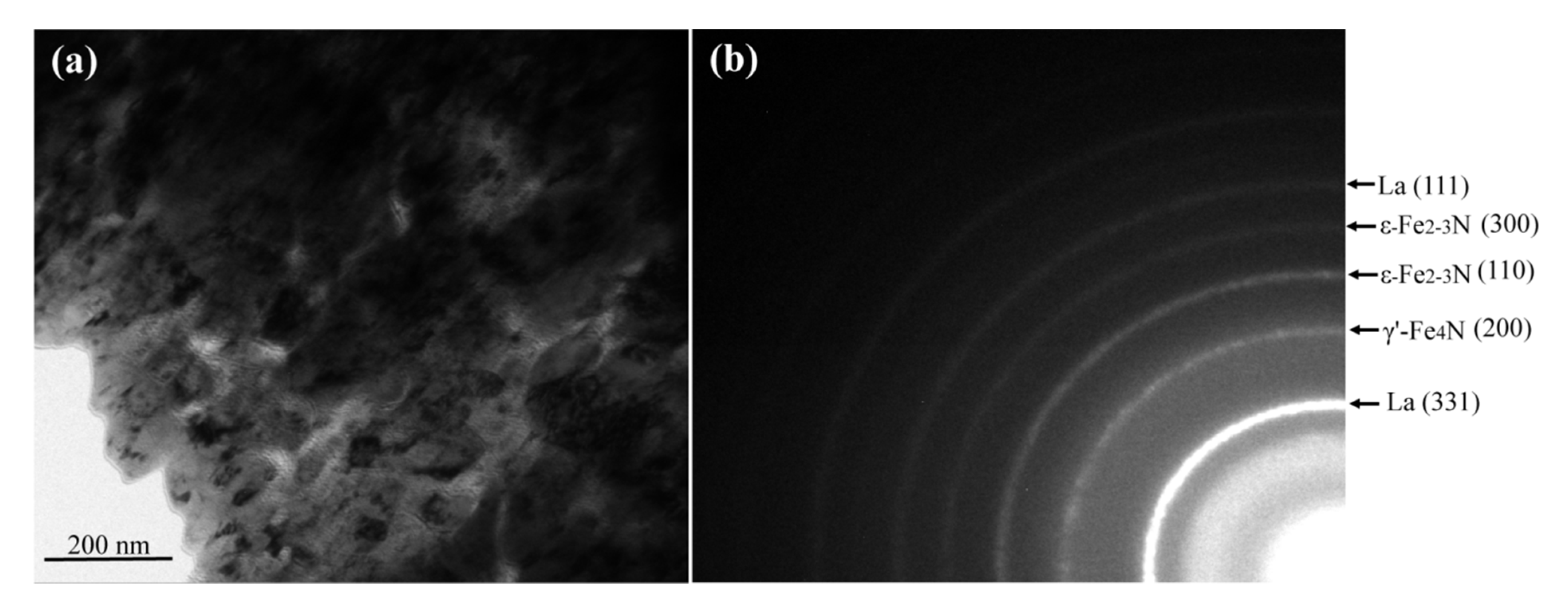
The surface structure of the 12 h RE-nitrided samples was further studied by transmission electron microscopy (TEM). The bright-field image and the corresponding selected region electron diffraction (SAED) map are shown in
Figure 11. A large number of nanocrystals were observed, as shown in
Figure 11a. The size of the precipitated phase was extremely small, with the maximum size no greater than 60 nm. The results showed that the addition of RE refined the grain size and produced a microalloying effect on the modified layer.
Figure 12b shows a clear diffraction ring caused by a large number of nanocrystals, indicating that these La, γ’-Fe
4N, ε-Fe
2-3N, and La phases existed in the outermost layer in the form of nanocrystals. The size of these phases was generally limited to 100 nm, so they can be referred to as nanophases. Yan et al. [
29,
30] obtained similar results with plasma nitriding, and found that the existence of the nano-phase helps to improve the hardness and wear resistance of the nitriding layer. Furthermore, these phases are consistent with the XRD results in
Figure 3b.
3.4. Polarization Curve and Fitting Data
The polarization curve data in
Figure 12a were used for fitting, and the results are shown in
Table 2. After nitriding for 4, 8, and 12 h, the corrosion rates of the modified layer were 21.405 × 10
−2 mm/a, 21.939 × 10
−2 mm/a, and 25.714 × 10
−2 mm/a, respectively. The corrosion rates peaked after 12 h of nitriding. The current corrosion density was also increased to 2.186 × 10
−5 A/cm
2 compared with that of the non-nitrided sample. After fitting the polarization curve data shown in
Figure 12b, we obtained the fitting results shown in
Table 3. After nitriding with RE for 4, 8, and 12 h, the corrosion rates of the modified layer were 16.092 × 10
−2 mm/a, 20.754 × 10
−2 mm/a, and 15.089 × 10
−2 mm/a, respectively; the corrosion rate decreased, increased and then decreased again. The corrosion rates of the RE-nitrided samples reached their minimum at 12 h, and the current density of the RE-nitrided samples decreased to 1.282 × 10
−5 A/cm
2 compared with the samples without RE, and the width of passivation zone was wider. Tang [
25] discussed the main reasons for the enhanced corrosion resistance of ε-nitride compounds on the workpiece surface. The X-ray diffraction analysis in
Figure 3b shows that the presence of La and oxide LaFeO
3 significantly improved the intensity of the ε-Fe
2−3N diffraction peak and increased the content of the ε-phase in the samples. Because ε-nitrides are the most important parameters controlling the corrosion resistance of nitrided samples, the corrosion resistance of our rare earth-nitrided samples was enhanced at 12 h.
3.5. Thermodynamics of the Modified Layer
Because the nitrided atmosphere was NH
3, the main reaction in the furnace was:
The decomposition of ammonia produced [N] atoms (Equation (1)), some of which penetrated into the surface of the workpiece, and the other part formed N2, which became a stable gas.
The nitride produced by the decomposition of iron nitride provided the conditions for the formation of rare earth nitride [
31].
The RE formed compounds with nitrogen (N), a gap element of chemical heat treatment, and the bond changed from metal to ionic. Rare earths also reacted with hydrogen (H) to form rare earth hydrides.
Since the hydrogenation of rare earth can occur above 300 °C:
Trace RE hydrides floating in the furnace flow improved the adsorption capacity of the workpiece surface diffusion. When RE hydrides are attracted to the workpiece surface, the following rare earth nitriding reactions occur:
The thermodynamic driving force of the decomposition of ε-Fe
2N (Reaction 2) was greater than that of γ′-Fe
4N (Reaction 3). Therefore, it is speculated that γ′-Fe4N was still in the modified layer [
32]. The calculated negative ΔG1
T 0 shows that the reaction occurs spontaneously from left to right in the range of 575–700 °C, forming active compounds of rare earth and nitrogen.
4. Conclusions
We studied the effect of the addition of rare earth (RE) to a modified layer of 38CrMoAl steel by plasma nitriding at 550 °C for 4, 8, and 12 h, and in an HN3 atmosphere. The following conclusions were drawn:
(1) For nitriding without the addition of RE for 4, 8, and 12 h, the thickness of the modified layers was 222.2, 345.7, 355.9 μm for each respective timeframe, the weight gains were 2.42, 3.35, and 3.75 mg/cm2, respectively, and the maximum surface hardness was 882.5 HV0.05, at 12 h. After nitriding with the addition of RE for 4, 8, and 12 h, the modified layers were thickened by 30.2, 12.3 and 34.9 μm, respectively, and the weights were 2.49, 3.43 and 3.87 mg/cm2, respectively. The maximum surface hardness was 1027.0 HV0.05, at 12 h.
(2) After 12 h of nitriding with RE, La, LaFeO3, and trace Fe2O3 appeared in the modified layer. The diffraction peak of γ’-Fe4N in the RE nitriding layer was weakened compared with the layer nitrided without RE, while the diffraction peak of ε-Fe2-3N was enhanced. Meanwhile, La, γ’-Fe4N, ε-Fe2-3N, and La phases existed in the outermost layer in the form of nanocrystals.
(3) After nitriding with the addition of RE for 12 h, the corrosion rate of the modified layer decreased to a minimum of 15.089 × 10⁻² mm/a, and the current density also decreased to a minimum of 1.282 × 10⁻⁵ A/cm2; consequently, the corrosion resistance increased.
Author Contributions
Conceptualization, D.L. and Y.Y.; methodology, D.L. and Y.Y.; software, L.H.; validation, T.H.; formal analysis, Y.Y.; investigation, D.L., R.L. and T.H.; resources, Y.Y. and M.Y.; data curation, Y.Y., T.H. and D.L.; writing—original draft preparation, Y.Y.; writing—review and editing, D.L., Y.Y. and H.C.; visualization, L.H.; supervision, M.Y.; project administration, Y.Y. and M.Y.; funding acquisition, Y.Y. and M.Y. All authors have read and agreed to the published version of the manuscript.
Funding
Supported by the National Natural Science Foundation of China (51401113) and Natural Science Foundation of Heilongjiang Province of China (E2016069), Heilongjiang Postdoctoral Financial Assistance (LBH-Z16061), The Fundamental Research Funds in Heilongjiang Provincial Universities (135309504).
Institutional Review Board Statement
Not applicable.
Informed Consent Statement
Not applicable.
Data Availability Statement
Data is contained within the article.
Conflicts of Interest
The authors declare no conflict of interest.
References
- Bell, T.; Sun, Y.; Liu, Z.R.; Yan, M.F. Rare earth surface engineering. Heat Treat. Met. 2000, 27, 12–13. [Google Scholar]
- Tuckart, W.; Forlerer, E.; Iurman, L. Delayed cracking in plasma nitriding of AISI 420 stainless steel. Surf. Coat. Technol. 2007, 202, 199–202. [Google Scholar] [CrossRef]
- Yan, H.; Zhao, L.; Chen, Z.; Hu, X.; Yan, Z. Investigation of the surface properties and wear properties of AISI H11 steel treated by auxiliary heating plasma nitriding. Coatings 2020, 10, 528. [Google Scholar] [CrossRef]
- Espitia, L.A.; Varela, L.; Pinedo, C.E.; Tschiptschin, A.P. Cavitation erosion resistance of low temperature plasma nitrided martensitic stainless steel. Wear 2013, 301, 449–456. [Google Scholar] [CrossRef]
- Yang, J.; Liu, Y.; Ye, Z.; Yang, D.; He, S.; Li, X. Grease-lubricated tribological behaviour of nitrided layer on 2Cr13 steel in vacuum. Appl. Surf. Sci. 2010, 256, 4072–4080. [Google Scholar] [CrossRef]
- Olzon-Dionysio, M.; Campos, M.; Kapp, M.; de Souza, S.; de Souza, S.D. Influences of plasma nitriding edge effect on properties of 316L stainless steel. Surf. Coat. Technol. 2010, 204, 3623–3628. [Google Scholar] [CrossRef]
- Ahangarani, S.; Mahboubi, F.; Sabour, A.R. Effects of various nitriding parameters on active screen plasma nitriding behavior of a low-alloy steel. Vacuum 2006, 80, 1032–1037. [Google Scholar] [CrossRef]
- Aghajani, H.; Torshizi, M.; Soltanieh, M. A new model for growth mechanism of nitride layers in plasma nitriding of AISI H11 hot work tool steel. Vacuum 2017, 141, 97–102. [Google Scholar] [CrossRef]
- Karakan, M.; Alsaran, A.; Çelik, A. Effect of process time on structural and tribolo-gical properties of ferritic plasma nitrocarburized AISI 4140 steel. Mater. Des. 2004, 25, 349–353. [Google Scholar] [CrossRef]
- Fattah, M.; Mahboubi, F. Comparison of ferritic and austenitic plasma nitriding and nitrocarburizing behavior of AISI 4140 low alloy steel. Mater. Des. 2010, 31, 3915–3921. [Google Scholar] [CrossRef]
- Medina, A.; Aguilar, C.; Béjar, L.; Oseguera, J.; Ruíz, A.; Huape, E. Effects of post-discharge nitriding on the structural and corrosion properties of 4140 alloyed steel. Surf. Coat. Technol. 2019, 366, 248–254. [Google Scholar] [CrossRef]
- Yuan, Z.X.; Yu, Z.S.; Tan, P.; Song, S.H. Effect of rare earths on the carburization of steel, Mater. Sci. Eng. A 1999, 267, 162–166. [Google Scholar] [CrossRef]
- Yan, M.F. Study on absorption and transport of carbon in steel during gas carburizing with rare-earth addition. Mater. Chem. Phys. 2001, 70, 242–244. [Google Scholar] [CrossRef]
- Yan, M.F.; Pan, W.; Bell, T.; Liu, Z. The effect of rare earth catalyst on carburizing kinetics in a sealed quench furnace with endothermic atmosphere. Appl. Surf. Sci. 2001, 173, 91–94. [Google Scholar] [CrossRef]
- Chen, X.; Bao, X.; Xiao, Y.; Zhang, C.; Tang, L.; Yao, L.; Cui, G.; Yang, Y. Low-temperature gas nitriding of AISI 4140 steel accelerated by LaFeO3 perovskite oxide. Appl. Surf. Sci. 2019, 466, 989–999. [Google Scholar] [CrossRef]
- Liu, R.L.; Yan, M.F. Effects of rare earths on nanocrystalline for nitrocarburised layer of stainless steel. Mater. Struct. 2017, 33, 1346–1351. [Google Scholar] [CrossRef]
- Yan, M.F.; Liu, R.L. Influence of process time on microstructure and properties of17-4PH steel plasma nitrocarburized with rare earths addition at low temperature. Appl. Surf. Sci. 2010, 256, 6065–6071. [Google Scholar] [CrossRef]
- Yan, M.F.; Liu, R.L. Martensitic stainless steel modified by plasma nitrocarburizing at conventional temperature with and without rare earths addition. Surf. Coat. Technol. 2010, 205, 345–349. [Google Scholar] [CrossRef]
- Wang, X.; Yan, M.; Liu, R.; Zhang, Y. Effect of rare earth addition on microstructure and corrosion behavior of plasma nitrocarburized M50NiL steel. J. Rare Earths 2016, 34, 1148–1155. [Google Scholar] [CrossRef]
- Wu, Y.; Yan, M. Effects of lanthanum and cerium on low temperature plasma ni-trocarburizing of nanocrystallized 3J33 steel. J. Rare Earths 2011, 29, 383–387. [Google Scholar] [CrossRef]
- Liu, R.L.; Yan, M.F. The microstructure and properties of 17-4PH martensitic precipitation hardening stainless steel modified by plasma nitrocarburizing. Surf. Coat. Technol. 2010, 204, 2251–2256. [Google Scholar] [CrossRef]
- Tang, L.N.; Yan, M.F. Effects of rare earths addition on the microstructure, wear and corrosion resistances of plasma nitrided 30CrMnSiA steel. Surf. Coat. Technol. 2012, 206, 2363–2370. [Google Scholar] [CrossRef]
- Tong, W.P.; Han, Z.; Wang, L.M.; Lu, J.; Lu, K. Low-temperature nitriding of 38CrMoAl steel with a nanostructured surface layer induced by surface mechanical attrition treatment. Surf. Coat. Technol. 2008, 202, 4957–4963. [Google Scholar] [CrossRef]
- Chen, Y. Lower temperature plasma nitriding without white layer for 38CrMoAl hydraulic plunger. Mech. Eng. 2017, 53, 81. [Google Scholar] [CrossRef]
- Zhang, C.S.; Yan, M.F.; Sun, Z. Experimental and theoretical study on interaction between lanthanum and N during plasma rare earth nitriding. Appl. Surf. Sci. 2013, 287, 381–388. [Google Scholar] [CrossRef]
- Cleugh, D.; Blawert, C.; Steinbach, J.; Ferkel, H.; Mordike, B.L.; Bell, T. Effects of rareearth additions on nitriding of EN40B by plasma immersion ion implantation. Surf. Coat. Technol. 2001, 142–144, 392–396. [Google Scholar] [CrossRef]
- Wang, E.; Yang, H.; Wang, L. The thicker compound layer formed by different NH3-N2mixtures for plasma nitriding AISI 5140 steel. J. Alloys Compd. 2017, 725, 1320–1323. [Google Scholar] [CrossRef]
- Mittemeijer, E.J.; Somers, M.A.J. Thermodynamics, kinetics, and process control of nitriding. Surf. Eng. 1997, 13, 483–497. [Google Scholar] [CrossRef]
- Yan, M.F.; Wu, Y.Q.; Liu, R.L.; Yang, M.; Tang, L.N. Microstructure and mechanical properties of the modified layer obtained by low temperature plasma nitriding of nanocrystallized 18Ni maraging steel. Mater. Des. 2013, 47, 575–580. [Google Scholar] [CrossRef]
- Yao, J.W.; Yan, F.Y.; Yan, M.F.; Zhang, Y.X.; Huang, D.M.; Xu, Y.M. The mechanism of surface nanocrystallization during plasma nitriding. Appl. Surf. Sci. 2019, 488, 462–467. [Google Scholar] [CrossRef]
- Khalaj, G.; Nazari, A.; Khoie, S.; Khalaj, M.J.; Pouraliakbar, H. Chromium carbonitride coating produced on DIN 1.2210 steel by thermo-reactive deposition technique. Surf. Coat. Technol. 2013, 225, 1–10. [Google Scholar] [CrossRef]
- Barin, I. Thermochemical Data of Pure Substances, 3rd ed.; VCH Publishers: Weinheim, NY, USA, 1995. [Google Scholar]
Figure 1.
Microstructure of modified layer of 38CrMoAl steel under different nitriding conditions: (a) PN, 4 h; (b) PN, 8 h; (c) PN, 12 h; (d) RE, 4 h; (e) RE, 8 h; (f) RE, 12 h.
Figure 1.
Microstructure of modified layer of 38CrMoAl steel under different nitriding conditions: (a) PN, 4 h; (b) PN, 8 h; (c) PN, 12 h; (d) RE, 4 h; (e) RE, 8 h; (f) RE, 12 h.
Figure 2.
Cross-section thickening histogram of nitrided layer of 38CrMoAl Steel without and with RE.
Figure 2.
Cross-section thickening histogram of nitrided layer of 38CrMoAl Steel without and with RE.
Figure 3.
XRD pattern of 38CrMoAl steel without and with RE nitriding. (a) Without RE (b) With RE.
Figure 3.
XRD pattern of 38CrMoAl steel without and with RE nitriding. (a) Without RE (b) With RE.
Figure 4.
Histogram of weight gain of modified layer under nitriding conditions without RE.
Figure 4.
Histogram of weight gain of modified layer under nitriding conditions without RE.
Figure 5.
Microhardness of modified layer cross-section under nitriding conditions without RE.
Figure 5.
Microhardness of modified layer cross-section under nitriding conditions without RE.
Figure 6.
Bar graph of weight gain of modified layer under nitriding conditions with RE.
Figure 6.
Bar graph of weight gain of modified layer under nitriding conditions with RE.
Figure 7.
Microhardness of modified layer cross-section under nitriding conditions with RE.
Figure 7.
Microhardness of modified layer cross-section under nitriding conditions with RE.
Figure 8.
Histogram of the surface microhardness of the modified layer under nitriding conditions with and without RE.
Figure 8.
Histogram of the surface microhardness of the modified layer under nitriding conditions with and without RE.
Figure 9.
Element distribution diagram of the 12 h-nitrided layer without the addition of RE. (a) Fe, N, line-scan; (b1–b5) a,b,c,d,e points correspond to dot energy spectrum; (c1–c4) C, N, Cr, Fe element surface scanning.
Figure 9.
Element distribution diagram of the 12 h-nitrided layer without the addition of RE. (a) Fe, N, line-scan; (b1–b5) a,b,c,d,e points correspond to dot energy spectrum; (c1–c4) C, N, Cr, Fe element surface scanning.
Figure 10.
Element distribution diagram in 12 h-nitrided layer with the addition of RE. (a) Fe, N, line-scan; (b1–b5) a.b,c,d,e points correspond to dot energy spectrum; (c) The distance between La and the surface of the modified layer; (d1–d5) C, N, Cr, Fe, La element surface scanning.
Figure 10.
Element distribution diagram in 12 h-nitrided layer with the addition of RE. (a) Fe, N, line-scan; (b1–b5) a.b,c,d,e points correspond to dot energy spectrum; (c) The distance between La and the surface of the modified layer; (d1–d5) C, N, Cr, Fe, La element surface scanning.
Figure 11.
TEM image after rare earth nitriding for 12h. (a) Bright-field image; (b) Corresponding SAED.
Figure 11.
TEM image after rare earth nitriding for 12h. (a) Bright-field image; (b) Corresponding SAED.
Figure 12.
Corrosion resistance curve of modified layer under different nitriding conditions (4, 8, 12 h): (a) PN; (b) RE.
Figure 12.
Corrosion resistance curve of modified layer under different nitriding conditions (4, 8, 12 h): (a) PN; (b) RE.
Table 1.
Chemical composition of 38CrMoAl steel (wt.%).
Table 1.
Chemical composition of 38CrMoAl steel (wt.%).
| Element | C | Si | Mn | Cr | Mo | Al | Fe |
|---|
| Content | 0.38 | 0.31 | 0.45 | 1.67 | 0.20 | 0.88 | Bal. |
Table 2.
Fitting data of modified 38CrMoAl steel layer under nitriding conditions without RE.
Table 2.
Fitting data of modified 38CrMoAl steel layer under nitriding conditions without RE.
| Polarization Curve Fitting Data Unit | Untreated | 4 h | 8 h | 12 h |
|---|
| Corrosion rate (×10−2 mm/a) | 17.472 | 21.405 | 21.939 | 25.714 |
| Rp(×103 Ω/cm2) | 1.756 | 1.434 | 1.400 | 1.193 |
| Io(×10−5 A/cm2) | 1.486 | 1.820 | 1.865 | 2.186 |
| Eo/V | −0.674 | −0.960 | −0.955 | −0.967 |
| Passivation zone width/V | 0.715 | 2.219 | 2.267 | 2.395 |
Table 3.
Fitting data of modified 38CrMoAl steel layer under nitriding conditions with RE.
Table 3.
Fitting data of modified 38CrMoAl steel layer under nitriding conditions with RE.
| Polarization Curve Fitting Data Unit | Untreated | 4 h | 8 h | 12 h |
|---|
| Corrosion rate (×10−2 mm/a) | 17.472 | 16.092 | 20.754 | 15.089 |
| Rp (×103 Ω/cm2) | 1.756 | 1.906 | 1.479 | 2.034 |
| Io (×10−5 A/cm2) | 1.486 | 1.368 | 1.765 | 1.282 |
| Eo/V | −0.674 | −0.953 | −0.954 | −0.962 |
| Passivation zone width/V | 0.715 | 2.955 | 2.934 | 2.458 |
| Publisher’s Note: MDPI stays neutral with regard to jurisdictional claims in published maps and institutional affiliations. |
© 2021 by the authors. Licensee MDPI, Basel, Switzerland. This article is an open access article distributed under the terms and conditions of the Creative Commons Attribution (CC BY) license (https://creativecommons.org/licenses/by/4.0/).


 ,
, 


