1. Introduction and Purpose of the Study
The use of contactless optical devices to measure the displacements of control object surfaces is quite common in various experimental works on the processes of creating and manufacturing machines and equipment, as well as during diagnoses of the state of construction materials and power elements of machines and equipment during their operation. New methods and corresponding devices for measuring displacements are being intensively developed. This improves the quality, accuracy and information content of measurement results, and, accordingly, grounds an increase in the quality of machines and equipment at all stages of their life cycle.
In general, a significant number of optic interferometry methods and different devices based on them have been developed and used in various applications. The paper [
1] provides an overview of existing methods and tools for measuring displacements, as well as an analysis of their advantages and shortcomings. It is noted that optical triangulation approaches for the contactless measurement of displacements are popular, and particularly for automatic control systems of scanners. However, these measuring instruments involve a number of shortcomings, which include the complexity of the structural elements and a significant increase in cost with increasing accuracy [
2].
The usual Michelson interferometer demands a high degree of continuous alignment. Retro-reflectors relax these requirements of alignment; however, there are cases in which it is impossible to attach a retro-reflector to the target. The Michelson interferometer may become insensitive to mirror tilt as a result of the double-passing of each of the arms of the interferometer, and by inverting the wavefronts between passes [
3]. In particular, double-passing is attained via the polarization of a beam-splitter and two quarter-wave plates, and by inverting the wavefront with the help of a cube angular retro-reflector.
A Michelson interferometer with a 50/50 beam-splitter has commonly been used in the configuration of optical coherence tomography systems [
4]. In this case, the reference arm’s power was partially attenuated in order to maximize performance, but the optimal attenuation remained ambiguous. The Michelson interferometer is also used to detect an optimal polarized gravity wave, which is normally incident on the plane of the interferometer, and decreases the length of one arm while increasing the other [
5]. The Michelson interferometer operates as a transducer of a gravity wave. The alteration in arm lengths produces a greater intensity of the light exiting the dark port of the interferometer. As a result, the mirrors suspended in the interferometer can freely move under the influence of the wave of gravity.
In spectroscopy, instead of the infrared spectrum, the Michelson interferometer measures an “interferogram” and converts it into a single-beam spectrum using Fourier transformation. Instruments using this design are suitable for a number of near-infrared applications because this interferometer combines a very high signal-to-noise ratio with good spectral resolution [
6]. Note, polymorphism characterization is one of the applications of near-infrared spectroscopy [
7].
There are many types of wavefront transducers [
8] and interferometers; among them, the Fizeau and Twyman–Green configurations should be highlighted. A perfect interferometer must create the image of a 3D optical surface without distortion irrespective of the surface type (flat, spherical or aspherical). The ideal system must be stable to oscillations and temperature changes; it should be easy to use and operate without failures. For the practical application of interferometers, it is necessary to know their features, application ranges, and the directions of their improvement.
In optical wavelength meters, based on a Michelson interferometer, the scanning of interference the fringe is carried out by scanning the disposition of one or two mirrors. In Fizeau wedge interferometer wavelength meters, the interference fringe propagates similarly into the spatial domain, and it uses a photodiode array to simultaneously derive the fringe pattern. Compared with a Michelson interferometer, the main advantage of a Fizeau wedge wavemeter consists in its potential compactness and the absence of the requirement of any moving part. The shortcoming is defined by the spectral resolution, which is restricted by the sizes of the linear photodiode array and the common differential optical delay via the wedge [
9].
Among the optical means for the contactless measurement of displacements, laser interferometers are currently the most accurate. For example, this is noted in [
10], based on the results of the development of a Fizeau-type interferometer with advanced functionality for the high-quality production control of optical surfaces. The measuring instrument proposed in [
10], in comparison with similar devices [
11,
12] and mass-produced measuring setups [
13,
14], makes it possible to simplify the design of the device and reduce the cost.
The laser interferometer has been widely used to attain a straightness measurement with high accuracy. The method for estimating the error of guideway straightness with the application of the polarized interference principle has been developed in [
15]. The reflection confocal optical system was suggested for the measurement of straightness in [
16]. Moreover, a system for straightness measurements based on a transverse Zeeman dual-frequency laser was proposed in [
17]. All the above approaches have demonstrated high accuracy and resolution in the measurement of straightness. However, a general shortcoming of these methods is that they cannot provide the necessary information on the errors of the measured straightness.
The application of interferometry in sensing the optical fibers is one of the most broadly used methods, since it can be used to study a great number of measurement parameters with both high resolution and a wide dynamic range. Three main modulation methods (heterodyne, pseudoheterodyne and “white light” interferometric techniques) are suitable for interferometric transducer systems, and can create a carrier signal with the phase, used for monitoring the change in the length of the optical path in the corresponding interferometer [
18].
In heterodyne interferometry, two (or more) gas laser sources are applied for interferometric mixing in order to create a heterodyned output carrier signal. In [
19,
20], new interferometers based on heterodyne interferometry for the measurement of straightness and location have been suggested that can overcome the difficulties of providing necessary information on the errors of the measured straightness.
The pseudoheterodyne interferometric technique uses an optical source with emitted radiation, modulated by frequency. Usual optic fiber pseudoheterodyne sensing schemes include a reflective Michelson interferometer. At the same time, Fabry–Perot and Mach–Zehnder interferometers can be used, too. This method has found applicability in the sensing of dynamic parameters, in particular in underwater hydrophone acoustics.
The temporally scanned method of “white light” interferometry is able to overcome the reduced degree of wavelength stabilization in the light source, and to eliminate feedback problems in the lasing cavity, as the white light system can work in multimode laser diodes and light-emitting diode setups. A main advantage of the white light interferometric device is its relative insensitivity to wavelength fluctuations in the source. The pseudoheterodyne method’s low coherence means it can act in corresponding conditions, with both multimode and single-mode optical fibers. The electronically scanned method of white light sensing does not use the mechanical scanning interferometer mirror. This setup has no moving parts and represents a more stable configuration compared to the temporal domain approach. White light interferometry has been used in physiological applications for the measurement of displacement, temperature, pressure and refractive index [
18].
It is of great interest to conduct remote experiments on photonics, especially in the field of interferometry, with broad applications in the measurement of micro-displacements, mechanical stresses, temperature, and pressure. Several studies have been carried out on remotely controlled interferometers. In [
21], a He–Ne laser was used as the radiation source. The paper [
22] presents a system based on a Michelson interferometer, with the possibility of remote control via the internet, and a laser pointer was used as the radiation source. Thus, this interferometer could be applied in photomechanical experiments conducted in real time. Moreover, a measurement method, which measures the displacement and the angle using a ball lens as the retro-reflector and a liquid-crystalline display as the optical modulator, has been proposed in [
23].
The paper [
24] studies multi-layer actuators and bulk lead zirconate titanate ceramics under the influence of electric fields. It is well-known that laser interferometry is a general and broadly used method for measuring induced displacements [
25,
26]. For example, the “point-to-point” scanning method, or the “out-of-plane displacements”, measured using a Moiré interferometer [
27], have proven their value in these applications. The displacement of materials and devices with evaporated reflective dielectric layers has been studied using a double-beam Mach–Zehnder laser interferometer at room temperature [
24].
It should be noted that the measuring devices described above are sufficiently complex in design, and are characterized by the complexity of their operation.
In our previous studies [
28,
29], a new optical setup for measuring the linear displacements of a control object’s surfaces was proposed based on a new interference measurement method, namely the “luminous point” method. This setup, compared with known similar installations, is simple in design, compact and easy to operate, and does not require significant labor costs when installing and configuring at the measurement site, and it is also applicable to solving many practical measurement problems. The mentioned setup also differs from known analogues, in that it allows one to change the range of measured values of linear displacements directly during the measurement process without changing the components of the measuring circuit.
The aim of this research was a test investigation of the functional capabilities of the setup [
28,
29]. Namely, we experimentally determined and investigated the dependencies of the changes in intensity of the optical field of interference patterns in the horizontal direction for different distances between the surface of the control object and the surface of the beam-splitter. Moreover, we experimentally studied the influence of the value of the incidence angle of radiation on the surface of the control object on the measurement results, and the sensitivity of the investigated setup.
The research directions were formulated on the basis of the results of the experimental operation of the considered setup.
The results of these studies are of undoubted practical significance, since they reveal the peculiarities of intensity changes in interference patterns under various possible variations in the geometric characteristics of the optical scheme of the studied setup.
These data must be taken into account when solving specific practical problems (since the studied dependences and values of the incidence angle can affect the results of various measurement problems).
2. Brief Description of the “Luminous Point” Method and Studied Setup
The “luminous point” method (or the method of illuminating the control object’s surface with a laser interferometer is proposed and described in [
30]. It is designed for the non-contact measurement of surface linear displacements on the objects of control, with the help of a modified laser interferometer built on the basis of a two-way laser interferometer with combined branches [
31,
32]. The scheme illustrating the “luminous point” method is present in
Figure 1. The holographic grating in
Figure 1 is similar to that used in [
33].
This method depends on the fact that the coherent optical radiation source (laser; 1) and the optical device (2) on the surface of the control object (3) at the place of measurement is formed by a point source of reflected radiation (“luminous point”, O′). The pointed radiation comprises the beam-splitter (4) and the reflector (5), installed at a certain distance from the control object’s surface (3), and rigidly fixed, one in relation to the other, at angle α on a common base.
The radiation from the “luminous point” travels through the beam-splitter (4), which separates it into two beams: one beam is reflected by the beam-splitter’s surface (4), and the other beam is reflected by the reflector surface (5). These rays align in space, forming an interference pattern in the region of the photodetector (6). The photodetector (6) is designed to measure the optical field intensity in a certain region of the interference pattern.
The transducer (see
Figure 1) is connected to a photodetector (6). This allows one to determine and register the displacement of the surface (3) of the control object based on the results of measuring the optical field intensity in a certain area of the interference pattern.
The parameters
x0,
y0,
α and
h are used to determine the position of the “luminous point” on the surface of the control object (3) (see [
30]). Investigation of the optical field intensity of the interference pattern allows us to define the corresponding displacement of the control object’s surface (3).
The feature of this method is the dependence of the sensitivity of the curvature of the wavefront radiation on the point source (“luminous point”, O′) reflected by the control object’s surface (3). Note, the sensitivity is inversely proportional to the spacing between the control object surface (3) and the beam-splitter (4). As a solution to practical problems, the highlighted feature allows one to sufficiently alter the range of the values of measured displacements by changing the distance between the control object’s surface (3) and the beam-splitter (4). To increase the range of the measured displacements, the spacing between the surface (3) of the control object and the beam-splitter (4) is increased; to decrease this range, the spacing is decreased.
The setup under study [
28,
29] for measuring the movements of control objects’ surfaces implements the described “luminous point” method, and is scientifically justified.
The paper [
30] provides a computational and theoretical justification of the “luminous point” method and the setup under study [
28,
29]. Here, in the mentioned method, that is, the mathematical model, the results of a numerical study on the process of measuring the displacements of a control object’s surface are described in detail, and recommendations are given for using them in solving practical problems.
The paper [
33] gives the results of an experimental study of the features of the “luminous point” method and the setup under study [
28,
29]. Namely, the dependences of the change in the intensity of the optical field in the selected area of the interference pattern, limited by the aperture of the photodetector (in a separate ring of the interference pattern), and the generalized dependence of the change in sensitivity of the measurement of displacements by the setup under study [
28,
29] on the distance between the control object surface and the beam-splitter, are present. The paper [
33] also experimentally substantiates the possibility of using the setup under study to measure the effects of vibrational processes on the control object’s surface.
The present study of the functional capabilities of the device [
28,
29] is a continuation of the experimental studies of [
33]; it complements them in the inferences derived from the experimental operation of the considered setup. We suggest studying and analyzing the features of the intensity distributions of the optical fields of interference patterns for various possible variants of the geometric characteristics of the optical circuit (for different distances between the control object surface and the beam-splitter, as well as different values of the angle
α0 of radiation incidence on the control object’s surface). This should be taken into account when solving specific practical problems using the setup under study [
28,
29].
3. Description of the Experimental Setup and Methods of Research
For a test study of the functional characteristics of the device [
28,
29], an experimental setup was developed. The scheme of this experimental setup is shown in
Figure 2.
The experimental setup comprised a coherent optical radiation light source (1) (He–Ne laser, wavelength 0.63 microns), an optical device (2) (optical elements—lenses), a reflector (3) (a simulator of control object surface, an optical mirror with external surface coating), a beam-splitter (4) (a holographic diffraction grating similar to the one used in [
33]), a reflector (5) (an optical mirror with external surface coating), a screen (6) (frosted glass), a device for recording the interference pattern (7) (a digital camera, 24 M
pks) and a device (8) for processing the results of the measurements (PC).
The linear displacements of the control object’s surface when conducting a study were monitored using the reflector (3) (simulator of the control object’s surface) attached to a PC (9) for reproducing linear movements.
The operation of the experimental device was carried out as follows. The radiation of the light source (1) was focused on the imitator of the control object’s surface (reflector (3)) as a “luminous point”, O′, by using the optical device (2). The radiation reflected by the surface of the control object (reflector (3)) was separated by the beam-splitter (4) into two beams, while one beam was reflected by the surface of the beam-splitter (4), and the other beam was reflected by the reflector surface (5). The interference pattern was formed when the pointed rays were spatially combined in the area of the placement of the screen (6). The image of the interference pattern was recorded by the digital camera (7) and transmitted to the device (8) for processing the results of the measurements.
The experimental study method consisted in the sequential step-by-step modeling of the linear displacement of the reflector (3) (the simulator of the control object’s surface) in the direction of the beam-splitter (4). The values of the displacement at every step for each of the modeling options are given in
Table 1.
As such, the registration of the digital images of interference patterns containing information about the intensity of the optical field throughout the interference pattern is performed. This was done using the camera (7) at each step of the simulation, until a complete change in the intensity in the rings of the interference pattern from minimum to the maximum had occurred, and vice versa. This method was implemented in the test study for 10 different distance values (
y0) between the surfaces of the reflector (3) (the control object’s surfaces) and the beam-splitter (4).
Table 1 shows the initial data for each of the selected modeling options. The initial data presented in
Table 1 were taken from [
33] to ensure the continuity of the results and the possibility of conducting a comparative analysis. The angle α
0 of the radiation incident on the control object’s surface was 5°.
Figure 3 shows, for example, the appearance of one of the interference patterns registered during the study. The results of the registration were digital images of interference patterns (sampled in rows and columns, with each element quantized in the interval [0, …, (2
k−1)],
k = 8, similar to [
33]), containing information about the intensity of the optical field over the entire interference pattern, at each step of the simulation for each of the modeling options specified in
Table 1.
The results were processed using the original registered computer programs [
34,
35] in the Mathcad 2000 Professional software.
The program [
34] made it possible to construct the dependences of changes in the intensity of the optical field for each interference pattern using registered digital images in the selected area of the interference pattern along the
x-axis (the selected area is shown in
Figure 3).
The program [
35] facilitated the correction of the measurement results of the optical field’s intensity using registered digital images of the interference patterns based on monitoring the total intensity of the optical field of the interference pattern (see [
36]). This allowed us to exclude the influence of “internal” destabilizing influences (disturbances) on the measurement results. The “internal” destabilizing effects (disturbances) included random changes in the supply voltage of the radiation source and recording equipment, etc.
During the present experimental study, the deviations in the values of the total intensity of the optical fields of the interference patterns at each step and for each of the modeling options did not exceed 2%, indicating that there was no significant influence of “internal” destabilizing effects (perturbations) on the results of the measurement process.
4. Research Results, Their Processing and Analysis
The experimental study gave the dependences of the change in intensity of the optical field of interference patterns obtained at each step of the simulation and for each of the modeling options (see
Table 1) along the
x-axis (see
Figure 3).
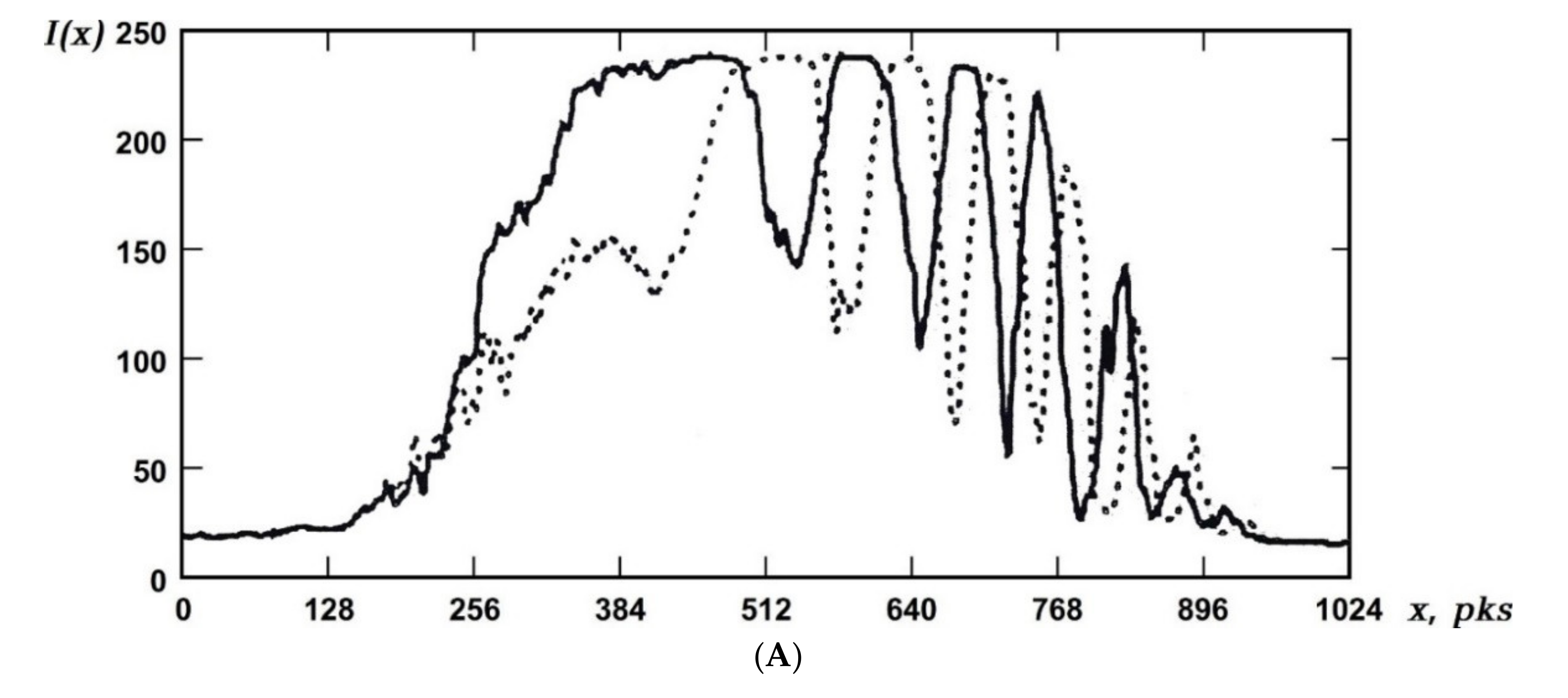
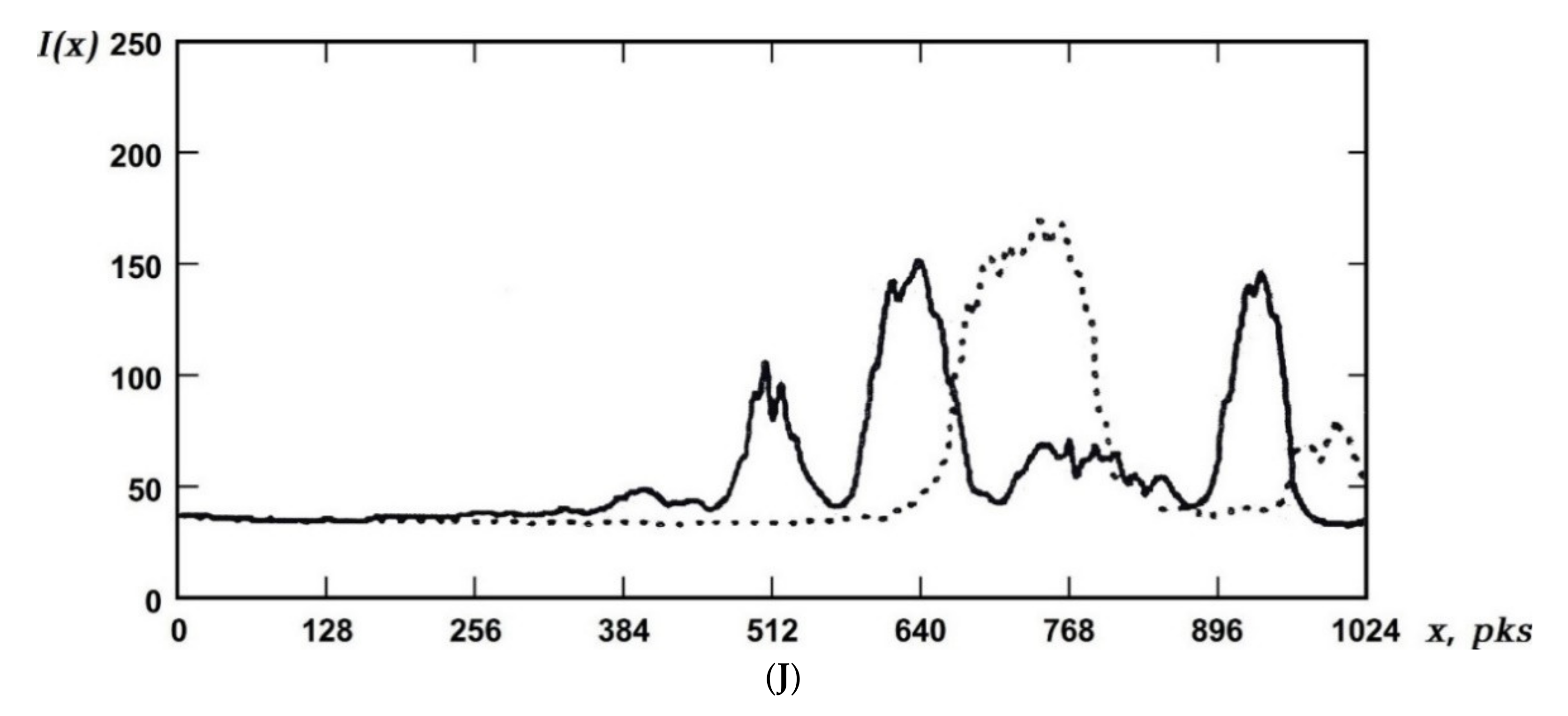
Figure 4 shows the marked dependencies for each of the modeling options (see
Table 1) along the
x-axis (see
Figure 3), and these are displayed pairwise for the values of the variables
y0 and
y0 + Δ
ys.
Figure 4 shows the following notations: 1
pks = 0.00015 m; the solid curve corresponds to the distance
y0 (see
Table 1) between the surfaces of the reflector (3) (the simulator of the control object’s surface) and the beam-splitter (4), and the dotted curve corresponds to the distance
y0 + Δ
ys, at which there is a complete change in the intensity in the rings of the interference pattern from the minimum to the maximum value, and vice versa.
The analysis of the obtained results and a comparative analysis of them with the results published earlier in well-known references have been carried out.
The analysis of the results presented in
Figure 4 allows one to note that the maximum intensity values occur in the rings of interference patterns close to their center, and with increasing spacing,
y0, (that is, when the sensitivity of the setup under study decreases with an increase in the radius of curvature of the radiation wavefront) the amplitude of the intensity of the interference pattern and the contrast decreases. The practical measurement problems should be solved by using photodetector devices with a limited aperture.
The most informative and highly contrasted area is that of the interference pattern in the horizontal section (along the
x-axis) from the edge of the interference pattern opposite the vertex of the angle
α between the beam splitter and the reflector to the center of the interference pattern (see
Figure 1,
Figure 2 and
Figure 4). This is true for all the considered values of
y0 (modeling variants), and is also completely consistent with the results given in [
37]. Based on this, it should be noted that it is most appropriate to use photodetectors with a limited aperture, or to register changes in the intensity of the optical field of the interference pattern (for photodetector arrays), from the viewpoint of the measurement quality in this marked area of the interference pattern. This recommendation should be taken into account when solving practical measurement problems, regardless of the design of the photodetector devices.
The analysis of the obtained results also showed that, with an increase in the distance,
y0, between the control object’s surface and the beam-splitter, the spatial frequency of the interference pattern and the sensitivity decrease (see
Figure 4). This conclusion is in full agreement with the results published in [
33]. It also corresponds to the results of the computational and theoretical study published in [
30], and is explained by an increase in the radius of curvature of the radiation wavefront.
Figure 5 shows the dependence of the change in the displacement, Δ
ys, on the distance,
y0 (see
Table 1), obtained in the result of this experimental study. This dependence has practical significance for solving various measurement problems. It reduces the time required for preparing measurements on the basis of providing the possibility of an
a priori estimation of the displacement, Δ
ys, at the distance
y0 when setting up the device for measurements.
The experimental studies described above were carried out at a value of the angle of the radiation incident on the surface of the control object
α0 = 5° (see
Figure 1 and
Figure 2).
However, by solving the applied (practical) measurement problems, it is not always possible to provide this value of the angle α0. With various design features of the objects of control, the value of the angle α0 could be changed quite significantly. This is confirmed, for example, by the experimental operation of the investigated setup.
In well-known publications, studies of the effect of the angle α0 (when differing from 5°) on the sensitivity of the setup under study and, respectively, on the measurement results, were not carried out. However, the availability of the results of such studies is relevant and important for solving the applied (practical) measurement problems.
Experimental studies of the features of the investigated setup at significantly different values of the angle
α0 of the radiation incidence on the surface of the control object have been carried out (see
Figure 1 and
Figure 2) at
α0 = 25° and 45°.
The methodologies of these studies fully corresponded to that described above for the angle of the radiation incident on the control object surface, α0 = 5°.
The results obtained, and their comparison with the results obtained for the value of angle α0 = 5°, allow us to conclude that the sensitivity of the setup studied does not depend on the angle α0 at a constant spacing y0 between the surface of the object of control and the beam-splitter.
This result should also be taken into account when solving practical measurement problems.
5. Conclusions
Test studies of the functionality of a prospective optical setup for measuring the surface linear displacements of control objects were carried out for various possibilities of the geometric characteristics of the optical scheme. This device was developed on the basis of an interference measurement method, namely, the “luminous point” method.
The developed method of performing experimental studies consisted in a sequential step-by-step simulation of the linear displacement of the simulator of the control object’s surface in the direction of the beam-splitter. In this way, the digital images of interference patterns containing information about the intensity of the optical field throughout the interference pattern were registered. This registration was implemented at each step of the simulation for each of the considered modeling options until a complete change was achieved in the intensity of the rings of the interference pattern from the minimum to the maximum value, and vice versa.
The processing of the obtained digital images of interference patterns was carried out using the original registered computer programs.
The results of the experimental study regarded the dependences of the change in the intensity of the optical field of interference patterns obtained at each step of the simulation and for each of the modeling options.
The analysis of the obtained results allows us to note that maximum intensity takes place in the interference pattern rings closest to their center. The most informative and highly contrasted area is that of the interference pattern in the horizontal section, ranging from the edge of the interference pattern, opposite to the vertex of the angle between the beam-splitter and the reflector, to the center of the interference pattern, and this is true for all modeling options.
It is also experimentally confirmed that with significant changes in the angle of radiation incidence on the surface of the control object, the sensitivity of the studied setup does not change.
These results should be taken into account when solving practical measurement problems.
The noted research results are most appropriate for use in the development of new contactless optical devices for measuring the displacements of control object’s surfaces and in various test procedures in the research and development of machines and equipment, as well as in the diagnostics of the state of construction materials and power elements of different equipments during their operation.


