Article

Effect of Temperature on the Microwave-Absorbing Properties of an Al2O3–MoSi2 Coating Mixed with Copper

1
College of Materials Science and Engineering, Yanshan University, No. 438 West Hebei Avenue, Qinhuangdao 066004, China
2
School of Mechanical and Electrical Engineering, Guilin University of Electronic Technology, No. 1 of Jinji Road, Guilin 541004, China
*
Author to whom correspondence should be addressed.
Coatings 2021, 11(8), 940; https://doi.org/10.3390/coatings11080940
Submission received: 22 June 2021 / Revised: 28 July 2021 / Accepted: 3 August 2021 / Published: 5 August 2021

Abstract

:
To obtain a high temperature-resistant microwave absorbing coating, an Al2O3–MoSi2/Cu composite coating was prepared by atmospheric plasma spraying. Compared with a normal temperature environment, there are a few reports on Cu as an absorbent for high temperature microwave absorbing coatings. Therefore, in this regard, wave absorbing property can be improved by using a Cu absorbent. The microstructure of a Al2O3–MoSi2/Cu coating was observed, and the dielectric properties of the composite coating in the high-temperature environment of the X-band were tested. The experimental results show that with the increase in temperature, Cu transforms Cu2O in the high-temperature environment and improves the coating’s wave absorption performance with MoSi2. In addition, a 1.4 mm-thick coating showed best microwave absorbing performance at 700 °C. The reflection loss was −19.09 dB, and the effective microwave absorbing bandwidth was 2.83 GHz (Reflection Loss < −10 dB). It was found that the Al2O3–MoSi2/Cu composite coating has good wave-absorbing performance in a 700 °C high-temperature environment.

1. Introduction

Recent studies have shown that due to radar detection technology’s rapid development, an increasing amount of attention has been paid to radar stealth technology research. Meanwhile, an increasing number of researchers have investigated high-temperature microwave absorbing materials [1,2,3,4,5,6,7,8,9]. The high-temperature absorbing coating prepared by the plasma spraying method has good absorbing performance [10,11,12,13]. Al2O3 and MoSi2 are widely used in high-temperature resistant coatings due to their excellent high-temperature resistance [14,15,16]; Cu is rarely studied in a high-temperature environment as an absorbing material.
As an electromagnetic wave absorber, MoSi2 powder has certain characteristics—high melting point, low relative density, and excellent high-temperature oxidation resistance—and is widely used in high temperature-resistant coating materials, composite materials, and high temperature-resistant structures [17]. Researchers have carried out in-depth studies on the wave absorption performance and high-temperature oxidation of MoSi2. This research used MoSi2–30Al2O3 as raw a material, prepared a MoSi2–Al2O3 electrothermal coating by atmospheric plasma spraying, and studied the electrothermal properties of the composite coating [18]. Shang et al. [19] prepared MoSi2/BC porous composite microwave absorbing material by the solid-phase sintering method and found that it had good absorbing performance. When the MoSi2/BC mass fraction was 50%, the reflection loss was the lowest; the effective absorption bandwidth of the microwave absorbing material was approximately 1.0 GHz, and the reflection loss was −13 dB. Jiao et al. [20] prepared a MoSi2-CoNiCrAlY composite coating on the surface of a GH4169 alloy, and studied the cyclic oxidation behavior of the composite coating under a 900 °C static atmosphere environment; they found that the composite coating has good high-temperature oxidation resistance. Wu et al. [21] prepared MoSi2/Al2O3 coatings with different MoSi2 contents by atmospheric plasma spraying; it was found that with the increase in MoSi2 content, the electrical conductivity and dielectric loss of the coatings also increased.
Cu is an electromagnetic shielding material. Its electromagnetic shielding performance has been widely studied; it has good conductivity and wear resistance, and can thus be used as an effective absorbent in coatings. However, for the preparation of mixed high temperature-resistant microwave absorbing coatings, research is rare. Moustafa et al. [22] prepared copper–graphite composite materials with different graphite contents by powder metallurgy metohes and copper coating on graphite powder by the electroless coating technique. The results show that the graphite powder made by the two metohes has a lower wear rate and friction coefficient. Sun et al. [23] used the micro-arc discharge method for the synthesis of a carbon-coated copper nanocapsule made with Cu nanocapsule as the core and carbon absorbing material as the shell of the core-shell structure; the study found that the thickness of 1.9 mm of the carbon-coated copper nanocapsule and a reflection loss of −40 dB was achieved at 10.52 GHz. The carbon-coated copper nanocapsule has excellent absorbing performance. Zhao et al. [24], through a simple solution reduction method, made a new leaf-like NiCu alloy composite. The experiment discovered that 40 wt.% of NiCu has good microwave absorbing performance, since reflection loss reached −21.1 dB, and the microwave absorption bandwidth was 3.4 GHz.
In this research, both Al2O3 and MoSi2 have good high-temperature stability and can be used in temperature environments. Therefore, an Al2O3–MoSi2 composite coating was used as the substrate, and Cu particles were sprayed onto the surface of the Al2O3–MoSi2 composite coating by plasma spraying. Cu in high-temperature microwave absorbing coatings is rarely studied; however, it has a lot of research value. In high-temperature environments with sufficient O2, Cu is transformed into CuO [25] and Cu2O [26], and the copper oxide formed by Cu transformation will improve the wave absorbing performance of the Al2O3–MoSi2/Cu composite coating. An Al2O3–MoSi2/Cu composite high-temperature absorbing coating was successfully prepared by atmospheric plasma spraying. The microstructure, composition, and dielectric properties of the Al2O3–MoSi2/Cu composite coatings at different temperatures were summarized, and the wave absorption properties of three thickness coatings were researched at different temperatures. Therefore, this research provides a new insight into the preparation of high-temperature absorbing coatings.

2. Materials and Methods

An Al2O3–MoSi2/Cu coating was prepared by the atmospheric plasma spraying method, and its high temperature microwave absorbing performance tested in the X-band. After the coating was finished by plasma spraying, the coating sample was cut into the size required by the instrument test. It was analyzed by X-ray diffraction (XRD, D8-Advance, Bruker, Bremen, Germany, Cu–Kα radiation). The microstructure of the coating surface was observed by a scanning electron microscope (SEM, Quanta 450 FEG, FEI Company, Hillsboro, OR, USA), and the high-temperature electromagnetic and wave absorption properties of the coating were measured by a vector network analyzer (Agilent E8363B PNA, Santa Clara, CA, USA).

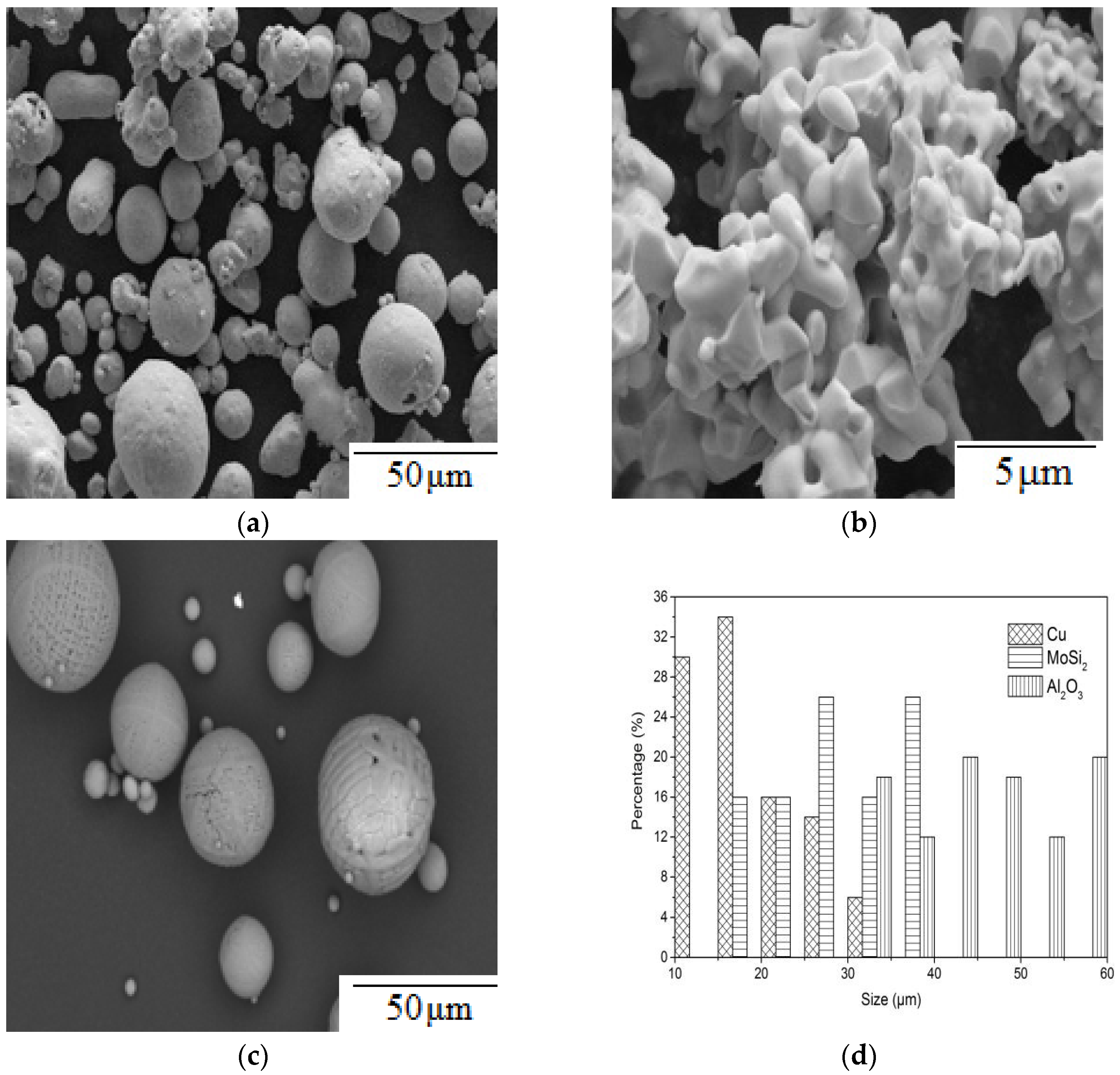
2.1. Preparation of Spraying Feedstock

MoSi2 powder was produced by Shanghai Naiou Nanotechnology Co., Ltd. (Shanghai, China). The powder size was between 15 and 40 μm, and the shape of MoSi2 was irregular. Cu particles were produced by Shanghai Naiou Nano Technology Co., Ltd. (Shanghai, China). The size of Cu powder particles was different, with the large particle size ranging from 20 to 35 μm and the small particle size ranging from 10 to 15 μm. Al2O3 powder was produced by Shanghai Xiangtian Nanomaterials Co., Ltd. (Shanghai, China). The particle size of the powder was 30~60 μm. MoSi2 powder, Cu powder, and Al2O3 powder are all micron powder, and micron-sized powder can be used to make the powder mixture uniform and powder feeding uniform in the spraying process. The raw powder content information is shown in Table 1.
To mix Al2O3 and MoSi2, the ball mill method was used at a speed of 380 r/min for 3.5 h, and appropriate alcohol was added. After ball milling, the mixed powder solution was poured into the container, placed into a blower, and the drying temperature was set at 90 °C. The Al2O3–MoSi2 (80 wt% Al2O3 + 20 wt% MoSi2) mixed powder was dried via an air dryer and grinded into a uniform and delicate powder using a mortar. The preparation process of Cu powder is the same as that of the Al2O3–MoSi2 mixed powder. The mix powder phase of the samples was determined by X-ray diffraction in the 2θ range from 20 to 80°.

2.2. Plasma Spraying Experiment

Before plasma spraying, the substrate had to be pretreated, which included two processes: oil removal and sandblasting. The plasma spraying equipment included the SX-80, produced by Guangdong Sanxin Company (Guangzhou, China). In the spraying process, Al2O3–MoSi2 mixed particles are first sprayed on the substrate. After the preparation of the Al2O3–MoSi2 composite coating, 0.05 mm-thick Cu particles were sprayed onto the surface of the Al2O3–MoSi2 coating. Ar was used as the main gas in plasma spraying as Ar is an inert gas that has an excellent protective effect on spraying particles, and Ar has a lower enthalpy and a faster temperature rise. H2 is mainly used as a secondary gas. H2 has excellent heat transferability, which is conducive to the refractory powder’s melting and can prevent the spraying powder’s oxidation. An SEM micrograph of the Al2O3–MoSi2/Cu composite coating is shown in Figure 1, and the plasma spraying parameter settings are shown in Table 2.

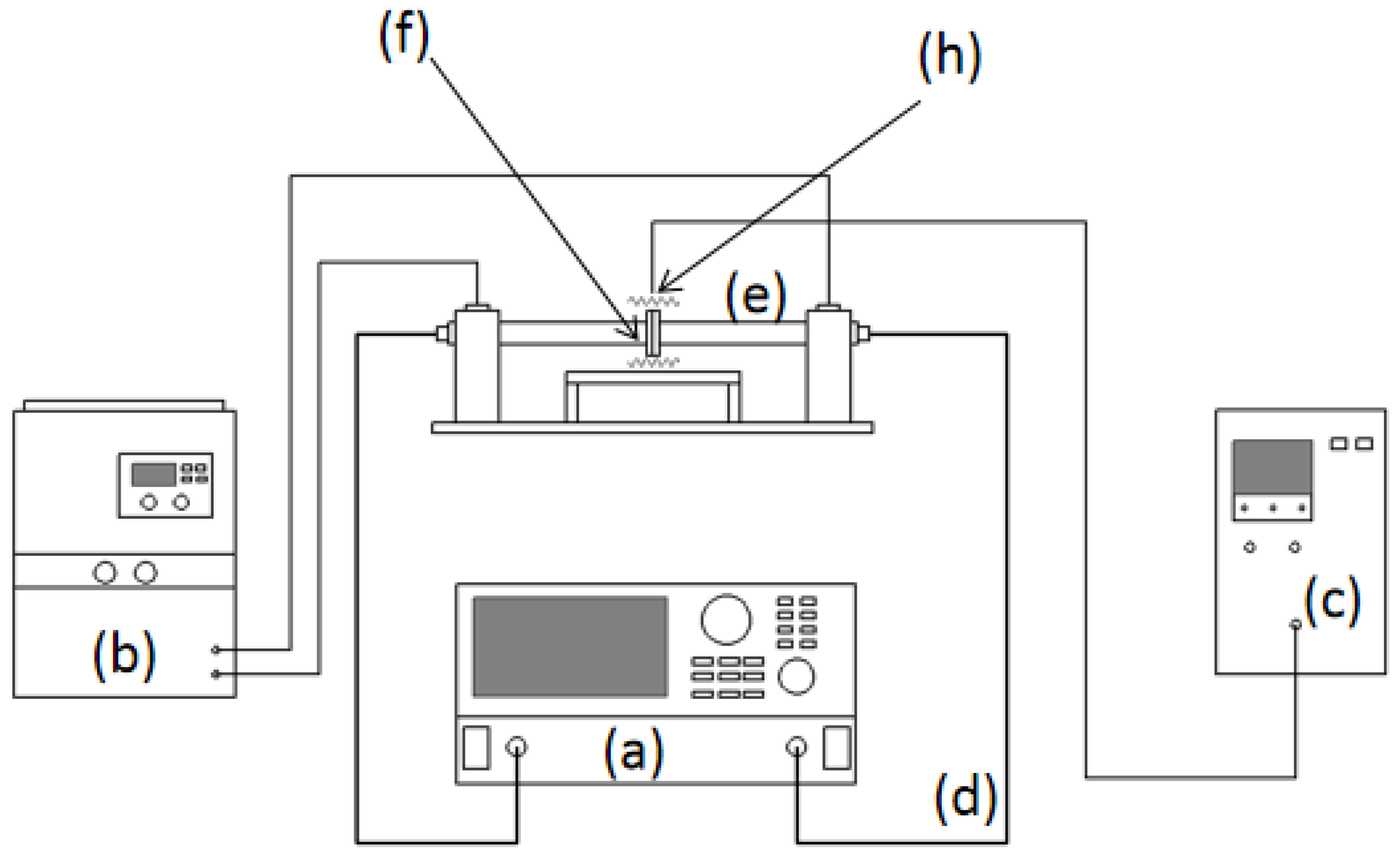
2.3. Dielectric Properties of the Coating

The Agilent E8363B PNA series vector network analyzer was used for the high-temperature wave absorption test. The electromagnetic parameters of the samples were tested by the wave-guide method [27] in the frequency range of 8.2 GHz–12.4 GHz (X-band). Before the test, the coating was cut into the sample holder with dimensions of 22.86 mm × 10.16 mm × 2 mm (X-band sample size); if the coating sample needed to be heated to more than 100 °C, heat preservation was done at 100 °C for 2 h, and then the dielectric constant of the coating was tested by E8363B from 25 °C to 700 °C in the X-band. The temperature of the waveguide increased at a rate of 10 °C per minute, monitored by a thermostat and software. The high temperature electromagnetic parameter test system is show in Figure 2.
The Al2O3–MoSi2/Cu coating is a dielectric microwave absorbing material, and its complex dielectric constant can be calculated by Equation (1) [28]:
εr = ε′ −
The reflection loss dB of the coating can be calculated by transmission line theory Equation (2) [29] and Equation (3) [30]:
R = 20 lg Z in Z 0 Z in + Z 0
Z in = Z 0 μ r ε r tanh j 2 π f d c μ r ε r
where εr of Equation (1) represents the complex dielectric constant of the material. Z0 represents the air impedance of the microwave absorbing material, and Zin represents the material’s input impedance. In the formula, f represents the frequency of the electromagnetic wave, d represents the thickness of the material, c represents the speed of the electromagnetic wave upropagation under vacuum, and j is an imaginary unit. Al2O3–MoSi2/Cu is a pure dielectric material, so μr in the formula is 1.

3. Results and Discussion

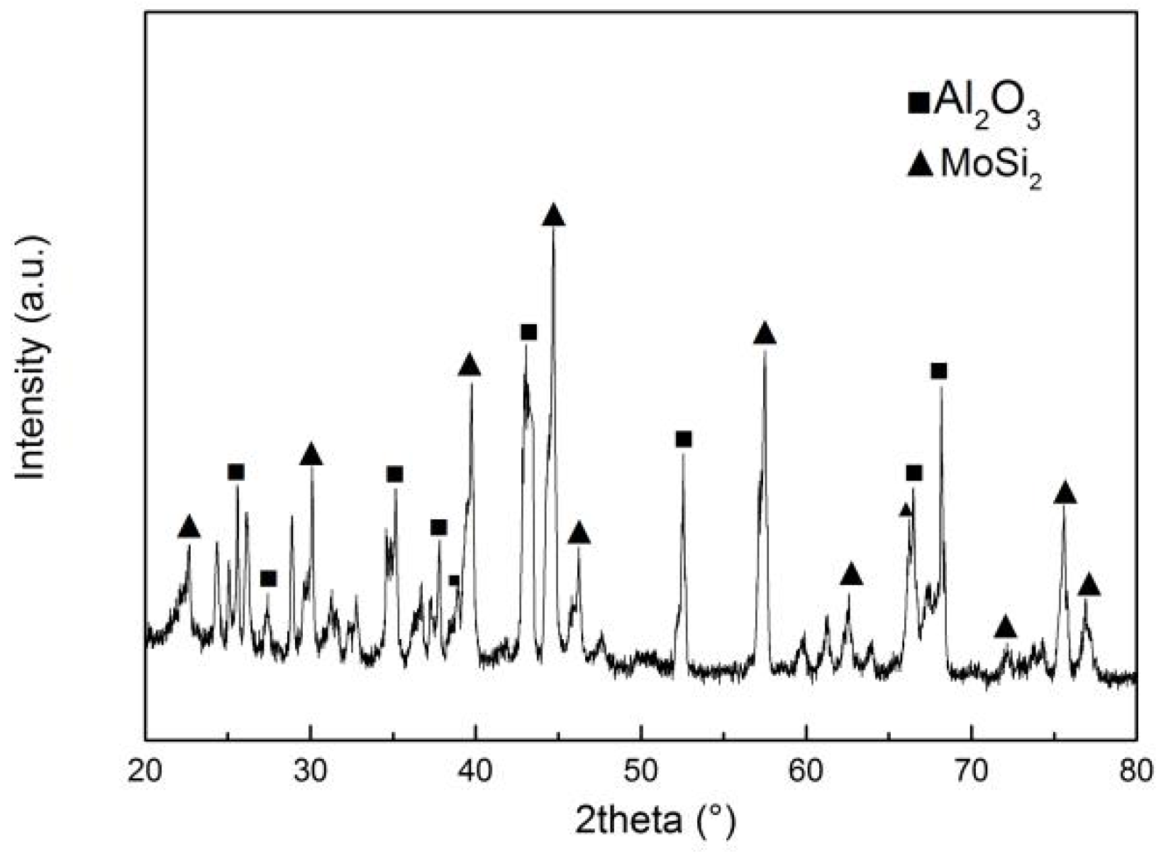
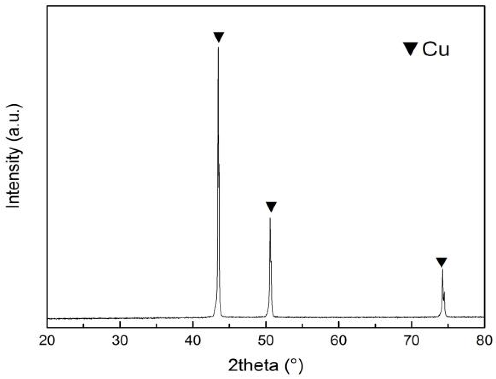
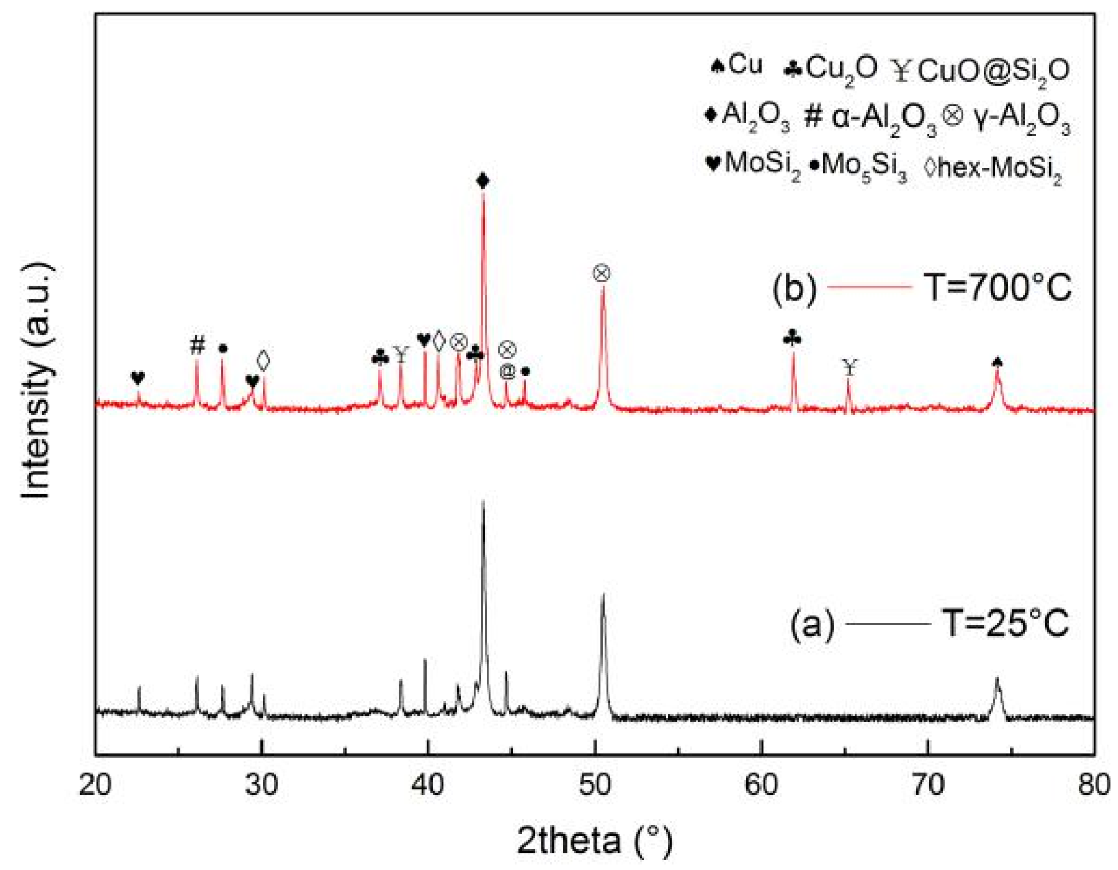
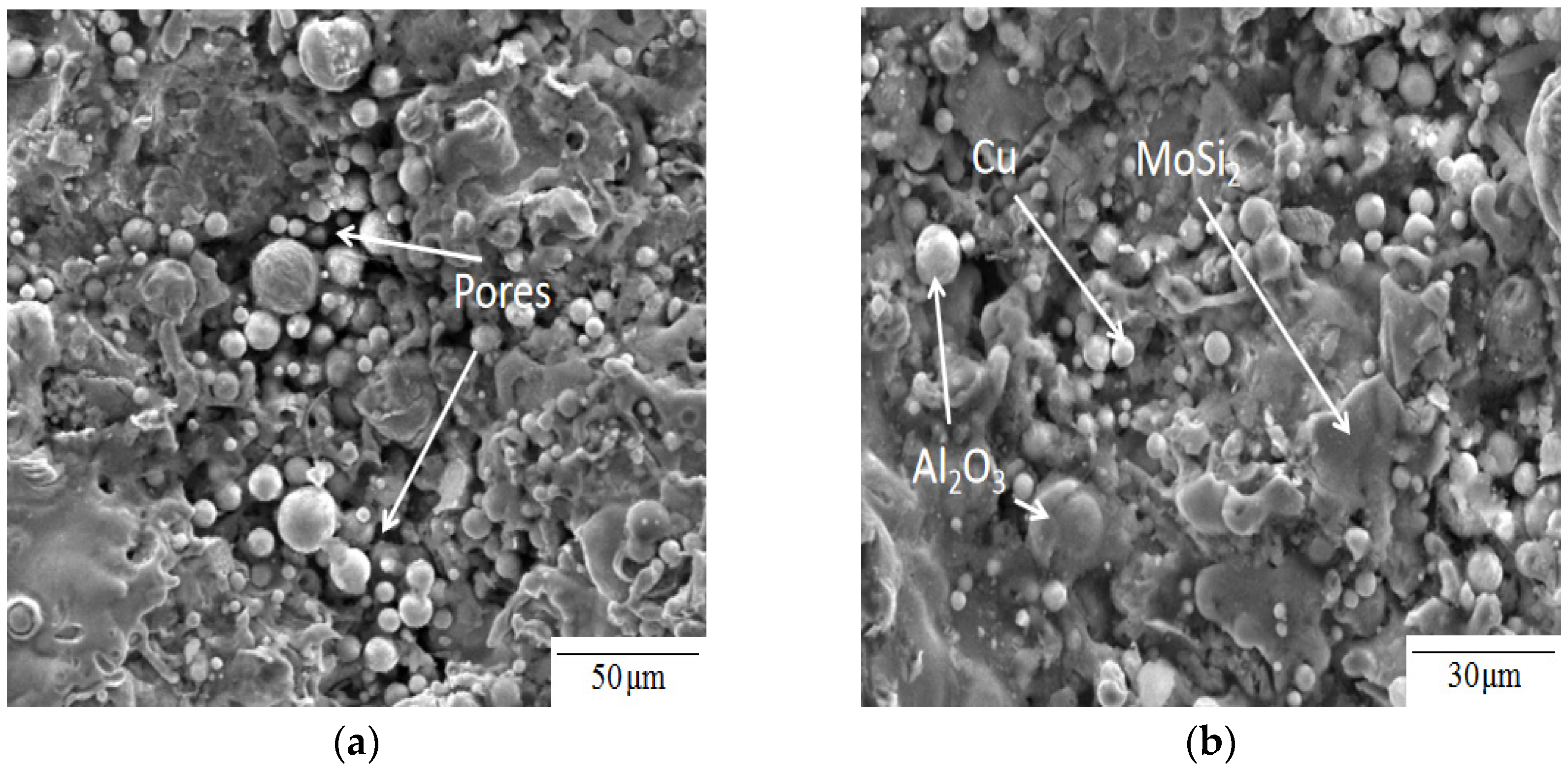
3.1. Microstructure of the Coating

The XRD analysis of the Al2O3–MoSi2 powder is shown in Figure 3. It can be seen from the figure that the XRD of the particles is composed of MoSi2 and α-Al2O3, with many peaks of different degrees; the strongest peak is MoSi2. A new α-Al2O3 phase was produced in the process of preparing Al2O3–MoSi2 powder by ball milling. In addition, there were no new compounds. The XRD analysis of the Cu powder is shown in Figure 4. It can be seen from the figure that the peak of Cu is very sharp, and there is no peak of other elements, so the purity of the Cu powder is very high.
The XRD analysis of the Al2O3–MoSi2/Cu composite coating is shown in Figure 5a. The coating is mainly composed of Al, O, Si, Mo, and Cu. By comparing the XRD of the powder and the coating, it can be seen that new phases of MoSi2 and Cu are formed. The coating surface comprises of seven phases: MoSi2, Hex–MoSi2, Mo5Si3, α-Al2O3, γ–Al2O3, Cu, and Cu2O. The sharpest peaks are Cu and α-Al2O3, with different strength peaks caused by the powder’s high temperature and oxidation during the plasma spraying. A small amount of new Cu2O phase appeared in the coating as a small amount of oxygen entered the plasma flame during the spraying process, and part of the Cu powder was oxidized during the accelerated melting process, generating a Cu2O new phase [31]. A small amount of Mo5Si3 and Hep–MoSi2 appeared in the coating as MoSi2 was mixed with a small amount of oxygen in the plasma spraying process [32]. The experiments show that the addition of Al2O3 to MoSi2 could change the resistivity and low-temperature oxidation resistance of MoSi2 [33]. This “pesting” is a coating defect as MoSi2 at 400~600 °C causes a phenomenon that transforms the material into powder; the addition of Al2O3 can prevent the rapid oxidation of the MoSi2 phenomenon [34]. In the XRD analysis, the Al2O3–MoSi2/Cu composite coating was heated at 700 °C and heat preservation for 0.5 h is shown in Figure 5b. CuO and SiO2 appeared on the composite coating surface at 700 °C. CuO was produced as in the full reaction of Cu2O with O2; Cu2O (inner layer) slowly converted to CuO (coating surface) [35]. SiO2 generation is the full reaction of MoSi2 with O2.
Figure 6 shows the SEM micrograph of the Al2O3–MoSi2/Cu composite coating. It can be clearly seen that Cu, Al2O3, and MoSi2 particles are irregularly distributed on the coating surface, while there are a few pores on the coating surface.

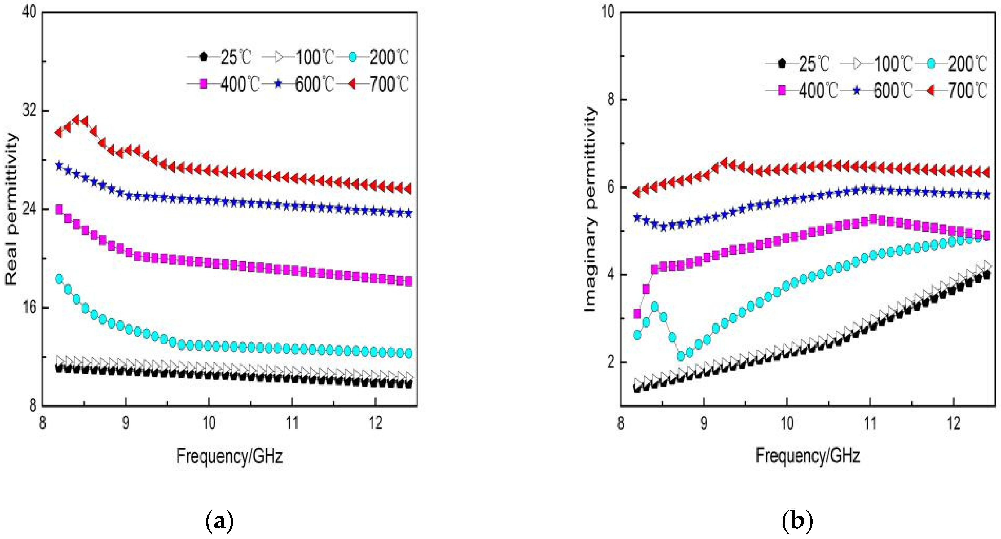
3.2. Dielectric Properties of the Coating

As shown in Figure 7, the ε′ and ε″ of the coating increased with the increase in temperature. The ε′ and ε″ of the coating are 10.23 and 2.11 at 25 °C, 13.1 and 3.55 at 200 °C, and 22.4 and 5.09 at 500 °C, respectively. The dielectric constant of the Al2O3–MoSi2/Cu coating changed with the increase in temperature. It can be seen from Figure 7a that the ε′ increased with the increase in temperature. At two different temperature ranges in 200 °C and 600 °C, we can find that the ε′ gradually moved to the high-frequency range. ε′ at a high temperature can be expressed by Debye’s theory in Equation (4) [36]:
ε = ε + ε S ε 1 + ω τ ( T ) 2
where ε is the limit value of the permittivity changing with the increase in ω, εS is the static permittivity, and τ(T) is the relaxation period. The relationship between relaxation time and temperature can be expressed by the Arrhenius formula in Equation (5) [37]:
τ ( T ) = τ 0 exp ( E a R T 0 )
where Ea is the activation energy, τ0 is the pre-factor, and T0 is the temperature. R is Avogadro’s constant.
As shown in Figure 7b, ε″ also increases with the material temperature. The material was tested at two different temperatures of 200 and 600 °C, showing that the higher the temperature, the lower the relaxation time. At a high temperature, ε″ can be expressed in Equation (6) [36]:
ε = ε + ( ε S ε ) ω τ ( T ) 1 + ω 2 ω τ ( T ) 2 + σ ( T ) ω ε 0
where σ(T) is the conductivity of the medium, and the ε′ and ε″ of the Al2O3–MoSi2/Cu increased gradually with the increase in temperature. ε′ moved from the low-frequency region to the high-frequency region with increased temperature, and ε′ decreased with the frequency increase. This phenomenon is called the dispersion effect [38]. This may be due to the formation of a conductive network between MoSi2 and Al2O3 [39], and the increase in temperature led to an increase in the conductivity of Al2O3–MoSi2/Cu and the enhancement of conduction loss. ε″ moved from the low-frequency region to the high-frequency region with the increase in temperature. The main effect is that the increase in temperature led to the coating’s improved electrical conductivity [40]. Additionally, it can be seen from Figure 6 that the relaxation time became shorter as the temperature increased and that the real and imaginary parts of the complex dielectric constant of the Al2O3–MoSi2/Cu coating were lower at 25 °C. The Al2O3–MoSi2/Cu coating has remarkable dielectric properties at high temperatures.

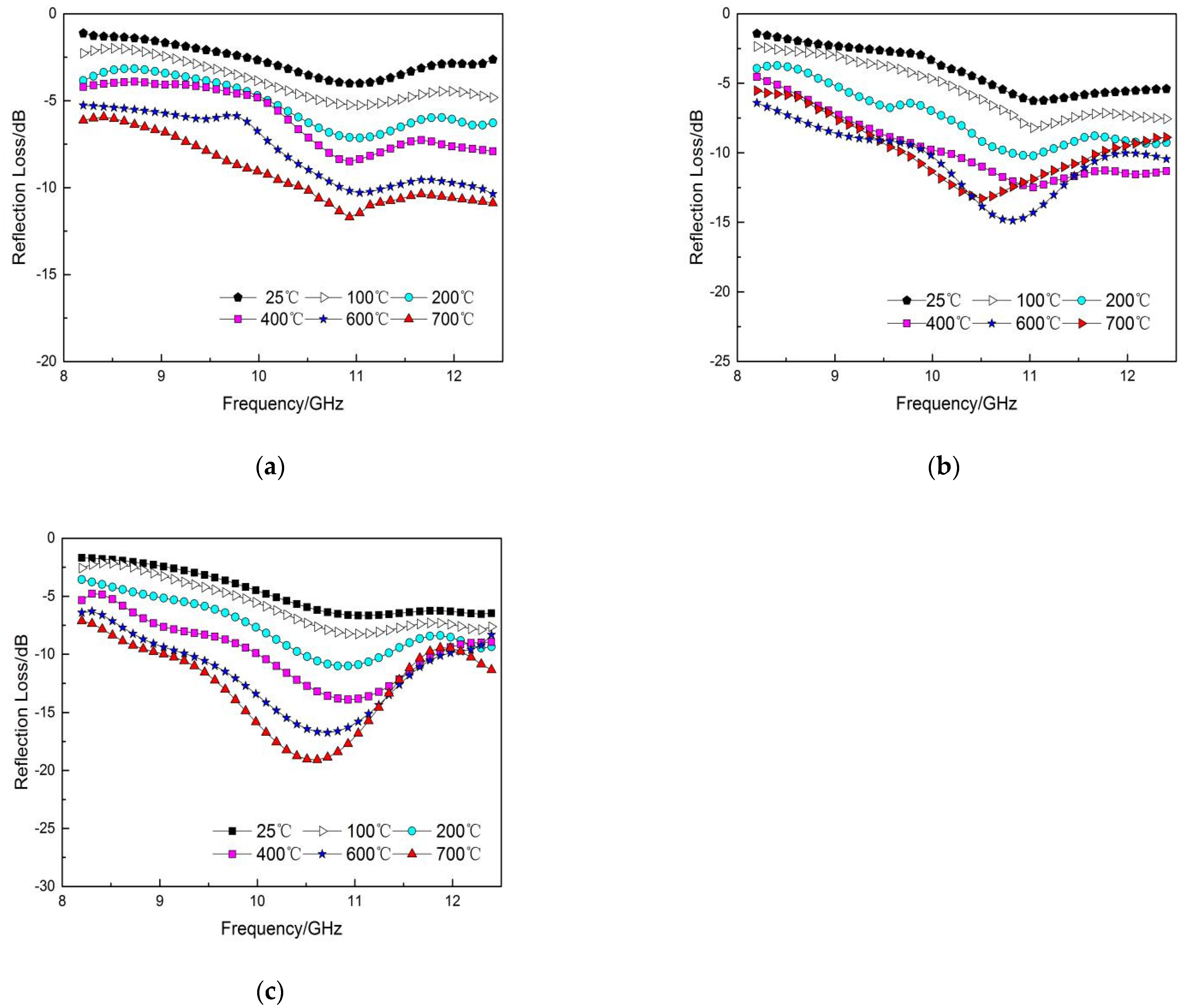
3.3. Absorbing Performance of the Coating

The wave absorption performances of the coatings are shown in Figure 8. According to transmission line theory Equations (2) and (3), the absorption peak frequency of the 1.0 mm-thick coating was 11 GHz, and the reflection loss was −11.69 dB. When the coating reached 700 °C, the wave absorption performance was the best. The lowest of the 1.2 mm coating frequency was 10.8 GHz, and the reflection loss was −14.87 dB. When the coating’s temperature reached 700 °C, the wave absorption performance was the best. The thickness of the coating was 1.4 mm, the frequency of the best absorption performance was in 10.51 GHz, the reflection loss was −19.09 dB, and the absorption performance was the best when the temperature reached 700 °C. It can be seen that the Al2O3–MoSi2/Cu coating has good high-temperature wave absorbing performance.
With the increase in coating thickness, the wave absorption performance of the Al2O3-MoSi2/Cu coating gradually increased. The coating’s thickness was 1.0 mm, reflection loss was −3.99 dB, absorbing performance was weak at room temperature (25 °C), absorption frequency was at 11 GHz, the coating’s reflection loss was −11.69 dB, and the temperature was 700 °C. When the thickness of the Al2O3–MoSi2/Cu coating was 1.4 mm, the coating’s minimum reflection loss was −6.66 dB at 25 °C, and the reflection loss of the coating was −19.09 dB at 700 °C. As can be seen from Figure 8c, the coating thickness is 1.4 mm, the reflection absorption frequency gradually moved to the left as the coating temperature increased, which can be explained by Equation (7) [41]. When the coating thickness was the same, the value of ε′ increased with the increase in temperature, which moved the frequency band of the interference from high frequency to low frequency so that the coating reached the role of broadband absorption. Parts of the wave-absorbing performance of the coatings are shown in Table 3.
f m = c 4 d ε r
where fm is the matching frequency, c is the speed of light in vacuum, and d is the thickness of the coating.
Cu is often used in electromagnetic shielding material and has good conductivity. The Al2O3–MoSi2/Cu composite coating does not have good wave absorption performance at room temperature (25 °C) due to the addition of Cu, the coating thickness is 1 mm with with a minimum reflection loss of −3.9 dB, as shown in Table 3. According to the XRD pattern in Figure 5, with the increase in temperature, Cu was gradually transformed into Cu2O, and in a sufficient O2 environment, Cu2O was transformed into CuO in the process of heating up in the 700 °C heat preservation test. It can be seen from report [26] that Cu2O plays a role in improving the absorbing performance of the coating, which is mainly attributed to the conductive network formed by Cu2O with the increase in temperature. Cu2O exists on the inner layer of the coating together with Al2O3–MoSi2 to increase the electrical conductivity of the coating, which enhances the wave-absorption performance of the coating. In Figure 8c, the coating thickness is 1.4 mm, the minimum reflection loss at 25 °C is only −6.66 dB, but min RL at 700 °C is 19.09 dB. It can be seen from Figure 8 that with the increase in temperature, the coating gradually has good absorbing performance. Specifically, the Cu is transformed into CuO and Cu2O improves the electrical conductivity of the coating, and improves the wave-absorbing performance of the coating.
The experimental results show that the Al2O3–MoSi2/Cu absorbing coating by plasma spraying in this work is a new type of absorbing coating used at high temperature, and copper oxide has an influence on the absorbing performance of the coating. Therefore, compared to other wave absorbing coatings, the Al2O3–MoSi2/Cu coating’s wave absorption performance is not obvious at room temperature of 25 °C, but it has good wave absorption performance at high temperatures of 700 °C. The characteristics of wave-absorbing performance with temperature variation deserve attention in future.

4. Conclusions

The results show that the wave absorption performance of the Al2O3–MoSi2/Cu composite high temperature-resistant coating is gradually enhanced with the increase in temperature. This study conducted the XRD analysis of mixed powder elements and composite coating compounds, and SEM to observe the structure of the composite coating. The SEM micrograph showed that copper oxide exists on the coating surface. The vector network analyzer measured the dielectric properties and calculated Reflection Loss under different temperatures. It was found that Cu2O formed by Cu at high temperatures can enhance the coating’s absorbing properties. Coating thickness was 1.4 mm with the best reflection loss. The coating’s reflection loss was −19.09 dB at a temperature of 700 °C and frequency of 10.5 GHz. The results show that the coating has a good high-temperature microwave absorbing performance in the X-band.

Author Contributions

Conceptualization, C.G. and W.X.; methodology, C.G.; formal analysis, Y.J.; investigation, C.G.; data curation, W.X.; writing—original draft preparation, C.G. and Y.J.; writing—review and editing, D.C.; visualization, Y.J.; supervision, D.C.; project administration, J.X.; funding acquisition, J.X. All authors have read and agreed to the published version of the manuscript.

Funding

Guangxi S & T Program (No. AD18126024).

Institutional Review Board Statement

Not applicable.

Informed Consent Statement

Not applicable.

Data Availability Statement

Data is included in this article.

Conflicts of Interest

The authors declare no conflict of interest.

References

  1. Liu, H.; Tian, H.; Cheng, H. Dielectric properties of SiC fiber-reinforced SiC matrix composites in the temperature range from 25 to 700 °C at frequencies between 8.2 and 18 GHz. J. Nucl. Mater. 2013, 432, 57–60. [Google Scholar] [CrossRef]
  2. Gao, H.; Luo, F.; Wen, Q.; Jia, H.; Zhou, W.; Zhu, D. Enhanced high-temperature dielectric and microwave absorption properties of SiC fiber-reinforced oxide matrix composites. J. Appl. Polym. Sci. 2018, 136, 47097. [Google Scholar] [CrossRef]
  3. Li, M.; Yin, X.; Zheng, G.; Chen, M.; Tao, M.; Cheng, L.; Zhang, L. High-temperature dielectric and microwave absorption properties of Si3N4–SiC/SiO2 composite ceramics. J. Mater. Sci. 2014, 50, 1478–1487. [Google Scholar] [CrossRef]
  4. Song, W.; Cao, M.-S.; Hou, Z.-L.; Yuan, J.; Fang, X.-Y. High-temperature microwave absorption and evolutionary behavior of multiwalled carbon nanotube nanocomposite. Scr. Mater. 2009, 61, 201–204. [Google Scholar] [CrossRef]
  5. Wan, F.; Yan, J.; Xu, H. Improved mechanical and high-temperature electromagnetic wave absorption properties of SiCf/BN/AlPO4 composites with absorber multiwalled carbon nanotubes. Compos. Interfaces 2020, 1–18. [Google Scholar] [CrossRef]
  6. Yuan, J.; Yang, H.-J.; Hou, Z.-L.; Song, W.; Xu, H.; Kang, Y.-Q.; Jin, H.-B.; Fang, X.-Y.; Cao, M.-S. Ni-decorated SiC powders: Enhanced high-temperature dielectric properties and microwave absorption performance. Powder Technol. 2013, 237, 309–313. [Google Scholar] [CrossRef]
  7. Mu, Y.; Zhou, W.; Hu, Y.; Wang, H.; Luo, F.; Ding, D.; Qing, Y. Temperature-dependent dielectric and microwave absorption properties of SiC /SiC–Al2O3 composites modified by thermal cross-linking procedure. J. Eur. Ceram. Soc. 2015, 35, 2991–3003. [Google Scholar] [CrossRef]
  8. Dou, Y.-K.; Li, J.B.; Fang, X.-Y.; Jin, H.-B.; Cao, M.-S. The enhanced polarization relaxation and excellent high-temperature dielectric properties of N-doped SiC. Appl. Phys. Lett. 2014, 104, 052102. [Google Scholar] [CrossRef]
  9. Micheli, D.; Marchetti, M.; Pastore, R.; Vricella, A.; Gradoni, G.; Moglie, F.; Primiani, V.M. Shielding effectiveness of carbon nanotube reinforced concrete composites by reverberation chamber measurements. In Proceedings of the International Conference on Electromagnetics in Advanced Applications (ICEAA), Torino, Italy, 7–11 September 2015. [Google Scholar]
  10. Chen, D.; Luo, F.; Zhou, W.; Zhu, D. Effect of Temperature on Microwave-Absorption Property of Plasma-Sprayed Ti3SiC2/NASICON Coating. J. Electron. Mater. 2019, 48, 1506–1510. [Google Scholar] [CrossRef]
  11. Zhou, L.; Chen, M.; Dong, Y.; Yuan, Z.; Johnson, D. Enhanced dielectric and microwave absorption properties of Cr/Al2O3 coatings deposited by low-power plasma spraying. J. Am. Ceram. Soc. 2016, 100, 620–626. [Google Scholar] [CrossRef]
  12. Jia, H.; Zhou, W.; Nan, H.; Qing, Y.; Luo, F.; Zhu, D. High temperature microwave absorbing properties of plasma sprayed La0.6Sr0.4FeO3-δ/MgAl2O4 composite ceramic coatings. Ceram. Int. 2020, 46, 6168–6173. [Google Scholar] [CrossRef]
  13. Su, J.; Zhou, W.; Liu, Y.; Qing, Y.; Luo, F.; Zhu, D. High-temperature dielectric and microwave absorption property of plasma sprayed Ti3SiC2/cordierite coatings. J. Mater. Sci. Mater. Electron. 2015, 27, 2460–2466. [Google Scholar] [CrossRef]
  14. Pastore, R.; Delfini, A.; Santoni, F.; Marchetti, M.; Albano, M.; Piergentili, F.; Matassa, R. Space Environment Exposure Effects on Ceramic Coating for Thermal Protection Systems. J. Spacecr. Rocket. 2021, 1–7. [Google Scholar] [CrossRef]
  15. Delfini, A.; Pastore, R.; Santoni, F.; Piergentili, F.; Albano, M.; Alifanov, O.; Budnik, S.; Morzhukhina, A.; Nenarokomov, A.; Titov, D.; et al. Thermal analysis of advanced plate structures based on ceramic coating on carbon/carbon substrates for aerospace Re-Entry Re-Useable systems. Acta Astronaut. 2021, 183, 153–161. [Google Scholar] [CrossRef]
  16. Huang, Z.; Zhou, W.; Tang, X.; Li, P.; Zhu, J. Dielectric and Mechanical Properties of MoSi2/Al2O3 Composites Prepared by Hot Pressing. J. Am. Ceram. Soc. 2010, 93, 3569–3572. [Google Scholar] [CrossRef]
  17. Wu, Z.-H.; Zhou, W.-C.; Luo, F.; Zhu, D.-M. Effect of MoSi2 content on dielectric and mechanical properties of MoSi2/Al2O3 composite coatings. Trans. Nonferrous Met. Soc. China 2012, 22, 111–116. [Google Scholar] [CrossRef]
  18. Zhou, Y.-Z.; Liu, M.; Yang, K.; Zeng, W.; Song, J.-B.; Deng, C.-M.; Deng, C.-G. Microstructure and Property of MoSi2-30Al2O3 Electrothermal Coating Prepared by Atmospheric Plasma Spraying. J. Inorg. Mater. 2019, 34, 646–652. [Google Scholar] [CrossRef] [Green Version]
  19. Shang, K.; Wu, Z.-H.; Zhang, L.-P.; Wang, Q.; Zheng, H.-K. Absorbing Performance of MoSi2/BC Composites Using Bamboo Charcoal Template. J. Mater. Eng. 2019, 47, 122–128. [Google Scholar] [CrossRef]
  20. Jiao, D.; Zhong, X.; Xu, W.; Qiu, W.; Liu, M.; Liu, Z.; Li, Z.; Zhang, G. High Temperature Oxidation Behavior of MoSi2-CoNiCrAlY Composite Coating Prepared by Plasma Spraying. Rare Met. Mater. Eng. 2019, 48, 1135–1141. [Google Scholar]
  21. Wu, Z.; Zhou, W.; Luo, F.; Zhu, D. Structure and Dielectric Properties of Alumina Coats Containing MoSi2-Particle Prepared by Atmosphere Plasma Spraying. Mater. Rep. 2011, 25, 63–65. [Google Scholar]
  22. Moustafa, S.; El-Badry, S.; Sanad, A.; Kieback, B. Friction and wear of copper–graphite composites made with Cu-coated and uncoated graphite powders. Wear 2002, 253, 699–710. [Google Scholar] [CrossRef]
  23. Sun, Y.; Feng, C.; Liu, X.; Or, S.W.; Jin, C. Synthesis, characterization and microwave absorption of carbon-coated Cu nanocapsules. Mater. Res. 2014, 17, 477–482. [Google Scholar] [CrossRef]
  24. Zhao, B.; Shao, G.; Fan, B.; Zhao, W.; Zhang, R. Preparation and electromagnetic wave absorption properties of novel dendrite-like NiCu alloy composite. RSC Adv. 2015, 5, 42587–42590. [Google Scholar] [CrossRef]
  25. Gao, S.; Zhou, N.; An, Q.; Xiao, Z.; Zhai, S.; Shi, Z. Facile solvothermal synthesis of novel hetero-structured CoNi–CuO composites with excellent microwave absorption performance. RSC Adv. 2017, 7, 43689–43699. [Google Scholar] [CrossRef] [Green Version]
  26. Gao, S.; Xing, H.; Li, Y.; Wang, H. Synthesis of Cu2O/multi-walled carbon nanotube hybrid material and its microwave absorption performance. Res. Chem. Intermed. 2018, 44, 3425–3435. [Google Scholar] [CrossRef]
  27. Micheli, D.; Pastore, R.; Vricella, A.; Delfini, A.; Marchetti, M.; Santoni, F. Electromagnetic Characterization of Materials by Vector Network Analyzer Experimental Setup. In Spectroscopic Methods for Nanomaterials Characterization; Elsevier: Amsterdam, The Netherlands, 2017; pp. 195–236. [Google Scholar]
  28. Singh, P.; Babbar, V.; Razdan, A.; Srivastava, S.; Puri, R. Complex permeability and permittivity, and microwave absorption studies of Ca(CoTi)xFe12−2xO19 hexaferrite composites in X-band microwave frequencies. Mater. Sci. Eng. B 1999, 67, 132–138. [Google Scholar] [CrossRef]
  29. Panwar, R.; Agarwala, V.; Singh, D. A cost effective solution for development of broadband radar absorbing material using electronic waste. Ceram. Int. 2015, 41, 2923–2930. [Google Scholar] [CrossRef]
  30. Chen, D.; Luo, F.; Zhou, W.; Zhu, D. Effect of Ti3SiC2 addition on microwave absorption property of plasma sprayed Ti3SiC2/NASICON coatings. J. Mater. Sci. Mater. Electron. 2018, 29, 13534–13540. [Google Scholar] [CrossRef]
  31. Ranjan, A.; Islam, A.; Pathak, M.; Khan, M.K.; Keshri, A.K. Plasma sprayed copper coatings for improved surface and mechanical properties. Vacuum 2019, 168, 108834. [Google Scholar] [CrossRef]
  32. Jin-Yuan, M.; Min, L.; Jie, M.; Chun-Min, D.; De-Chang, Z.; Lin, X. Oxidation-resistance of ZrB_2-MoS_2 Composite Coatings Prepared by Atmospheric Plasma Spraying. J. Inorg. Mater. 2015, 30, 282–286. [Google Scholar] [CrossRef]
  33. Wang, L.; Fu, Q.; Zhao, F. Improving oxidation resistance of MoSi2 coating by reinforced with Al2O3 whiskers. Intermetallics 2018, 94, 106–113. [Google Scholar] [CrossRef]
  34. Majumdar, S. Formation of MoSi2 and Al doped MoSi2 coatings on molybdenum base TZM (Mo–0.5Ti–0.1Zr–0.02C) alloy. Surf. Coatings Technol. 2012, 206, 3393–3398. [Google Scholar] [CrossRef]
  35. Ogbuji, L.U. Oxidation behavior of Cu–Cr environmental barrier coatings on Cu–8Cr–4Nb. Surf. Coat. Technol. 2005, 197, 327–335. [Google Scholar] [CrossRef]
  36. Cao, M.-S.; Song, W.; Hou, Z.-L.; Wen, B.; Yuan, J. The effects of temperature and frequency on the dielectric properties, electromagnetic interference shielding and microwave-absorption of short carbon fiber/silica composites. Carbon 2010, 48, 788–796. [Google Scholar] [CrossRef]
  37. Correia, N.T.; Ramos, J.J.M. On the cooperativity of the β-relaxation: A discussion based on dielectric relaxation and thermally stimulated depolarisation currents data. Phys. Chem. Chem. Phys. 2000, 2, 5712–5715. [Google Scholar] [CrossRef]
  38. Liu, Y.; Luo, F.; Zhou, W.; Zhu, D. Dielectric and microwave absorption properties of Ti3SiC2 powders. J. Alloys Compd. 2013, 576, 43–47. [Google Scholar] [CrossRef]
  39. Huang, Z.; Zhou, W.; Tang, X.; Zhu, J. Effects of milling methods on the dielectric and the mechanical properties of hot-pressed sintered MoSi2/Al2O3 composites. J. Alloys Compd. 2011, 509, 1920–1923. [Google Scholar] [CrossRef]
  40. Atwater, J.E.; Wheeler, R.R., Jr. Complex Permittivities and Dielectric Relaxation of Granular Activated Carbons at Microwave Frequencies between 0.2 and 26 GHz. Carbon 2003, 7, 1801–1807. [Google Scholar] [CrossRef]
  41. Shao, T.; Ma, H.; Wang, J.; Feng, M.; Yan, M.; Wang, J.; Yang, Z.; Zhou, Q.; Luo, H.; Qu, S. High temperature absorbing coatings with excellent performance combined Al2O3 and TiC material. J. Eur. Ceram. Soc. 2020, 40, 2013–2019. [Google Scholar] [CrossRef]
Figure 1. Three-elements distribution on the upper surface of the Al2O3–MoSi2/Cu coating and feedstock: (a) Cu; (b) MoSi2; (c) Al2O3; (d) the corresponding particle size distribution histograms of the Cu, MoSi2, and Al2O3 particles.
Coatings 11 00940 g001
Figure 2. High-temperature electromagnetic parameter test system: (a) Vector network analyzer; (b) Cooling system; (c) thermostat; (d) Coaxial line; (e) Rectangular waveguide; (f) Sample; (h) Thermocouple.
Coatings 11 00940 g002
Figure 3. X-ray diffraction of the Al2O3–MoSi2 mix powder.
Coatings 11 00940 g003
Figure 4. X-ray diffraction of the Cu powder.
Coatings 11 00940 g004
Figure 5. X-ray diffraction of the Al2O3–MoSi2/Cu composite coating surface: (a) T = 25 °C (b) T = 700 °C.
Coatings 11 00940 g005
Figure 6. SEM micrographs of the Al2O3–MoSi2/Cu coating upper surface: (a) some pores exist in the coating surface (b) MoSi2, Al2O3, and Cu particles.
Coatings 11 00940 g006
Figure 7. Dielectric properties of the Al2O3–MoSi2/Cu composite coating: (a) ε′ of the Al2O3–MoSi2/Cu composite coating; (b) ε″ of the Al2O3–MoSi2/Cu composite coating.
Coatings 11 00940 g007
Figure 8. Reflection loss of the Al2O3–MoSi2/Cu composite coatings: (a) d = 1 mm, (b) d = 1.2 mm, (c) d = 1.4 mm.
Coatings 11 00940 g008
Table 1. Al2O3–MoSi2 mix particles and Cu particles of feedstock materials (ωt. %).
PowderPurityMoCuSiFeNiFe2O3SiO2Others
MoSi299.964.50.0135.30.0010.002--Bal.
Al2O399.9-----0.050.05Bal.
Cu99.9-99.8-0.010.05--Bal.
Table 2. Atmosphere plasma spraying parameters.
ParametersValue
Arc Current (A)410
Arc Voltage (V)30
Primary gas (Ar) flow rate (L/h)2100
Secondary gas (H2) rate (L/h)10
Spray distance (mm)80
Powder carrier gas (Ar) flow rate (L/h)200
Powder feed rate (g/min)20
Table 3. Different coatings thickness at different temperatures, RL values, and bandwidth.
Thickness (mm)Temperature (°C)Minimum RL Values (dB)Effective Bandwidth (GHz)
(RL < −10 dB)
25−3.9-
1.0400−8.4-
700−11.691.78
25−6.2-
1.2400−12.482.19
700−14.872.42
25−6.66-
1.4400−13.891.68
700−19.092.83
Publisher’s Note: MDPI stays neutral with regard to jurisdictional claims in published maps and institutional affiliations.

