Article

Preparation and Properties of Multilayer Ca/P Bio-Ceramic Coating by Laser Cladding

1
College of Mechanical and Electrical Engineering, Central South University, Changsha 410083, China
2
State Key Laboratory of High Performance Complex Manufacturing, Changsha 410083, China
*
Author to whom correspondence should be addressed.
Coatings 2021, 11(8), 891; https://doi.org/10.3390/coatings11080891
Submission received: 29 June 2021 / Revised: 19 July 2021 / Accepted: 23 July 2021 / Published: 26 July 2021
(This article belongs to the Special Issue Surface Modification Technology of Biomedical Metals)

Abstract

:
In order to enhance the bioactivity and wear resistance of titanium (Ti) and its alloy for use as an implant surface, a multilayer Ca/P (calcium/phosphorus) bio-ceramic coating on a Ti6Al4V alloy surface was designed and prepared by a laser cladding technique, using the mixture of hydroxyapatite (HA) powder and Ti powder as a cladding precursor. The main cladding process parameters were 400 W laser power, 3 mm/s scanning speed, 2 mm spot diameter and 30% lapping rate. When the Ca/P ceramic coating was immersed in simulated body fluid (SBF), ion exchange occurred between the coating and the immersion solution, and hydroxyapatite (HA) was induced and deposited on its surface, which indicated that the Ca/P bio-ceramic coating had good bioactivity. The volume wear of Ca/P ceramic coating was reduced by 43.2% compared with that of Ti6Al4V alloy by the pin-disc wear test, which indicated that the Ca/P bio-ceramic coating had better wear resistance.

1. Introduction

With the aging of the population and increase in joint injuries caused by traffic accidents, the demand for artificial joint replacements is growing. Titanium and its alloys, due to their excellent biocompatibility, biomechanical properties and corrosion resistance, have become the preferred materials for artificial joints [1,2,3]. However, these compounds are biologically inert, and have poor bone conductivity. As a result, the stem of a Ti alloy artificial joint cannot form an osseous bond with bone tissue, and long-term use in the body will cause aseptic loosening [4,5,6]. In addition, under the wear and corrosion of the fretting environment in vivo, Ti alloy artificial joint stems are prone to producing wear debris and metal ions, leading to the expression of bone resorption in osteoclasts and shortening of service life [7,8]. On the other hand, Ca/P bioactive materials, such as bio-glass (S520) [9], hydroxyapatite (HA) [10] and tri-calcium phosphate (TCP, Ca3(PO4)2) [11], are regarded as attractive bone substitute materials owing to their similarity to bone apatite and biocompatibility, due to their ability to induce HA deposition in vivo to form a stable osseous bond with natural bone to achieve biological fixation [12,13]. However, the defects of these bioactive materials, such as their high degree of brittleness, low tensile strength, and poor wear resistance, limit their application in body bearing sites, such as hip and knee joints [14,15,16]. Therefore, combining the biological properties of bioactive materials and the mechanical properties of Ti alloys has become a research hotspot.
Some scholars have used surface modification techniques such as ion implantation [17], pulsed laser deposition [18], sol-gel [19], magnetron sputtering [20], and plasma spraying [21] to fabricate bio-ceramic coatings on the surface of Ti alloys. However, these techniques have shortcomings, such as poor interface bonding strength between substrate and coating, insufficient coating thickness, and insufficient biological activity. However, laser cladding technology [22] has some benefits such as rapid melting and solidification and good controllability, which can be used to prepare coatings with high bonding strength, controllable thickness, and suitable physicochemical properties. Therefore, it is a very promising technique for the preparation of bio-ceramic coatings [23,24].
Liu [25] prepared a bioactive coating on a Ti6Al4V surface by laser cladding using a powder comprising CaHPO4·2H2O, CaCO3, and Ti as a precursor, composed of HA, β-TCP, etc. However, obvious large cracks appeared in the coating, and the mechanical properties needed to be improved. Yang [26] fabricated a coating on the surface of Ti6Al4V by a laser cladding process using a powder comprising HA and SiO2. The coating contained CaTiO3, Ca3(PO4)2, Ca2SiO4 and other phases, and showed good biocompatibility and bioactivity. However, there were obvious pores and cracks in the interface between the coating and the substrate which limited the bearing capacity of the coating to some extent. Bajda et al. [9] applied a laser cladding technique to a prepare bioactive ceramic coating on a Ti6Al4V surface, using S520 bioactive glass powder as a precursor. The coating was approximately 100 µm thick and had a hardness range of 265–290 HV. A large amount of spherical calcium and phosphorus deposition appeared on the coating surface after immersion in simulated body fluids (SBF), which indicated that it had good biological activity. However, there were many defects, such as pores, cracks and so on. Pei [27] prepared a functional gradient carbon nanotubes/hydroxyapatite coating on the surface of a Ti substrate by laser cladding. The hardness of the coating surface was about 280.5 HV; this gradually increased with an increase in coating depth, with a maximum value of 433.5 HV, but decreased to the hardness of pure titanium (153 HV) in the transition zone. With the addition of carbon nanotubes, the hardness of the coating increased to nearly twice that of the pure hydroxyapatite coating, while exhibiting similar biological activity to a pure hydroxyapatite coating. Bioactive ceramic coatings prepared by laser cladding generally have too many defects, such as cracks and pores, due to the difference between the thermal properties of bioactive ceramic materials and Ti alloys. At the same time, the mechanical properties of the coating only remain in the hardness level, and the coatings are prone to wear. It is necessary to resolve these issues by improving the preparation process of the coating, thereby improving the performance of the coating.
In this paper, a multilayer Ca/P bio-ceramic coating on a Ti6Al4V surface prepared by laser cladding is proposed. The interface between the bio-ceramic coating and the Ti alloy should yield a good bonding strength, while the surface layer of the coating should display good bioactivity and a reasonable wear resistance. A multilayer powder layer was designed and preplaced on the Ti alloy surface as precursor, which included a transition powder layer and a bioactive powder layer. The transition powder layer was mixture of 50 wt% HA and 50 wt% Ti powder with a similar linear expansion coefficient and elastic modulus, while the bioactive powder layer was 100 wt% HA powder which was rich in calcium and phosphorus. A laser cladding technique was used to prepare the multilayer Ca/P bio-ceramic coating on the surface of the Ti alloy. Finally, the biological properties of the multilayer Ca/P bio-ceramic coating, e.g., biocompatibility and bioactivity, were investigated, and the mechanism of bioactivity was analyzed.

2. Materials and Methods

2.1. Experimental Materials

Ti6Al4V plates (Baoji Inite Medical Titanium Co. Ltd., Baoji, China), 30 mm long, 15 mm wide and 4 mm thick, were used as a substrate. The precursor powder materials used in the laser cladding were HA powder (particle size 80–85 μm, purity ≥ 99.9%, Shanghai Naiou Nano Technology Co. Ltd., Shanghai, China) and Ti powder (particle size 5–8μm, purity ≥ 99.9%, Shanghai Naiou Nano Technology Co. Ltd., Shanghai, China). In order to reduce cracking and other problems caused by the huge difference in the thermal expansion coefficient between the coating and substrate [28], a preplaced multilayer powder was designed, which was divided into a transition powder layer and a bioactive powder layer. The transition powder layer was 50 wt% HA and 50 wt% Ti mixed powder (represented by HT in the equations below), while the bioactive powder layer was 100 wt% HA powder. The design of the multilayer powder on each sample is shown in Table 1. Table 2 lists the thermo-physical parameters of Ti6Al4V, Ti, HA, and HT. The thermo-physical parameters of HT were calculated as follows [29]:
MH +MT = 1
VT = MT/ρT
VH = MH/ρH
VH + VT = 1
LtHT = LtH(1 − VT) + LtTVT
CpHT = CpH(1 − MT) + CpTMT
ρHT = ρH(1 − MT)+ ρTMT
where M, V, ρ, Lt, Cp represent mass fraction, volume fraction, density, linear expansion coefficient, and specific heat capacity, respectively. The subscripts H, T and HT are abbreviations of HA, Ti and HA/Ti mixed powder, respectively. Table 2 shows that the difference in the linear thermal expansion coefficient between HT and Ti6Al4V is less than that between HA and Ti6Al4V, and therefore, that the preplaced multilayer powder facilitates the binding of the coating to the Ti alloy substrate.

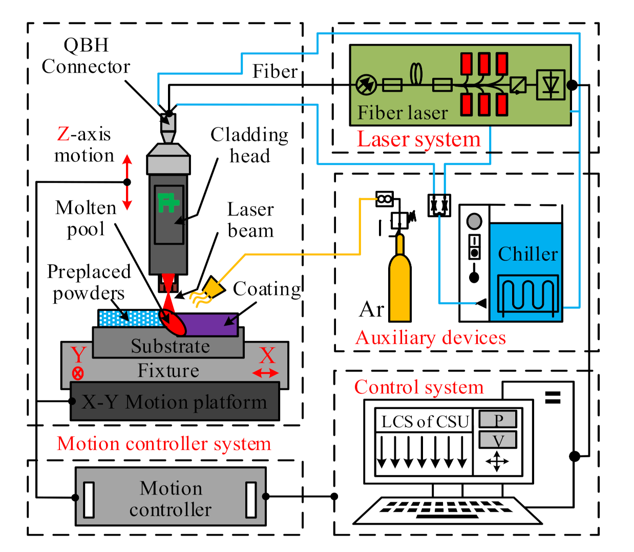
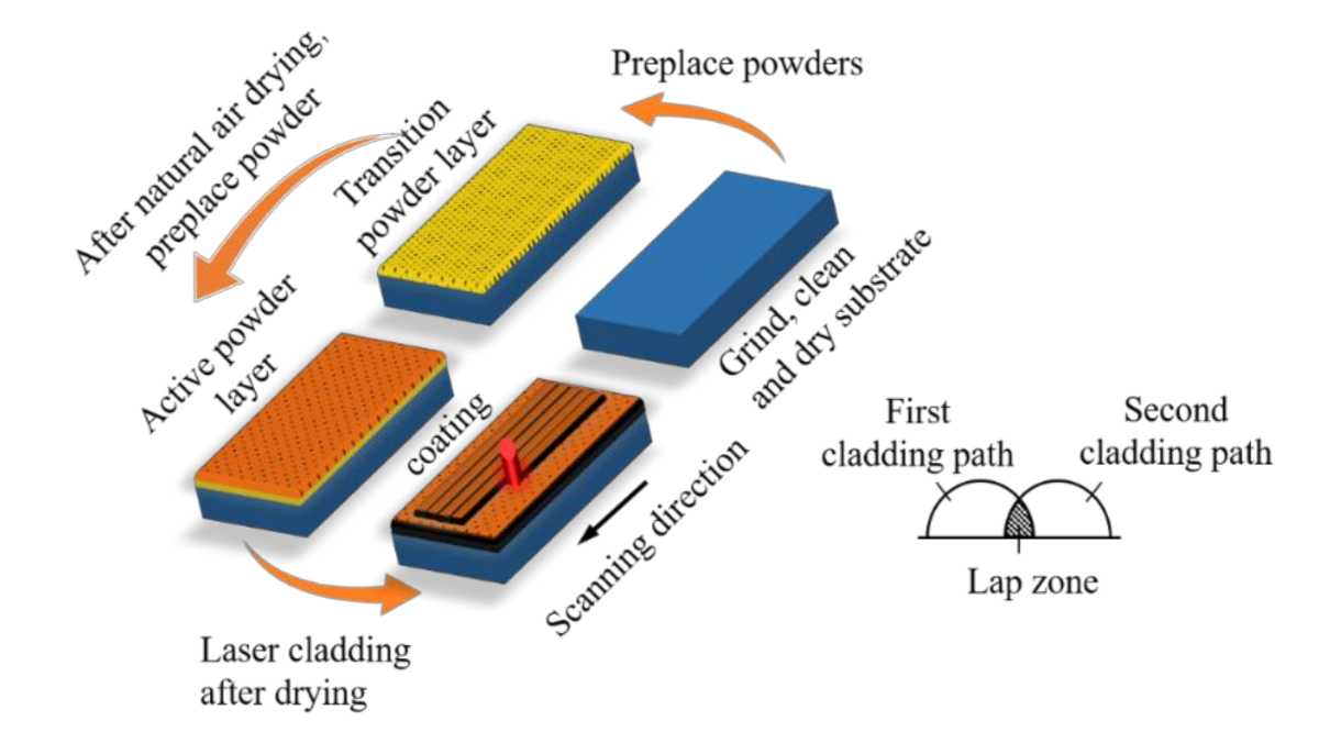
2.2. Laser-Cladding Setup and Process

The laser cladding setup adopted in this paper is shown in Figure 1. The process required a laser system, a motion-control system, a computer-control system and auxiliary devices in the laser cladding system. The most important components were the RFL-500 medium power fiber laser (Wuhan Raycus Fiber Laser Technology Co., Ltd., Wuhan, China) and the BT-230 laser head (Raytools AG, Oberburg, Switzerland), which were connected through a QBH standard connector. The motion platform and laser cladding parameters were controlled by a computer. The two-dimensional movement of the sample was achieved by the motion platform, which made it possible to produce multitrack cladding. Auxiliary devices such as an argon protection device and a water-cooling device made the process more stable.
The surfaces of the Ti alloy substrates were polished with 100#, 240# or 600# SiC polishing film to remove the oxide layer, and then cleaned using an ultrasonic cleaner in ethanol or deionized water. The process of preplacing the multilayer powder on the substrate was as follows. First, 0.1 g HT powder was mixed with the sodium silicate binder, stirred evenly, and preplaced on the surface of the substrate to form a transition powder layer. It was then left to dry naturally for 15 min. Second, 0.2 g HA powder was mixed with the sodium silicate binder and preplaced on the surface of the transition powder layer to form an active powder layer. The total thickness of the multilayer powder was about 0.8 mm. Third, the sample with the preplaced multilayer powder was placed on a heating platform (60 °C) and dried for 30 min.
The sample with the multilayer powder was placed in the laser cladding system, as shown in Figure 1, to fabricate the bioactive coating using the laser cladding process. Based on a large number of previous experimental tests, a set of optimized laser cladding process parameters was applied, as follows: laser power of 400 W, scanning speed of 3 mm/s, spot diameter of 2 mm, lap rate of 30%, and argon flow rate of 10 L/min. Figure 2 shows the laser cladding process for the preparation of the multilayer Ca/P bio-ceramic coating.

2.3. Microscopic Analysis of the Coating

2.3.1. Phase Test of the Coating

After cladding, the sample was placed in deionized water and cleaned with an ultrasonic cleaner. The surface phases of the coating were analyzed using Advance D8 X-ray diffraction (Bruker, Berne, Switzerland). X-ray scanning was performed using Cu/Kα radiation, a tube voltage of 40 kV, a tube current of 40 mA, a scanning speed of 2°/min, and a repetition accuracy of 0.001°; the test was performed in the range of 20° to 75°.

2.3.2. Microstructure Test of Coating

The sample was cut to a size of 15 mm × 6 mm × 4 mm along the direction perpendicular to the laser scanning direction. The sample section was polished and corroded with an etching agent (HF:HNO3:H2O = 2:5:93) for 15 s. A MIRA3 field emission scanning electron microscope (SEM, Tescan, Brno, Czech Republic) and an energy spectrum analyzer (EDS, Oxford Inc., Oxford, UK) were used to observe the surface morphology and test the elemental composition of the coating.

2.4. Biological Test of Coating

2.4.1. Biocompatibility Test

The biocompatibility of the ceramic coating was evaluated by a cell culture test in vitro. The cells used were MG-63 human osteosarcoma cells (Cellular Biology Institute, Shanghai, China). The medium used was a mixture of 10% fetal bovine serum (GeminiBio FoundationTM, West Sacramento, CA, USA), 1% penicillin/streptomycin (Regen Biotechnology Co. Ltd., Beijing, China) and 89% DMEM low-glucose medium (CellGro-Mediatech Inc., Manassas, VA, USA). The test was conducted in a thermostatic incubator (Thermo Fisher Scientific, Waltham, MA, USA) at a temperature of 37 °C and a carbon dioxide concentration of 5%.
In this test, the Ti6Al4V substrate was used as the control, and the test sample size was 10 mm × 10 mm × 4 mm. First, the samples were sterilized in a high temperature sterilizer (121 °C, 25 min). Then, the sterilized samples were placed into 24-well plates, and each was inoculated with 9000 cells per 1.5 mL. The constant temperature incubation periods were 1 day, 3 days, or 5 days (The culture medium was replaced every 48 h). The number of samples was six per culture cycle. The cell morphology and cell diffusion were observed using a MIRA3 TESCAN field emission scanning electron microscope. Based on the MTT cell count method, the cell proliferation of the samples was determined using a Spark 10 M enzyme linked immunoassay (TESCAN, Brno, Czech Republic).

2.4.2. Bioactivity Test

The bioactivity of the Ca/P ceramic coating was evaluated by a simulated body fluid (SBF) immersion test. Table 3 presents the recipe of the SBF solution used in the test [30].
The test sample size was 10 mm × 10 mm × 4 mm, and the Ti6Al4V substrate was also used as the control. The volume of SBF solution required for the immersion of the sample was calculated using the following Equation (8) [31]:
S/V = 0.05 cm−1
where S is the coating immersion area and V is the volume of SBF solution.
The duration of the SBF immersion tests were 6, 12, 24, and 48 h. An ICAP7400 inductively coupled plasma emission spectrometer (Thermo Fisher Scientific, Waltham, MA, USA) was used to detect the concentrations of Ca and P in the solution for each immersion period. The number of replicates for the ICAP test was three, and the average value of the three tests was considered the final value. After 48 h of immersion, the morphologies of the coating surface were observed by MIRA3 field emission scanning electron microscopy (Tescan, Brno, Czech Republic); the elemental composition of deposition zone on the coating surface was analyzed by energy dispersive spectroscopy (EDS, Oxford Inc., Oxford, UK), and the phases of the deposition zone on the coating surface were analyzed by micro-area diffraction (Rigaku Rapid IIR, Akishima City, Tokyo, Japan).

2.5. Mechanical Properties Test of the Coating

2.5.1. Microhardness Test

A HVS-1000Z automatic digital Vickers hardness tester was used to measure the microhardness of the coating section. The load was 1.96 N and the load retention time was 20 s. The hardness of different areas along the depth direction of the coating section was measured. The hardness in the same depth direction was tested three times, the average of which was taken as the final value.

2.5.2. Wear Resistance Test

A TRB3 pin-disc friction and wear tester (Anton Paar, Graz, Austria) was used to test the friction and wear properties of the coatings. The grinding pair used in the test was an Al2O3 ceramic ball (diameter: 6 mm; hardness: 1650 HV0.2). The wear resistance test parameters are listed in Table 4. At least three wear tests were performed for each test condition. The wear volume of the coating could be obtained by observing the abrasion contour with a VHX-5000 Ultra-depth microscope, and then applying Equation (9).
Vs = 2πr · A
where Vs. represents the wear volume, A is the wear area of the wear contour curve (mm2), and r is the rotation radius of the grinding ball (mm).

3. Results and Discussion

3.1. Microstructure of the Coating

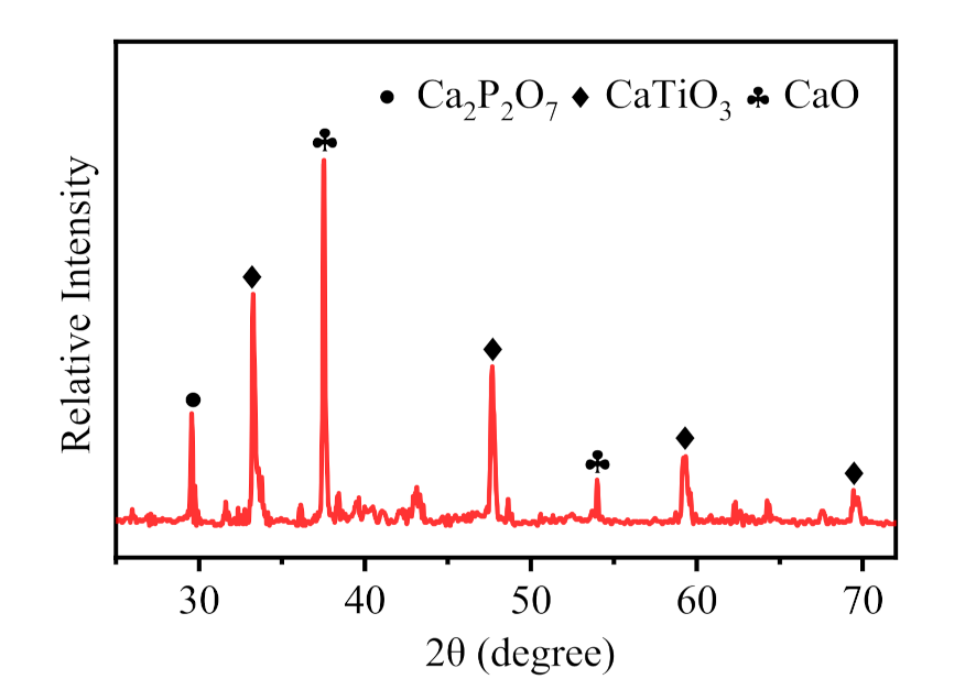
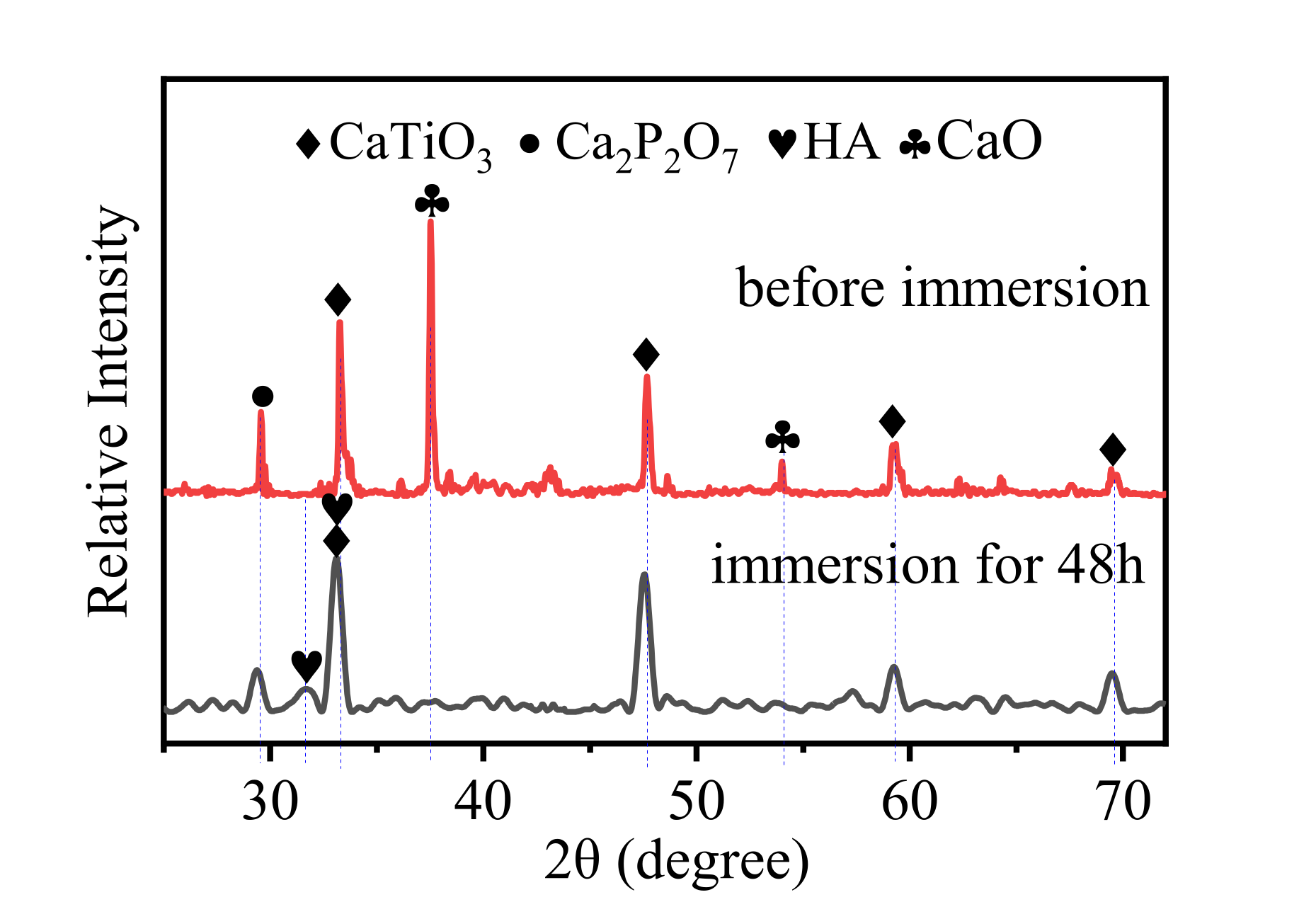
3.1.1. Phases of the Coating Surface

Figure 3 shows the X-ray diffraction pattern of the top surface of the multilayer coating fabricated by the laser cladding process. The corresponding diffraction peaks, crystal planes and phase mass fractions (RIR method) are listed in Table 5. It is seen that the coating was mainly composed of Ca2P2O7, CaO, and CaTiO3. Among these compounds, Ca2P2O7 can achieve osseous binding with bone tissue after implantation in the human body, and its binding strength is proportional to implantation time; additionally, it shows good biocompatibility and bioactivity [32]. CaO is one of the components of bioactive glass. Bioactive glass has good bioactivity, biocompatibility, and degradability, and is widely used in dentistry, orthopedics, and as a drug carrier [33]. In addition, CaTiO3 has high hardness and superior mechanical properties, and is also used as an intermediate material to improve the adhesion between bioactive substances and metals [34,35].
The formation process of new phases of CaO, Ca2P2O7, and CaTiO3 is as follows. Under irradiation via a high-energy laser beam, a molten pool is formed on the surface of the preplaced powder layer. The HA powder then begins to decompose, releasing water vapor and forming Ca3(PO4)2 and CaO. Through the process of heat conduction and convection, the HA powder in the transition layer also decomposes and melts into the molten pool, while elemental Ti in the transition layer and the titanium alloy substrate also enter the molten pool. Ti is a rather reactive element, and reacts with HA and its decomposition products, generating CaTiO3, CaO, Ca2P2O7, and other compounds. The specific reaction equations are as shown as (10)~(16) below [35,36,37].
The formation mechanism of CaO, Ca2P2O7, and CaTiO3 can be qualitatively analyzed by calculating the Gibbs free energy (ΔGθ) of the reactions listed below. According to the thermodynamic manual of inorganic materials [38], the Gibbs free energy (ΔGθ) of reactions (10)–(16) can be obtained as shown in Figure 4. The Gibbs free energies (10)–(16) are all negative after the temperature reaches 1100 K, which proves that the above reactions can occur spontaneously when the temperature reaches that point. Among them, reactions (10), (11), (15) occur most readily, all of which yield Ca3(PO4)2. It was shown that HA decomposes easily and reacts at high temperature, which is the main reason for the low HA content in the cladding coating. In addition, as one of the decomposition products of HA, Ca3(PO4)2 will continue to react with Ti to form CaTiO3 and CaO. Therefore, the final compositions of coating surface are mainly CaO, CaTiO3, Ca2P2O7.
Ca 10   ( PO 4 ) 6   ( OH ) 2   1529.1 K   3 Ca 3   ( PO 4 ) 2 + CaO + H 2 O
2Ca10 (PO4)6 (OH)2+ 5Ti → 5CaTiO3 + 5CaO + 2Ca3 (PO4)2 + 2Ca2P2O7 + H2O
2Ca3 (PO4)2 +2Ti → 2CaTiO3 + 4CaO + P4O6
2Ca2P2O7 + 2Ti → 2CaTiO3 + 2CaO + P4O6
P4O6 + 3Ti → 3TiO2 + 4P
Ca10 (PO4)6 (OH)2 + TiO2 → CaTiO3 + 3Ca3 (PO4)2 + H2O
CaO + TiO2 → CaTiO3

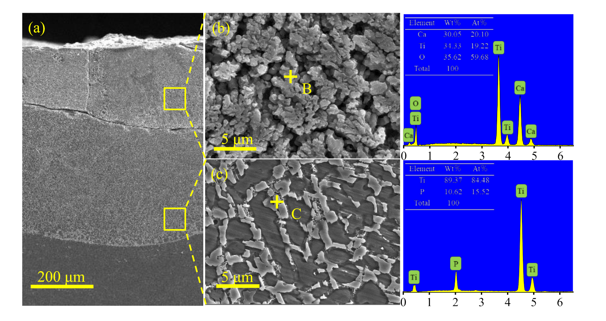
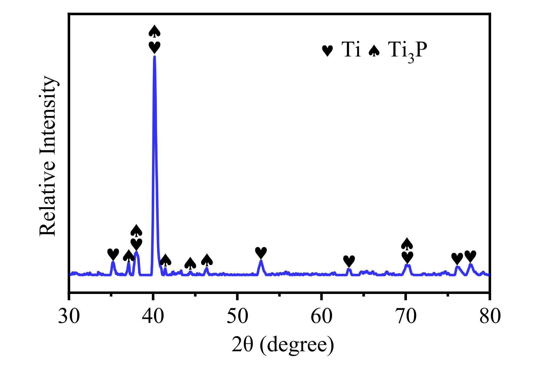
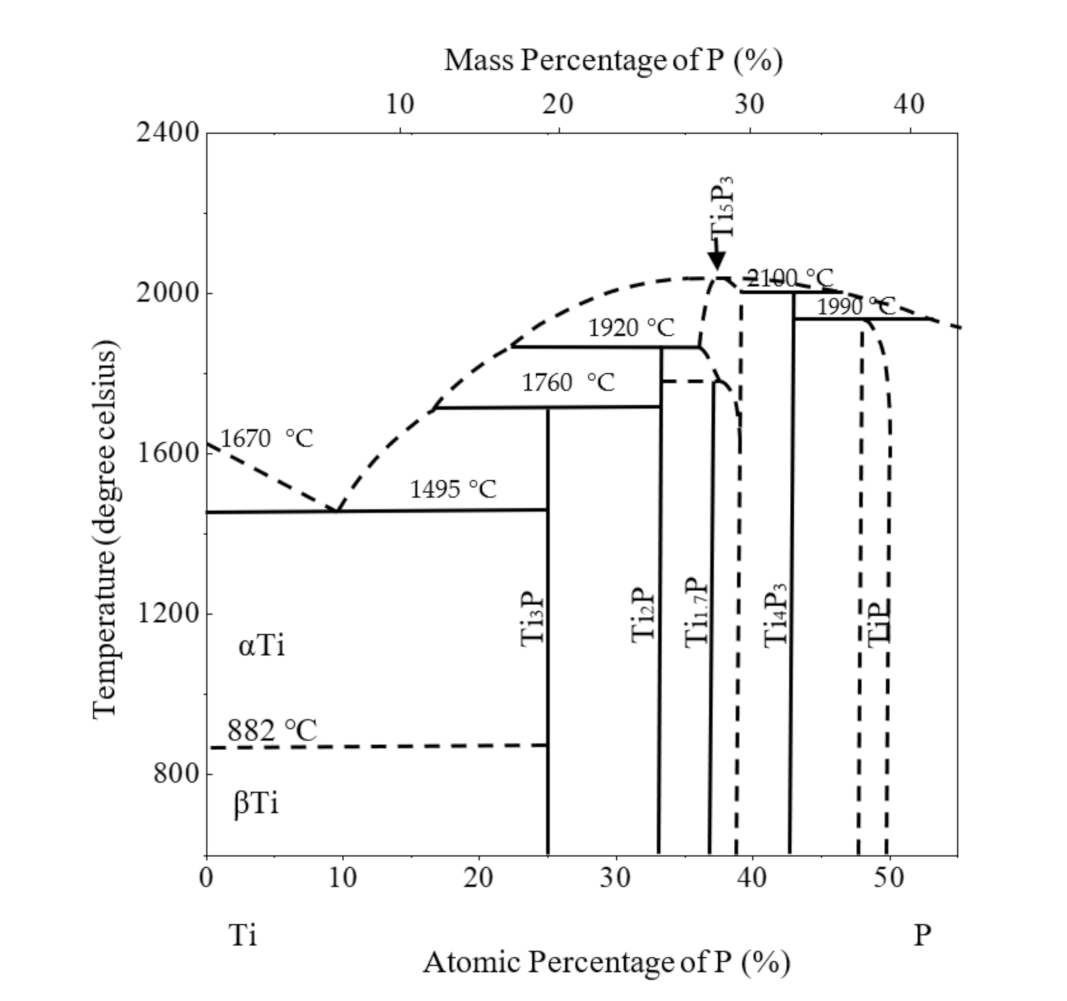
3.1.2. Phases of the Coating Section

Figure 5a shows the cross-section morphology of the Ca/P ceramic coating prepared by laser cladding. The coating consisted of two layers corresponding to the preplaced multilayer powder. Figure 5b shows the microscopic morphology of the bioactive layer (BL), which is mainly composed of dendritic granular grains. According to XRD (Figure 3) and EDS energy spectrum analyses, the phase composition of the granular grains was CaTiO3. Figure 5c shows the microscopic morphology of the transition layer (TL), which was mainly composed of rod-like grains surrounded by a Ti matrix. Figure 6 shows the X-ray diffraction pattern of the transition layer in the coating. The corresponding diffraction peaks, crystal planes and phase mass fractions (RIR method) are listed in Table 6. According to the EDS energy spectrum analysis, the rod-like grains were composed of Ti and P. According to the X-ray diffraction of the transition layer, their corresponding diffraction peaks and crystal planes, and the Ti-P binary phase diagram (as shown in Figure 7), it can be seen that the rod-like crystals were eutectoid products of Ti3P and Ti.

3.2. Biological Properties of the Coating

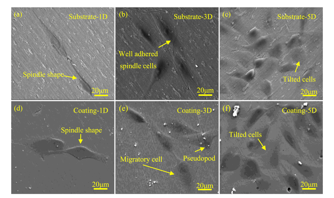
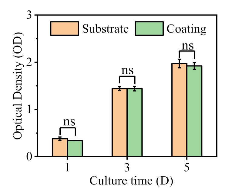
3.2.1. Biocompatibility
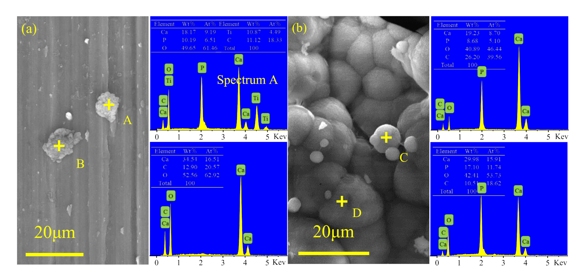
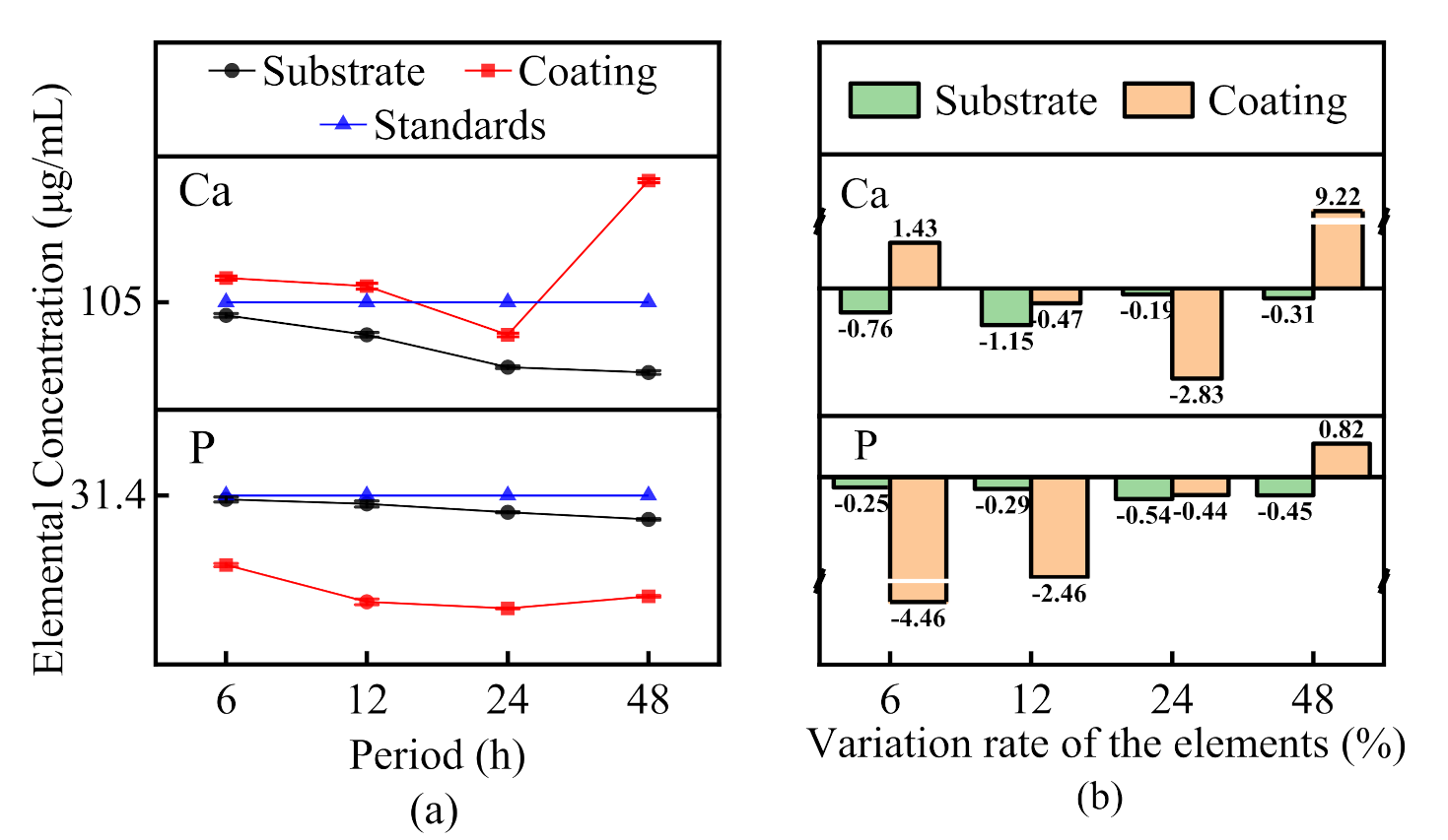
Figure 8 shows the cell morphology of MG-63 cells cultured on the substrate (control group) and the coating surface for 1 day, 3 days, and 5 days. The biocompatibility of the coatings could be evaluated by comparing the morphology and number of cells on the surface of the substrate and coating. After 1 day of culture, the cells began to spread and adhere to the surface of the substrate and coating, and showed a spindle shape. After 3 days of culture, the number of cells on the surface of both the substrate and coating increased significantly, and the cells began to appear pseudopodia, which may have promoted cell adhesion and migration [39]. After 5 days of culture, the number of cells on the substrate and coating was further increased, and the cells were tiled on the surfaces.
Figure 9 shows the quantitative statistics of the active MG-63 cells after 1, 3, and 5 days of culture on the surface of the substrate and coating. From a statistical point of view, there was no significant difference in the number of cells between the Ca/P ceramic coating surface and the substrate surface, indicating that the prepared Ca/P ceramic coating also had good biocompatibility.

3.2.2. Bioactivity

Figure 10 shows the micromorphology of the deposition on the Ti6Al4V surface (control group) and Ca/P ceramic coating surface after immersion in simulated body fluid (SBF) for 48 h. The bioactivity of the coatings was evaluated by comparing their ability to induce deposition of apatite layers in simulated body fluids. Figure 10a shows that there was only a little bit of granular deposition on the Ti alloy surface. Spectrum A shows that particle A comprised a granular deposition composed of Ca, P, O, and other elements, in which the atomic ratio of Ca to P was 1.41. Spectrum B shows that particle B was composed of Ca, C, and O, while no P was detected. Except for the deposition of a small number of particles, there was no obvious change on the Ti6Al4V surface before and after immersion. Figure 10b shows the micromorphology of the deposition layer on the surface of the Ca/P ceramic coating. The deposition layer was composed of a large number of spherical particles, which is a characteristic morphology of apatite [26,40]. Spectrum C and D show that the deposition layer was composed of Ca, P, and O, in which the atomic ratios of Ca and P were 1.7 and 1.36, respectively. To further prove the existence of apatite, the phases of the coating surface were detected before and after immersion, as shown in Figure 11. The CaO phase in the coating disappeared after immersion, and the diffraction peak intensity of Ca2P2O7 decreased. In addition, the ceramic coating surface did not have an HA phase before immersion, while the deposition layer of ceramic coating did after 48 h of immersion, indicating that the coating could induce the deposition of apatite.
Figure 12a,b show the concentration fluctuations of Ca and P in the immersion solution and the variation rate of these elements throughout the immersion period, respectively. Each point in Figure 12a is the average value of the Ca or P concentrations obtained from three ICAP tests. The average value was used to obtain the variation rates of Ca and P, as shown in Figure 12b. As shown in Figure 12a, during the immersion period of 0–12 h, the concentration of Ca in the coating immersion solution was higher than that of the SBF standard solution, while the concentration of P was lower than that of the SBF standard solution, indicating that the dissolution of the coating phase and the precipitation of solution element occurred simultaneously at this stage, and that the dissolution rate of Ca was higher than the precipitation rate. In contrast, the dissolution rate of element P was less than the precipitation rate. During the immersion period of 12–24 h, the deposition rate of the solution was higher than the dissolution rate of the coating, which was reflected by the decrease of the concentrations of Ca and P in the solution. During the immersion period of 24–48 h, the deposition rate of the solution was less than the dissolution rate of the coating, as reflected by the increase in the concentrations of Ca in the solution. There are two possible reasons for the increase of Ca ion concentration at 48 h. On the one hand, apatite deposition is a dynamic process that occurs simultaneously along with dissolution and precipitation [41]. On the other hand, in the process of apatite-induced deposition, some intermediate products are produced, including ACP amorphous apatite, ACPP amorphous calcium pyrophosphate, etc. These intermediate products are precursors of HA, which may release Ca ions during the process of conversion to HA. The hydrolytic conversion of amorphous calcium phosphate into apatite accompanied the sustained release of calcium and orthophosphate ions [42,43]. However, during the immersion period of the Ti6Al4V alloy, the concentrations of Ca and P in the solution continued to decrease slowly, and the Ti6Al4V alloy did not show any ion exchange with the SBF solution.
Figure 12b shows the variation rates DC and DP of Ca and P ions in the solution during the immersion process of the Ti6Al4V substrate and coating:
DPn = Pn+1 − Pn/Pn
DCn = Cn+1 − Cn/Cn
where DPn is the variation rate of the concentration of P ions in the period from tn to tn+1, and DCn is the variation rate of the concentration of Ca ions in the period from tn to tn+1. Time t1, t2, t3 and t4 correspond to 6 h, 12 h, 24 h and 48 h, respectively. It can be seen from Figure 12b that ion exchange occurred between the coating and SBF solution during the immersion period, while the Ti6Al4V alloy did not show ion exchange with the SBF solution. In addition, the variation rates of the Ca and P concentrations in the coating immersion solution were much higher than in the Ti6Al4V alloy immersion solution, that is, the deposition rate of elements in the coating immersion solution was higher than in the Ti6Al4V alloy immersion solution. This is consistent with the SEM observation that less deposition had occurred on the surface of the Ti6Al4V alloy, while significant apatite deposition had occurred the coating surface.
Therefore, according to the ICAP, SEM, and XRD test results, it can be concluded that the Ca/P ceramic coating has the ability to induce hydroxyapatite, and has good bioactivity, while the titanium alloy substrate has no biological activity. This is attributed to the fact that only one deposition mode occurred during the immersion period of the titanium alloy, i.e., component nucleation, while two deposition modes occurred during the immersion period of the coating, i.e., component nucleation and structure nucleation.
During the immersion process of the titanium alloy, due to the molecular movement of saturated Ca2+ and PO 4 3 in SBF solution, the solution locally reached the nucleation site of the components, and then the component nucleation deposits; however, the deposition was slow, so there was far less deposition on the surface of titanium alloy. However, during the immersion process of the coating, active substances CaO and Ca2P2O7 formed nucleation sites containing -OH on the surface of the coating through hydrolysis, promoting the adsorption of Ca2+ and PO 4 3 in succession, and inducing the nucleation and growth of apatite, that is, structural nucleation deposition. At the same time, the Ca2+, PO 4 3 , and OH dissolved in the coating reached a supersaturated state in the solution, accelerating the movement of molecules and allowing the solution to more rapidly reach the nucleation sites of the components, so that apatite component nucleated out, as shown in Figure 13. Thus, after immersion for 48 h, an apatite deposition layer formed on the surface of the coating. The dissolution and precipitation equations are as follows [40,44,45]:
CaO + H2O → Ca2+ + OH
Ca2P2O7 + H2O → Ca2+ + PO43
OH + Ca2+ + PO43− → Ca10(PO4)6(OH)2

3.3. Mechanical Properties of the Coating

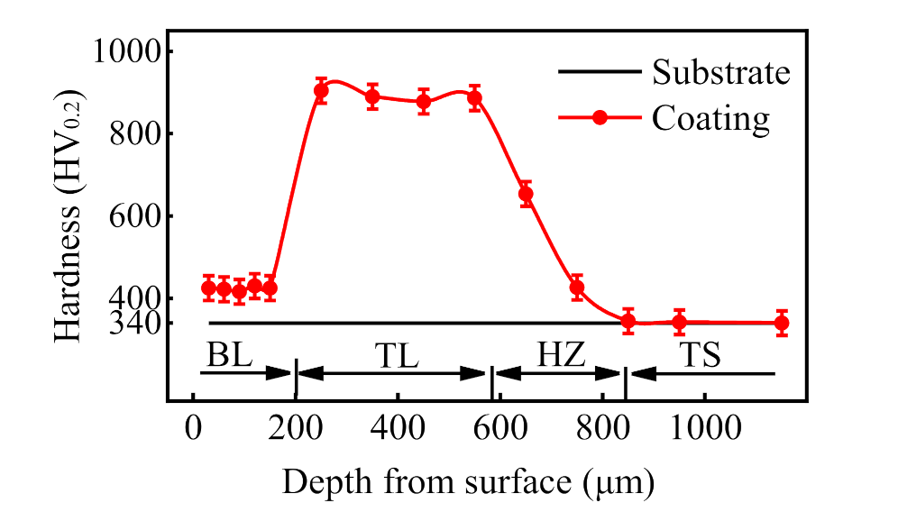
3.3.1. Microhardness

Figure 14 shows the microhardness distribution of a ceramic coating section in the direction of depth. In the direction of depth, the sample can be divided into three regions: a coating zone (BL, TL), heat affected zone (HZ) and substrate zone (TS). In the coating area, the bioactive layer (BL) thickness was about 0.2 mm, the average microhardness was 440 HV0.2, the transition layer (TL) thickness was about 0.4 mm, and the average microhardness is 889.75 HV0.2. The thickness of the heat-affected zone with an average microhardness of 655.67 HV0.2 was about 0.3 mm, and the microhardness showed a decreasing trend within this range. The average microhardness of the substrate is 340 HV0.2. The results show that, compared with the substrate, the microhardness of the bioactive layer and the transition layer had increased by 24.1% and 161.7%, respectively. This was due to the formation of the hard phase CaTiO3 in the bioactive layer and the eutectoid products Ti3P and Ti in the transition layer. This indicates that the coating not only ensured good biocompatibility and bioactivity, but also achieved a significant improvement in hardness compared with the Ti6Al4V substrate and the related coatings, as reported by Bajda et al. [9] and Pei.

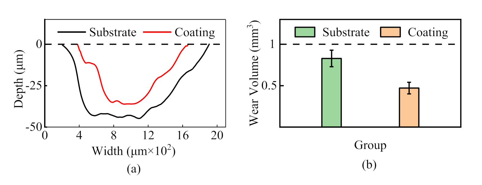
3.3.2. Wear Resistance

The wear contour curves of the Ti6Al4V alloy (control group) and coating are shown in Figure 15a, and the wear volumes taken from three repeated tests are shown in Figure 15b. The friction and wear properties of the coating can be evaluated by analyzing the wear contour and volume of both the coating and Ti6Al4V alloy. The average wear-section width and depth of the Ti6Al4V alloy were 1570 μm and 44 μm, respectively, and that of the coating were 1190 μm and 35 μm, respectively. The wear volume of the Ti6Al4V alloy was 0.829 mm3, while that of the coating was 0.471mm3. The variation of the wear volume conformed to the Holm-Archard wear law [46], that is, wear volume is inversely proportional to hardness. The results showed that the wear volume of the ceramic coating was reduced by 43.2% relative to the Ti6Al4V alloy, and therefore, that the ceramic coating had better wear resistance.

4. Conclusions

A multilayer Ca/P bioactive ceramic coating was prepared on the surface of a Ti6Al4V alloy by the application of a laser cladding technique. The biocompatibility and bioactivity of the coating were evaluated by in vitro cell culture and simulated body fluid immersion tests, respectively. The wear resistance of the Ca/P ceramic coating was evaluated by microhardness and wear tests. The main conclusions are as follows:
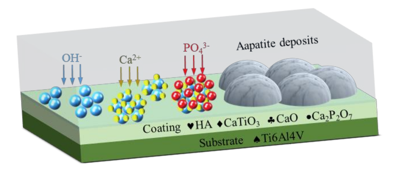
  • The multilayer Ca/P bio-ceramic coating was mainly composed of CaO, CaTiO3, Ca2P2O7, Ti3P, and other phases.
  • The multilayer Ca/P bio-ceramic coating exhibited biocompatibility equal to that of Ti6Al4V alloy, which is widely used in the field of medical implants.
  • The multilayer Ca/P bio-ceramic coating had good bioactivity in vitro, and could induce and deposit hydroxyapatite on its surface when immersed in SBF solution. Specifically, the coating showed obvious ion exchange during the immersion period, whereas the titanium alloy substrate did not.
  • The multilayer Ca/P bio-ceramic coating showed better microhardness and wear resistance than the Ti alloy substrate. Compared with the substrate (340HV0.2), the microhardness of the bioactive layer (440HV0.2) and the transition layer (889.75 HV0.2) increased by 24.1% and 161.7%, respectively. Additionally, the wear volume of the coating was 0.471 mm3, i.e., 43.2% less than that of Ti6Al4V alloy (0.829 mm3).

Author Contributions

Conceptualization, B.L. and D.L.; investigation, B.L. and Z.D.; resources, B.L.; data curation, Z.D. and D.L.; writing—original draft preparation, B.L.; writing—review and editing, D.L.; visualization, B.L. and Z.D.; supervision, D.L.; project administration, D.L.; funding acquisition, D.L. All authors have read and agreed to the published version of the manuscript.

Funding

This research was funded by (1) National Natural Science Foundation of China, Grant No. 51775559; (2) The Project of State Key Laboratory of High Performance Complex Manufacturing, Grant No. ZZYJKT2019-06, (3) The Natural Science Foundation of Hunan province of China, Grant No. 2020JJ4716.

Institutional Review Board Statement

Not applicable.

Informed Consent Statement

Not applicable.

Data Availability Statement

Data is concerned within the article.

Conflicts of Interest

The authors declare no conflict of interest.

References

  1. Luo, Y.; Yang, L.; Tian, M. Application of Biomedical-Grade Titanium Alloys in Trabecular Bone and Artificial Joints; John Wiley & Sons: Hoboken, NJ, USA, 2013; pp. 181–216. [Google Scholar]
  2. Avila, J.; Bose, S.; Bandyopadhyay, A. Additive manufacturing of titanium and titanium alloys for biomedical applications. In Titanium in Medical and Dental Applications; Elsevier: Amsterdam, The Netherlands, 2018; pp. 325–343. [Google Scholar]
  3. Alipal, J.; Pu’Ad, N.M.; Nayan, N.; Sahari, N.; Abdullah, H.; Idris, M.; Lee, T. An updated review on surface functionalisation of titanium and its alloys for implants applications. Mater. Today Proc. 2021, 42, 270–282. [Google Scholar] [CrossRef]
  4. Gallo, J.; Goodman, S.; Konttinen, Y.; Wimmer, M.; Holinka, M. Osteolysis around total knee arthroplasty: A review of pathogenetic mechanisms. Acta Biomater. 2013, 9, 8046–8058. [Google Scholar] [CrossRef] [Green Version]
  5. Hinman, A.D.; Prentice, H.A.; Paxton, E.W.; Kelly, M.P. Modular tibial stem use and risk of revision for aseptic loosening in cemented primary total knee arthroplasty. J. Arthroplast. 2021, 36, 1577–1583. [Google Scholar] [CrossRef]
  6. Koks, S.; Wood, D.J.; Reimann, E.; Awiszus, F.; Lohmann, C.H.; Bertrand, J.; Prans, E.; Maasalu, K.; Martson, A. The genetic variations associated with time to aseptic loosening after total joint arthroplasty. J. Arthroplast. 2020, 35, 981–988. [Google Scholar] [CrossRef]
  7. Wiliams, D.F. Biomechanical considerations in the loosening of hip replacement prosthesis. In Current Perspectives on Implantable Devices; JAI Press Inc.: Stamford, CT, USA, 1989; pp. 1–45. [Google Scholar]
  8. Geetha, M. Ti based biomaterials, the ultimate choice for orthopaedic implants—A review. Prog. Mater. Sci. 2009, 54, 397–425. [Google Scholar] [CrossRef]
  9. Bajda, S.; Liu, Y.; Tosi, R.; Cholewa-Kowalska, K.; Krzyzanowski, M.; Dziadek, M.; Kopyscianski, M.; Dymek, S.; Polyakov, A.V.; Semenova, I.P.; et al. Laser cladding of bioactive glass coating on pure titanium substrate with highly refined grain structure. J. Mech. Behav. Biomed. Mater. 2021, 119, 104519. [Google Scholar] [CrossRef] [PubMed]
  10. Mansoor, P.; Dasharath, S. Synthesis and characterization of wollastonite (CaSiO3)/titanium oxide (TiO2) and hydroxyapatite (HA) ceramic composites for bio-medical applications fabricated by spark plasma sintering technology. Mater. Today Proc. 2021, 45, 332–337. [Google Scholar] [CrossRef]
  11. Roy, M.; Krishna, B.V.; Bandyopadhyay, A.; Bose, S. Laser processing of bioactive tricalcium phosphate coating on titanium for load-bearing implants. Acta Biomater. 2008, 4, 324–333. [Google Scholar] [CrossRef]
  12. Zhou, X.; Siman, R.; Lu, L.; Mohanty, P. Argon atmospheric plasma sprayed hydroxyapatite/Ti composite coating for biomedical applications. Surf. Coat. Technol. 2012, 207, 343–349. [Google Scholar] [CrossRef]
  13. Liu, D.; Savino, K.; Yates, M.Z. Coating of hydroxyapatite films on metal substrates by seeded hydrothermal deposition. Surf. Coat. Technol. 2011, 205, 3975–3986. [Google Scholar] [CrossRef]
  14. Chakraborty, R.; Seesala, V.; Sengupta, S.; Dhara, S.; Saha, P.; Das, K.; Das, S. Comparison of osteoconduction, cytocompatibility and corrosion protection performance of hydroxyapatite-calcium hydrogen phosphate composite coating synthesized in-situ through pulsed electro-deposition with varying amount of phase and crystallinity. Surf. Interfaces 2018, 10, 1–10. [Google Scholar] [CrossRef]
  15. Tlotleng, M.; Akinlabi, E.; Shukla, M.; Pityana, S. Microstructures, hardness and bioactivity of hydroxyapatite coatings deposited by direct laser melting process. Mater. Sci. Eng. C 2014, 43, 189–198. [Google Scholar] [CrossRef] [PubMed]
  16. Greish, Y.E.; Al Shamsi, A.S.; Polychronopoulou, K.; Ayesh, A. Structural evaluation, preliminary in vitro stability and electrochemical behavior of apatite coatings on Ti6Al4V substrates. Ceram. Int. 2016, 42, 18204–18214. [Google Scholar] [CrossRef]
  17. Ji, X.; Zhao, M.; Dong, L.; Han, X.; Li, D. Influence of Ag/Ca ratio on the osteoblast growth and antibacterial activity of TiN coatings on Ti-6Al-4V by Ag and Ca ion implantation. Surf. Coat. Technol. 2020, 403, 126415. [Google Scholar] [CrossRef]
  18. Wang, D.; Chen, C.; Yang, X.; Ming, X.; Zhang, W. Effect of bioglass addition on the properties of HA/BG composite films fabricated by pulsed laser deposition. Ceram. Int. 2018, 44, 14528–14533. [Google Scholar] [CrossRef]
  19. Azari, R.; Rezaie, H.R.; Khavandi, A. Investigation of functionally graded HA-TiO2 coating on Ti–6Al–4V substrate fabricated by sol-gel method. Ceram. Int. 2019, 45, 17545–17555. [Google Scholar] [CrossRef]
  20. Lenis, J.A. Structure, morphology, adhesion and in vitro biological evaluation of antibacterial multi-layer HA-Ag/SiO2/TiN/Ti coatings obtained by RF magnetron sputtering for biomedical applications. Mater. Sci. Eng. C 2020, 116, 111268. [Google Scholar] [CrossRef] [PubMed]
  21. Bansal, P.; Singh, G.; Sidhu, H.S. Improvement of surface properties and corrosion resistance of Ti13Nb13Zr titanium alloy by plasma-sprayed HA/ZnO coatings for biomedical applications. Mater. Chem. Phys. 2021, 257, 123738. [Google Scholar] [CrossRef]
  22. Zhu, L.; Xue, P.; Lan, Q.; Meng, G.; Ren, Y.; Yang, Z.; Xu, P.; Liu, Z. Recent research and development status of laser cladding: A review. Opt. Laser Technol. 2021, 138, 106915. [Google Scholar] [CrossRef]
  23. Li, H.C. Effect of Na2O and ZnO on the microstructure and properties of laser cladding derived CaO-SiO2 ceramic coatings on titanium alloys. J Colloid Interface Sci. 2021, 592, 498–508. [Google Scholar] [CrossRef] [PubMed]
  24. Behera, R.R.; Hasan, A.; Sankar, M.R.; Pandey, L.M. Laser cladding with HA and functionally graded TiO2-HA precursors on Ti–6Al–4V alloy for enhancing bioactivity and cyto-compatibility. Surf. Coat. Technol. 2018, 352, 420–436. [Google Scholar] [CrossRef]
  25. Zhang, S.; Liu, Q.; Li, L.; Bai, Y.; Yang, B. The controllable lanthanum ion release from Ca-P coating fabricated by laser cladding and its effect on osteoclast precursors. Mater. Sci. Eng. C 2018, 93, 1027–1035. [Google Scholar] [CrossRef]
  26. Yang, Y. Osteoblast interaction with laser cladded HA and SiO2-HA coatings on Ti–6Al–4V. Mater. Sci. Eng. C 2011, 31, 1643–1652. [Google Scholar] [CrossRef]
  27. Pei, X.; Wang, J.; Wan, Q.; Kang, L.; Xiao, M.; Bao, H. Functionally graded carbon nanotubes/hydroxyapatite composite coating by laser cladding. Surf. Coat. Technol. 2011, 205, 4380–4387. [Google Scholar] [CrossRef]
  28. Tsui, Y.; Doyle, C.; Clyne, T. Plasma sprayed hydroxyapatite coatings on titanium substrates Part 1: Mechanical properties and residual stress levels. Biomaterials 1998, 19, 2015–2029. [Google Scholar] [CrossRef]
  29. Vasquez, F.A.; Ramos-Grez, J.A.; Walczak, M. Multiphysics simulation of laser–material interaction during laser powder depositon. Int. J. Adv. Manuf. Technol. 2011, 59, 1037–1045. [Google Scholar] [CrossRef]
  30. Oyane, K. Preparation and assessment of revised simulated body fluids. J. Biomed. Mater. Res. Part A 2003, 65, 188–195. [Google Scholar] [CrossRef]
  31. Müller, L.; Müller, F.A. Preparation of SBF with different HCO3 content and its influence on the composition of biomimetic apatites. Acta Biomater. 2006, 2, 181–189. [Google Scholar] [CrossRef]
  32. Kasuga, T. Bioactive calcium pyrophosphate glasses and glass-ceramics. Acta Biomater. 2005, 1, 55–64. [Google Scholar] [CrossRef]
  33. Henao, J.; Poblano-Salas, C.; Monsalve, M.; Corona-Castuera, J.; Barceinas-Sanchez, O. Bio-active glass coatings manufactured by thermal spray: A status report. J. Mater. Res. Technol. 2019, 8, 4965–4984. [Google Scholar] [CrossRef]
  34. Chen, C.-Y.; Ozasa, K.; Katsumata, K.-I.; Maeda, M.; Okada, K.; Matsushita, N. CaTiO3 nanobricks prepared from anodized TiO2 nanotubes. Electrochem. Commun. 2012, 22, 101–104. [Google Scholar] [CrossRef]
  35. Yadi, M.; Esfahani, H.; Sheikhi, M.; Mohammadi, M. CaTiO3/α-TCP coatings on CP-Ti prepared via electrospinning and pulsed laser treatment for in-vitro bone tissue engineering. Surf. Coat. Technol. 2020, 401, 126256. [Google Scholar] [CrossRef]
  36. Roy, M.; Balla, V.; Bandyopadhyay, A.; Bose, S. Compositionally graded hydroxyapatite/tricalcium phosphate coating on Ti by laser and induction plasma. Acta Biomater. 2011, 7, 866–873. [Google Scholar] [CrossRef] [PubMed]
  37. Lusquiños, F.; De Carlos, A.; Pou, J.; Arias, J.L.; Boutinguiza, M.; León, B.; Pérez-Amor, M.; Driessens, F.C.M.; Hing, K.; Gibson, I.; et al. Calcium phosphate coatings obtained by Nd: YAG laser cladding: Physicochemical and biologic properties. J. Biomed. Mater. Res. Part A 2003, 64, 630–637. [Google Scholar] [CrossRef]
  38. Ye, D. Manual of Practical Inorganic Thermodynamics Data; Metallurgical Industry Press: Beijing, China, 2002. [Google Scholar]
  39. Xie, K.; Yang, Y.; Jiang, H. Controlling cellular volume via mechanical and physical properties of substrate. Biophys. J. 2018, 114, 675–687. [Google Scholar] [CrossRef] [PubMed] [Green Version]
  40. Paital, S.R.; Dahotre, N.B. Wettability and kinetics of hydroxyapatite precipitation on a laser-textured Ca-P bioceramic coating. Acta Biomater. 2009, 5, 2763–2772. [Google Scholar] [CrossRef]
  41. Lu, X.; Leng, Y. Theoretical analysis of calcium phosphate precipitation in simulated body fluid. Biomaterials 2005, 26, 1097–1108. [Google Scholar] [CrossRef] [PubMed]
  42. Dridi, A.; Riahi, K.Z.; Somrani, S. Mechanism of apatite formation on a poorly crystallized calcium phosphate in a simulated body fluid (SBF) at 37 °C. J. Phys. Chem. Solids 2021, 156, 110122. [Google Scholar] [CrossRef]
  43. Edén, M. Structure and formation of amorphous calcium phosphate and its role as surface layer of nanocrystalline apatite: Implications for bone mineralization. Materialia 2021, 17, 101107. [Google Scholar] [CrossRef]
  44. Bakher, Z. Solubility study at high phosphorus pentoxide concentration in ternary system CaCO3 + P2O5 + H2O at 25, 35 and 70 °C. Fluid Phase Equilib. 2018, 478, 90–99. [Google Scholar] [CrossRef]
  45. Bakhsheshi-Rad, H.; Hamzah, E.; Ismail, A.F.; Kasiri-Asgarani, M.; Daroonparvar, M.; Parham, S.; Iqbal, N.; Medraj, M. Novel bi-layered nanostructured SiO2/Ag-FHAp coating on biodegradable magnesium alloy for biomedical applications. Ceram. Int. 2016, 42, 11941–11950. [Google Scholar] [CrossRef]
  46. Yamamoto, S. Physical meaning of the wear volume equation for nitrogenated diamond-like carbon based on energy considerations. Wear 2016, 368–369, 156–161. [Google Scholar] [CrossRef]
Figure 1. Schematic diagram of laser cladding set-up.
Coatings 11 00891 g001
Figure 2. Flow diagram of the laser cladding process.
Coatings 11 00891 g002
Figure 3. X-ray diffraction pattern of Ca/P ceramic coating top surface.
Coatings 11 00891 g003
Figure 4. Gibbs free energy of Equations (10)–(16).
Coatings 11 00891 g004
Figure 5. (a) Microstructure morphology of Ca/P ceramic coating section (b) bioactive layer (c) transition layer.
Coatings 11 00891 g005
Figure 6. X-ray diffraction pattern of the phase of the transition layer.
Coatings 11 00891 g006
Figure 7. Ti-P binary phase diagram.
Coatings 11 00891 g007
Figure 8. Morphology of MG-63 cells cultured on substrate (ac) and coating (df) after 1, 3 and 5 days.
Coatings 11 00891 g008
Figure 9. Quantitative statistics of active MG-63 cells after 1, 3, and 5 days of culture on the surface of the substrate and coating (ns stands for no significant difference).
Coatings 11 00891 g009
Figure 10. Micromorphology of surface deposits of substrate (a) and Ca/P ceramic coating (b) after 48 h of immersion in SBF solution.
Coatings 11 00891 g010
Figure 11. X-ray diffraction pattern of Ca/P ceramic coating before and after SBF immersion.
Coatings 11 00891 g011
Figure 12. Concentrations of Ca and P in the immersion solution (a), the variation rate of the elements (b) during the immersion period of the coating and Ti6Al4V alloy.
Coatings 11 00891 g012
Figure 13. Schematic diagram of coating induced deposition of apatite.
Coatings 11 00891 g013
Figure 14. Microhardness distribution diagram of coating section along depth direction.
Coatings 11 00891 g014
Figure 15. The wear contour curves (a) and wear volume (b) of Ti6Al4V alloy and coating.
Coatings 11 00891 g015
Table 1. Table of preplaced multilayer powder.
LayerMass Fraction/wt%Weight/g
HATi
The Transition Powder Layer50500.1
The Active Powder Layer10000.2
Table 2. Thermo-physical parameters of Ti6Al4V, Ti, HA, and HT at room temperature.
MaterialLinear Thermal Expansion Coefficient
1/°C
Melting Point
°C
Specific Heat Capacity
J/(kg·°C)
Density
kg/m−3
Ti6Al4V9.41 × 10−61646 ± 425204430
Ti8.8 × 10−616885284500
HA13.3 × 10−619237663156
HT11.446 × 10−619236473828
Table 3. Preparation reagent and dosage of SBF per liter.
OrderReagentDosage/g
1NaCl8.035
2NaHCO30.355
3KCl0.225
4 aK2HPO40.231
5MgCl2·6H2O0.311
61.0 mol/L HCl39 mL
7CaCl20.292
8Na2SO40.072
9Tris6.118
10 b1.0 mol/L HCl0–5 mL
a K2HPO4 alternatives K2HPO4·3H2O. b HCl acts as a pH regulator to maintain a solution pH of 7.40.
Table 4. Experimental parameters of the wear test.
ParameterValueUnit
Load5N
Temperature36.5 ± 1°C
Wear time30mins
Rotation radius3mm
Rotation speed400r/min
Table 5. The phases of the coating surface and their corresponding diffraction peaks, crystal planes, and phase mass fractions (RIR method).
PhasePdf CardDiffraction Peaks/PlaneMass Fraction (%)
Ca2P2O709-034629.5°/[0 0 8]7.5
CaO82-169137.4°/[2 0 0]64.2°/[3 1 1]65.6
54.0°/[2 2 0]67.4°/[2 2 2 ]
CaTiO365-328733.3°/[1 1 0]59.5°/[2 1 1]26.9
47.8°/[2 0 0]69.9°/[2 2 0]
Table 6. The phases of the transition layer in the coating and their corresponding diffraction peaks, crystal planes, and phase mass fractions (RIR method).
PhasePdf CardDiffraction Peaks/PlaneMass Fraction(%)
Ti89-500935.1°/[1 0 0]63.1°/[1 1 0]50.6
38.4°/[0 0 2]70.7°/[1 0 3]
40.2°/[1 0 1]76.3°/[1 1 2]
53.0°/[1 0 2]77.5°/[2 0 1]
Ti3P89-241637.1°/[3 2 1]
38.2°/[1 1 2]
40.4°/[4 0 1]
41.5°/[1 4 1]
44.4°/[2 2 2]
46.4°/[3 1 2]
70°6/[2 6 2]
49.4
Publisher’s Note: MDPI stays neutral with regard to jurisdictional claims in published maps and institutional affiliations.

