Application of Adaptive Materials and Coatings to Increase Cutting Tool Performance: Efficiency in the Case of Composite Powder High Speed Steel

 ,
,  ,
,  , ,
, , 
Abstract
:1. Introduction
- Diamond-like carbon coatings;
- Metal nitrides (TiN, CrN);
- Transition metal and dichalgogenide materials (MoS2, WS2);
- Polymers;
- Soft metals of the copper subgroup (with a filled pre-external (n − 1)d-sublevel—3d104s1, 4d105s1, 4f145d106s1 such as silver, copper, gold).
- extremely high level of contact pressures on the tool working surfaces, often exceeding 100 MPa;
- the temperature on the friction surfaces during cutting reaches 600 °C and above;
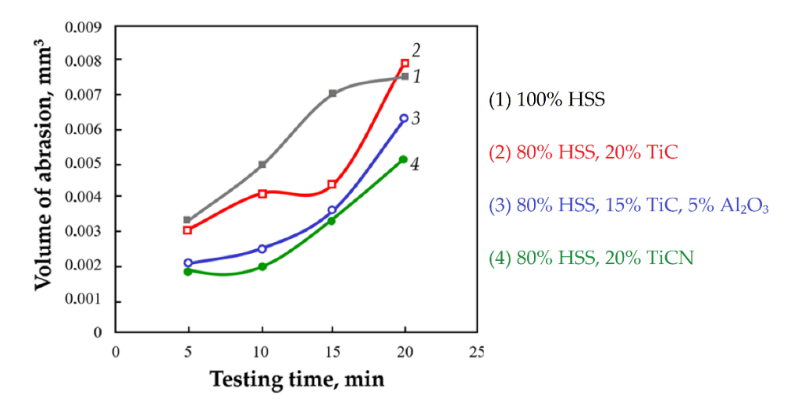
- 100% HSS (HS6-5-2C steel powder);
- CPHSS samples of 80% HSS, 20% TiC (option 1);
- CPHSS samples of 80% HSS, 15% TiC, 5% Al2O3 (option 2);
- CPHSS samples of 80% HSS, 20% TiCN (option 3).
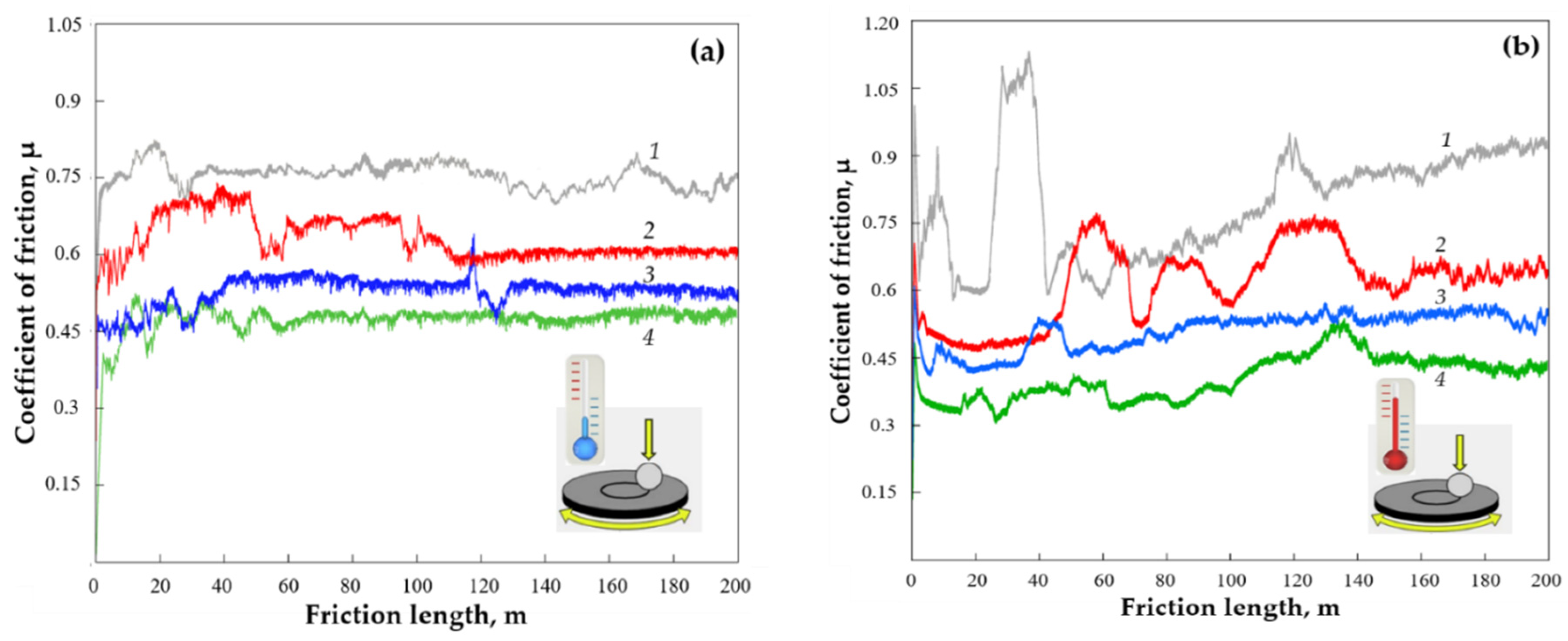
- The coefficient of friction did not exceed 0.45 for 80% HSS + 20%TiCN at +20 °C and 600 °C);
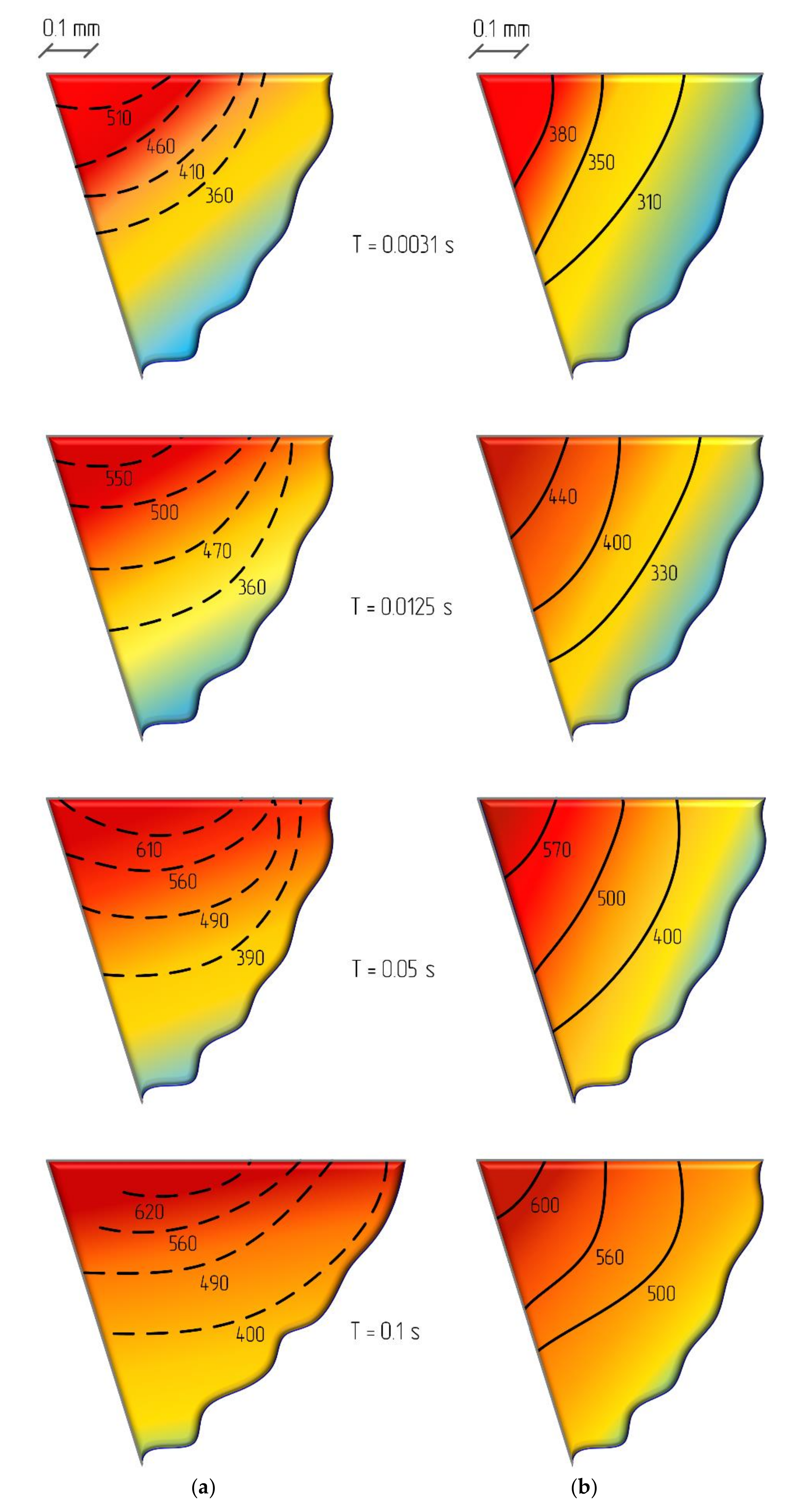
- A graphical visualization of temperature fields in the tool cutting wedge section showed development of the maximum temperature from the tip to the flank face over time for HSS material. The zone of maximum temperatures remains at the top of the cutting wedge for CPHSS material. The temperature rise at the very beginning of the working stroke is less intense, and the level of fields is reduced by 20%–25%.
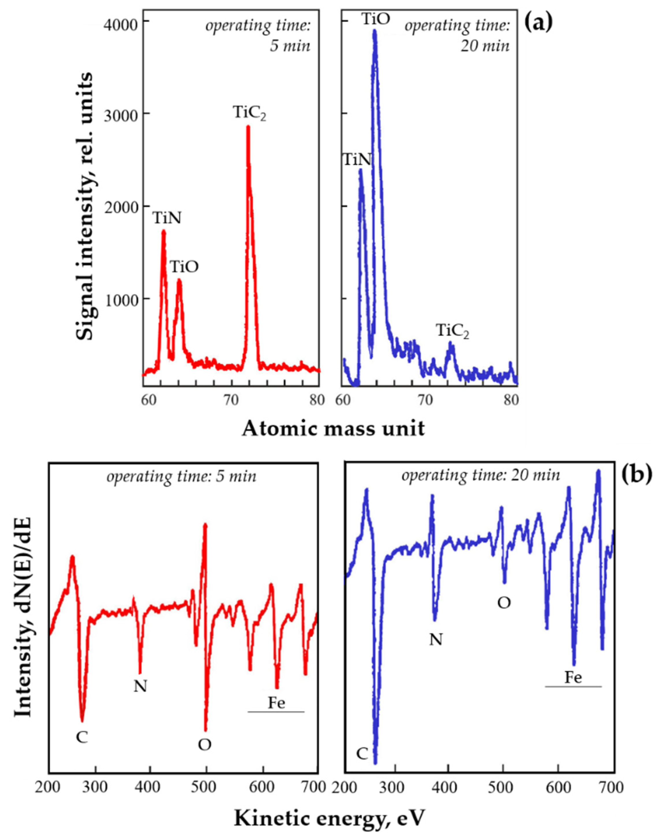
- Spectral analysis shows the highest spectrum intensity of TiC2 after 5 min of running in. After 20 min of milling (V = 82 m/min, f = 0.15 mm/tooth, B = 5 mm, and t = 0.5 mm), dicarbide decomposes and transits to thermally stable secondary phase films of good lubricity such as TiO (maximum spectrum intensity) and TiN (partially);
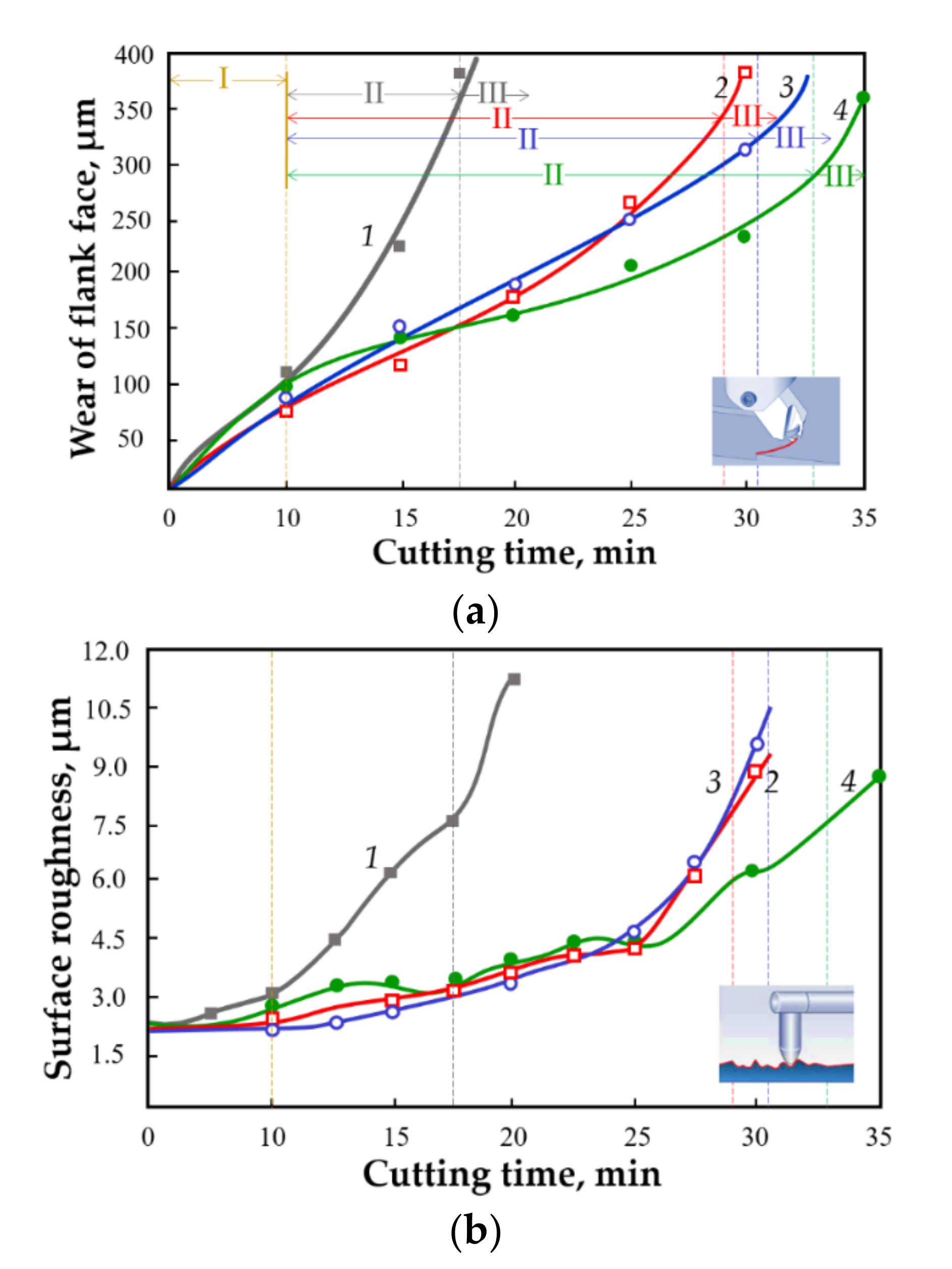
- There was an increase in tool life of up to 2 times (>35 min for 80% HSS + 20% TiCN);
- There was a decrease in the roughness of up to 2.9 times (Ra less than 4.5 µm after 25 min of milling).
1.1. Cutting Tool Performance and AMC Challenges
- reducing the possibility of the development of creep and dynamic recrystallization processes, which weaken the cutting edge at the flank face and lead to catastrophic wear (typical for high speed steels);
- a decrease in the intensity of crater formation on the rake face, which reduces the strength of the cutting edge and leads to its destruction and rapid catastrophic wear of the cutting part of the tool;
- a decrease in the intensity of abrasive and adhesive wear on the tool flank, leading to an increase in temperature and catastrophic wear;
- reducing the possibility of plastic deformation of the cutting part of the tool (lowering or indentation), which worsens the removal of chips from the cutting zone, and reduces the workpiece dimensional accuracy and surface quality;
- prevention of the formation of or obstacle to the development of thermal microcrack networks on the tool cutting edge, which increases the risk of the cutting part chipping and reduces the tool resource;
- a decrease in the intensity of build-up on the rake face, which reduces the dimensional accuracy of the part and the quality of the surface (periodic detachment of the build-up leads to the formation of cracks near the cutting edge, reducing the tool life);
- minimization of the possibility of tool material chipping of microvolumes, which causes intensive wear of the flank face and a decrease in the accuracy of the workpiece dimensional accuracy and surface quality.
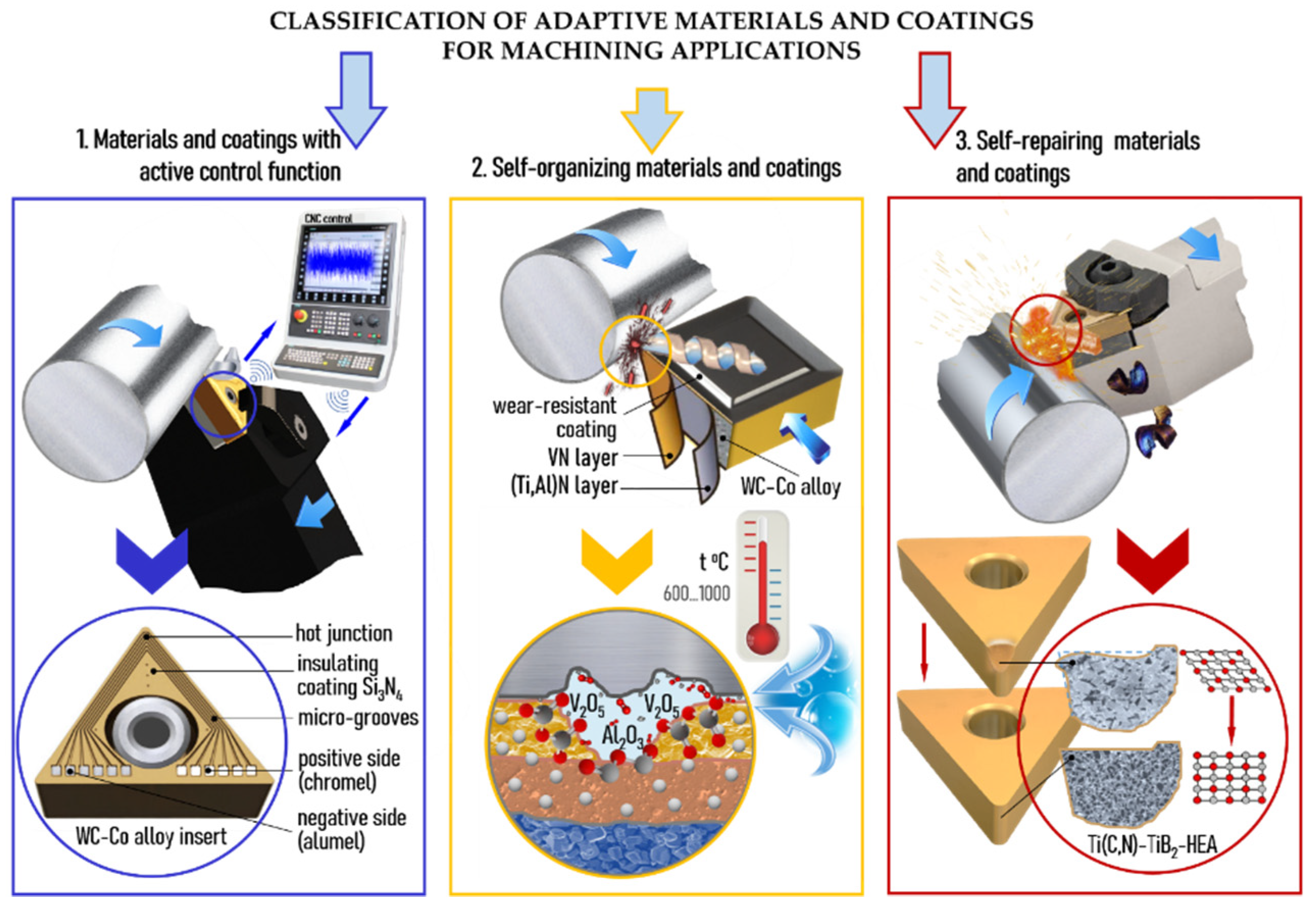
1.2. AMC Type Classification for Cutting Tools
- Materials and coatings with active control function;
- Self-organizing materials and coatings;
- Self-repairing materials and coatings.
1.3. Materials and Coatings with Active Control Function
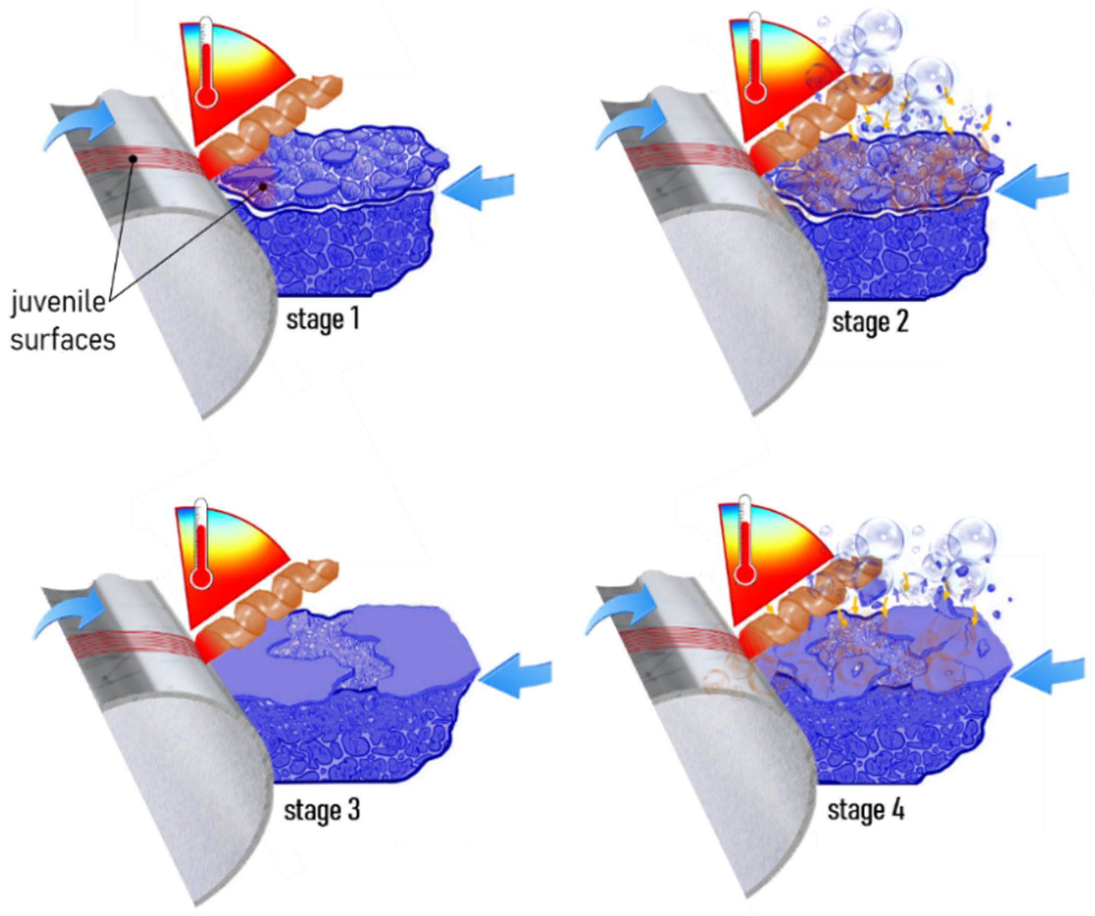
1.4. Self-Organizing Materials and Coatings
1.5. Self-Repairing Materials and Coatings
2. Materials and Methods
2.1. CPHSS-Based Tool Materials
- 100% HSS (basic version made of HS6-5-2C steel powder);
- CPHSS samples from 80% HSS, 20% TiC (option 1), 80% HSS, 15% TiC, 5% Al2O3 (option 2), 80% HSS, 20% TiCN (option 3).
2.2. Study of the Structure, Elemental Composition, and Tribological Properties
- Secondary ion mass spectrometry (SIMS) through analysis on an XT 300M mass spectrometer manufactured by Extorr Inc. (New Kensington, PA, USA);
- Auger electron spectroscopy (AES) by analysis on a JAMP-10S spectrometer manufactured by JEOL, Ltd. (Tokyo, Japan).
2.3. Investigation of Temperature Fields in the Cutting Wedge
2.4. Durability Testing of Cutting Tools
3. Results and Discussion
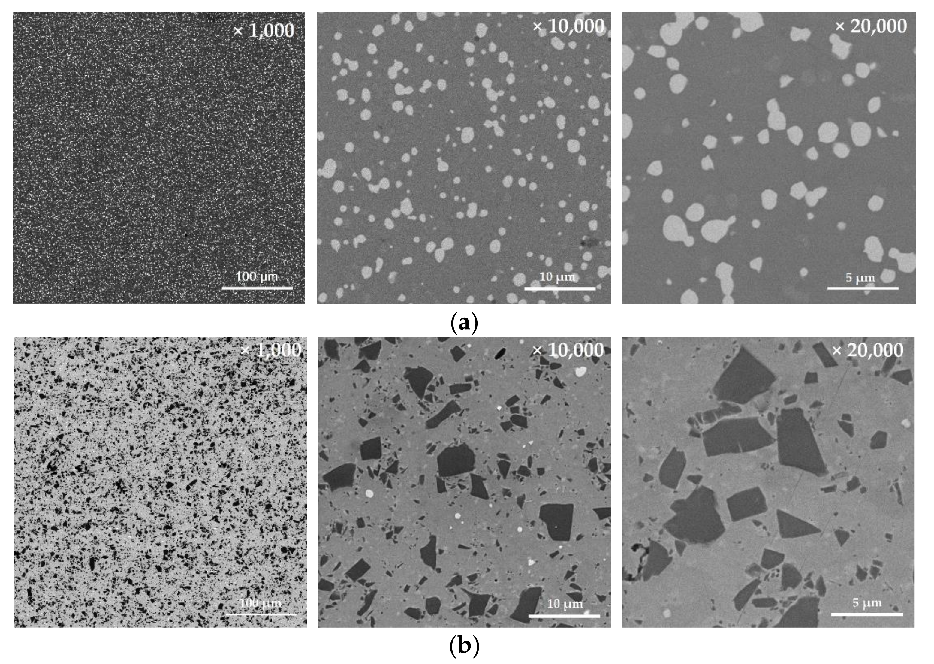
3.1. Material Structure Analysis
3.2. Testing of Tool Materials under Stationary Loads
3.3. Quantitative Assessment of the Cutting Part Wear and Roughness
3.4. Temperature Fields of the Cutting Wedge and Tribological Tests
3.5. Tribological Tests
- The COF curve does not have sharp bursts throughout the entire path, and its value remains at a low level from 0.3 to 0.5 (COF value upon heating has even lower values than those of a similar sample when tested without heating);
- The COF stabilizes even more and amounts to a little less than 0.45 after passing a path of 150 m. The sample containing 80% HSS, 20% TiC, and 5% Al2O3 demonstrates an intermediate value among the CPHSS samples in terms of tribological characteristics.
4. Conclusions
- materials and coatings with active control function;
- self-organizing materials and coatings;
- self-repairing materials and coatings.
Author Contributions
Funding
Institutional Review Board Statement
Informed Consent Statement
Data Availability Statement
Acknowledgments
Conflicts of Interest
References
- Zhu, S.; Cheng, J.; Qiao, Z.; Yang, J. High temperature solid-lubricating materials. Tribol. Int. 2019, 133, 206–223. [Google Scholar] [CrossRef]
- Fox-Rabinovich, G.S.; Gershman, I.S.; Veldhuis, S. Thin-film PVD coating metamaterials exhibiting similarities to natural processes under extreme tribological conditions. Nanomaterials 2020, 10, 1720. [Google Scholar] [CrossRef]
- Grigoriev, S.N.; Sobol, O.V.; Beresnev, V.M.; Serdyuk, I.V.; Pogrebnyak, A.D.; Kolesnikov, D.A.; Nemchenko, U.S. Tribological characteristics of (TiZrHfVNbTa)N coatings applied using the vacuum arc deposition method. J. Frict. Wear 2014, 35, 359–364. [Google Scholar] [CrossRef]
- Pogrebnjak, A.D.; Bagdasaryan, A.A.; Pshyk, A.; Dyadyura, K. Adaptive multicomponent nanocomposite coatings in surface engineering. Physics-Uspekhi 2017, 60, 586–607. [Google Scholar] [CrossRef]
- Muratore, C.; Voevodin, A.A. Chameleon coatings: Adaptive surfaces to reduce friction and wear in extreme environments. Annu. Rev. Mater. Res. 2009, 39, 297–324. [Google Scholar] [CrossRef] [Green Version]
- Aouadi, S.M.; Gu, J.; Berman, D. Self-healing ceramic coatings that operate in extreme environments: A review. J. Vac. Sci. Technol. A 2020, 38, 050802. [Google Scholar] [CrossRef]
- Bouzakis, K.-D.; Michailidis, N.; Skordaris, G.; Bouzakis, E.; Biermann, D.; M’Saoubi, R. Cutting with coated tools: Coating technologies, characterization methods and performance optimization. CIRP Ann. 2012, 61, 703–723. [Google Scholar] [CrossRef]
- Gershenson, C.; Fernández, N. Complexity and information: Measuring emergence, self-organization, and homeostasis at multiple scales. Complexity 2012, 18, 29–44. [Google Scholar] [CrossRef] [Green Version]
- Yeh, J.; Lin, S. Breakthrough applications of high-entropy materials. J. Mater. Res. 2018, 33, 3129–3137. [Google Scholar] [CrossRef]
- Feistel, R.; Ebeling, W. Introduction to the Field of Self-Organization, in Physics of Self-Organization and Evolution; Wiley-VCH Verlag GmbH & Co. KGaA: Weinheim, Germany, 2011; pp. 1–33. [Google Scholar]
- Grigoriev, S.N.; Vereschaka, A.A.; Vereschaka, A.S.; Kutin, A.A. Cutting tools made of layered composite ceramics with nano-scale multilayered coatings. Proc. CIRP 2012, 1, 301–306. [Google Scholar] [CrossRef]
- Sergevnin, V.S.; Blinkov, I.V.; Volkhonskii, A.O.; Belov, D.S.; Chernogor, A.V. Structure formation of adaptive arc-PVD Ti-Al-Mo-N and Ti-Al-Mo-Ni-N coatings and their wear-resistance under various friction conditions. Surf. Coat. Technol. 2019, 376, 38–43. [Google Scholar] [CrossRef]
- Shen, W.-J.; Tsai, M.-H.; Yeh, J.-W. Machining performance of sputter-deposited (Al0.34Cr0.22Nb0.11Si0.11Ti0.22)50N50 high-entropy nitride coatings. Coatings 2015, 5, 312–325. [Google Scholar] [CrossRef] [Green Version]
- Kovalev, A.; Wainstein, D.; Rashkovskiy, A. Investigation of anomalous physical properties of multilayer nanolaminate (TiAl)N/Cu coatings by electron spectroscopy techniques. Surf. Interface Anal. 2010, 42, 1361–1363. [Google Scholar] [CrossRef]
- Zekonyte, J.; Polcar, T. Friction force microscopy analysis of self-adaptive W-S-C coatings: Nanoscale friction and wear. ACS Appl. Mater. Interfaces 2015, 7, 21056–21064. [Google Scholar] [CrossRef] [PubMed] [Green Version]
- Yuan, J.; Yamamoto, K.; Covelli, D.; Tauhiduzzaman, M.; Arif, T.; Gershman, I.S.; Veldhuis, S.C.; Fox-Rabinovich, G.S. Tribo-films control in adaptive TiAlCrSiYN/TiAlCrN multilayer PVD coating by accelerating the initial machining conditions. Surf. Coat. Technol. 2016, 294, 54–61. [Google Scholar] [CrossRef]
- Vereschaka, A.S.; Grigoriev, S.N.; Tabakov, V.P.; Sotova, E.S.; Vereschaka, A.A.; Kulikov, M.Y. Improving the efficiency of the cutting tool made of ceramic when machining hardened steel by applying nano-dispersed multi-layered coatings. Key Eng. Mater. 2014, 581, 68–73. [Google Scholar] [CrossRef]
- Durmaz, Y.M.; Yildiz, F. The wear performance of carbide tools coated with TiAlSiN, AlCrN and TiAlN ceramic films in intelligent machining process. Ceram. Int. 2018, 45, 3839–3848. [Google Scholar] [CrossRef]
- Vereschaka, A.; Tabakov, V.; Grigoriev, S.; Aksenenko, A.; Sitnikov, N.; Oganyan, G.; Seleznev, A.; Shevchenko, S. Effect of adhesion and the wear-resistant layer thickness ratio on mechanical and performance properties of ZrN-(Zr,Al,Si)N coatings. Surf. Coat. Technol. 2019, 357, 218–234. [Google Scholar] [CrossRef]
- Li, Y.; Zheng, G.; Cheng, X.; Yang, X.; Xu, R.; Zhang, H. Cutting performance evaluation of the coated tools in high-speed milling of AISI 4340 steel. Materials 2019, 12, 3266. [Google Scholar] [CrossRef] [Green Version]
- Santecchia, E.; Hamouda, A.M.S.; Musharavati, F.; Zalnezhad, E.; Cabibbo, M.; Spigarelli, S. Wear resistance investigation of titanium nitride-based coatings. Ceram. Int. 2015, 41, 10349–10379. [Google Scholar] [CrossRef]
- Wang, B.; Liu, Z.; Cai, Y.; Luo, X.; Ma, H.; Song, Q.; Xiong, Z. Advancements in material removal mechanism and surface integrity of high speed metal cutting: A review. Int. J. Mach. Tool. Manuf. 2021, 166, 103744. [Google Scholar] [CrossRef]
- Chaus, A.S.; Sahul, M.; Moravcik, R.; Sobota, R. Role of microstructural factor in wear resistance and cutting performance of high-speed steel end mills. Wear 2021, 474, 203865. [Google Scholar]
- Malekan, M.; Bloch-Jensen, C.D.; Zolbin, M.A.; Orskov, K.B.; Jensen, H.M.; Aghababaei, R. Cutting edge wear in high-speed stainless steel end milling. Int. J. Adv. Manuf. Technol. 2021, 114, 2911–2928. [Google Scholar] [CrossRef]
- Kuzin, V.V.; Grigoriev, S.N.; Volosova, M.A. The role of the thermal factor in the wear mechanism of ceramic tools: Part 1. Macrolevel. J. Frict. Wear 2014, 35, 505–510. [Google Scholar] [CrossRef]
- Meng, X.; Lin, Y.; Mi, S. The research of tool wear mechanism for high-speed milling ADC12 aluminum alloy considering the cutting force effect. Materials 2021, 14, 1054. [Google Scholar] [CrossRef] [PubMed]
- Bremer, F.; Matthiesen, S. High-speed cutting with involute blades: Experimental research on cutting forces. J. Food Eng. 2021, 293, 110380. [Google Scholar]
- Kuzin, V.V.; Grigoriev, S.N.; Fedorov, M.Y. Role of the thermal factor in the wear mechanism of ceramic tools. Part 2: Microlevel. J. Frict. Wear 2015, 36, 40–44. [Google Scholar] [CrossRef]
- Li, J.; Tao, B.; Huang, S.; Yin, Z. Cutting tools embedded with thin film thermocouples vertically to the rake face for temperature measurement. Sens. Actuators A Phys. 2019, 296, 392–399. [Google Scholar] [CrossRef]
- Sugita, N.; Ishii, K.; Furusho, T.; Harada, K.; Mitsuishi, M. Cutting temperature measurement by a micro-sensor array integrated on the rake face of a cutting tool. CIRP Ann. 2015, 64, 77–80. [Google Scholar] [CrossRef]
- Li, J.; Tao, B.; Huang, S.; Yin, Z. Built-in thin film thermocouples in surface textures of cemented carbide tools for cutting temperature measurement. Sens. Actuators A Phys. 2018, 279, 663–670. [Google Scholar] [CrossRef]
- Plogmeyer, M.; González, G.; Schulze, V.; Bräuer, G. Development of thin-film based sensors for temperature and tool wear monitoring during machining. tm-Technisch. Messen 2020, 87, 768–776. [Google Scholar] [CrossRef]
- Cheng, K.; Niu, Z.C.; Wang, R.C.; Rakowski, R.; Bateman, R. Smart cutting tools and smart machining: Development approaches, and their implementation and application perspectives. Chin. J. Mech. Eng. 2017, 30, 1162–1176. [Google Scholar] [CrossRef] [Green Version]
- Ting, Y.; Suprapto; Nugraha, A.; Chiu, C.W.; Gunawan, H. Design and characterization of one-layer PVDF thin film for a 3D force sensor. Sens. Actuators A Phys. 2016, 250, 129–137. [Google Scholar] [CrossRef]
- Luo, M.; Luo, H.; Axinte, D.; Liu, D.; Mei, J.; Liao, Z. A wireless instrumented milling cutter system with embedded PVDF sensors. Mech. Syst. Signal. Process. 2018, 110, 556–568. [Google Scholar] [CrossRef] [Green Version]
- Sobol, O.V.; Andreev, A.A.; Grigoriev, S.N.; Gorban, V.F.; Volosova, M.A.; Aleshin, S.V.; Stolbovoi, V.A. Effect of high-voltage pulses on the structure and properties of titanium nitride vacuum-arc coatings. Met. Sci. Heat Treat. 2012, 54, 195–203. [Google Scholar] [CrossRef]
- Sergevnin, V.S.; Blinkov, I.V.; Volkhonskii, A.O.; Belov, D.S.; Kuznetsov, D.V.; Gorshenkov, M.V.; Skryleva, E.A. Wear behaviour of wear-resistant adaptive nano-multilayered Ti-Al-Mo-N coatings. Appl. Surf. Sci. 2016, 388, 13–23. [Google Scholar] [CrossRef]
- Wainstein, D.; Kovalev, A. Tribooxidation as a way to improve the wear resistance of cutting tools. Coatings 2018, 8, 223. [Google Scholar] [CrossRef] [Green Version]
- Voitov, V.; Stadnychenko, V.; Varvarov, V.; Stadnychenko, N. Mechanisms of self-organization in tribosystems operating under conditions of abnormally low friction and wear. Adv. Mech. Eng. 2020, 12, 1687814020963843. [Google Scholar] [CrossRef]
- Podgursky, V.; Bogatov, A.; Yashin, M.; Sobolev, S.; Gershman, I.S. Relation between Self-Organization and wear mechanisms of diamond films. Entropy 2018, 20, 279. [Google Scholar] [CrossRef] [PubMed] [Green Version]
- Erdemir, A.; Eryilmaz, O. Achieving superlubricity in DLC films by controlling bulk, surface, and tribochemistry. Friction 2014, 2, 140–155. [Google Scholar] [CrossRef] [Green Version]
- Fominski, V.Yu.; Grigoriev, S.N.; Gnedovets, A.G.; Romanov, R.I. Pulsed laser deposition of composite Mo–Se–Ni–C coatings using standard and shadow mask configuration. Surf. Coat. Technol. 2012, 206, 5046–5054. [Google Scholar] [CrossRef]
- Barszcz, M.; Pashechko, M.; Dziedzic, K.; Jozwik, J. Study on the self-organization of an Fe-Mn-C-B Coating during friction with surface-active lubricant. Materials 2020, 13, 3025. [Google Scholar] [CrossRef]
- Liu, Z.L.; Messer-Hannemann, P.; Laube, S.; Greiner, C. Tribological performance and microstructural evolution of alpha-brass alloys as a function of zinc concentration. Friction 2020, 8, 1117–1136. [Google Scholar] [CrossRef]
- Sobol, O.V.; Andreev, A.A.; Grigoriev, S.N.; Gorban, V.F.; Volosova, M.A.; Aleshin, S.V.; Stolbovoy, V.A. Physical characteristics, structure and stress state of vacuum-arc TiN coating, deposition on the substrate when applying high-voltage pulse during the deposition. Probl. Atom. Sci. Tech. 2011, 4, 174–177. [Google Scholar]
- Gnyusov, S.F.; Ignatov, A.A.; Durakov, V.G.; Tarasov, S. Yu. The effect of thermal cycling by electron-beam surfacing on structure and wear resistance of deposited M2 steel. Appl. Surf. Sci. 2012, 263, 215–222. [Google Scholar] [CrossRef]
- Vereschaka, A.A.; Volosova, M.A.; Grigoriev, S.N.; Vereschaka, A.S. Development of wear-resistant complex for high-speed steel tool when using process of combined cathodic vacuum arc deposition. Procedia CIRP 2013, 9, 8–12. [Google Scholar] [CrossRef] [Green Version]
- Naumov, A.G.; Latyshev, V.N.; Novikov, V.V.; Afanasyeva, O.V.; Komelkov, V.A. On the kinetics of forming an oxide film for lubrication when cutting steel in a controlled atmosphere. J. Frict. Wear 2017, 38, 364–368. [Google Scholar] [CrossRef]
- Gershman, I.; Mironov, A.; Podrabinnik, P.; Kuznetsova, E.; Gershman, E.; Peretyagin, P. Relationship of secondary structures and wear resistance of antifriction aluminum alloys for journal bearings from the point of view of self-organization during friction. Entropy 2019, 21, 1048. [Google Scholar] [CrossRef] [Green Version]
- Brizmer, V.; Stadler, K.; van Drogen, M.; Han, B.; Matta, C.; Piras, E. The tribological performance of black oxide coating in rolling/sliding contacts. Tribol. Trans. 2017, 60, 557–574. [Google Scholar] [CrossRef]
- Sobol, O.V.; Andreev, A.A.; Grigoriev, S.N.; Volosova, M.A.; Gorban, V.F. Vacuum-arc multilayer nanostructured TiN/Ti coatings: Structure, stress state, properties. Met. Sci. Heat. Treat. 2012, 54, 28–33. [Google Scholar] [CrossRef]
- Fergus, J.W.; Mallipedi, C.V.S.; Edwards, D.L. Silver/silver-oxide composite coating for intrinsically adaptive thermal regulation. Compos. Part B-Eng. 1998, 29, 51–56. [Google Scholar] [CrossRef]
- Volosova, M.A.; Grigor’ev, S.N.; Kuzin, V.V. Effect of titanium nitride coating on stress structural inhomogeneity in oxide-carbide ceramic. Part 4. Action of heat flow. Refract. Ind. Ceram. 2015, 56, 91–96. [Google Scholar] [CrossRef]
- Zhou, Z.; Rainforth, W.M.; Rother, B.; Ehiasarian, A.P.; Hovsepian, P.E.; Munz, W.D. Elemental distributions and substrate rotation in industrial TiAlN/VN superlattice hard PVD coatings. Surf. Coat. Technol. 2004, 183, 275–282. [Google Scholar] [CrossRef]
- Hahn, R.; Bartosik, M.; Soler, R.; Kirchlechner, C.; Dehm, G.; Mayrhofer, P.H. Superlattice effect for enhanced fracture toughness of hard coatings. Scr. Mater. 2016, 124, 67–70. [Google Scholar] [CrossRef] [Green Version]
- Comakli, O. Influence of CrN, TiAlN monolayers and TiAlN/CrN multilayer ceramic films on structural, mechanical and tribological behavior of beta-type Ti45Nb alloys. Ceram. Int. 2020, 46, 8185–8191. [Google Scholar] [CrossRef]
- Li, M.L.; Wang, E.Q.; Yue, J.L.; Huang, X.Z. Microstructure, mechanical and tribological property of TiAlN/VN nano-multilayer films. J. Inorg. Mater. 2017, 32, 1280–1284. [Google Scholar]
- Metel, A.; Bolbukov, V.; Volosova, M.; Grigoriev, S.; Melnik, Y. Equipment for deposition of thin metallic films bombarded by fast argon atoms. Instrum. Exp. Tech. 2014, 57, 345–351. [Google Scholar] [CrossRef]
- Grigoriev, S.N.; Metel, A.S.; Fedorov, S.V. Modification of the structure and properties of high-speed steel by combined vacuum-plasma treatment. Met. Sci. Heat. Treat. 2012, 54, 8–12. [Google Scholar] [CrossRef]
- Metel, A.S.; Grigoriev, S.N.; Melnik, Y.A.; Bolbukov, V.P. Characteristics of a fast neutral atom source with electrons injected into the source through its emissive grid from the vacuum chamber. Instrum. Exp. Tech. 2012, 55, 288–293. [Google Scholar] [CrossRef]
- Grigoriev, S.N.; Melnik, Y.A.; Metel, A.S.; Panin, V.V.; Prudnikov, V.V. A compact vapor source of conductive target material sputtered by 3-keV ions at 0.05-Pa pressure. Instrum. Exp. Tech. 2009, 52, 731. [Google Scholar] [CrossRef]
- Lakhotkin, Y.V.; Aleksandrov, S.; Zhuk, Y. Self-Sharpening Cutting Tool with Hard Coating. US Patent 7166371-B2, 23 January 2007. [Google Scholar]
- Robertson, S.W.; Mehta, A.; Pelton, A.R.; Ritchie, R.O. Evolution of crack-tip transformation zones in superelastic Nitinol subjected to in situ fatigue: A fracture mechanics and synchrotron X-ray microdiffraction analysis. Acta Mater. 2007, 55, 6198–6207. [Google Scholar] [CrossRef]
- Silva, N.J.; De Araujo, C.J.; Gonzalez, C.H.; Grassi, E.N.D.; Oliveira, C.A.N. Comparative study of dynamic properties a NiTi alloy with shape memory and classical structural materials. Materials 2011, 16, 830–835. [Google Scholar]
- Roytburd, A.L. Principal concepts of martensitic theory. J. Phys. IV 1995, 05, 21–30. [Google Scholar] [CrossRef]
- Razov, A.I. Application of titanium nickelide–based alloys in engineering. Phys. Met. Metallogr. 2004, 97, 97–126. [Google Scholar]
- Devin, L.N.; Osadchii, A.A. Improving performance of cBN cutting tools by increasing their damping properties. J. Superhard. Mater. 2012, 34, 328–335. [Google Scholar] [CrossRef]
- Fu, Z.; Koc, R. Processing and characterization of TiB2-TiNiFeCrCoAl high-entropy alloy composite. J. Am. Ceram. Soc. 2017, 100, 2803–2813. [Google Scholar] [CrossRef]
- Li, Z.; Zhu, C.; Cai, B.; Chang, F.; Liu, X.; Naeem, M.Z.; Dai, P. Effect of TiB2 content on the microstructure and mechanical properties of Ti(C,N) TiB2-FeCoCrNiAl high-entropy alloys composite cermets. J. Ceram. Soc. Jpn. 2020, 128, 66–74. [Google Scholar] [CrossRef]
- Du, R.; Gao, Q.; Wu, S.; Lu, S.; Zhou, X. Influence of TiB2 particles on aging behavior of in-situ TiB2/Al-4.5Cu composites. Mater. Sci. Eng. A Struct. Mater. 2018, 721, 244–250. [Google Scholar] [CrossRef]
- Chen, C.S.; Yang, C.C.; Chai, H.Y.; Yeh, J.W.; Chau, J.L.H. Novel cermet material of WC/multi-element alloy. Int. J. Refract. Hard Mater. 2014, 43, 200–204. [Google Scholar] [CrossRef]
- Zhang, W.; Zhang, M.Y.; Peng, Y.B.; Wang, L.; Liu, Y.; Hu, S.H.; Hu, Y. Interfacial structures and mechanical properties of a high entropy alloy-diamond composite. Int. J. Refract. Met. Hard Mater. 2020, 86, 105109. [Google Scholar] [CrossRef]
- Grigoriev, S.; Peretyagin, P.; Smirnov, A.; Solis, W.; Diaz, L.A.; Fernandez, A.; Torrecillas, R. Effect of graphene addition on the mechanical and electrical properties of Al2O3-SiCw ceramics. J. Eur. Ceram. Soc. 2017, 37, 2473–2479. [Google Scholar] [CrossRef]
- Fominski, V.Yu.; Grigoriev, S.N.; Celis, J.P.; Romanov, R.I.; Oshurko, V.B. Structure and mechanical properties of W-Se-C/diamond-like carbon and W-Se/diamond-like carbon bi-layer coatings prepared by pulsed laser deposition. Thin Solid Films 2012, 520, 6476–6483. [Google Scholar] [CrossRef]
- Metel, A.S.; Grigoriev, S.N.; Melnik, Y.A.; Panin, V.V. Filling the vacuum chamber of a technological system with homogeneous plasma using a stationary glow discharge. Plasma Phys. Rep. 2009, 35, 1058–1067. [Google Scholar] [CrossRef]
- BS EN ISO 4957; Tool Steels; BSI: London, UK, 2018.
- Pellizzari, M.; Fedrizzi, A.; Zadra, M. Spark plasma co-sintering of hot work and high speed steel powders for fabrication of a novel tool steel with composite microstructure. Powder Technol. 2011, 214, 292–299. [Google Scholar] [CrossRef]
- Krioni, N.K.; Migranov, M.S.; Fox-Rabinovich, G.S.; Shuster, L.S. Study of the tribotechnical properties of a cutting tool made of sintered powder tool materials. J. Frict. Wear 2018, 39, 12–18. [Google Scholar] [CrossRef]
- Hadian, A.; Zamani, C.; Clemens, F.J. Effect of sintering temperature on microstructural evolution of M48 high speed tool steel bonded NbC matrix cemented carbides sintered in inert atmosphere. Int. J. Refract. Met. Hard Mater. 2018, 74, 20–27. [Google Scholar] [CrossRef]
- Zhang, F.; Luo, P.; Ouyang, Q.; He, Q.; Hu, M.; Li, S. Microstructure and mechanical properties of b4c-blended M3:2 high-speed steel powders consolidated by sintering and heat treatment. J. Mater. Eng. Perform. 2019, 28, 6145–6156. [Google Scholar] [CrossRef]
- ASTM G99–17; Standard Test Method for Wear Testing with a Pin-on-Disk Apparatus; ASTM International: West Conshohocken, PA, USA, 2017; Volume 03.02.
- Xin, H.; Shi, Y.; Ning, L. Tool wear in disk milling grooving of titanium alloy. Adv. Mech. Eng. 2016, 8, 1687814016671620. [Google Scholar] [CrossRef] [Green Version]
- DIN 17210; Case Hardening Steels Technical Delivery Conditions; Deutsches Institut fur Normung E.V. (DIN): Berlin, Germany, 1986.
- Kropotkina, E.; Zykova, M.; Shein, A.; Kapustina, N. Application of roller burnishing technologies to improve the wear resistance of submerged pump parts made of powder alloys. Mech. Ind. 2018, 19, 705. [Google Scholar] [CrossRef]
- Fan, X.; Loftus, M. The influence of cutting force on surface machining quality. Int. J. Prod. Res. 2007, 45, 899–911. [Google Scholar] [CrossRef]
- Zhao, J.; Liu, Z. Influences of coating thickness on cutting temperature for dry hard turning Inconel 718 with PVD TiAlN coated carbide tools in initial tool wear stage. J. Manuf. Process. 2020, 56, 1155–1165. [Google Scholar] [CrossRef]
- Kuzin, V.V.; Grigor’ev, S.N.; Volosova, M.A. Effect of a TiC coating on the stress-strain state of a plate of a high-density nitride ceramic under nonsteady thermoelastic conditions. Refract. Ind. Ceram. 2014, 54, 376–380. [Google Scholar] [CrossRef]
- Akbar, F.; Arsalan, M. Thermal modelling of cutting tool temperatures and heat partition in orthogonal machining of high-strength alloy steel. Proc. Inst. Mech. Eng. B J. Eng. 2021, 235, 1309–1326. [Google Scholar] [CrossRef]
- Metel, A.; Grigoriev, S.; Melnik, Y.; Panin, V.; Prudnikov, V. Cutting tools nitriding in plasma produced by a fast neutral molecule beam. Jpn. J. Appl. Phys. 2011, 50, 08JG04. [Google Scholar] [CrossRef]
- Zhao, J.; Liu, Z.; Wang, B.; Hu, J.; Wan, Y. Tool coating effects on cutting temperature during metal cutting processes: Comprehensive review and future research directions. Mech. Syst. Signal. Process. 2021, 150, 107302. [Google Scholar] [CrossRef]
- Ivashchenko, V.I.; Turchi, P.E.A.; Gonis, A.; Ivashchenko, L.A.; Skrynskii, P.L. Electronic origin of elastic properties of titanium carbonitride alloys. Metall. Mater. Trans. A 2006, 37, 3391–3396. [Google Scholar] [CrossRef]
- Soković, M.; Bahor, M. On the inter-relationships of some machinability parameters in finish machining with cermet TiN (PVD) coated tools. J. Mater. Process. Technol. 1998, 78, 163–170. [Google Scholar] [CrossRef]
- Chen, R.; Tu, J.P.; Liu, D.G.; Mai, Y.J.; Gu, C.D. Microstructure, mechanical and tribological properties of TiCN nanocomposite films deposited by DC magnetron sputtering. Surf. Coat. Technol. 2011, 205, 5228–5234. [Google Scholar] [CrossRef]
- Lengauer, W.; Scagnetto, F. Ti(C,N)-based cermets: Critical review of achievements and recent developments. Solid State Phenom. 2018, 274, 53–100. [Google Scholar] [CrossRef]


| Material | Rockwell Hardness HRC | Flexural Strength, MPa | Average Coefficient of Friction on Steel |
|---|---|---|---|
| 100% HSS | 63–65 | 3300 | 0.75 |
| CPHSS | 70–72 | 2400–2500 | 0.5–0.6 |
| Parameter | Value and Description |
|---|---|
| Motion pattern | Rotation of the sample (disc) relative to a stationary counter body |
| Counter body | A pin made of 100Cr6 steel with a diameter of 6 mm |
| Applied load, N | 1 |
| Radius of movement, mm | 2 |
| Sliding speed, cm/s | 10 |
| Test temperature, °C | +20.0, 600.0 |
Publisher’s Note: MDPI stays neutral with regard to jurisdictional claims in published maps and institutional affiliations. |
© 2021 by the authors. Licensee MDPI, Basel, Switzerland. This article is an open access article distributed under the terms and conditions of the Creative Commons Attribution (CC BY) license (https://creativecommons.org/licenses/by/4.0/).
Share and Cite
Grigoriev, S.N.; Migranov, M.S.; Melnik, Y.A.; Okunkova, A.A.; Fedorov, S.V.; Gurin, V.D.; Volosova, M.A. Application of Adaptive Materials and Coatings to Increase Cutting Tool Performance: Efficiency in the Case of Composite Powder High Speed Steel. Coatings 2021, 11, 855. https://doi.org/10.3390/coatings11070855
Grigoriev SN, Migranov MS, Melnik YA, Okunkova AA, Fedorov SV, Gurin VD, Volosova MA. Application of Adaptive Materials and Coatings to Increase Cutting Tool Performance: Efficiency in the Case of Composite Powder High Speed Steel. Coatings. 2021; 11(7):855. https://doi.org/10.3390/coatings11070855
Chicago/Turabian StyleGrigoriev, Sergey N., Mars S. Migranov, Yury A. Melnik, Anna A. Okunkova, Sergey V. Fedorov, Vladimir D. Gurin, and Marina A. Volosova. 2021. "Application of Adaptive Materials and Coatings to Increase Cutting Tool Performance: Efficiency in the Case of Composite Powder High Speed Steel" Coatings 11, no. 7: 855. https://doi.org/10.3390/coatings11070855