Article

Tailoring Periodic Vertical Cracks in Thermal Barrier Coatings Enabling High Strain Tolerance

State Key Laboratory for Mechanical Behavior of Materials, School of Materials Science and Engineering, Xi’an Jiaotong University, Xi’an 710049, China
*
Author to whom correspondence should be addressed.
Coatings 2021, 11(6), 720; https://doi.org/10.3390/coatings11060720
Submission received: 23 May 2021 / Revised: 10 June 2021 / Accepted: 13 June 2021 / Published: 16 June 2021

Abstract

:
Lifetime is a basic support for the thermal insulation function of thermal barrier coatings (TBCs). Therefore, extending the life span is essential to develop next-generation TBCs. For this objective, the columnar structure formed by vertical cracks appears to make sense. However, the underlying mechanism is still unclear. This work scrutinizes the influence of periodic vertical cracks on cracking behavior in order to tailor high strain tolerant TBCs. A finite element model was evolved to explore the crack behavior influenced by thermal mismatch strain between substrate and coating. The virtual crack closure technique (VCCT) was used to describe the propagation of crack under load. It is found clearly that the space between two vertical cracks (short for SVC) along the in-plane direction has a noteworthy influence on the strain tolerance of TBCs. Results indicate that the strain energy release rate (SERR) and stresses at the pre-crack tip increase continuously with the increase of the SVC, suggesting that the driving force for cracks is increasing. The crack is not propagated when the SVC is very small, whereas the crack grows continuously with the increase of the SVC. The growth of a crack can be prevented by reducing the SVC. A critical value for the SVC was found. When the SVC is less than the critical value, the SERR can be dramatically reduced. Thus, the SVC of periodic cracks can be tailored to obtain TBCs with high strain tolerance.

1. Introduction

The working temperature of advanced land-based gas turbines and aircraft engines continue to increase upon their thrust/weight ratio and performance. The working temperature of turbine-blades rises with the improvement in the thrust-to-weight proportion of aircraft engines. For widely used metallic parts, for example, turbine-blades, vanes, nozzles, and combustors, the high working temperature causes a major challenge. Indeed, the working temperature surpasses the break point temperature that these metallic components can bear [1,2,3,4,5]. For example, the working temperature is mostly greater than 1600 K, while the limit bearing temperature is below 1400 K even for advanced nickel-based single crystal alloys [6,7]. The TBCs give thermal protection to metallic parts to work at elevated temperatures over their sustainable limit. In the last few decades, TBCs have been used in numerous applications, working at elevated temperatures [8,9,10,11,12].
A long life span is essential for advanced TBCs. However, the failure of top-coat (TC) is still an issue for current TBCs, especially for the atmospheric plasma sprayed top-coat (APS-TC). Generally, the TC is deposited either by electron beam physical vapor deposition (EB-PVD) or atmospheric plasma spraying (APS) [13,14,15,16,17]. In industrial applications, APS is regularly used to deposit the TC due to its operational simplicity, low maintenance cost, and probability to deposit thick TC up to 2 mm [18]. Normally, EB-PVD-TCs show a columnar grains structure and APS-TCs show a lamellar structure. The strain tolerance of columnar-structured coatings is higher due to a smaller increase in global elastic modulus during thermal shock resistance [19], which extends the lifespan of TBCs [20,21,22,23,24]. In APS-TC, the micro-pores and cracks are dispensed haphazardly and resulted in low thermal conductivity. However, a short life span is the drawback of APS-TBCs. The failure of TBCs is mainly the spallation of top-coat [25]. At an as-deposited state, a crack network is formed which is due to the linkage of inter-splat pores and intra-splat cracks. After thermal exposure, the micro-cracks would be propagated in any direction in ceramic coatings [26]. In particular, the propagation of cracks between splats along coating surface is easier attributed to the orientations of inter-splat pores.
The thermal spallation of thermally exposed TBCs was attributed to the residual stress and thermal mismatch stress. The difference between the coefficients of thermal expansion (TEC) of the top-coat (TC) and metallic substrate (SUB) when temperatures change between room temperature and elevated temperatures, is the main reason for the thermal mismatch stress in TBCs [27,28,29]. Residual stress starts appearing during the early stage of deposition, and continuously develops until the complete degradation of coating. As the residual stress depends on strain velocity, the prediction of residual stress is very complex [30]. The main reasons for residual stress are quenching during solidification, highly thermal mismatch, and geometric discontinuities [31].
During thermal cycling, thermal mismatch stress would be continuously regenerated. Consequently, high residual stresses are produced near the defects, i.e., interfaces and micro-cracks. One crack meets with its neighboring cracks. Crack adhesion results in coating delamination, which is answerable to a definitive failure of TBCs [25]. Additionally, at elevated temperatures, the TC sintering has a harmful influence on coating failure, which would enlarge the driving force for spallation. The delamination of the lamellar coating due to sintering was investigated in [32], which recommended various essential design methods for a higher thermal lifetime. To improve the coatings delamination resistance, various efforts, such as a multi-layer design for TC and the development of a new material, have been made [33,34,35,36,37,38,39]. However, the results were not very effective, since sintering induced stiffening is inevitable during high temperature exposure. Therefore, it is necessary to further recognize the short life span of coatings, and to recommend suitable optimization methods for coatings.
The failure mechanisms of coatings are regularly controlled by the magnitude of the crack-driving force and the maximum residual stresses. The propagation of crack/coating fracture occurs as the material is damaged or layers are separated from one another due to the external load [40,41]. By the development of finite element modeling (FEM) [42,43], various techniques, such as cohesive zone model, the conventional finite element method (CFEM), the extended finite element method (XFEM), and VCCT, can be utilized to simulate the propagation of the crack [27,44,45,46] and find the strain energy at the tip of crack [47]. Among many techniques, VCCT is an attractive technique to evaluate the fracture behavior of ceramic coatings because the data required are nodal displacement beyond the tip of the crack and nodal force at the tip of crack [27,48].
The propagation and combination of cracks leads to the spallation of coating, which is one of the most popular failure modes during the service of plasma sprayed ceramic coatings. Recently, investigations have been concerned with the delamination of films from the substrate, and the relations between vertical pores and degradation of TC. Lu and Erdogan et al. [49] analytically examined the solitary fields close and at the convergence point of interfacial degradation of a vertical crack. The reallocation of interfacial stress resulting from the periodic segmentation cracks has been numerically examined in the coating by Wu et al. [50]. Zhou and Kokini et al. [51,52] analytically examined the interfacial fracture mechanism of the TBC system with multiple vertical cracks. In our previous paper [53], the strain tolerant design was elaborated by embedding vertical cracks in coatings. The results show that the crack-driving force was reduced as the number and depth of vertical cracks increased. Therefore, the coatings including vertical cracks had high crack resistance, especially for the thick coatings [54]. This result suggests that coatings with vertical cracks increase strain tolerance, which has a significant influence on the preparation and design of advanced protective coatings in future applications. However, many previous investigations have disregarded the interaction of vertical cracks and propagation of cracks, while a few studies investigate the influence of crack space on the coating delamination and the durability of the TBCs [51,52,53,55]. This is the original motivation of the present study.
This work develops a finite element model to explore the crack behavior induced by thermal mismatch strain between substrate and coating. The influence of periodic vertical cracks on cracking behavior was investigated in order to tailor high strain tolerant TBCs.

2. Model Development

2.1. TBC System Model

In this work, the TBCs consisted of three layers, SUB, BC, and TC. The TBC model was designed using commercially available FEM software ABAQUS 6.14. Figure 1 shows the finite element model geometry and the mesh used in the simulation. htc, hbc, and hsub represent the thicknesses of TC, BC and SUB, chosen as 3 mm, 150 µm, and 5 mm, respectively. The much thicker TC can be prominent in the strain tolerant design. The effect of the SVC (L) on crack growth could be investigated here. Therefore, the SVC was chosen to be different. In the TC, a pre-crack is inserted along the surface of coating, as shown in Figure 1a. In this TBC model, “a” means the pre-crack length, referring to 5 µm, and “b” is the vertical distance between pre-crack and TC/BC interference, which is 150 µm. The numbers 1, 2, and 3 represent axes, i.e., x-axis, y-axis, and z-axis, respectively.
The present FEM is based on the following assumptions: (1) The SUB, BC layer, and TC layer on one side with pre-existing crack are isotropic and homogeneous; (2) The geometric morphology at the TC/BC and BC/SUB interference is flat; (3) The vertical cracks were only inserted into the TC.
In this work, models with different SVC were investigated. For simulation, a representative unit-cell was used because the model is in periodic symmetry. This pre-crack along the coating surface exhibits a chain of cracks. When this pre-crack grows in the model to the left side, the spallation of coating will occur when it connects with the cracks in the neighboring region. The residual stresses will be determined under different SVC. The VCCT on the basis of fracture mechanics concepts [27] was used to determine the SERR at the pre-crack tip. The regular quadrilateral was utilized to mesh the model and complete meshed model, as shown in Figure 1b. Close to the interface and crack region, the mesh refinement is accomplished to show the stress at the crack tip. Figure 1c is a detailed representation of the refining mesh region. The mesh size has no effect on the SERR at the crack tip due to the dense mesh grid.

2.2. Boundary Conditions

The ceramic TC layer was taken to be linear elastic materials, whereas the bond-coat and substrate were taken to be elastic–plastic materials [55]. The detailed mechanical and thermal properties such as TEC, Poisson ratio, and Young’s modulus of TC, BC, and SUB are listed in Table 1 [56,57,58,59].
Since the representative unit of the model is extracted from the coating sample, the periodic boundary conditions were used. At the right edge of the model, the periodic boundary constraint is represented in Figure 1b. This periodic boundary constraint shows that all nodes on the edge of the model will have an equal distance in the x-direction. Concurrently, these nodes are permitted to budge in the x-direction without any restriction. A strain (0.4%) is applied on the left edge on the model, which is to model mismatch strain between SUB and TC. Furthermore, the nodes located at the bottom edge of the model are contrived in the y-direction, which can avoid movement of the rigid-body.

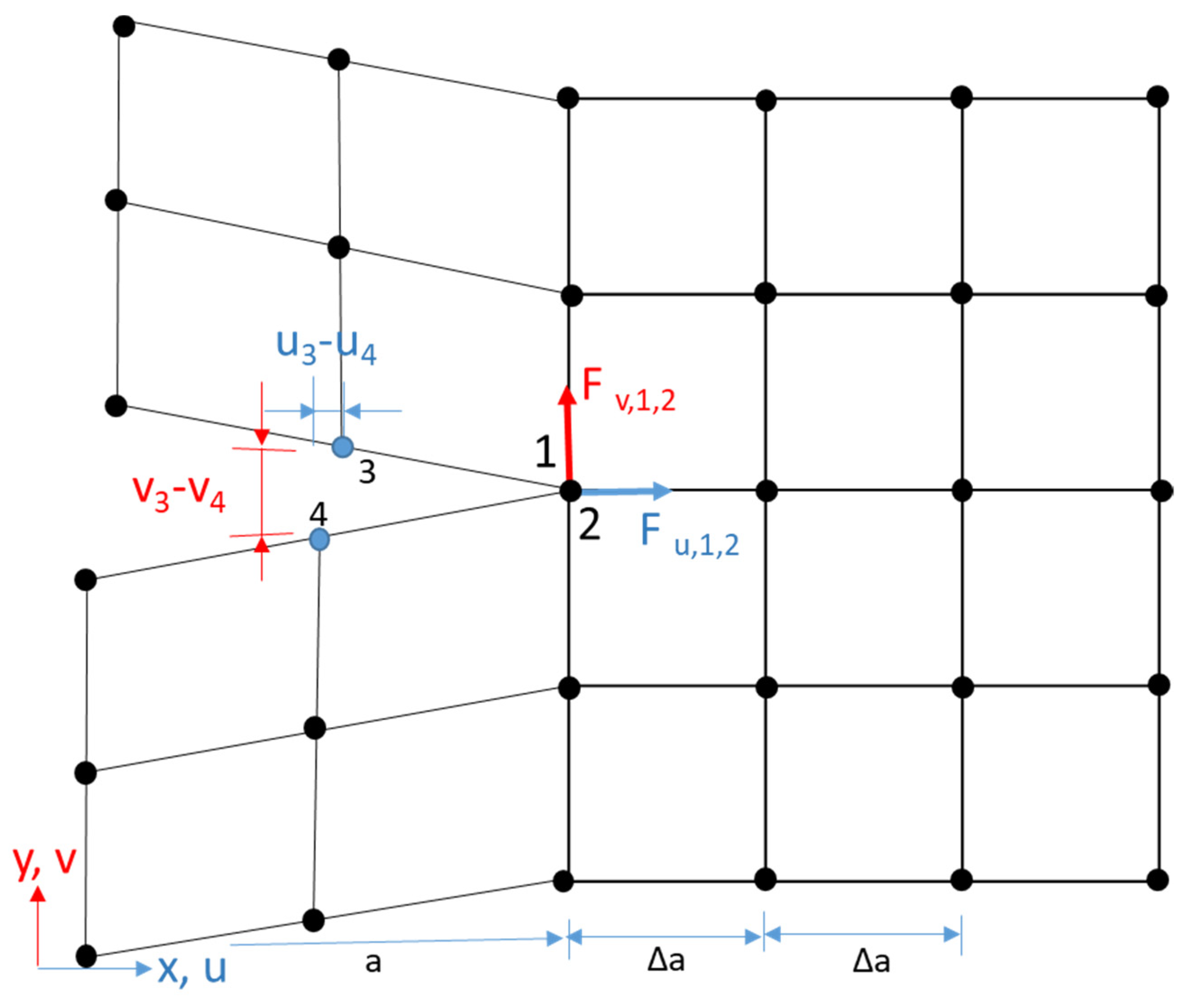
2.3. Cracking Description

In the present study, the growth of the crack in TC is described using a “Debond” technique in software Abaqus. Meanwhile, this technique is a robust fit to simulate the crack of ceramic materials, based on a linear elastic fracture mechanism (LEFM). In this technique, the path of crack growth is defined in advance. The node-pair at the tip of the crack is debonded when the fracture parameter at the tip of crack approaches the critical value. Here, the VCCT criterion is used to obtain the SERR at the crack tip.
Irwin et al. [60] proposed the SERR, which means the required energy to generate a new crack with ∆A area. Many techniques can be utilized to find the energy at the crack tip, such as a local virtual crack extension technique, VCCT, and global virtual crack extension technique. The VCCT is the most efficient convenient technique compared to other techniques because the data required are displacement behind the crack tip and nodal force at the tip of crack. The nodal displacement and force for any FE software are basic variables. The components GI and GII of SERR can be obtained easily using the VCCT technique. The VCCT graphic diagram for the first-order element with four nodes is shown in Figure 2. Equations (1) and (2) can be used to determine the SERR GI and GII components.
G I = F v , 1 , 2 Δ v 2 B Δ a = F v , 1 , 2 v 3 v 4 2 B Δ a
G II = F u , 1 , 2 Δ u 2 B Δ a = F u , 1 , 2 u 3 u 4 2 B Δ a
where ui and Fu,1,2 are nodal displacement components beyond the tip of the crack and force component at the crack tip, respectively, along the x-direction. The parameters vi and Fv,1,2 are nodal displacement components beyond the tip of the crack and force component at the crack tip, respectively, along the y-direction. The Δa and B are characteristic element length and thickness along third-direction, respectively, and its value for a two-dimensional model is 1.0.
The crack growth can be controlled in TBCs during thermal cycling by fracture modes I and II. In this study, a power law is employed for fracture criterion of crack growth in TC, which is expressed as:
G equiv G equivc = G I G IC a m + G II G IIC a n
where parameters Gequivc and Gequiv are critical equivalent and equivalent strain energy, GIC is a critical SERR of mode I, and GIIC is critical SERR of mode II. The parameters an and am are exponents, and the values were set as 1.0 for both an and am [25,61].

3. Results and Discussion

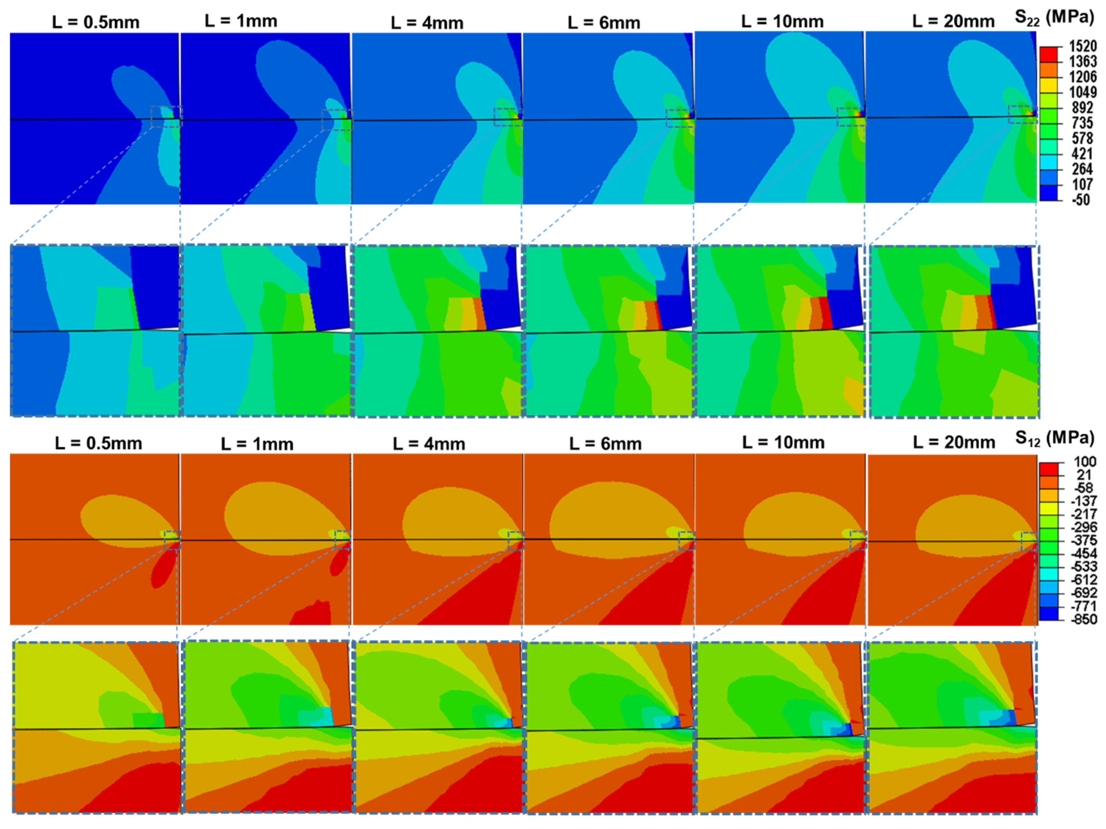
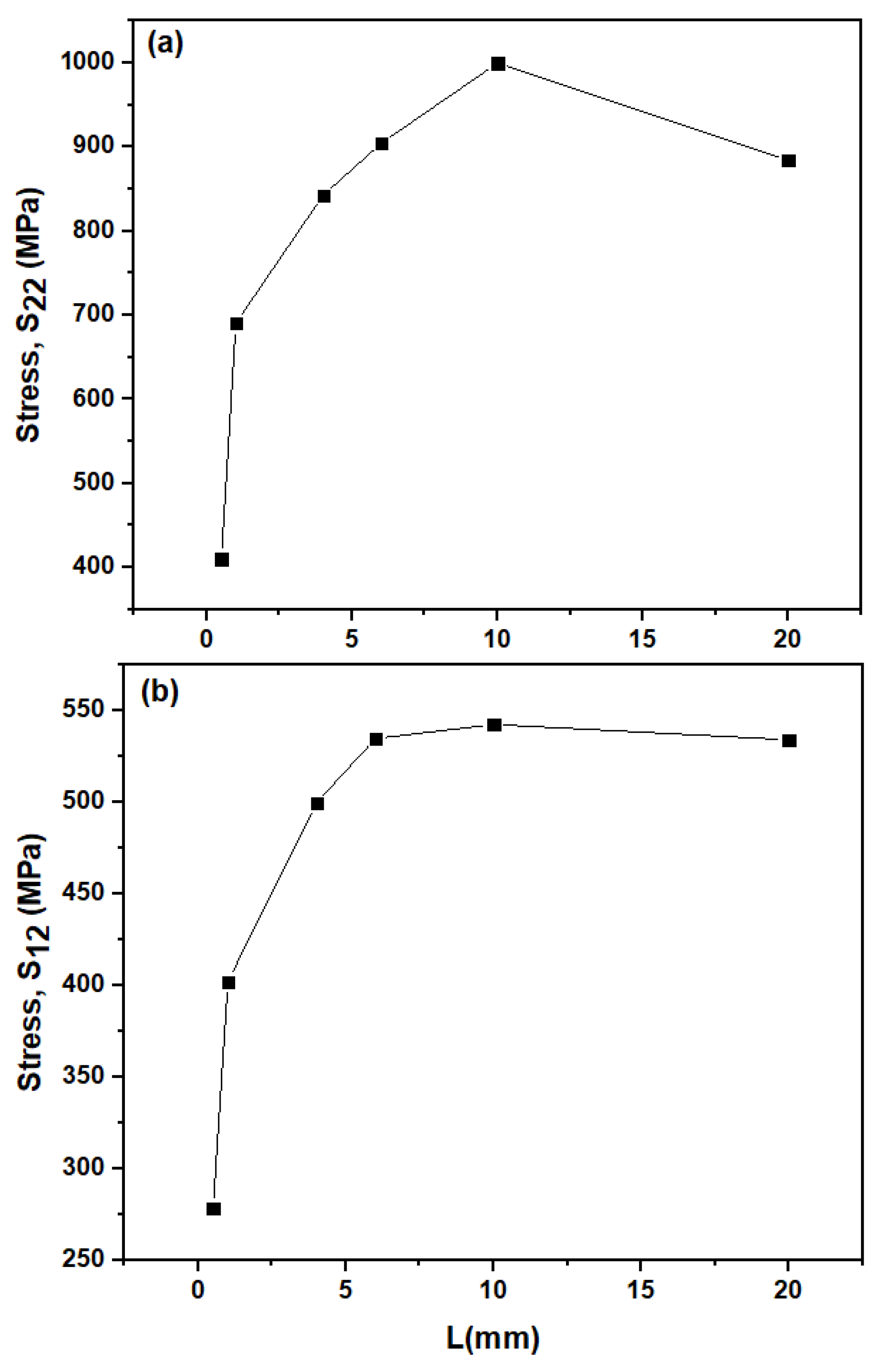
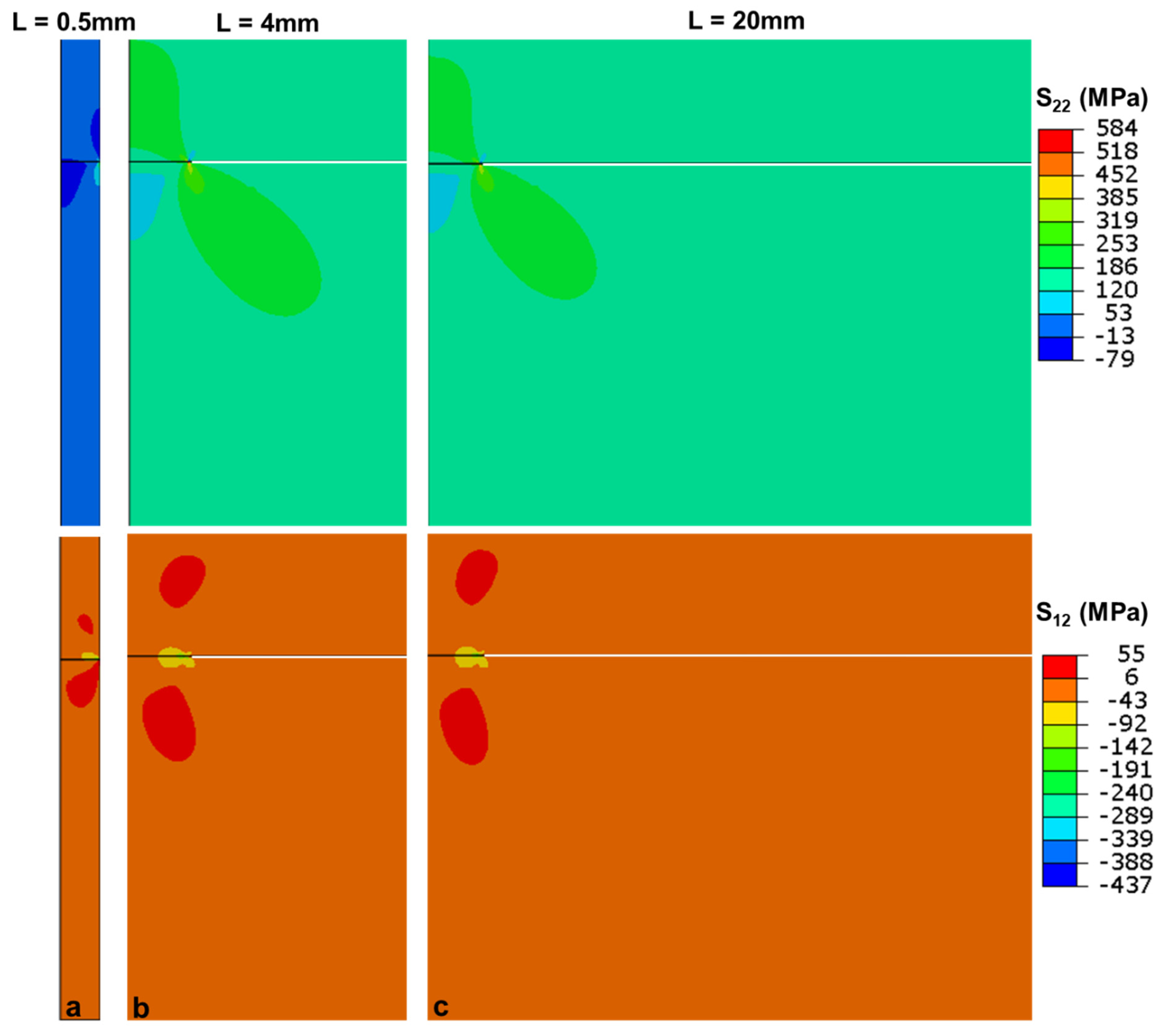
3.1. Influence of L on Stress Distribution in TC

In this study, a significant critical strain energy release rate (Gequivc) was first utilized to study the influence of the SVC (L) on the SERR of pre-crack. To achieve some significant data, the distribution of stress in the ceramic TC layer was primarily investigated at the pre-crack tip due to thermal mismatch strain between coatings and substrate, which caused the degradation of coating. Figure 3 represents the distribution of residual stresses of a thick thermal barrier coating with different SVC (L = 0.5, 1, 4, 6, 10 and 20 mm). It can be seen that the stresses (σ22 & σ12) have maximum values at the pre-crack tip. In fact, the residual stresses are very high (σ22 = 1520 MPa and σ12 = 850 MPa) when the SVC is 10 mm. The maximum stresses (σ22 & σ12) at the pre-crack tip gradually decrease from σ22 = 1520 MPa to σ22 = 585 MPa, and σ12 = 850 MPa to σ12 = 436 MPa, when the SVC decreases. The residual stresses (σ22 & σ12) are at minimum (σ22 = 585 MPa and σ12 = 436 MPa) at the pre-crack tip in the ceramic top-coat when the SVC is at its minimum, which is 0.5 mm. Our previous work [53] suggested that the maximum stresses at the pre-crack tip decreased as the vertical crack numbers in ceramic top-coat increased, and also decreased with an increase in their depth. This study further indicated that, when the SVC was controlled up to a suitable value, the SVC liberated the concentration of stress of thick TBCs. As a result, the strain tolerance improved, resulting in good resistance of thermal shock of thick TBCs with a reduction in the SVC.
Figure 4 represents the stress distribution along the path of the pre-crack for thick TBCs with different SVC. The horizontal line is shown in Figure 3, representing the path along which the pre-crack is propagated. In Figure 4a,b, the jump phenomenon of stresses (σ22 and σ12) at the pre-crack tip has appeared. The stresses (σ22 & σ12) at the position away from the pre-crack tip have a lower value. The value of stresses at the pre-crack tip is at minimum (σ22 = 410 MPa and σ12 = 278 MPa) when the SVC is minimum (L = 0.5 mm). The jump phenomenon of stresses at the pre-crack tip is increased with an increase in the SVC, and its value is at maximum σ22 = 999 MPa and σ12 = 542 MPa when “L” is 10 mm. It indicates that a larger SVC refers to smaller strain tolerance. This is why the thermal shock resistance of TBCs is weak for conventional coating structures without vertical cracks. It implies that the crack expands easily with a higher SVC in ceramic top-coat.
Figure 5 represents the graph of maximum stress distribution (σ22 & σ12) at the pre-crack tip of the ceramic TC layer as a function of the SVC (L). It can be seen easily from the graph that, when the spacing between two vertical cracks is increased, the stress σ22 is increased, as shown in Figure 5a. The value of stress σ22 reaches its maximum value when the SVC is 10 mm. After that, a little decrease in stress σ22 can be found with the increase of the SVC. The maximum stress σ12 at the pre-crack tip of the ceramic top-coat layer shows an increasing trend as the SVC increases up to 10 mm, as shown in Figure 5b. After that, σ12 shows a constant trend with further increases of the SVC up to 20 mm. It means that the SVC has a strong influence on the distribution of stress at the pre-crack tip in the ceramic top-coat. Additionally, Figure 5 shows that the crack growth depends upon the SVC. The crack is extended by increasing the SVC in thermal barrier coatings. As a result, the strain tolerance is reduced, resulting in a reduction in the thermal shock resistance of thick TBCs with a reduction in the SVC.

3.2. Effect of Driving Force on Crack Behavior

The values of SERR at the tip of the pre-crack must be assessed and compared with the fracture toughness of the top-coat, with the aim of simulating the delamination of coating and crack propagation [25]. The effect of the SVC on the SERR of the thermal barrier coating system analyzed in this section is stimulating, and suggests the possibility of enhancing the durability of TBCs by modifying the morphology of surface crack. In Figure 6, three regions (I, II, and III) can be seen to segregate the effect of the SVC on SERR. In region I, the SVC has a strong influence on the crack-driving force. In this case, the investigation of crack propagation and delamination of coating can be restricted and retarded. In the transition region (region II), the influence of the SVC slowly reduces as the delamination propagates. In the stable region (region III), the influence of crack spacing between two vertical cracks is unimportant and may be disregarded. It is considered that the crack-driving force of a coating does not depend upon the SVC, as the SVC is large enough-roughly ten times (L ≥ 20 mm) the ceramic top-coat thickness of the present study.
Figure 6 illustrates that, if the SVC is large enough, the SERR begins to be independent of the SVC. To explain it more clearly, a steady-state exists, and the crack energy released rate per unit increase very slow depending on the crack spacing between two vertical cracks. The concept of steady-state plays a significant role in investigating the unstable or/and stable propagation of coating delamination. Before the occurrence of crack propagation, the variation of the crack-driving force with the function of the SVC is plotted in Figure 6. Gt is the sum of (GI + GII), also known as the total SERR [57]. The surface crack spacing between two vertical cracks has a strong effect on the crack-driving force. When the surface crack spacing between two vertical cracks decreases, the steady-state of SERR decreases drastically, as seen in Figure 6. The SERR achieves a stable stage when the SVC is adequately large.

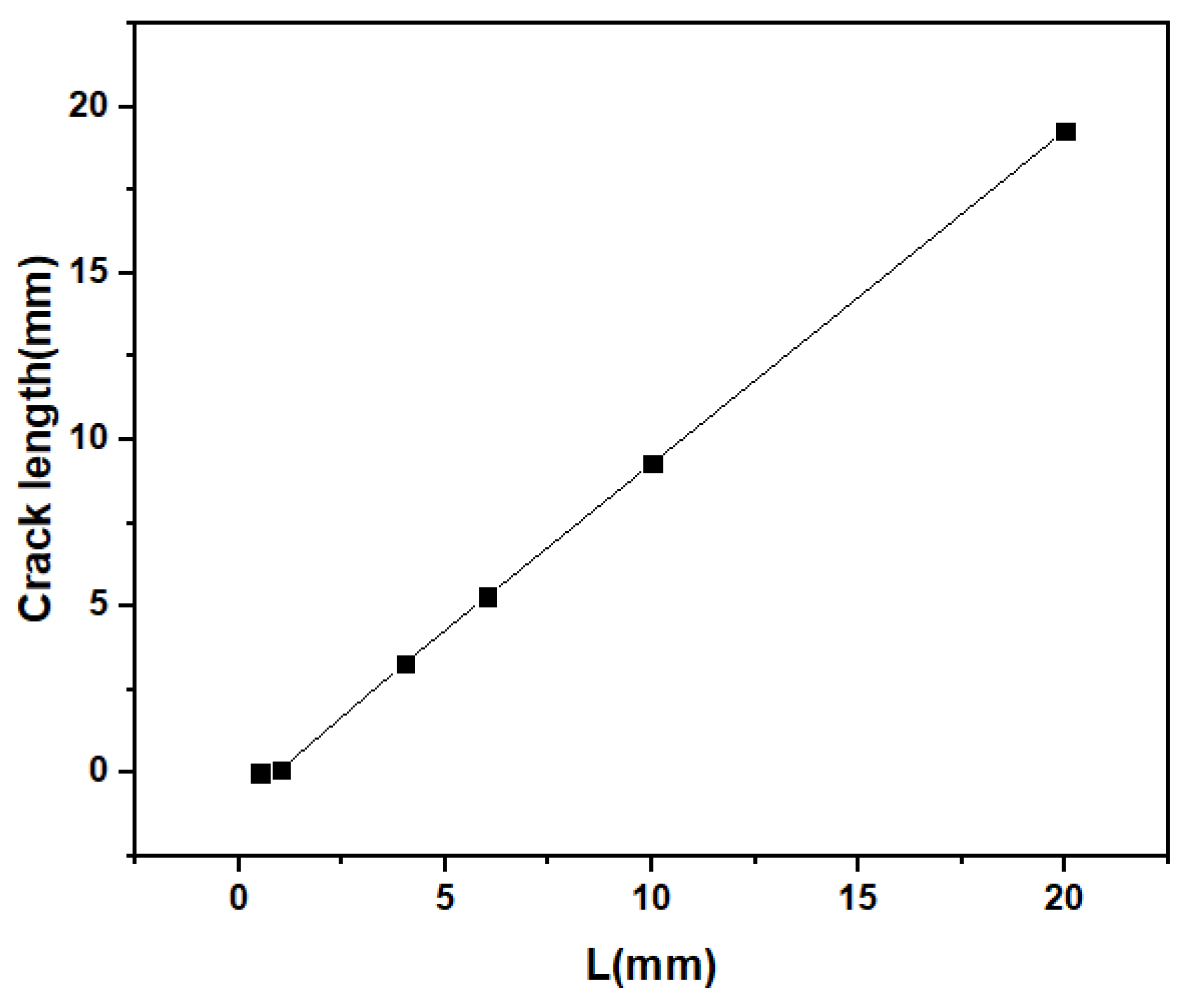
3.3. TC Crack Growth

The effects of the SVC on cracking behavior are studied in this section. Due to simulation results, large residual stresses are generated at the pre-crack tip in ceramic TC, and the BC and SUB layers may be considered as an entire part, defined as an equivalent substrate. The above-mentioned numerical results suggest that the SVC has a substantial influence on the cracking-driving force, which may be found whether or not crack growth extends into the ceramic top-coat. If the degradation of the coating follows the path of the pre-crack in TC, it presumes that the SVC will also be sorely affected by the propagation of a crack in the ceramic top-coat. Figure 7 shows the crack propagation in the ceramic top-coat with a variation in the SVC from 0.5 to 20 mm. For the case of region I in Figure 6, the crack-driving force is very small compared to the stable stage. As a result, the degradation of the coating does not occur if the release rate of the strain energy is lower than the fracture toughness of the coating. In Figure 7a, the crack is not propagated. In the case of the transition zone II, as shown in Figure 6, the crack grows along the crack propagation path in the ceramic top-coat. However, the propagation of the crack is stopped after a small distance, as shown in Figure 7b. In the case of stable zone III, as shown in Figure 6, the crack-driving force is stable in that region. The propagation of a crack in this region is obvious, as shown in Figure 7c. The propagation of crack, until a disastrous failure of TBCs, happens with the rising of the external loads. An enormous debonding may occur, and the most cohesive elements are disrupted in this case. These numerical results indicate that the delamination of the coating and crack growth in the ceramic top-coat can be reduced by decreasing the space between two vertical cracks, and can also retard the debonding of coating in TBCs. In addition, the life span of thermal barrier coatings can be improved by reducing the space between two vertical cracks.
Figure 8 represents the distribution of stresses σ22 and σ12 in ceramic top-coat along the root of crack propagation with respect to normalize distance at different SVC (L = 0.5, 1, 4, 6, 10, 20 mm). It is seen in Figure 8a that the stress σ22 is distributed along the crack path. The point where the jumped phenomenon of stress occurred is the crack tip, which was extended in the ceramic top-coat at different SVC. Here, it is seen that the jumping phenomenon of stress σ22 moved forward along the crack path as the SVC increased. Figure 8b represents the similar trend of stress (σ12) distribution along the crack path at different SVC. Here, it is also seen that the jumped phenomenon moved forward along the crack path as the SVC increased. These results indicate that the crack was propagated in the ceramic top-coat as the SVC increased, and reduced the life span of thermal barrier coatings, resulting in the failure of TBCs.
Figure 9 represents the variation of crack length in the ceramic top-coat with the SVC. The SVC has influenced the growth of the crack. At very small SVC, such as L = 0.5 mm, the crack is not extended. With the increase of the SVC, the growth of the crack is continuously increased. To understand the overall damage of coating, the normalized crack length is used, which is the total length of the crack and the model’s length ratio, i.e., a = a/L [57]. The crack is propagated rapidly into the model toward the left, due to a continuously increasing stress on the crack tip as the space between two vertical cracks increases. The spallation of the coating is due to the coalescence of the crack, and this coalescence of the crack is responsible for the TBC’s failure. The crack growth can be decreased by decreasing the SVC, and may extend the lifetime of TBCs.
TBCs with thicker coatings have greater thermal insulation. Therefore, thick TBCs have various applications in engineering—for example, they are essential for radar absorption [55,62]. However, in our previous study [53], thick TBCs often have a greater crack-driving force and stress due to the thermal mismatch strain between coating and substrate at the tip of the crack. This mean that the thicker TC is easily spalled or cracked. That is why the thicker TBCs have short life spans, and so are not suited to coating applications. In our previous studies, a significant influence in decreasing the crack-driving force was inserting vertical cracks in ceramic TC. Based on our examination, the space between two vertical cracks has a significant effect on decreasing the crack-driving force. Therefore, to increase the crack resistance of thick TC, reducing the SVC would be a possible solution. Another problem is how to insert vertical cracks in APS-TC. When the dense vertical cracked (DVC) structure method is used, the structure has to have a greater density than conventional TBC. As a result, the thermal conductivity should be high, and the thermal insulation is reduced [26,63]. In future work, it is essential to develop new ways to insert vertical cracks in porous APS-TC. In this way, the function and life span can be concurrently increased.

4. Conclusions

In the present study, the influence of the SVC on the cracking of plasma sprayed TBCs has been investigated. A finite element model was used for a comprehensive investigation of cracking behavior and coalescence in the top-coat. Additionally, the influence of the SVC on SERRs was also investigated to understand crack resistance behavior. In conclusion, the SVC is an essential parameter to indicate the degradation and initiation of crack propagation in the ceramic top-coat. In the ceramic top-coat, the concentration of maximum residual stresses are mainly at the pre-crack tip, which may result in a phenomenon by which a crack nucleates in this region and can cause the propagation of a crack in the ceramic top-coat. These stresses are continuously increasing as the SVC increases, up to a specific distance. The failure mechanism of the coating was also identified by the crack-driving force. The crack-driving force is enhanced with the increase in the SVC, and three different regions were identified. In region I, the SERRs are sharply decreased for a very small value of SVC. In this state, the crack propagation can be delayed. In region II, the SVC is moderate. In this case, the crack is propagated and then stopped after a small distance of propagation. Analysis of this brings us to a critical value of SVC. Region III appears for a sufficiently large value of SVC. In this case, SERRs reach a stable state, where the influence of the SVC is insignificant, and the propagation of the crack is due to the external load. Based on these results, we can conclude that the crack growth can be reduced by decreasing the value of SVC, which may improve the strain tolerance to obtain durable TBCs. Additionally, the function and life span of TBCs can be concurrently increased.

Author Contributions

Conceptualization, G.M.; methodology, G.M.; software, G.M. and A.T.; validation, G.-R.L.; formal analysis, G.M. and G.-R.L.; investigation, G.M.; resources, G.-R.L.; data curation, G.-R.L. and T.X.; writing-original draft preparation, G.M.; writing-review and editing, G.M., T.X., G.-R.L., G.-J.Y., S.H., M.R. and A.T.; visualization, S.H.; supervision, G.-R.L., T.X. and G.-J.Y.; project administration, G.-R.L.; funding acquisition, G.-R.L. and G.-J.Y. All authors have read and agreed to the published version of the manuscript.

Funding

The authors gratefully acknowledge the National Natural Science Foundation of China (Grant number 51801148); the Natural Science Foundation of Shaanxi Province (grant number 2019JQ-165); the Young Talent fund of University Association for Science and Technology in Shaanxi, China (grant number 20190403).

Institutional Review Board Statement

Not applicable.

Informed Consent Statement

Not applicable.

Conflicts of Interest

The authors declare no conflict of interest.

References

  1. Padture, N.P. Advanced structural ceramics in aerospace propulsion. Nat. Mater. 2016, 15, 804–809. [Google Scholar] [CrossRef]
  2. s40145-020-0449-7.pdf. Available online: https://link.springer.com/content/pdf/10.1007/s40145-020-0449-7.pdf (accessed on 15 April 2021).
  3. Li, F.; Zhou, L.; Liu, J.-X.; Liang, Y.; Zhang, G.-J. High-entropy pyrochlores with low thermal conductivity for thermal barrier coating materials. J. Adv. Ceram. 2019, 8, 576–582. [Google Scholar] [CrossRef] [Green Version]
  4. Yang, L.; Chen, M.; Wang, J.; Qiao, Y.; Guo, P.; Zhu, S.; Wang, F. Microstructure and composition evolution of a single-crystal superalloy caused by elements interdiffusion with an overlay NiCrAlY coating on oxidation. J. Mater. Sci. Technol. 2020, 45, 49–58. [Google Scholar] [CrossRef]
  5. Guo, L.; Xin, H.; Li, Y.; Yu, Y.; Yan, Z.; Hu, C.; Ye, F. Self-crystallization characteristics of calcium-magnesium-alumina- silicate (CMAS) glass under simulated conditions for thermal barrier coating applications. J. Eur. Ceram. Soc. 2020, 40, 5683–5691. [Google Scholar] [CrossRef]
  6. Clarke, D.R.; Oechsner, M.; Padture, N.P. Thermal-barrier coatings for more efficient gas-turbine engines. MRS Bull. 2012, 37, 891–898. [Google Scholar] [CrossRef] [Green Version]
  7. Chen, H.; Zhao, Z.; Xiang, H.; Dai, F.-Z.; Xu, W.; Sun, K.; Liu, J.; Zhou, Y. High entropy (Y0.2Yb0.2Lu0.2Eu0.2Er0.2)3Al5O12: A novel high temperature stable thermal barrier material. J. Mater. Sci. Technol. 2020, 48, 57–62. [Google Scholar] [CrossRef]
  8. Cao, X.; Vassen, R.; Fischer, W.; Tietz, F.; Jungen, W.; Stöver, D. Lanthanum-cerium oxide as a thermal barrier-coating material for high-temperature applications. Adv. Mater. 2003, 15, 1438–1442. [Google Scholar] [CrossRef]
  9. Cao, X.Q.; Vassen, R.; Tietz, F.; Stoever, D. New double-ceramic-layer thermal barrier coatings based on zirconia–rare earth composite oxides. J. Eur. Ceram. Soc. 2006, 26, 247–251. [Google Scholar] [CrossRef]
  10. Cao, X.; Li, J.; Zhong, X.; Zhang, J.; Zhang, Y.; Vassen, R.; Stoever, D. La2(Zr0.7Ce0.3)2O7—A new oxide ceramic material with high sintering-resistance. Mater. Lett. 2008, 62, 2667–2669. [Google Scholar] [CrossRef]
  11. Wu, P.; Hu, M.Y.; Chong, X.Y.; Feng, J. The glass-like thermal conductivity in ZrO2–Dy3TaO7 ceramic for promising thermal barrier coating application. Appl. Phys. Lett. 2018, 112, 131903. [Google Scholar] [CrossRef]
  12. Liu, B.; Liu, Y.; Zhu, C.; Xiang, H.; Chen, H.; Sun, L.; Gao, Y.; Zhou, Y. Advances on strategies for searching for next generation thermal barrier coating materials. J. Mater. Sci. Technol. 2019, 35, 833–851. [Google Scholar] [CrossRef]
  13. Cao, X.Q.; Zhang, Y.F.; Zhang, J.F.; Zhong, X.H.; Wang, Y.; Ma, H.M.; Xu, Z.H.; He, L.M.; Lu, F. Failure of the plasma-sprayed coating of lanthanum hexaluminate. J. Eur. Ceram. Soc. 2008, 28, 1979–1986. [Google Scholar] [CrossRef]
  14. Li, D.; Jiang, P.; Gao, R.; Sun, F.; Jin, X.; Fan, X. Experimental and numerical investigation on the thermal and mechanical behaviours of thermal barrier coatings exposed to CMAS corrosion. J. Adv. Ceram. 2021. [Google Scholar] [CrossRef]
  15. Guo, L.; Xin, H.; Zhang, Z.; Zhang, X.; Ye, F. Microstructure modification of Y2O3 stabilized ZrO2 thermal barrier coatings by laser glazing and the effects on the hot corrosion resistance. J. Adv. Ceram. 2020, 9, 232–242. [Google Scholar] [CrossRef] [Green Version]
  16. Fan, W.; Bai, Y. Review of suspension and solution precursor plasma sprayed thermal barrier coatings. Ceram. Int. 2016, 42, 14299–14312. [Google Scholar] [CrossRef]
  17. Morelli, S.; Testa, V.; Bolelli, G.; Ligabue, O.; Molinari, E.; Antolotti, N.; Lusvarghi, L. CMAS corrosion of YSZ thermal barrier coatings obtained by different thermal spray processes. J. Eur. Ceram. Soc. 2020, 40, 4084–4100. [Google Scholar] [CrossRef]
  18. Shakhova, I.; Mironov, E.; Azarmi, F.; Safonov, A. Thermo-electrical properties of the alumina coatings deposited by different thermal spraying technologies. Ceram. Int. 2017, 43, 15392–15401. [Google Scholar] [CrossRef]
  19. Liu, M.-J.; Zhang, K.-J.; Zhang, Q.; Zhang, M.; Yang, G.-J.; Li, C.-X.; Li, C.-J. Thermodynamic conditions for cluster formation in supersaturated boundary layer during plasma spray-physical vapor deposition. Appl. Surf. Sci. 2019, 471, 950–959. [Google Scholar] [CrossRef]
  20. Vaßen, R.; Bakan, E.; Mack, D.; Schwartz-Lückge, S.; Sebold, D.; Sohn, Y.J.; Zhou, D.; Guillon, O. Performance of YSZ and Gd2Zr2O7/YSZ double layer thermal barrier coatings in burner rig tests. J. Eur. Ceram. Soc. 2020, 40, 480–490. [Google Scholar] [CrossRef]
  21. Zhang, X.; Zhou, K.; Xu, W.; Song, J.; Deng, C.; Liu, M. Reaction mechanism and thermal insulation property of al-deposited 7ysz thermal barrier coating. J. Mater. Sci. Technol. 2015, 31, 1006–1010. [Google Scholar] [CrossRef]
  22. Wang, L.; Liu, C.G.; Zhong, X.H.; Zhao, Y.X.; Zhao, H.Y.; Yang, J.S.; Tao, S.Y.; Wang, Y. Investigation of crack propagation behavior of atmospheric plasma-sprayed thermal barrier coatings under uniaxial tension using the acoustic emission technique. J. Therm. Spray Tech. 2015, 24, 296–308. [Google Scholar] [CrossRef]
  23. Gupta, M.; Li, X.-H.; Markocsan, N.; Kjellman, B. Design of high lifetime suspension plasma sprayed thermal barrier coatings. J. Eur. Ceram. Soc. 2020, 40, 768–779. [Google Scholar] [CrossRef]
  24. Lashmi, P.G.; Ananthapadmanabhan, P.V.; Unnikrishnan, G.; Aruna, S.T. Present status and future prospects of plasma sprayed multilayered thermal barrier coating systems. J. Eur. Ceram. Soc. 2020, 40, 2731–2745. [Google Scholar] [CrossRef]
  25. Wei, Z.-Y.; Cai, H.-N.; Li, C.-J. Comprehensive dynamic failure mechanism of thermal barrier coatings based on a novel crack propagation and TGO growth coupling model. Ceram. Int. 2018, 44, 22556–22566. [Google Scholar] [CrossRef]
  26. Cheng, B.; Yang, N.; Zhang, Q.; Zhang, M.; Zhang, Y.-M.; Chen, L.; Yang, G.-J.; Li, C.-X.; Li, C.-J. Sintering induced the failure behavior of dense vertically crack and lamellar structured TBCs with equivalent thermal insulation performance. Ceram. Int. 2017, 43, 15459–15465. [Google Scholar] [CrossRef]
  27. Wang, L.; Li, D.C.; Yang, J.S.; Shao, F.; Zhong, X.H.; Zhao, H.Y.; Yang, K.; Tao, S.Y.; Wang, Y. Modeling of thermal properties and failure of thermal barrier coatings with the use of finite element methods: A review. J. Eur. Ceram. Soc. 2016, 36, 1313–1331. [Google Scholar] [CrossRef]
  28. Mehboob, G.; Liu, M.-J.; Xu, T.; Hussain, S.; Mehboob, G.; Tahir, A. A review on failure mechanism of thermal barrier coatings and strategies to extend their lifetime. Ceram. Int. 2020, 46, 8497–8521. [Google Scholar] [CrossRef]
  29. Dong, T.-S.; Wang, R.; Di, Y.-L.; Wang, H.-D.; Li, G.-L.; Fu, B.-G. Mechanism of high temperature oxidation resistance improvement of double-layer thermal barrier coatings (TBCs) by La. Ceram. Int. 2019, 45, 9126–9135. [Google Scholar] [CrossRef]
  30. Abubakar, A.A.; Arif, A.F.M.; Al-Athel, K.S.; Akhtar, S.S.; Mostaghimi, J. Modeling residual stress development in thermal spray coatings: Current status and way forward. J. Therm. Spray Tech. 2017, 26, 1115–1145. [Google Scholar] [CrossRef]
  31. Chen, L.; Yang, G.-J. Epitaxial growth and cracking of highly tough 7YSZ splats by thermal spray technology. J. Adv. Ceram. 2018, 7, 17–29. [Google Scholar] [CrossRef] [Green Version]
  32. Li, G.; Yang, G. Understanding of degradation-resistant behavior of nanostructured thermal barrier coatings with bimodal structure. J. Mater. Sci. Technol. 2019, 35, 231–238. [Google Scholar] [CrossRef]
  33. Mao, W.; Wang, Y.; Shi, J.; Huang, H.; Wang, Y.; Lv, L.; Yang, H.; Zou, C.; Dai, C.; Zhu, X.; et al. Bending fracture behavior of freestanding (Gd0.9Yb0.1)2Zr2O7 coatings by using digital image correlation and FEM simulation with 3D geometrical reconstruction. J. Adv. Ceram. 2019, 8, 564–575. [Google Scholar] [CrossRef] [Green Version]
  34. Benini, E. Progress in Gas Turbine Performance; BoD-Books on Demand: Norderstedt, Germany, 2013. [Google Scholar]
  35. Chen, L.; Hu, M.; Guo, J.; Chong, X.; Feng, J. Mechanical and thermal properties of RETaO4 (RE = Yb, Lu, Sc) ceramics with monoclinic-prime phase. J. Mater. Sci. Technol. 2020, 52, 20–28. [Google Scholar] [CrossRef]
  36. Li, J.; Wei, L.; He, J.; Chen, H.; Guo, H. The role of Re in improving the oxidation-resistance of a Re modified PtAl coating on Mo-Rich single crystal superalloy. J. Mater. Sci. Technol. 2020, 58, 63–72. [Google Scholar] [CrossRef]
  37. Yang, Z.; Zhang, P.; Pan, W.; Han, Y.; Huang, M.; Chen, H.; Gong, Q.; Wan, C. Thermal and oxygen transport properties of complex pyrochlore RE2 In TaO7 for thermal barrier coating applications. J. Eur. Ceram. Soc. 2020, 40, 6229–6235. [Google Scholar] [CrossRef]
  38. Al Zoubi, W.; Kamil, M.P.; Fatimah, S.; Nashrah, N.; Ko, Y.G. Recent advances in hybrid organic-inorganic materials with spatial architecture for state-of-the-art applications. Prog. Mater. Sci. 2020, 112, 100663. [Google Scholar] [CrossRef]
  39. Al Zoubi, W.; Ko, Y.G. Chemical stability of synergistic inorganic materials for enhancing electrochemical performance. Compos. Sci. Technol. 2020, 199, 108383. [Google Scholar] [CrossRef]
  40. Xing, Q.; Shu-ai, Z.; Xiaofeng, G.; Renping, Y.; Yi, L.; Hui, T.; Shicheng, W.; Yongchao, F.; Hao, W.; Shengjian, X. Microstructure and thermal shock resistance of Nd2O3-doped YSZ-based thermal barrier coatings. Ceram. Int. 2020, 46, 26841–26853. [Google Scholar] [CrossRef]
  41. Izadinia, M.; Soltani, R.; Sohi, M.H. Effect of segmented cracks on TGO growth and life of thick thermal barrier coating under isothermal oxidation conditions. Ceram. Int. 2020, 46, 7475–7481. [Google Scholar] [CrossRef]
  42. Lv, B.; Jin, X.; Cao, J.; Xu, B.; Wang, Y.; Fang, D. Advances in numerical modeling of environmental barrier coating systems for gas turbines. J. Eur. Ceram. Soc. 2020, 40, 3363–3379. [Google Scholar] [CrossRef]
  43. Zhu, Y.; Yan, B.; Cai, D.; Wu, K.; Zhang, X. Structural parameter study on stress intensity factors of interfacial crack in thermal barrier coatings. Ceram. Int. 2021, 47, 14354–14365. [Google Scholar] [CrossRef]
  44. Abdul-Baqi, A.; van der Giessen, E. Indentation-induced interface delamination of a strong film on a ductile substrate. Thin Solid Film. 2001, 381, 143–154. [Google Scholar] [CrossRef] [Green Version]
  45. Rezaei, S.; Wulfinghoff, S.; Reese, S. Prediction of fracture and damage in micro/nano coating systems using cohesive zone elements. Int. J. Solids Struct. 2017, 121, 62–74. [Google Scholar] [CrossRef]
  46. Holmberg, K.; Laukkanen, A.; Ronkainen, H.; Wallin, K. Finite element analysis of coating adhesion failure in pre-existing crack field. Tribol. Mater. Surf. Interfaces 2013, 7, 42–51. [Google Scholar] [CrossRef]
  47. Wei, Z.-Y.; Cai, H.-N.; Meng, G.-H.; Tahir, A.; Zhang, W.-W. An innovative model coupling TGO growth and crack propagation for the failure assessment of lamellar structured thermal barrier coatings. Ceram. Int. 2020, 46, 1532–1544. [Google Scholar] [CrossRef]
  48. Rybicki, E.F.; Kanninen, M.F. A finite element calculation of stress intensity factors by a modified crack closure integral. Eng. Fract. Mech. 1977, 9, 931–938. [Google Scholar] [CrossRef]
  49. Ming-Che, L.; Erdogan, F. Stress intensity factors in two bonded elastic layers containing cracks perpendicular to and on the interface—I. Analysis. Eng. Fract. Mech. 1983, 18, 491–506. [Google Scholar] [CrossRef]
  50. Wu, C.-W.; Chen, G.-N.; Zhang, K.; Luo, G.-X.; Liang, N.-G. The effect of periodic segmentation cracks on the interfacial debonding: Study on interfacial stresses. Surf. Coat. Technol. 2006, 201, 287–291. [Google Scholar] [CrossRef] [Green Version]
  51. Zhou, B.; Kokini, K. Effect of pre-existing surface crack morphology on the interfacial thermal fracture of thermal barrier coatings: A numerical study. Mater. Sci. Eng. A 2003, 348, 271–279. [Google Scholar] [CrossRef]
  52. Zhou, B.; Kokini, K. Effect of surface pre-crack morphology on the fracture of thermal barrier coatings under thermal shock. Acta Mater. 2004, 52, 4189–4197. [Google Scholar] [CrossRef]
  53. Mehboob, G.; Xu, T.; Li, G.-R.; Hussain, S.; Mehboob, G.; Tahir, A. Strain-Induced Cracking Behavior of Coating/Substrate Systems and Strain Tolerant Design for Thick Coatings. Coatings 2020, 10, 1066. [Google Scholar] [CrossRef]
  54. Lee, D.H.; Lee, K.S.; Kim, T.W.; Kim, C. Hertzian stress analysis and characterization of thermal barrier coatings containing unidirectional vertical cracks. Ceram. Int. 2019, 45, 21348–21358. [Google Scholar] [CrossRef]
  55. Wang, L.; Zhong, X.H.; Shao, F.; Ni, J.X.; Yang, J.S.; Tao, S.Y.; Wang, Y. What is the suitable segmentation crack density for atmospheric plasma sprayed thick thermal barrier coatings with the improved thermal shock resistance? Appl. Surf. Sci. 2018, 431, 101–111. [Google Scholar] [CrossRef]
  56. Fan, X.L.; Xu, R.; Zhang, W.X.; Wang, T.J. Effect of periodic surface cracks on the interfacial fracture of thermal barrier coating system. Appl. Surf. Sci. 2012, 258, 9816–9823. [Google Scholar] [CrossRef]
  57. Wei, Z.-Y.; Cai, H.-N.; Feng, R.-X.; Su, J.-Y. Dynamic crack growth mechanism and lifetime assessment in plasma sprayed thermal barrier system upon temperature cycling. Ceram. Int. 2019, 45, 14896–14907. [Google Scholar] [CrossRef]
  58. Rabiei, A.; Evans, A.G. Failure mechanisms associated with the thermally grown oxide in plasma-sprayed thermal barrier coatings. Acta Mater. 2000, 48, 3963–3976. [Google Scholar] [CrossRef]
  59. Wang, L.; Yang, J.S.; Ni, J.X.; Liu, C.G.; Zhong, X.H.; Shao, F.; Zhao, H.Y.; Tao, S.Y.; Wang, Y. Influence of cracks in APS-TBCs on stress around TGO during thermal cycling: A numerical simulation study. Surf. Coat. Technol. 2016, 285, 98–112. [Google Scholar] [CrossRef]
  60. AD0099305.pdf. Available online: https://apps.dtic.mil/sti/pdfs/AD0099305.pdf (accessed on 10 February 2021).
  61. Zhu, W.; Zhang, Z.B.; Yang, L.; Zhou, Y.C.; Wei, Y.G. Spallation of thermal barrier coatings with real thermally grown oxide morphology under thermal stress. Mater. Des. 2018, 146, 180–193. [Google Scholar] [CrossRef]
  62. Lu, S.; Huang, J.; Song, L.; Yi, M. A study on zoning coating method of absorbing materials for stealth aircraft. Optik 2020, 208, 163912. [Google Scholar] [CrossRef]
  63. Madhwal, M.; Jordan, E.H.; Gell, M. Failure mechanisms of dense vertically-cracked thermal barrier coatings. Mater. Sci. Eng. A 2004, 384, 151–161. [Google Scholar] [CrossRef]
Figure 1. Model of TBCs with vertical cracks in TC: (a) the model geometry, (b) overall model mesh and boundary conditions, and (c) the dense mesh close to the TC/BC interface.
Coatings 11 00720 g001
Figure 2. Schematic representation of the VCCT reasonable for the quadrilateral element with four nodes.
Coatings 11 00720 g002
Figure 3. The stress distribution (S22 and S12) at crack tip under different SVC.
Coatings 11 00720 g003
Figure 4. The stress distribution (a) S22 and (b) S12 at the crack tip under different SVC along the pre-crack path.
Coatings 11 00720 g004
Figure 5. Stress distribution (a) S22 and (b) S12 at the pre-crack tip.
Coatings 11 00720 g005
Figure 6. Influence of the SVC on cracking-driving force.
Coatings 11 00720 g006
Figure 7. The crack propagation behavior for different cases of the SVC: (a) L = 0.5 mm, (b) L = 4 mm and (c) L = 20 mm.
Coatings 11 00720 g007
Figure 8. The crack behavior under different L due to stress distribution (a) S22 and (b) S12.
Coatings 11 00720 g008
Figure 9. Crack growth under different crack spacing between two vertical cracks.
Coatings 11 00720 g009
Table 1. Mechanical and thermal properties for all layers material [56,57,58,59].
PropertiesSUBBCTC
Young’s modulus E (GPa)21020050
Poisson ratio v0.30.30.15
TEC α (10−6/K)913.614.8
Publisher’s Note: MDPI stays neutral with regard to jurisdictional claims in published maps and institutional affiliations.

