
Characterization of Electroless Nickel–Boron Deposit from Optimized Stabilizer-Free Bath


Abstract
:1. Introduction
2. Materials and Methods
2.1. Substrate Preparation
2.2. Electroless Nickel Baths
2.3. Characterization
3. Results and Discussion
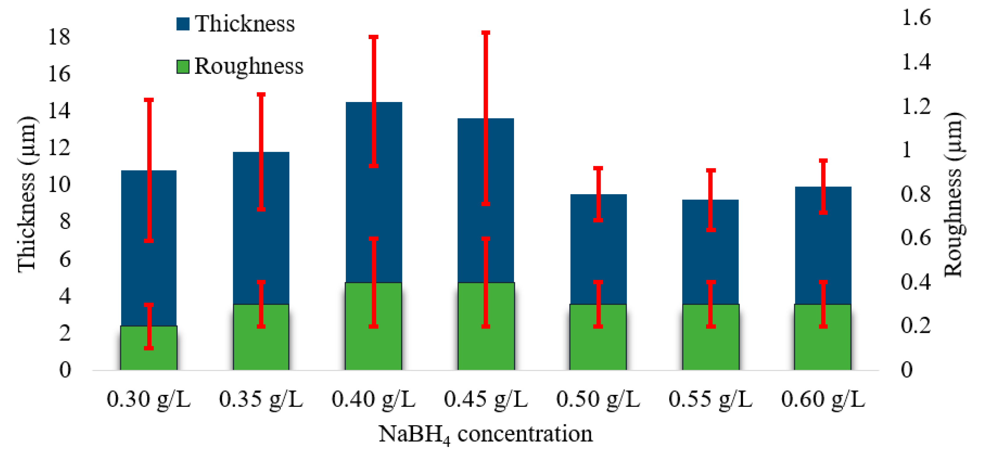
3.1. The Impact of NaBH4 Concentration on Plating Rate and Roughness
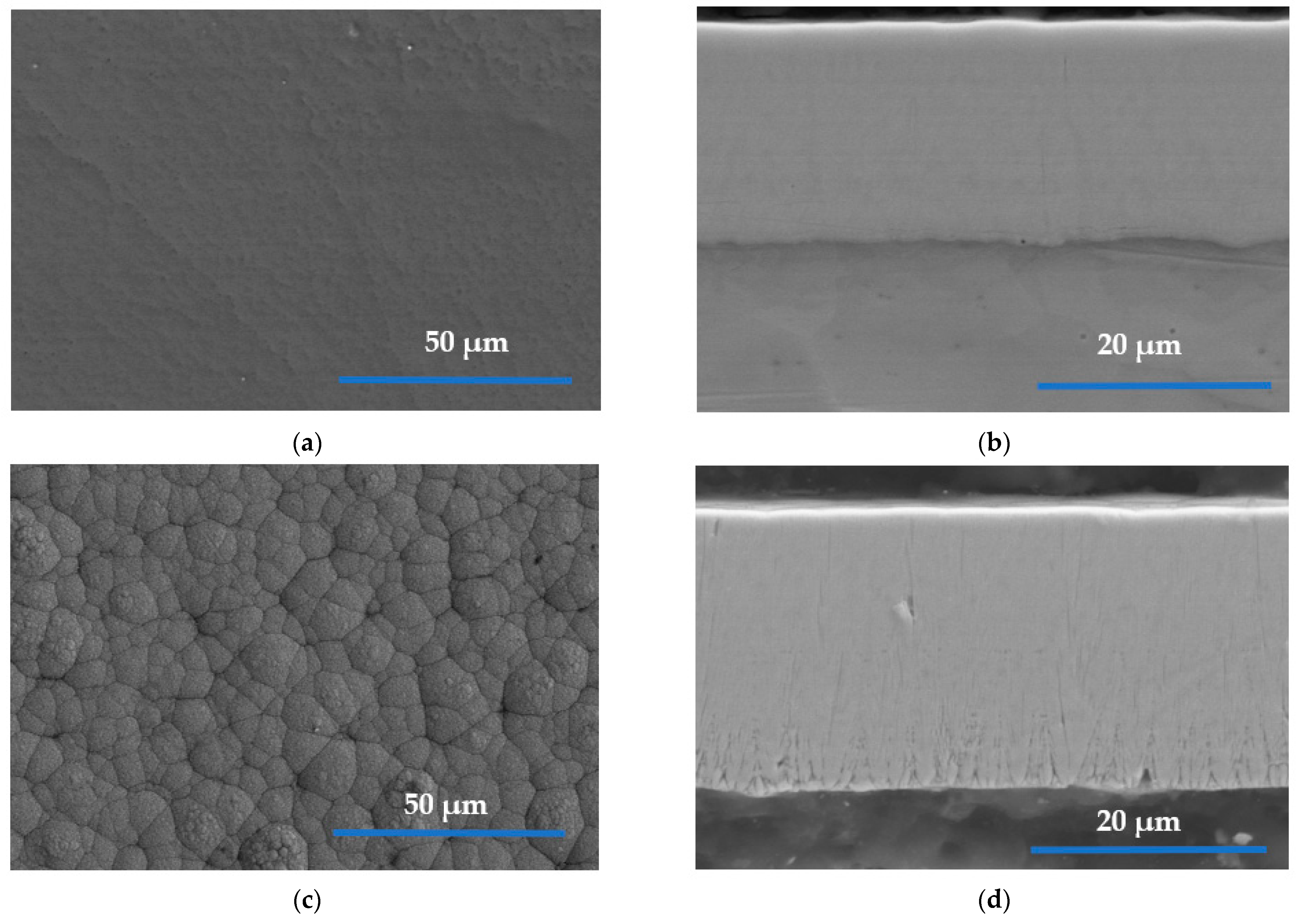
3.2. Morphology of the ENB Coatings
3.3. Profile Chemistry
3.4. Roughness
3.5. Hardness
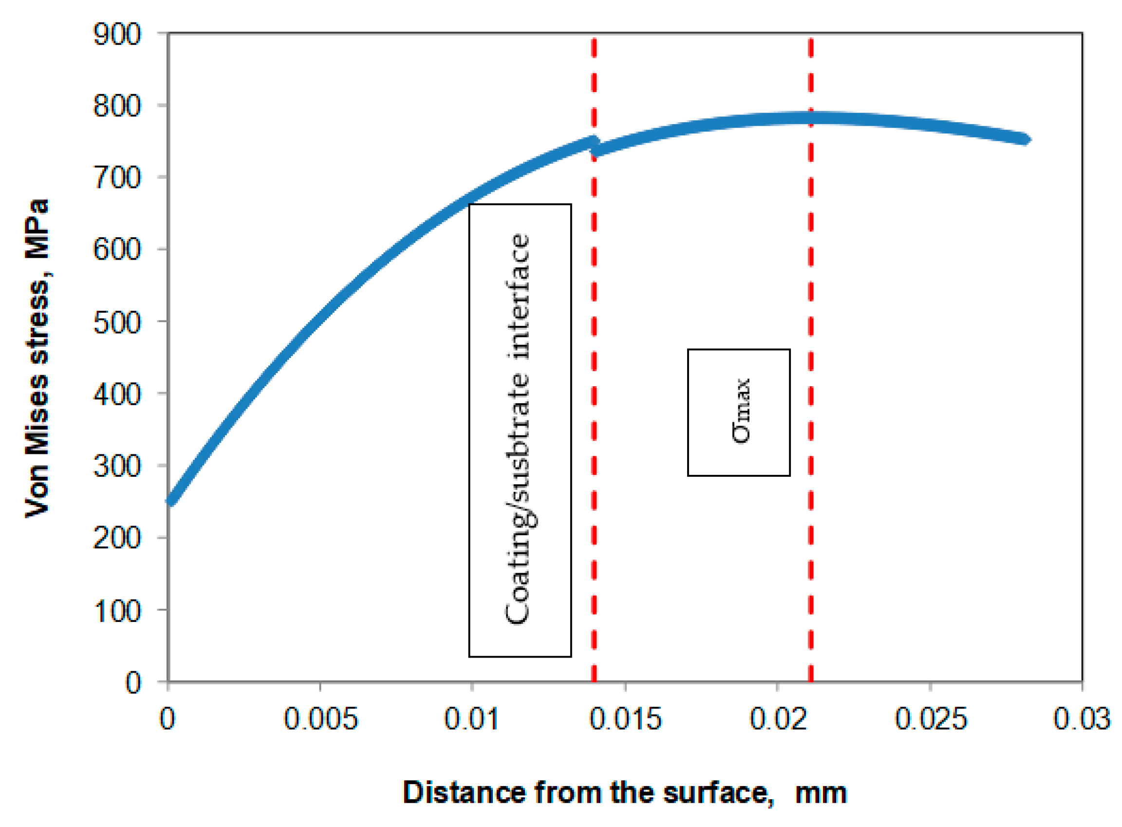
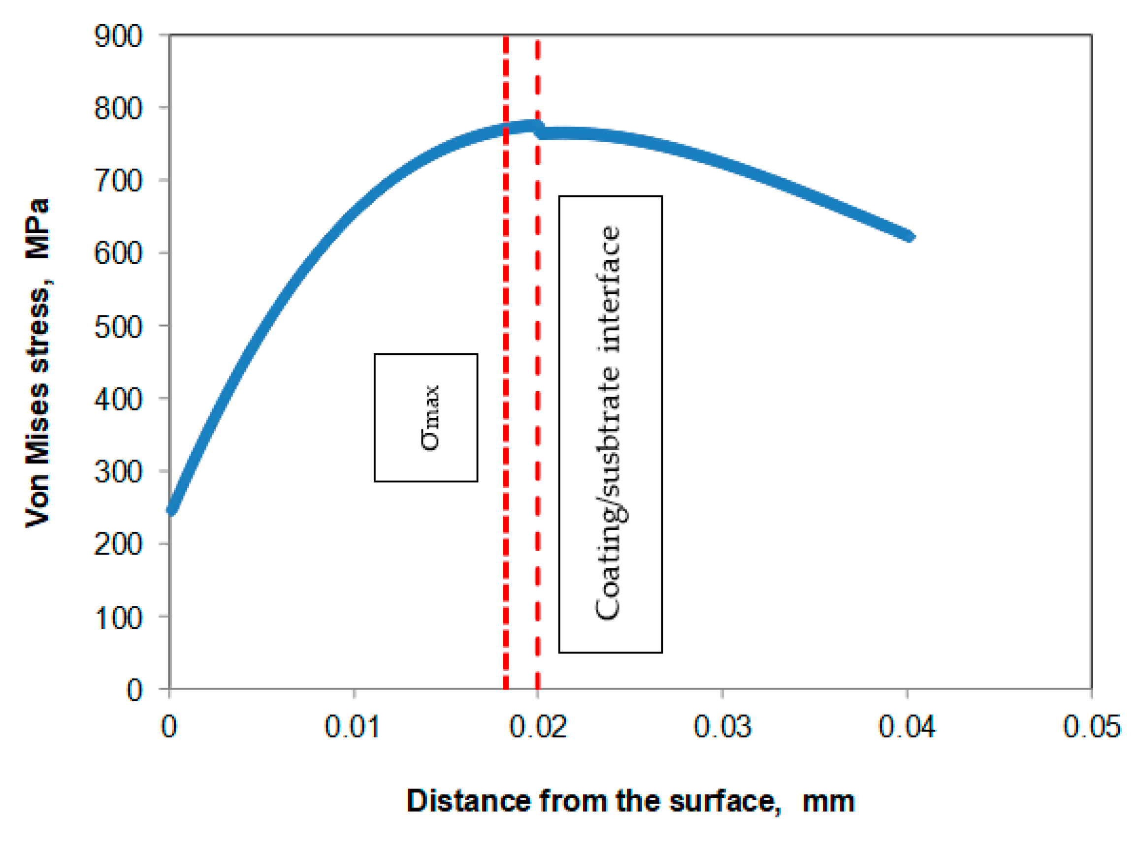
3.6. Scratch Test
3.7. Ball-on-Disc Wear Test
3.8. Corrosion Tests
4. Conclusions
- The reducing agent content of an electroless nickel–boron plating bath exempt of stabilizer was optimized;
- The ENB deposit was produced in a bath exempt of lead whose application and use have been restricted. Therefore, this deposit can be used as an alternative to conventional electroless nickel plating for several practical applications;
- The productivity of the process in the new bath increased from 10 to 14.5 µm/h;
- The difference in wear behavior exhibited by both deposits was due to the variation in the coatings thickness and the lack of support of the steel substrate and not a consequence of their intrinsic properties;
- The ENB deposit presented a distinct morphology from usual electroless nickel–boron coatings: the new deposits do not present a cauliflower-like structure nor a columnar structure. On the contrary, their surface morphology was featureless and uniform;
- The chemical composition of the new coating was also significantly different from standard electroless nickel–boron. First, it did not contain lead, which is highly favorable from the environmental point of view. Second, the boron content was lower than in conventional nickel–boron or previously reported ENB deposits. The new deposits had approximately 4 wt.% B and 96 wt.% Ni;
- The new deposits present high hardness, which was close to or better than the conventional electroless nickel–boron deposit. This result was confirmed by three different tests: micro-Vickers, micro-Knoop, and nanoindentation;
- One of the most promising results was corrosion resistance, which improved due to the modification in the surface and cross-sectional morphology and the change in the chemical composition of the coating;
Author Contributions
Funding
Institutional Review Board Statement
Informed Consent Statement
Data Availability Statement
Acknowledgments
Conflicts of Interest
References
- Riedel, W. Electroless Nickel Plating; Finishing Publications: London, UK, 1989; ISBN 0-904477-12-6. [Google Scholar]
- Vitry, V. Electroless Nickel-Boron Deposits: Synthesis, Formation and Characterization; Effect of Heat Treatments; Analytical Modeling of the Structural State. Ph.D. Thesis, University of Mons, Mons, Belgium, 2009. [Google Scholar]
- Delaunois, F.; Vitry, V.; Bonin, L. Electroless Nickel Plating, Fundamentals to Applications; Taylor&Francis Group: Abingdon-on-Thames, UK, 2019; ISBN 13:978-1-138-60580-0. [Google Scholar]
- Bonin, L. Replacement of Lead Stabilizer in Electroless NiB Baths: New Composition of Green Baths with Properties Characterization. Ph.D. Thesis, University of Mons, Mons, Belgium, 2018. [Google Scholar]
- Srinivasan, K.N.; Meenakshi, R.; Santhi, A.; Thangavelu, P.R.; John, S. Studies on development of electroless Ni-B bath for corrosion resistance and wear resistance applications. Surf. Eng. 2010, 26, 153–158. [Google Scholar] [CrossRef]
- Venkatakrishnan, P.G.; Mohamed Nazirudeen, S.S.; Sankara Narayanan, T.S.N. Electroless Ni-B-P ternary alloy coatings: Preparation and evaluation of characteristic properties. Eur. J. Sci. Res. 2012, 82, 506–514. [Google Scholar]
- Zhang, B. Amorphous and Nano Alloys Electroless Depositions; Elsevier: Changsha, China, 2016; ISBN 978-0-12-802685-4. [Google Scholar]
- Taheri, R.; Oguocha, I.N.A.; Yannacopoulos, S. Effect of coating parameters and heat treatment on the adhesive properties of electroless Ni-P coatings. Can. Metall. Q. 2004, 43, 363–370. [Google Scholar] [CrossRef]
- Anık, M.; Körpe, E.; Baksan, B. Isıl işlemin akımsız Ni.B kaplamanın mikro-yapısına, korozyond, rencine ve sertliğine etkisi. J. Eng. Archit. Fac. Eskişehir Osmangazi Univ. 2009, 22, 111–124. [Google Scholar]
- Anik, M.; Körpe, E.; Şen, E. Effect of coating bath composition on the properties of electroless nickel-boron films. Surf. Coat. Technol. 2008, 202, 1718–1727. [Google Scholar] [CrossRef]
- Mukhopadhyay, A.; Barman, T.K.; Sahoo, P.; Davim, J.P. Comparative study of tribological behavior of electroless Ni-B, Ni-B-Mo, and Ni-B-W coatings at room and high temperatures. Lubricants 2018, 6, 67. [Google Scholar] [CrossRef] [Green Version]
- Pal, S.; Verma, N.; Jayaram, V.; Biswas, S.K.; Riddle, Y. Characterization of phase transformation behaviour and microstructural development of electroless Ni-B coating. Mater. Sci. Eng. A 2011, 528, 8269–8276. [Google Scholar] [CrossRef]
- Matik, U. Improvement of surface properties of iron based powder metal compacts by electroless NiB coating. J. Fac. Eng. Archit. Gazi Univ. 2018, 33, 1603–1610. [Google Scholar] [CrossRef]
- Cheong, W.J.; Luan, B.L.; Shoesmith, D.W. The effects of stabilizers on the bath stability of electroless Ni deposition and the deposit. Appl. Surf. Sci. 2004, 229, 282–300. [Google Scholar] [CrossRef]
- Bonin, L.; Vitry, V.; Delaunois, F. The tin stabilization effect on the microstructure, corrosion and wear resistance of electroless NiB coatings. Surf. Coat. Technol. 2019, 357, 353–363. [Google Scholar] [CrossRef]
- Williams, R.; Keeling, W.; Petsinaris, F.; Baron, Y.; Mehlhart, G. Supporting the evaluation of the Directive 2000/53/EC on end-of-life vehicles; Trinomics B.V.: Rotterdam, The Netherlands, 2020. [Google Scholar]
- Bonin, L.; Castro, C.C.; Vitry, V.; Hantson, A.L.; Delaunois, F. Optimization of electroless NiB deposition without stabilizer, based on surface roughness and plating rate. J. Alloys Compd. 2018, 767, 276–284. [Google Scholar] [CrossRef]
- Sahoo, P.; Das, S.K. Tribology of electroless nickel coatings—A review. Mater. Des. 2011, 32, 1760–1775. [Google Scholar] [CrossRef]
- Bonin, L.; Vitry, V.; Delaunois, F. Replacement of lead stabilizer in electroless nickel-boron baths: Synthesis and characterization of coatings from bismuth stabilized bath. Sustain. Mater. Technol. 2020, 23, e00130. [Google Scholar] [CrossRef]
- Vijayanand, M.; Elansezhian, R. Influence of surfactants on the properties of electroless nickel boron (thallium and lead-free) coatings. Proc. Inst. Mech. Eng. Part E J. Process Mech. Eng. 2018, 232, 12–22. [Google Scholar] [CrossRef] [Green Version]
- Yin, X.; Hong, L.; Chen, B.H.; Ko, T.M. Modeling the stability of electroless plating bath—Diffusion of nickel colloidal particles from the plating frontier. J. Colloid Interface Sci. 2003, 262, 89–96. [Google Scholar] [CrossRef]
- Abd El-Rehim, S.S.; Shaffei, M.; El-Ibiari, N.; Halem, S.A. Effect of additives on plating rate and bath stability of electroless deposition of nickel-phosphorus-boron on aluminum. Met. Finish. 1996, 94, 29–33. [Google Scholar] [CrossRef]
- Gad, M.R.; El-Magd, A. Additives for electroless nickel alloy coating processes. Met. Finish. 2001, 99, 77–83. [Google Scholar] [CrossRef]
- Mallory, G.O. The electroless nickel plating bath: Effect of variables on the process. In Electroless Plating: Fundamentals and Applications; American Electroplaters and Surface Finishers Society: Orlando, FL, USA, 1990; pp. 57–101. [Google Scholar]
- Delaunois, F.; Petitjean, J.P.; Lienard, P.; Jacob-Duliere, M. Autocatalytic electroless nickel-boron plating on light alloys. Surf. Coat. Technol. 2000, 124, 201–209. [Google Scholar] [CrossRef]
- Oliver, W.C.; Pharr, G.M. An improved technique for determining hardness and elastic modulus using load and displacement sensing indentation experiments. J. Mater. Res. 1992, 7, 1564. [Google Scholar] [CrossRef]
- Bonin, L.; Vitry, V.; Delaunois, F. Influence of the anionic part of the stabilizer on electroless nickel-boron plating. Mater. Manuf. Process. 2018, 33, 227–231. [Google Scholar] [CrossRef]
- Vitry, V.; Sens, A.; Delaunois, F. Comparison of various electroless nickel coatings on steel: Structure, hardness and abrasion resistance. In Materials Science Forum; Trans Tech Publications Ltd.: Zurich, Switzerland, 2014; Volume 783, pp. 1405–1413. [Google Scholar] [CrossRef]
- Matik, U. Akımsız Ni-B kaplanmiş demir esasli toz metal kompaktlarin sertlik ve yapisal özelliklerine isil işlemin etkisi. Gazi Üniversitesi Fen Bilim. Derg. Part C Tasarım ve Teknol. 2017, 5, 223–230. [Google Scholar]
- Baskaran, I.; Narayanan, T.S.N.S.; Stephen, A. Effect of accelerators and stabilizers on the formation and characteristics of electroless Ni-P deposits. Mater. Chem. Phys. 2006, 99, 117–126. [Google Scholar] [CrossRef]
- Riddle, Y.W.; Bailer, T.O. Friction and wear reduction via an Ni-B electroless bath coating for metal alloys. Jom 2005, 57, 40–45. [Google Scholar] [CrossRef]
- Vitry, V.; Bonin, L. Increase of boron content in electroless nickel-boron coating by modification of plating conditions. Surf. Coat. Technol. 2017, 311, 164–171. [Google Scholar] [CrossRef]
- Lee, K.H.; Chang, D.; Kwon, S.C. Properties of electrodeposited nanocrystalline Ni-B alloy films. Electrochim. Acta 2005, 50, 4538–4543. [Google Scholar] [CrossRef]
- Arias, S.; Castaño, J.G.; Correa, E.; Echeverría, F.; Gómez, M. Effect of heat treatment on tribological properties of Ni-B coatings on low carbon steel: Wear maps and wear mechanisms. J. Tribol. 2019, 141, 091601. [Google Scholar] [CrossRef]
- Çelik, I.; Karakan, M.; Bülbül, F. Investigation of structural and tribological properties of electroless Ni-B coated pure titanium. Proc. Inst. Mech. Eng. Part J J. Eng. Tribol. 2016, 230, 57–63. [Google Scholar] [CrossRef]
- Balaraju, J.N.; Priyadarshi, A.; Kumar, V.; Manikandanath, N.T.; Kumar, P.P.; Ravisankar, B. Hardness and wear behaviour of electroless Ni–B coatings. Mater. Sci. Technol. 2016, 32, 1654–1665. [Google Scholar] [CrossRef]
- Krishnaveni, K.; Sankara Narayanan, T.S.N.; Seshadri, S.K. Electroless Ni-B coatings: Preparation and evaluation of hardness and wear resistance. Surf. Coat. Technol. 2005, 190, 115–121. [Google Scholar] [CrossRef]
- Vitry, V.; Bonin, L. Effect of temperature on ultrasound-assisted electroless nickel-boron plating. Ultrason. Sonochem. 2019, 56, 327–336. [Google Scholar] [CrossRef]
- Correa, E.; Mejía, J.F.; Castaño, J.G.; Echeverría, F.; Gómez, M.A. Tribological characterization of electroless Ni-B coatings formed on commercial purity magnesium. J. Tribol. 2017, 139, 1–9. [Google Scholar] [CrossRef]
- Hertz, H. Hertz’s Miscellanous Papers; Macmillan: London, UK, 1896. [Google Scholar]
- Zhang, P.; Li, S.X.; Zhang, Z.F. General relationship between strength and hardness. Mater. Sci. Eng. A 2011, 529, 62–73. [Google Scholar] [CrossRef]
- Baskaran, I.; Sankara Narayanan, T.S.N.; Stephen, A. Corrosion resistance of electroless Ni-low B coatings. Trans. Inst. Met. Finish. 2009, 87, 221–224. [Google Scholar] [CrossRef]
- Kanta, A.F.; Vitry, V.; Delaunois, F. Wear and corrosion resistance behaviours of autocatalytic electroless plating. J. Alloys Compd. 2009, 486, 21–23. [Google Scholar] [CrossRef]
- Bonin, L.; Vitry, V.; Delaunois, F. Corrosion behaviour of electroless high boron-mid phosphorous nickel duplex coatings in the as-plated and heat-treated states in NaCl, H2SO4, NaOH and Na2SO4 media. Mater. Chem. Phys. 2018, 208, 77–84. [Google Scholar] [CrossRef]


| Compound | Stabilizer-Free Bath | Lead-Stabilized Bath [25] |
|---|---|---|
| NiCl2·6H2O (g/L) (99%—VWR Chemicals, Radnor, PA, USA) | 24 | 24 |
| NaBH4 (g/L) (99.9%—Acros Organics, Fair Lawn, NJ, USA) | Variable | 0.602 |
| NH2-CH2-CH2-NH2 (mL/L) (99% VWR Chemicals, Radnor, PA, USA) | 120 | 59 |
| NaOH (g/L) (VWR Chemicals, Radnor, PA, USA) | 160 | 39 |
| PbWO4 (g/L) (MaTeck GmbH, Jülich, Germany) | - | 0.021 |
| Element | ENB | ENB-P |
|---|---|---|
| Ni (wt.%) | 96.0 ± 0.3 | 93.5 ± 0.3 |
| B (wt.%) | 4.0 ± 0.1 | 5.5 ± 0.2 |
| Pb (wt.%) | - | 1.0 ± 0.1 |
| Measurements | ENB | ENB-Pb |
|---|---|---|
| Average roughness (µm) | 0.3 ± 0.1 | 0.3 ± 0.1 |
| Peak roughness (µm) | 1.9 ± 1.2 | 1.2 ± 0.3 |
| Valley roughness (µm) | 1.3 ± 0.4 | 1.5 ± 0.5 |
| Wear track (µm) | 368 ± 17 | 335 ± 24 |
| Friction coefficient (µ) | 0.47 | 0.51 |
| Critical load Lc (N) | 22.7 ± 4.3 | 24.7 ± 5.4 |
| Measurements | ENB | ENB-Pb |
|---|---|---|
| Vickers hardness (hv50) | 933 ± 62 | 896 ± 57 |
| Knoop hardness (hk50) | 886 ± 30 | 892 ± 87 |
| Hardness IIT (GPa) | 11.6 ± 0.3 | 11.5 ± 0.7 |
| Elastic modulus (GPa) | 201 ± 10 | 185 ± 10 |
| Element | Carbon (C) (wt.%) | Oxygen (O) (wt.%) | Aluminum (Al) (wt.%) | Iron (Fe) (wt.%) | Nickel (Ni) (wt.%) |
|---|---|---|---|---|---|
| ENB-Pb | 1.6 ± 0.3 | 11.3 ± 1.6 | 1.0 ± 0.1 | - | 86.1 ± 1.8 |
| ENB | 1.4 ± 0.1 | 11.6 ± 1.0 | 1.0 ± 0.1 | 0.4 ± 0.2 | 85.6 ± 0.8 |
| Debris | 2.3 ± 0.3 | 28.2 ± 2.3 | 2.5 ± 0.3 | 0.2 ± 0.2 | 66.6 ± 2.4 |
| Properties | E (GPa) | Thickness (µm) | Poisson’s Ratio (ν) | Pmax (GPa) | Von Mises Max Stress σmax (MPa) | Yield Stress σ (MPa) | |
|---|---|---|---|---|---|---|---|
| Material | |||||||
| ENB | 201 | 14 | 0.31 | 1.29 | 784 | 3870 | |
| ENB-Pb | 185 | 20 | 0.31 | 1.26 | 776 | 3830 | |
| Steel | 210 | - | 0.33 | - | - | 400 | |
| Al2O3 | 360 | - | 0.2 | - | - | - | |
Publisher’s Note: MDPI stays neutral with regard to jurisdictional claims in published maps and institutional affiliations. |
© 2021 by the authors. Licensee MDPI, Basel, Switzerland. This article is an open access article distributed under the terms and conditions of the Creative Commons Attribution (CC BY) license (https://creativecommons.org/licenses/by/4.0/).
Share and Cite
Yunacti, M.; Mégret, A.; Staia, M.H.; Montagne, A.; Vitry, V. Characterization of Electroless Nickel–Boron Deposit from Optimized Stabilizer-Free Bath. Coatings 2021, 11, 576. https://doi.org/10.3390/coatings11050576
Yunacti M, Mégret A, Staia MH, Montagne A, Vitry V. Characterization of Electroless Nickel–Boron Deposit from Optimized Stabilizer-Free Bath. Coatings. 2021; 11(5):576. https://doi.org/10.3390/coatings11050576
Chicago/Turabian StyleYunacti, Muslum, Alexandre Mégret, Mariana Henriette Staia, Alex Montagne, and Véronique Vitry. 2021. "Characterization of Electroless Nickel–Boron Deposit from Optimized Stabilizer-Free Bath" Coatings 11, no. 5: 576. https://doi.org/10.3390/coatings11050576