Article

A Novel Decarburizing-Nitriding Treatment of Carburized/through-Hardened Bearing Steel towards Enhanced Nitriding Kinetics and Microstructure Refinement

1
School of Materials Science and Engineering, Harbin Institute of Technology, Harbin 150001, China
2
Beijing Research Institute of Mechanical & Electrical Technology, Beijing 100083, China
*
Authors to whom correspondence should be addressed.
Coatings 2021, 11(2), 112; https://doi.org/10.3390/coatings11020112
Submission received: 1 December 2020 / Revised: 7 January 2021 / Accepted: 13 January 2021 / Published: 20 January 2021
(This article belongs to the Special Issue Surface Engineering of C/N/O Functionalized Materials)

Abstract

:
Decarburization is generally avoided as it is reckoned to be a process detrimental to material surface properties. Based on the idea of duplex surface engineering, i.e., nitriding the case-hardened or through-hardened bearing steels for enhanced surface performance, this work deliberately applied decarburization prior to plasma nitriding to cancel the softening effect of decarburizing with nitriding and at the same time to significantly promote the nitriding kinetics. To manifest the applicability of this innovative duplex process, low-carbon M50NiL and high-carbon M50 bearing steels were adopted in this work. The influence of decarburization on microstructures and growth kinetics of the nitrided layer over the decarburized layer is investigated. The metallographic analysis of the nitrided layer thickness indicates that high carbon content can hinder the growth of the nitrided layer, but if a short decarburization is applied prior to nitriding, the thickness of the nitrided layer can be significantly promoted. The analysis of nitriding kinetics shows that decarburization reduces the activation energy for nitrogen diffusion and enhances nitrogen diffusivity. Moreover, the effect of decarburization in air can promote surface microstructure refinement via spinodal decomposition during plasma nitriding.

Graphical Abstract

1. Introduction

M50 steel and its variant M50NiL steels are used as aero-engines bearings for high-temperature applications [1]. To maintain structural integrity in a more severe service environment, excellent combined surface properties, such as hardness, wear resistance and rolling contact fatigue resistance, are required for bearings. Traditional carburized case or through-hardened steel with secondary hardening effect is typically less than 65 HRC (~860 HV), with limited resistance in wear or other surface damages. On the other hand, nitrided layers can exhibit hardness greater than 1000 HV, but the typical case thickness is only 1/10 of the carburized case, and with a sharp decreasing hardness profile, which is not conductive to load-bearing capacities and fatigue resistance. Combination of carburizing/through-hardening and nitriding therefore becomes the typical duplex hardening techniques.
For M50 steel with ~0.8 wt.% carbon, duplex hardening achieved by applying a thin nitride layer over the secondary-hardened matrix [2], has been applied to further improve the surface properties. Ooi et al. reported that duplex hardening treatment can increase surface compression stress and therefore improve rolling contact fatigue resistance of the M50 components [3]. Rhoads et al. improved the surface hardness of M50 to HV 1000~1250 and prolonged the rolling contact fatigue life by 8~10 times with duplex hardening [4]. Streit et al. reported that duplex-hardened M50 bearings had lower spall propagation rates over conventional counterparts in low or boundary lubrication conditions and contaminated lubrication conditions due to the high surface hardness [5]. For steels with reduced carbon content, duplex hardening can be achieved for surface by nitriding the pre-carburized case [6]. Carburizing is to obtain a thick hardening case to resist the Hertz stresses during loading, while nitriding can further increase the outmost surface hardness and generate more compressive residual stresses. For example, Davies et al. showed that duplex hardening can improve the axial and rolling contact fatigue life of helicopter gears made of Vasco X-2M steel [7].
However, duplex hardening processes are generally time-consuming due to the carbon/nitrogen trapping model [8,9,10,11]. Bloyce et al. applied duplex hardening to M50NiL steel and produced a nitrided case thickness of 100 μm with surface hardness over 1000 HV after nitriding at 400 °C for 60 h [12]. Egert et al. observed decarburization of steel surface during plasma nitriding and found that the removal of surface carbon can facilitate the diffusion of nitrogen into the bulk [13]. In general, decarburization during heat treatment is well-limited, since it can greatly decrease hardness and wear resistance of the surface [14]. However, this work is intended to deliberately apply decarburization prior to plasma nitriding, with the aim of cancelling the softening effect of decarburization with nitrided case, and at the same time aiming to promote the nitriding kinetics. In this work, low-carbon M50NiL steel and high-carbon M50 steel that represent two grades of steels were adopted as examples. The influence of decarburization on microstructures and growth kinetics of the nitrided layer is investigated in detail.

2. Materials and Methods

2.1. Materials

The materials used in this work were high-carbon M50 steel with the nominal composition Fe-0.85C-4Cr-4Mo-1V-0.15Mn-0.1Si (in wt.%) and low-carbon M50NiL steel with the nominal composition Fe-0.13C-4.1Cr-3.4Ni-4.2Mo-1.2V-0.13Mn-0.18Si (in wt.%). The steel bars were cut into 13 mm × 13 mm × 5 mm pieces for thermochemical treatment and microstructural characterizations. All specimens were mechanically ground by 240- and 800-grit sandpapers and ultrasonically cleaned in ethanol before thermochemical treatment.

2.2. Thermochemical Surface Treatment

The thermochemical surface treating process (taken as “duplex process” in the following for short) for M50NiL and M50 are schematically shown in Figure 1, in which a decarburizing step was added prior to plasma nitriding. Figure 1a shows the “duplex process” for M50NiL, which followed the sequence of gas carburizing, decarburizing and plasma nitriding. In Figure 1b, the “duplex process” for M50 was carried out first with solution heat treatment in air as a manner of decarburization, followed by tempering and plasma nitriding. The details of the duplex processes are described as follows.
(1)
Gas carburizing and decarburizing for M50NiL
For M50NiL steel, a “boost-diffusion” gas carburizing and a short decarburizing step were performed at continuous gas carburizing furnace (FAW Group) in Changchun, China, with the process schematically shown in Figure 1a. For comparison, a group of as-carburized samples (denoted as ‘C’) were kept at the same temperature and time with decarburizing while the atmosphere maintained with the carbon potential of Cp = 0.85%.
(2)
Decarburizing and tempering for M50
To decarburize M50, specimens were solution treated in a box furnace in air at 1100 °C for 20 min. Then the specimens were encapsulated in a vacuum quartz tube and tempered at 520 °C for 4 h. The duplex process is schematically shown in Figure 1b. For comparison, a “Blank” sample was solution treated in vacuum, followed by tempering at the same condition as the decarburized sample. It should be noted that the oxidized layers of air-decarburized samples were grinded off prior to plasma nitriding.
(3)
Plasma nitriding
Plasma nitriding was performed in a 30-kW pulse plasma multi-element furnace (LDMC-30AFZ, 30 kW). The atmospheric pressure was 200 Pa, and the voltage was kept at 650 V. The heating rate was 4 °C/min. M50NiL steel samples were nitrided at 520 °C, 540 °C and 580 °C for 4, 8 and 16 h in a gas mixture of N2 and H2 with a flow ratio 1:1. M50 steel samples were nitrided at 500 °C, 520 °C and 540 °C for 4, 8 and 12 h in a gas mixture of N2 and H2 with a flow ratio 1:3. After nitriding, the specimens were furnace cooled to room temperature in N2 flow with a cooling rate of ~2 °C/min.
For clarification, detailed processing conditions and corresponding sample denotations for M50NiL and M50 samples are listed in Table 1 and Table 2.

2.3. Microstructure Characterizations

The cross-sections of the modified layers were metallographically polished and etched by 4% Nital solution, and then observed by optical microscopy (OM, CMM-33E, Jinan Fengzhi Test Instrument Co., Ltd., Jinan, China). The nitrided layer thickness was identified by the etched boundary evident in OM observations. The phase structures in the surface layer were analyzed by the X-ray diffractometer (type D/max-rB) with Cu-Kα radiation (λ = 0.15406 nm) and by transmission electron microscopy (TEM, JEM-2100, JEOL, Tokyo, Japan) in the bright field and selected area diffraction (SAD) modes. TEM specimens were prepared by single-sided ion thinned from the base side without damage to the nitrided surface. The microhardness on the surface and along the cross-section was measured by Vickers hardness tester (type HV-1000, Shanghai Jvjing Precision Instrument Manufacturing Co., Ltd., Shanghai, China) under a load of 100 g and a dwelling time of 15 s. Three indentations at each depth were taken and averaged. All tests were conducted in air.

3. Results and Discussion

3.1. Microstructures of Modified Surface Layers of M50NiL Steel

Figure 2a is an optical micrograph of the cross-section of Sample C showing that excessive carbon forms carbide (bright) primarily at prior austenite grain boundaries during carburizing. The region enclosed by the carbides has a characteristic scale of around 50 μm, corresponding to the prior austenite grain size. X-ray diffraction of Sample C outmost surface in Figure 2b proves the carbides to be β-Mo2C and Cr7C3, which is consistent with the predicted stable phases of M50NiL at the carburizing temperature (910 °C~920 °C) when the carbon content is greater than 0.85 wt.% (using TCFE9 thermodynamic database). For Sample CD (decarburized in air) in Figure 2c, carbides along the prior austenite grain boundaries coarsen, but not forming into significant networks. The hardness profiles of M50NiL Sample C and Sample CD along the diffusion direction in Figure 2d reflects the bulk diffusion of carbon atoms during carburizing and decarburizing. After carburizing, the carburized case thickness reaches about 1.2 mm. The surface hardness is ~720 HV0.1 and the peak hardness (~800 HV0.1) offsets to about 350 μm from the outmost surface due to the presence of retained austenite as indicated by X-ray diffraction in Figure 2b. For the decarburized sample, the surface hardness is as low as the matrix and the hardness peak is closer to the surface, manifesting the thickness of decarburized layer is about 100~200 μm where the hardness is lower than the carburized layer.
Figure 3 represents the cross-sectional micrographs and microhardness profiles of the nitrided layers of M50NiL samples nitrided at 520 °C for 4 h. The nitrided layer is etched dark close to the surface. For Sample C-N that is the directly nitrided over the carburized case, the nitrided layer thickness is only 75 μm in Figure 3a, half of the thickness of Sample CD-N (see Figure 3c) that is decarburized prior to plasma nitriding. This indicates that the pre-existing C atoms may remarkably hinder the diffusion of N atoms. The hardness profile of the nitrided case in Figure 3b shows that the surface hardness of Sample CD-N can reach ~1000 HV, whereas the counterpart of Sample C-N is only ~750 HV, slightly higher than the hardness of the carburized case as in Figure 2d. According to Figure 3d that shows the diffraction patterns of the nitrided samples, Sample C-N contains large amount of FCC-Fe phase, which refers to retained austenite in the carburized case. Prior work [15] on gas nitriding of maraging steel with different amount of retained austenite demonstrates that the hardness of the nitrided layer drops with the increased amount of retained austenite. By analyzing the intensity of the peaks in Figure 3d, the percentage of austenite in the surface of Sample CD-N nitrided at 520 °C for 4 h is about 10% while the percentage is 15% in the surface of Sample C-N nitrided at 520 °C for 4 h. This agrees with the findings in [15], and it can further support that the nitrided case hardness and nitrided layer thickness can be enhanced when C atoms and therefore retained austenite are partially removed from the surface layer.

3.2. Microstructures of Modified Surface Layers of M50 Steel

Similar improvement in nitrided layer thickness can be observed in pre-decarburized M50 samples. According to Figure 3a,b, the nitride layer thickness of pre-decarburized M50 Sample D-N nitrided at 500 °C for 4 h is 107 μm, 40% greater than that of Sample N, which was directly nitrided at the same plasma nitriding conditions without decarburization. This indicates that for high-carbon steels, partly removing the solutioned C atoms can promote the nitriding kinetics. Meanwhile, the surface hardness of the nitrided layer for Sample D-N nitride at 500 °C for 4 h reaches 1200 HV0.1 which is more significantly improved compared with the non-decarburized sample.
According to XRD patterns in Figure 4c, the peaks of M50 matrix significantly shift to the right after decarburization. This indicates the shrinkage of Fe lattice by the removal of solutioned carbon atoms. By comparing the (110) peak of M50 samples with and without decarburization after tempering as in the inset of Figure 4c, it can be observed that besides shifting, the peak is greatly narrowed after decarburization, which reflects the relaxation of the residual stresses in the surface. The residual compressive stresses induced by martensitic transformation is parallel to the surface, which can hinder nitrogen diffusion perpendicular to the surface upon nitriding [16]. I. Calliari [17] found the white-color microstructure appearing in the nitrided layer is caused by decarburization. As suggested by Figure 4d, after nitriding for 4 h at 500 °C, a low-nitrogen compound FeN0.076 is detected in the surface of Sample D-N in contrast to the formation of traditional γ’-Fe4N in Sample N that is directly nitrided without decarburization. The formation of FeN0.076 in the nitrided layer during plasma nitriding is proved to exhibit high hardness [18], which therefore can interpret the high hardness of D-N samples.
TEM image and selected area electron diffraction (SAED) pattern of the surface of M50 Sample D-N nitrided at 500 °C for 4 h is shown in Figure 5. Consistent with the phase structure of Sample D-N identified by XRD in Figure 4b, FeN0.076 and BCC-Fe are indexed as the primary phases in the nitrided surface. Moreover, SAED pattern is an indicator of evident microstructure refinement through concentric rings, collection of large number of crystals with different orientations. The morphology of refined microstructure is manifested in Figure 5a, which exhibits the light and dark parallel stripes typical spinodal decomposition character [19]. In our previous study, a thermodynamic model has been created to use the limit of thermal stability of solid solution to explain the mechanism of microstructure refinement during nitriding as spinodal decomposition [20]. With spinodal decomposition, conventional γ’-Fe4N nitride is compressed by the formation of nitrogen-lean FeN0.076 and nitrogen-rich martensite. In this way, refined microstructure can enhance the diffusion of nitrogen atoms along highly dense grain boundaries [21].

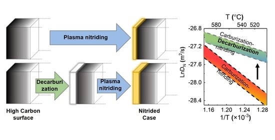
3.3. The Kinetics of Nitrogen Diffusion during Plasma Nitriding

Since surface can be easily saturated with the nitrogen species during plasma bombarding the surface, and no white nitride layer was observed in M50 or M50NiL nitrided samples, nitrogen diffusion into the matrix is the primary rate-limiting step [16,22]. Therefore, the kinetics of nitriding follows the parabolic rate law, i.e., the thickness of the nitrided layer (Δ) can be expressed by Equation (1) [23],
Δ 2 = k 1 D N t
where DN (in m2/s) is the diffusivity of N in steel, t (in s) is the nitriding time, and k1 is a concentration-dependent constant. The dependence of DN on temperature is described by the Arrhenius relationship [24,25], i.e.,
D N = D 0 e ( Q R T )
where D0 is the frequency factor (pre-exponential constant), Q (in J·mol−1) is the activation energy, R is the gas constant (8.314 J·mol−1·K−1), and T (in K) is temperature. D0 and Q can be determined by the linear fitting of ln DN and 1/T.
By analyzing the nitride layer thickness of all M50 and M50NiL samples that were nitrided at different nitriding temperatures and time as indicated in Table 1 and Table 2, a linear relation between the calculated ln DN and the reciprocal of nitriding temperatures was obtained for M50 and M50NiL samples, respectively, as shown in Figure 6. The slope of the fitted lines as labeled in Figure 6 reflects the activation energy required for nitrogen atoms to diffuse upon plasma nitriding, and it can imply carbon’s hindering effect on nitrogen atoms. It is reasonable to find that M50NiL Samples and M50 N samples that are not pre-decarburized exhibit larger activation energy compared with pre-decarburized samples due to the carbon barrier effect. Moreover, compared with the activation energy of nitrogen atom to diffuse in bcc-lattice (−74.791 kJ/mol) [26], the values obtained in this work is much smaller. This implies that the reduced activation energy is resulted fromincreased number density of grain boundary and defects via microstructure refinement during plasma nitriding.

4. Conclusions

In summary, decarburization, which is generally considered detrimental to surface properties, is innovatively applied before plasma nitriding to promote the nitriding kinetics for case-hardened M50NiL and through-hardened M50 bearing steel in this work. The influence of decarburization on properties and growth kinetics of the nitrided layer over the decarburized case is investigated.
(1)
Compared with the conventional “duplex surface engine” method, the duplex process with decarburizing step performed in this work can significantly increase the nitrided layer thickness even by more than ~100% and the surface hardness reach ~1200 HV0.1.
(2)
The analysis of nitriding kinetics shows that the pre-existing carbon atoms solutioned in Fe lattice can hinder the growth of nitride layers. Decarburization performed in air can produce a decarburized case with less carbon and residual compressive stresses, which can significantly increase the thickness of the subsequent nitride layer.
(3)
Low-nitrogen compound FeN0.076 with high hardness was produced on the modified surface of the decarburizing sample, which indicates that decarburizing can promote the occurrence of surface microstructure refinement via spinodal decomposition during plasma nitriding. Under the same nitriding conditions, the nanostructure can enhance nitrogen diffusion into the matrix along grain boundaries.

Author Contributions

Conceptualization, F.Y.; methodology, F.Y. and J.Y.; validation, F.Y. and J.Y.; formal analysis, F.Y. and J.Y.; resources, M.Y. and Y.X.; data curation, F.Y., J.Y., and B.C.; writing—original draft preparation, F.Y., J.Y., and Y.Y.; writing—review and editing, M.Y., Y.Z., and Y.Y.; visualization, F.Y.; supervision, M.Y.; project administration, M.Y.; funding acquisition, M.Y. and Y.Z. All authors have read and agreed to the published version of the manuscript.

Funding

This research was funded by National Key Research and Development Program of China (2018YFB2001901) and National Key Research and Development Program of China (2017YFB0304601).

Institutional Review Board Statement

Not applicable.

Informed Consent Statement

Not applicable.

Data Availability Statement

Data presented is original.

Acknowledgments

This work was supported by National Key Research and Development Program of China through award numbers 2018YFB2001901 and 2017YFB0304601.

Conflicts of Interest

The authors declare no conflict of interest.

References

  1. Bhadeshia, H. Steels for bearings. Prog. Mater. Sci. 2012, 57, 268–435. [Google Scholar] [CrossRef]
  2. Flodström, I. Nitrocarburizing and High Temperature Nitriding of Steels in Bearing Applications; Chalmers University of Technology: Göteborg, Sweden, 2012; pp. 34–36. [Google Scholar]
  3. Ooi, S.; Bhadeshia, H.K.D.H. Duplex Hardening of Steels for Aeroengine Bearings. ISIJ Int. 2012, 52, 1927–1934. [Google Scholar] [CrossRef] [Green Version]
  4. Rhoads, M.; Johnson, M.; Miedema, K.; Scheetz, J.; Williams, J. Advances in Steel Technologies for Rolling Bearings. Introduction of Nitrided M50 and M50NiL Bearings into Jet Engine Mainshaft Applications. In Bearing Steel Technologies; ASTM International: Washington, DC, USA, 2015; Volume 10. [Google Scholar]
  5. Streit, E.; Brock, J.; Poulin, P. Performance Evaluation of “Duplex Hardened” Bearings for Advanced Turbine Engine Applications. J. ASTM Int. 2006, 3, 1–9. [Google Scholar] [CrossRef]
  6. Bell, T.; Dong, H.; Sun, Y. Realising the potential of duplex surface engineering. Tribol. Int. 1998, 31, 127–137. [Google Scholar] [CrossRef]
  7. Davies, D. Duplex Hardening: An Advanced Surface Engineering Technique for Helicopter Transmissions. In Surface Engineering; Springer: Berlin/Heidelberg, Germany, 1990; pp. 228–237. [Google Scholar]
  8. Tsujikawa, M.; Yamauchi, N.; Ueda, N.; Sone, T.; Hirose, Y. Behavior of carbon in low temperature plasma nitriding layer of austenitic stainless steel. Surf. Coat. Technol. 2005, 193, 309–313. [Google Scholar] [CrossRef]
  9. Duarte, M.C.; Godoy, C.; Wilson, J.A.-B.; Godoy, G. Analysis of sliding wear tests of plasma processed AISI 316L steel. Surf. Coat. Technol. 2014, 260, 316–325. [Google Scholar] [CrossRef]
  10. Tsujikawa, M.; Yoshida, D.; Yamauchi, N.; Ueda, N.; Sone, T. Surface Modification of SUS304 Stainless Steel Using Carbon Push-Ahead Effect by Low Temperature Plasma Nitriding. Mater. Trans. 2005, 46, 863–868. [Google Scholar] [CrossRef] [Green Version]
  11. Tsujikawa, M.; Yoshida, D.; Yamauchi, N.; Ueda, N.; Sone, T.; Tanaka, S. Surface material design of 316 stainless steel by combination of low temperature carburizing and nitriding. Surf. Coat. Technol. 2005, 200, 507–511. [Google Scholar] [CrossRef]
  12. Bloyce, A.; Sun, Y.; Li, X. Duplex thermochemical processing of M 50 NiL for gear applications. Heat Treat. Met. Birm. 1999, 26, 37–40. [Google Scholar]
  13. Egert, P.; Maliska, A.; Silva, H.; Speller, C. Decarburization during plasma nitriding. Surf. Coat. Technol. 1999, 122, 33–38. [Google Scholar] [CrossRef]
  14. Zhao, X.; Guo, J.; Wang, H.; Wen, Z.; Liu, Q.; Zhao, G.; Wang, W. Effects of decarburization on the wear resistance and damage mechanisms of rail steels subject to contact fatigue. Wear 2016, 364, 130–143. [Google Scholar] [CrossRef]
  15. Hussain, K.; Tauqir, A.; Haq, A.U.; Khan, A.Q. Effect of retained austenite on gas nitriding of high strength steel. Mater. Sci. Technol. 1998, 14, 1218–1220. [Google Scholar] [CrossRef]
  16. Akbari, A.; Mohammadzadeh, R.; Templier, C.; Riviere, J. Effect of the initial microstructure on the plasma nitriding behavior of AISI M2 high speed steel. Surf. Coat. Technol. 2010, 204, 4114–4120. [Google Scholar] [CrossRef]
  17. Calliari, I.; Dabalà, M.; Ramous, E.; Zanesco, M.; Gianotti, E. Microstructure of a Nitrided Steel Previously Decarburized. J. Mater. Eng. Perform. 2006, 15, 693–698. [Google Scholar] [CrossRef]
  18. Yan, M.; Chen, B.; Li, B. Microstructure and mechanical properties from an attractive combination of plasma nitriding and secondary hardening of M50 steel. Appl. Surf. Sci. 2018, 455, 1–7. [Google Scholar] [CrossRef]
  19. Wang, J.; Zou, H.; Li, C.; Qiu, S.; Shen, B. The spinodal decomposition in 17-4PH stainless steel subjected to long-term aging at 350 °C. Mater. Charact. 2008, 59, 587–591. [Google Scholar] [CrossRef]
  20. Yao, J.; Yan, F.; Yan, M.; Zhang, Y.; Huang, D.; Xu, Y. The mechanism of surface nanocrystallization during plasma nitriding. Appl. Surf. Sci. 2019, 488, 462–467. [Google Scholar] [CrossRef]
  21. Sasidhar, K.N.; Meka, S.R. Thermodynamic reasoning for colossal N supersaturation in austenitic and ferritic stainless steels during low-temperature nitridation. Sci. Rep. 2019, 9, 7996. [Google Scholar] [CrossRef]
  22. Sun, Y.; Bell, T. A numerical model of plasma nitriding of low alloy steels. Mater. Sci. Eng. A 1997, 224, 33–47. [Google Scholar] [CrossRef]
  23. Zagonel, L.F.; Figueroa, C.A.; Droppa, R.; Alvarez, F. Influence of the process temperature on the steel microstructure and hardening in pulsed plasma nitriding. Surf. Coat. Technol. 2006, 201, 452–457. [Google Scholar] [CrossRef]
  24. Scheuer, C.; Cardoso, R.; Mafra, M.; Brunatto, S. AISI 420 martensitic stainless steel low-temperature plasma assisted carburizing kinetics. Surf. Coat. Technol. 2013, 214, 30–37. [Google Scholar] [CrossRef] [Green Version]
  25. Yang, Y.; Yan, M.; Zhang, S.; Guo, J.; Jiang, S.; Li, D. Diffusion behavior of carbon and its hardening effect on plasma carburized M50NiL steel: Influences of treatment temperature and duration. Surf. Coat. Technol. 2018, 333, 96–103. [Google Scholar] [CrossRef]
  26. Pinedo, C.E.; Monteiro, W.A. On the kinetics of plasma nitriding a martensitic stainless steel type AISI 420. Surf. Coat. Technol. 2004, 179, 119–123. [Google Scholar] [CrossRef]
Figure 1. Schematic diagram of duplex process for (a) M50NiL steel, (b) M50 steel.
Coatings 11 00112 g001
Figure 2. (a) Optical micrograph of cross-sectional microstructure of the carburized layer of Sample C; (b) XRD pattern of Sample C surface; (c) Optical micrograph of cross-sectional microstructure of the carburized layer of Sample CD; (d) Microhardness profiles along the modified layers of Sample C and Sample CD.
Coatings 11 00112 g002
Figure 3. (a) Optical micrograph of cross-sectional microstructure of the nitrided layer of M50NiL Sample C-N nitrided at 520 °C for 4 h; (b) Microhardness profiles along the modified layers of Sample C-N and Sample CD-N nitride at 520 °C for 4 h; (c) Optical micrograph of cross-sectional microstructure of the nitrided layer of M50NiL Sample CD-N nitrided at 520 °C for 4 h; (d) XRD patterns of Sample C-N and CD-N nitride at 520 °C for 4 h.
Coatings 11 00112 g003
Figure 4. (a) Optical micrograph of cross-sectional microstructure of M50 Sample N nitrided at 500 °C for 4 h; (b) Optical micrograph of cross-sectional microstructure of M50 Sample D-N nitrided at 500 °C for 4 h; (c) XRD patterns of the surface of M50 Sample ‘Blank’ and Sample D without nitriding; (d) XRD patterns of M50 Sample N and Sample D-N nitrided at 500 °C for 4 h.
Coatings 11 00112 g004
Figure 5. (a) TEM image and (b) the corresponding SAED of the surface of the M50 Sample D-N nitrided at 500 °C for 4 h.
Coatings 11 00112 g005
Figure 6. The activation energy for plasma nitrided samples (a) M50NiL C-N samples and CD-N samples, (b) M50 N samples and D-N samples.
Coatings 11 00112 g006
Table 1. Duplex process for M50NiL.
Sample DenotationCarburizingDecarburizingPlasma Nitriding
BoostDiffusion
C930 °C,
430 min,
Cp = 1.15%
910 °C,
280 min,
Cp = 0.85%
850 °C, 30 min, Cp = 0.85%-
CD850 °C, 30 min, air
C-N850 °C, 30 min, Cp = 0.85%520 °C, 540 °C, 580 °C
4 h, 8 h, 12 h
N2:H2 = 1:1
CD-N850 °C, 30 min, air
Table 2. Duplex process for M50.
Sample DenotationSolutioning/DecarburizingTemperingPlasma Nitriding
Blank1100 °C, 20 min, vacuum520 °C, 4 h, vacuum-
D1100 °C, 20 min, air
N1100 °C, 20 min, vacuum500 °C, 520 °C, 540 °C
4 h, 8 h, 12 h
N2:H2 = 1:3
D-N1100 °C, 20 min, air
Publisher’s Note: MDPI stays neutral with regard to jurisdictional claims in published maps and institutional affiliations.

