Article

Thermal Shock Behavior and Particle Erosion Resistance of Toughened GZ Coatings Prepared by Atmospheric Plasma Spraying

1
Key Laboratory of Pressure System and Safety, Ministry of Education, East China University and Technology, Shanghai 200237, China
2
Ningbo Institute of Dalian University of Technology, Ningbo 315016, China
*
Author to whom correspondence should be addressed.
Coatings 2021, 11(12), 1477; https://doi.org/10.3390/coatings11121477
Submission received: 11 November 2021 / Revised: 28 November 2021 / Accepted: 29 November 2021 / Published: 30 November 2021
(This article belongs to the Collection Coatings: 10th Anniversary)

Abstract

:
Gadolinium zirconate with excellent high-temperature phase stability and sintering resistance has become a very promising candidate material for a new generation of thermal barrier coatings (TBCs). However, the low fracture toughness of gadolinium zirconate greatly limits its application. In this study, gadolinium zirconate (GZ) and two kinds of toughened gadolinium zirconate (GZ/YSZ prepared by mixed powder of Gd2Zr2O7 and YSZ and GSZC prepared by (Gd0.925Sc0.075)2(Zr0.7Ce0.3)2O7 powder) double-layered TBCs were prepared by atmospheric plasma spraying (APS). The fracture toughness of the GZ/YSZ coating and GSZC coating were 9 times and 3.5 times that of GZ coating, respectively. The results of thermal shock test showed that the three TBCs exhibit different failure mechanisms. During the thermal shock test, cracking occurred at the interfaces between the YSZ layer and the BC or GZ/YSZ layer, while GSZC TBC failed due to premature cracking inside the GSZC layer. The particle erosion rate of the GZ, GZ/YSZ, and GZSC coatings were 1.81, 0.48, and 1.01 mg/g, respectively, indicating that the erosion resistance of coatings is related to their fracture toughness. Furthermore, the superior erosion resistance of the GZ/YSZ and GSZC coatings can be attributed to the conversion of crack propagation path during the erosion test.

1. Introduction

Thermal barrier coatings (TBCs) with excellent thermal insulation performance are widely applied on aero and land-based turbine engines to provide thermal protection for the underlying metallic components, resulting in higher operating temperature and engine efficiency [1,2,3]. Typical TBC systems consist of four layers: a superalloy substrate; a metallic bond layer; a thermally grown oxide (TGO) layer, which is formed due to oxidation of metallic bonding layer around the interface of bonding layer and ceramic top layer [4,5]; and a ceramic top layer. With the increasingly harsh service environment, researchers have proposed double-ceramic-layered (DCL) TBCs which exhibit better comprehensive performances than single-ceramic-layered (SCL) TBCs [6]. Atmospheric plasma spraying (APS) and electron-beam physical vapor deposition (EB-PVD) are the two most common methods to deposit thermal barrier coatings [7]. Additionally, a variety of emerging coating preparation techniques such as solution precursor plasma spray (SPPS) and plasma-spray physical vapor deposition (PS-PVD) are being investigated and developed due to their unique microstructure [8,9]. However, at present, APS is still the most widely used spraying technology due to its low production cost and versatility.
For TBC application, such as low thermal conductivity, high thermal expansion coefficient, high fracture toughness, and high erosion resistance, 6–8 wt.% Y2O3-stabilized ZrO2 (YSZ) fulfills most of the desired properties. However, at elevated temperature above 1200 °C, YSZ is pushed to the upper limit due to its undesirable phase transformation, high sintering rates, and CMAS (calcium-magnesium-aluminum-silicate) degradation, which leads to a reduction of TBC durability [10,11,12]. These drawbacks limit the high-temperature capability of YSZ-based TBCs. As advanced aeroengines develop to higher thrust-to-weight ratio, their inlet temperature will further improve. Therefore, it is of great significance to explore new candidates for ceramic-layer materials with even lower thermal conductivity, better phase stability, and superior sintering resistance. During the last few decades, much attention has been put on rare-earth-doped zirconia [13,14], perovskite structure compounds (ABO3) [15,16], magnetoplumbite lanthanum hexaaluminate (LnMgAl11O19) [17,18], and pyrochlore- or fluorite-structure compounds (A2B2O7) [19]. Among various candidate materials, pyrochlore-structured Gd2Zr2O7 with excellent thermal stability, low sintering rate, and lower thermal conductivity (1.3 W/mK−1 at 1100 °C) than YSZ (1.8 W/mK−1 at 1100 °C) becomes a very promising candidate material for a new generation of high-temperature TBCs [20,21]. However, the low fracture toughness of Gd2Zr2O7 limits its further application. As reported, the plasma-sprayed GZ coating has poor thermal shock resistance, mainly due to its low fracture toughness [22]. Therefore, the toughening of Gd2Zr2O7 is considerably necessary.
In general, the main toughening mechanisms of ceramic materials include microcracking [23], nanofication [24], fiber/whisker reinforcement [25], and grain bridging [26]. On the one hand, the addition of the second phase can improve fracture toughness by hindering crack propagation. Many researchers have chosen YSZ as the second phase to toughen Gd2Zr2O7 due to the high fracture toughness of YSZ. Zhang et al. [27] studied Gd2Zr2O7/8 wt.%YSZ composite ceramics and proved that the addition of YSZ can effectively enhance fracture toughness of samples. Ma et al. [28] found that the fracture toughness of Gd2Zr2O7/ZrO2(3Y) composite materials increased with ZrO2(3Y) content, and the stress-induced phase transformation was considered as the main toughening mechanism. Zhong et al. [29] prepared GZ-YSZ composite coating and found that the fracture toughness of GZ was improved by incorporating YSZ into GZ matrix and the thermal shock resistance of GZ-YSZ composite coating was enhanced compared to monolithic GZ coating. On the other hand, much research has been placed on the phase compositions and thermophysical properties of rare-earth-doped Gd2Zr2O7 (A2B2O7) ceramic materials. A2B2O7 composites have ordered pyrochlore or defected fluorite structure, which is mainly determined by the average radius ratio of A3+ and B4+ (r(A3+)/r(B4+)) [30]. The decrease of the r(A3+)/r(B4+) value would reduce the ordering degree of pyrochlore structure, and pyrochlore–fluorite phase transformation occurs when the r(A3+)/r(B4+) value is smaller than 1.46 [31]. Wang et al. [32] prepared (Gd1−xScx)2Zr2O7 ceramics by doping a Sc atom at the A-site of Gd2Zr2O7, and proposed that (Gd1−xScx)2Zr2O7 exhibited fluorite structure when x > 0.075 and their fracture toughness increased with the increase of Sc2O3 content. Zhang et al. [33] introduced an Ce atom to the B-site of Gd2Zr2O7 and measured the thermophysical and mechanical properties of Gd2(CexZr1−x)2O7 ceramics. Zhao et al. [34] compared the properties of Gd2Zr2O7 doped with different types of guest ions (Ti4+, Hf4+, and Ce4+) into the B-site using first principles, and proved that the partial replacement of Zr4+ in Gd2Zr2O7 improved thermal properties of Gd2Zr2O7, and the doping of Ce4+ exhibit better effects. However, few studies have reported the performance of TBCs prepared with rare-earth-doped Gd2Zr2O7 materials and the thermophysical properties of coatings may be completely different from those of ceramic bulks.
Therefore, in this study, the DCL TBCs consisting of the 8YSZ as the bottom ceramic layer and the GZ and toughened GZ as the top ceramic layer were deposited by APS. The bottom YSZ layer was designed to relieve thermal stress caused by mismatch of thermal expansion coefficient (TEC) between the BC and GZ layers, simultaneously, solving the compatibility issues of GZ single-layered TBCs with the TGO grown in situ [35]. The phase composition and mechanical properties of the coatings were measured to evaluate the effect of different toughening mechanisms on fracture toughness. In order to further compare the performance of the various TBCs, the failure modes of the coatings fabricated from different gadolinium zirconate materials under thermal shock and erosion test were analyzed and discussed.

2. Materials and Methods

2.1. Coating Deposition

In this study, all coatings were deposited by plasma spraying. Prior to spray, superalloy substrate (GH3230) with 3 mm thickness was grit blasted and then ultrasonic cleaned with alcohol. A commercially available NiCrAlY powder (45–106 μm, Beijing Sunspraying New Material Co., Ltd., Beijing, China) was used to deposit the bond coating. As for the ceramic bilayer, the bottom layers were all deposited with 8YSZ powder and the top layers were deposited using gadolinium zirconate powder, mixed powder of gadolinium zirconate and YSZ, and rare-earth-doped gadolinium zirconate powder ((Gd0.925Sc0.075)2(Zr0.7Ce0.3)2O7). For simplicity, these coatings are called as GZ, GZ/YSZ, and GSZC TBCs respectively. Figure 1 depicts the morphologies of the powders for outer layer, which exhibit a subspheroidal or erythrocyte-like shape. The mixed powder of gadolinium zirconate and YSZ contains two feedstocks in a mass ratio of 1:1. It can be seen under scanning electron microscopy (SEM, HITACHI, Tokyo, Japan) that the two powders are evenly dispersed (shown in Figure 1b). Figure 2 shows particle size distributions of the powders. Gadolinium zirconate powder and the mixed powder of gadolinium zirconate and YSZ have approximately similar particle size distributions (D50 ≈ 40 μm), and the particle size of rare-earth-doped gadolinium zirconate powder is slightly larger than the former two. The thickness of bond coats was about 180 μm, and the total thicknesses of ceramic bilayers were approximately 600 μm. The plasma spraying parameters of each coat are summarized in Table 1.

2.2. Mechanical Properties Measurement

Mechanical properties of the as-sprayed coatings were measured by the indentation method. The Vickers hardness of the as-sprayed coatings was measured by a micro-Vickers indenter (BUEHER MICROMET5104, Akashi Corporation, Osaka, Japan). The loading and holding time were set as 300 g and 15 s, respectively. In order to increase the reliability of the data, 25 points were randomly selected for each sample. According to the morphology of the indentation and the occurrence of cracks, the crack extension force (Gc) was calculated according to the following formula [36]:
G c = 6.115 × 10 4 × a 2 × P / c 3
where a is the half-diagonal length of the indentation, c is the crack length from the center of the indentation, and P is the indentation applied load.

2.3. Thermal Shock Test

To simulate the actual service environment of TBC in an engine, the thermal shock test was carried out using a gas burner rig test setup (Shaanxi Dewei Automation Co., Ltd., Xi'an, China). The burner rig test generates extremely high temperature gradients along the thickness in the TBCs and assesses their ability to maintain structural integrity under thermal stress.
During the thermal gradient cyclic test, the surface side of the TBC (ceramic side) was heated by a propane/oxygen flame, and the backside of the sample was cooled by compressed air. By adjusting the propane/oxygen ratio in combination with changing the flow rate of the air, the surface of the TBC was sustained at 1450 ± 50 °C. At the same time, the backside temperature was kept at 950 ± 50 °C. The temperatures of the specimen at surface and backside were monitored by noncontact infrared thermometers (Smart Sensor Industrument Co., Ltd, Dongguan, China) with a range of −18 to 1650 °C. One thermal cycle was defined as follows: heating process—the temperature of specimen surface was heated to the preset temperature of 1450 ± 50 °C (in about 50 s); holding process—the temperature of the specimen surface was sustained at 1450 ± 50 °C (for about 70 s); and cooling process—the temperature of specimen surface was dropped from 1450 ± 50 °C to about room temperature (in about 120 s). During the burner rig test, the buckling and delamination were identified easily by the brighter surface. The temperature of the failed surface rose rapidly because the thermal conductivity of the cracked coating was hindered. The failure criterion for the coatings was defined as an observation of 10% area delamination of the top coat. The lifetime of TBCs was defined as the number of thermal cycles when the failure criterion was reached.

2.4. Particle Erosion Test

The particle erosion test was conducted at room temperature using a homemade erosion tester. Irregular alumina particles with a mean size of approximately 50 μm were chosen as erodent particles. Before the erosion test, the as-sprayed TBC samples were weighed using an analytical balance (SHIMADZU, Kyoto, Japan). During the erosion process, the samples were exposed to successive increments of 5 g erodent at a feed rate of ~2 g/min and a velocity of 110 m/s. To create higher erosion rates, an impingement angle of 90° was chosen in this study [37]. After each increment, the specimens were cleaned in order to remove the erodent particles remaining on the sample after the test, as remaining particles could influence the weight loss measurements. The cleaned specimens were weighed using the sensitive weighing balance with a precision of up to four decimal digits. Two specimens of each TBC variation were tested. One of the tested TBC samples was used for top surface analysis and the other used for the cross-sectional analysis. Each specimen was eroded for a total of 6 data points and the erosion rate calculated as the slope of the linear portion of the graph.

2.5. Characterization

Phase analysis of the powders and coatings was conducted by X-ray diffraction (XRD, D/Max2550VB/PC, RIGAKU, Tokyo, Japan) with Cu Kα radiation at a scan rate of 10°/min within a diffraction angle of 20–80°.
A metallographic polishing procedure was employed to prepare cross-section samples of coatings. The cross-section morphologies of as-sprayed and failed TBCs were investigated by SEM.

3. Results

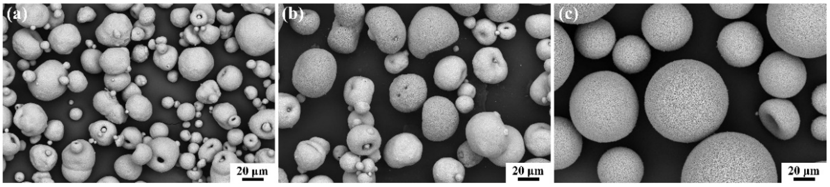
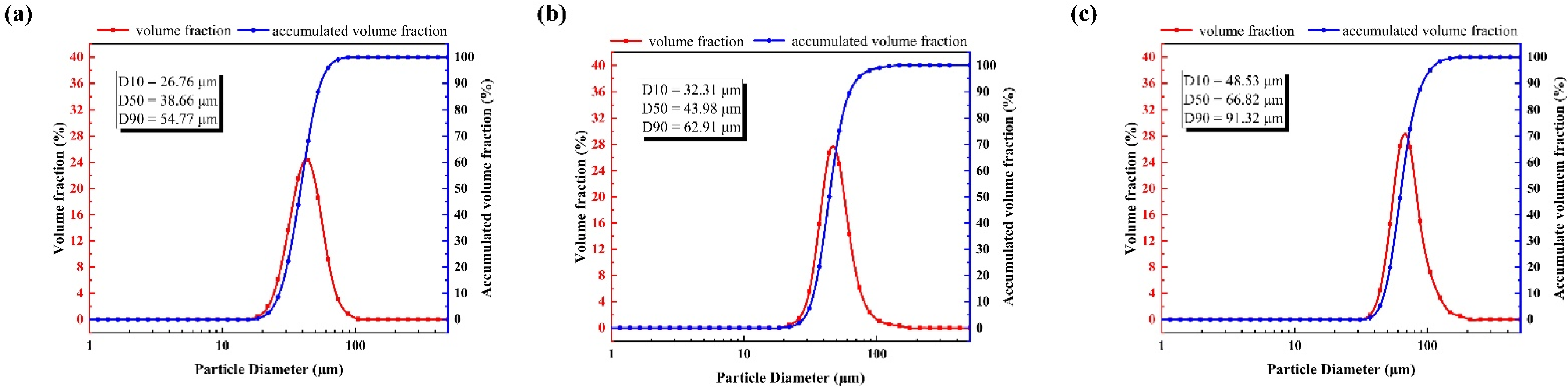
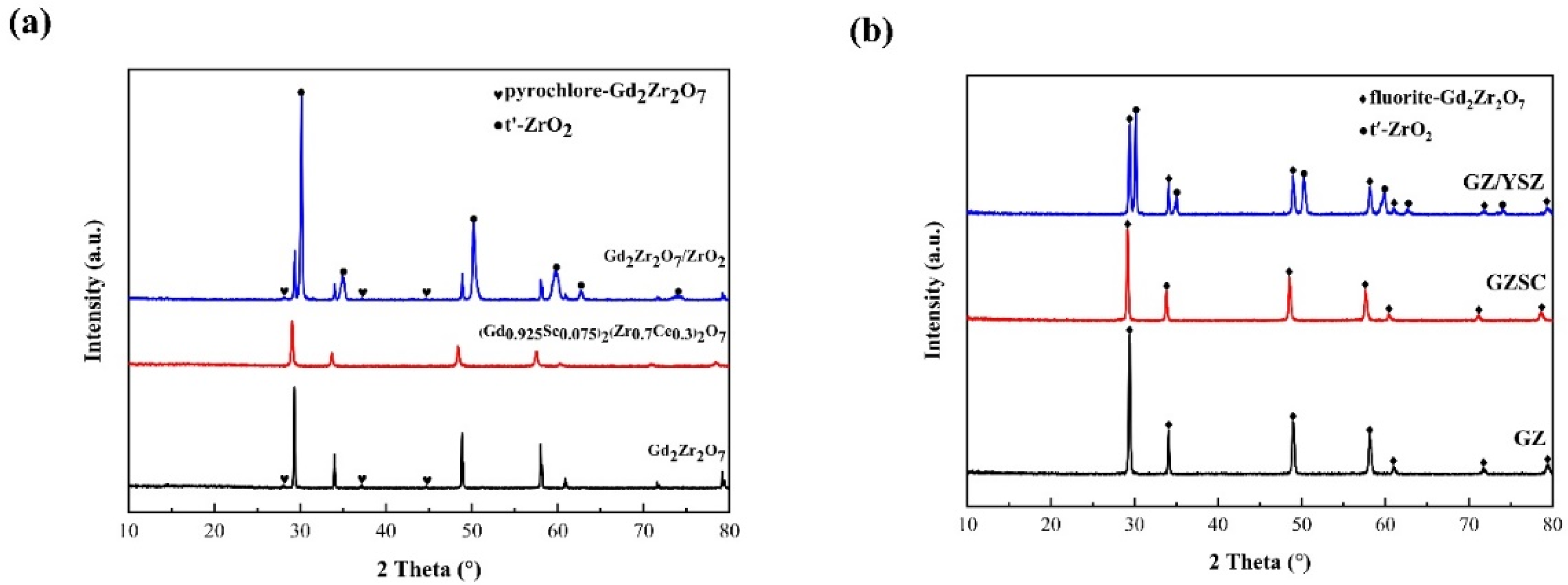
3.1. Characterization

Figure 3a shows the XRD patterns of the powders. Gd2Zr2O7 powders exhibit pyrochlore structure, which is identified by the presence of representative superlattice peaks at 2θ ≈ 28° (311), 37° (331), and 45° (511) [38,39]. However, no superlattice peak could be found in the XRD patterns of (Gd0.925Sc0.075)2(Zr0.7Ce0.3)2O7 powders, indicating that rare-earth-doped gadolinium zirconate powder exhibits fluorite structure. The doping elements Sc and Ce reduced the atomic radius ratio of the A-site element and the B-site element of the A2B2O7-type zirconate. The ratio is less than the critical value of the phase transition of the pyrochlore structure and the defective fluorite structure, thereby obtaining (Gd0.925Sc0.075)2(Zr0.7Ce0.3)2O7 powder with the defective fluorite structure. Meanwhile, it can be seen that the XRD patterns of (Gd0.925Sc0.075)2(Zr0.7Ce0.3)2O7 shift to lower angles compared to Gd2Zr2O7, suggesting an expansion of the unit cell [32]. The diffractogram patterns of the mixed powder of gadolinium zirconate and YSZ exhibit that it is composed of nonequilibrium tetragonal ZrO2 and the Gd2Zr2O7 with pyrochlore structure.
Figure 3b shows the XRD patterns of the as-sprayed coatings. The GZ coating shows a defect fluorite phase (cubic phase), although gadolinium zirconate powders exhibit pyrochlore phase. In the process of plasma spraying, there is insufficient time for the oxygen ion vacancies and cations to be arranged in an orderly fashion during the solidification, which results in the defect fluorite structure GZ coating [40]. The GZ coating with defect fluorite structure is more desirable as it possesses better fracture toughness than the GZ coating with pyrochlore structure. The GSZC coating still shows a defect fluorite phase, and the XRD patterns of GSZC coating shift to lower angles. The GZ/YSZ coating shows a combination of nonequilibrium tetragonal zirconia phase and cubic defect fluorite gadolinium zirconate phase. Furthermore, the GZ/YSZ coating prepared by APS did not form an entirely new third phase. The retention of two independent phases in a composite coating can provide beneficial properties of the two phases, such as high fracture toughness of YSZ and high-temperature capability of GZ.
Figure 4 presents the microstructure of the as-sprayed GZ, GZ/YSZ, and GSZC coatings. All coatings exhibited the typical microstructure deposited by APS. Unmelted particles, pores, and interlaminar cracks were distributed in the coatings. It is these characteristic microstructures that give coatings an excellent thermal property. The porosity of GZ, GZ/YSZ, and GSZC, estimated by image analysis of backscattered electron (BSE) images of the cross-section (×1000 magnification, three typical images for each coating) is approximately 8.81%, 9.79%, and 10.41%, respectively. By comparison, some differences can be found in three kinds of coatings. Due to the composite material in the GZ/YSZ coatings, two different phases can be identified in the BSE images in which the bright phase is GZ and the dark one is YSZ. Additionally, a few vertical cracks can be noted in the GZ and GZ/YSZ coatings, but not in the GSZC coatings. It seems that coatings deposited by coarse powder have more difficulty forming vertical cracks during the spraying process.
Figure 5 shows the mechanical properties of the as-sprayed coatings. The results of the hardness test indicate that the various coatings have a comparable hardness. GZ/YSZ coating possesses the highest hardness (711 HV) and GSZC coating possesses the lowest hardness (548 HV). According to the morphology of the indentation and the occurrence of cracks, the fracture toughness was characterized by the crack extension force (Gc). The results show that the GZ/YSZ coating and GSZC coating possess approximately 9-fold and 3.5-fold greater fracture toughness, respectively, when compared with the GZ coating.

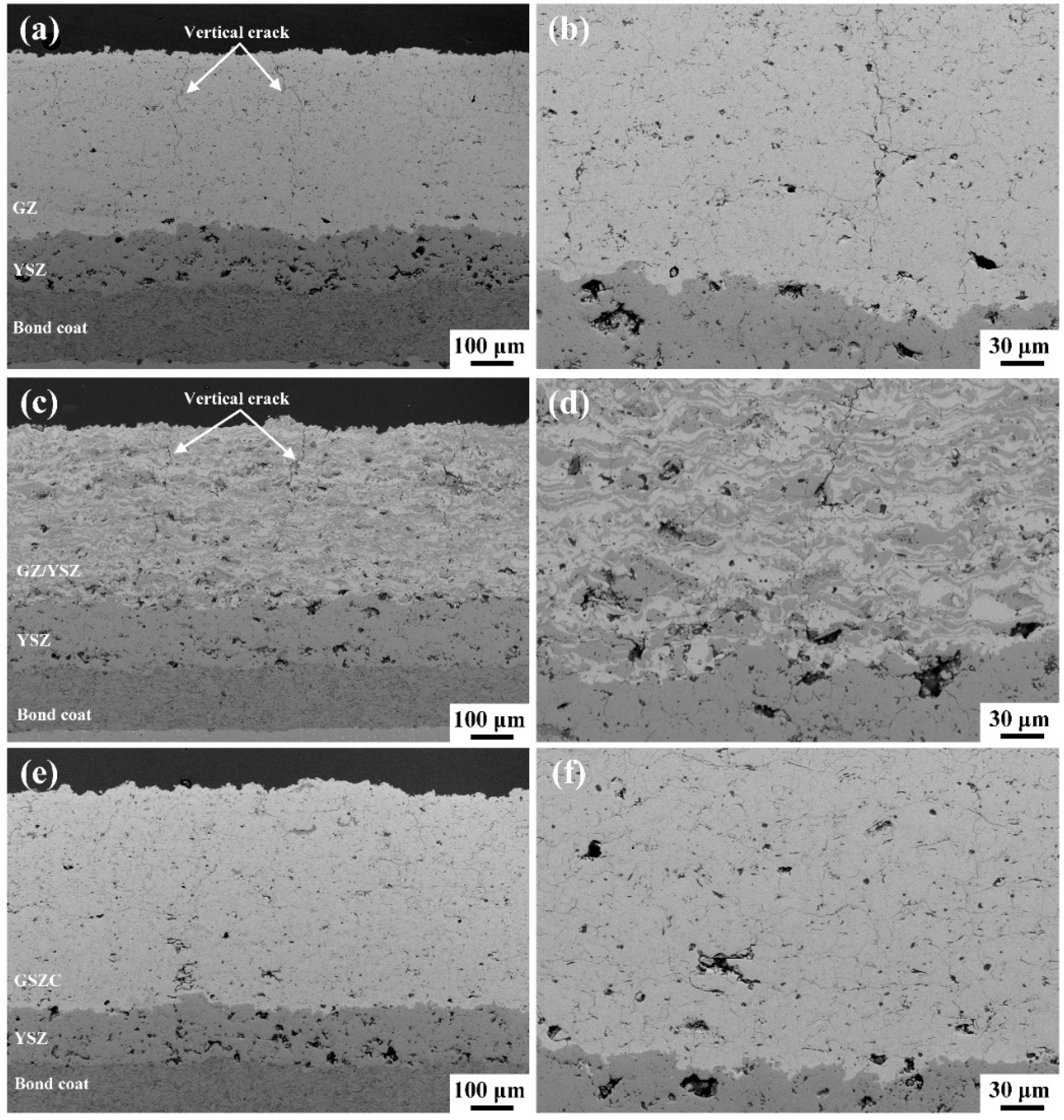
3.2. Thermal Shock Resistance

The thermal shock lifetimes of the GZ, GZ/YSZ, and GSZC coatings were 38, 33, and 7, respectively. The GZ coating and GZ/YSZ coating have approximate thermal shock lifetimes. The thermal shock lifetime of the GSZC coating is evidently lower than the former two. By observing the cross-sectional SEM images of the failed samples, three kinds of TBCs exhibit different failure behaviors.
From the macroscopic morphologies of the GZ coating during thermal shock (Figure 6b) and after thermal shock (Figure 6a), it can be seen that initial spallation originated from the edge of the specimen due to an edge effect and gradually extended to the center. The ceramic top coat was peeled off and the bond coat was exposed to air. From the SEM images of spalling area 1 (Figure 6c,d), obvious cracking occurred above the interface of bond coat and YSZ bottom ceramic layer. From Figure 6g,h, it can be seen that some microcracks were propagating, which mostly originated from the internal defects in the YSZ bottom layer. However, the formation and thickening of the TGO layer is not obvious, which indicates that the TGO layer is not a contributing factor to the cracking of the GZ coating in this test [41]. The thermal stress caused by the material thermal expansion mismatch is the main reason for the cracking of the coating. During the thermal shock test, the vertical cracks inside the GZ layer can partly increase the strain tolerance of the coating, thereby decreasing the thermal stress in the GZ layer. Additionally, the YSZ bottom layer with excellent fracture toughness improved the crack resistance of the entire ceramic layer. These characteristic structures improved the thermal shock lifetime of the GZ coating. The cracking that occurred at the interface of the bond coat and YSZ layer did not directly cause the spallation of the ceramic layer. The crack needed to pass through the YSZ layer with higher fracture toughness, and then spallation occurred. It can be confirmed from Figure 6c–f that the cracks from the interface of the bond coat and YSZ layer passed through the YSZ layer, and the imminent coalescence of interface cracks and vertical cracks inside the GZ layer led to the spallation.
Figure 7a,b shows the macroscopic morphologies of the GZ/YSZ coating during thermal shock and after thermal shock. The GZ/YSZ coating did not peel off until the 33rd thermal shock, and it peeled off in a large area during the 33rd thermal shock. This failure behavior is associated with the crack evolution during the thermal shock test. In the early stage of the thermal shock test, some initial pores and other defects in the coating gradually developed into cracks under the action of thermal stress, as shown in Figure 7g,h. As the number of thermal shock cycles increased, these cracks propagated and merged. When a large number of cracks merged in the coating, the coating peeled rapidly and failed [42]. Compared to the GZ top ceramic layer, the thermal expansion coefficient (TEC) of the GZ/YSZ layer is closer to that of the YSZ layer. However, cracking occurred at the interface of the YSZ layer and GZ/YSZ layer, while few cracks expanded at the interface of the bond coat and YSZ layer (Figure 7c–f). There may be two factors that caused this failure behavior. During the plasma spraying process, gadolinium zirconate splats and YSZ splats stacked on each other and finally formed the GZ/YSZ coating. The GZ/YSZ layer prepared by two types of feedstock simultaneously may have a weak combination with the bottom YSZ layer due to structural discontinuity. On the other hand, sintering may be another factor that caused this failure behavior. Compared to gadolinium zirconate, YSZ has poor sintering resistance, and the GZ/YSZ coating is prone to sinter compared to GZ coating [43]. During the thermal shock test, sintering enlarged the stiffness of the overall GZ/YSZ coating, which makes cracking tend to occur at the interface of the GZ/YSZ and YSZ layers.
Figure 8 shows macroscopic and cross-sectional morphologies of the GSZC coating after the thermal shock test. It can be noticed that the GSZC coating shows a drastically different failure mode in comparison with the first two. Cracking that occurred inside the GSZC coating directly led to spallation (Figure 8c,d). In addition to macroscopic spallation at the edge, obvious cracking occurred inside the GSZC coating, while few cracks grew at the interfaces, as represented in Figure 8e,f. Although some cracks grew at the interface of the bottom YSZ layer and GSZC layer (Figure 8g,h), the spallation of the GSZC coating caused failure before these cracks propagated. From the morphology of the as-sprayed GSZC coating, it can be seen that the GSZC coating did not form vertical cracks during spraying, which limited the strain tolerance of the GSZC coating. During the thermal shock test, horizontal cracks propagated inside the GSZC layer under the action of thermal stress due to the limited adhesion between lamellas. The poor thermal shock resistance of the GSZC coating can be attributed to the premature cracking inside the GSZC layer.

3.3. Particle Erosion Resistance

Among the as-sprayed TBCs, GZ/YSZ TBC showed the lowest erosion rate (0.48 mg/g) whereas GZ TBC showed the highest erosion rate (1.81 mg/g) when subject to the erosion test, according to Figure 9. In this study, the coating with higher fracture toughness seems to have better erosion resistance. As for coatings prepared by APS, the erosion damage mechanism is related to splats removal through crack propagation along splat boundaries [44]. During the erosion test, the boundaries of overlapped splats damaged gradually due to the limited bonding at the interfaces between lamellas. Therefore, the erosion resistance of ceramic coatings is controlled by fracture toughness [45]. To understand the erosion mechanism of the three kinds of TBCs, SEM analysis of the coatings after erosion was carried out.
Figure 10 depicts the typical erosion morphologies of the GZ coating after the erosion test. It can be seen that the outer GZ layer almost completely peeled off at the center of the erosion pit, according to Figure 10c. From the image of the eroded surface (Figure 10b), an obvious fracture and spalling feature occurred. Furthermore, there are more fractured splats than spallation of splats, which can also be seen obviously in the cross-sectional image (Figure 10d). This erosion mechanism indicates that the propagation of initial vertical cracks inside the GZ splats and interlamellar cracks led to chipping and coating loss. Figure 11 shows the erosion morphologies of the GZ/YSZ coating after the erosion test. The erosion resistance of GZ/YSZ coating improves significantly by adding a second-phase YSZ with high fracture toughness. From the backscattered electron (BSE) image of the eroded surface of the GZ/YSZ coating (Figure 11b), it can be seen obviously that the darker YSZ was retained and the brighter GZ peeled off, which indicated that the spallation of the YSZ splats needed more energy compared to the GZ splats. When particles impacted on the YSZ splats, cracks propagated along the interfaces between lamellas of YSZ and GZ (Figure 11d). Furthermore, these cracks could pass through GZ splats more easily than YSZ splats, thereby forming tortuous crack propagation paths. This type of crack propagation makes it more difficult to form spallation of splats. Figure 12 displays the erosion morphologies of the GSZC coating after the erosion test. The erosion damage mechanism of the GSZC coating is similar to that of the GZ coating. However, there is more spallation of splats in the GSZC coating than in the GZ coating (Figure 12b). It seems that cracks propagated along the well-bonded lamellar interface during particle erosion, resulting in superior erosion resistance.

4. Conclusions

In this study, gadolinium zirconate (GZ) and toughened gadolinium zirconate (GZ/YSZ and GSZC) double-layered TBCs were prepared using APS. The phase compositions of powders and as-sprayed coatings were investigated. The effect of two toughening mechanisms was evaluated by the indentation method. Furthermore, the thermal shock behavior and particle erosion resistance of the toughened GZ TBC were investigated. The major useful conclusions can be summarized as follows:
  • Gd2Zr2O7 powders exhibit pyrochlore structure while (Gd0.925Sc0.075)2(Zr0.7Ce0.3)2O7 powders exhibit fluorite structure. This was due to the doping elements Sc and Ce reducing the atomic radius ratio of the A-site and B-site element of the A2B2O7-type zirconate. In addition, the mixed powder of gadolinium zirconate and zirconium oxide is composed of nonequilibrium tetragonal ZrO2 and the Gd2Zr2O7 with pyrochlore structure. After the plasma spray process, gadolinium zirconate exhibits fluorite structure due to gadolinium zirconate not having sufficient time for an orderly arrangement of the cations and oxygen ion vacancies during the solidification.
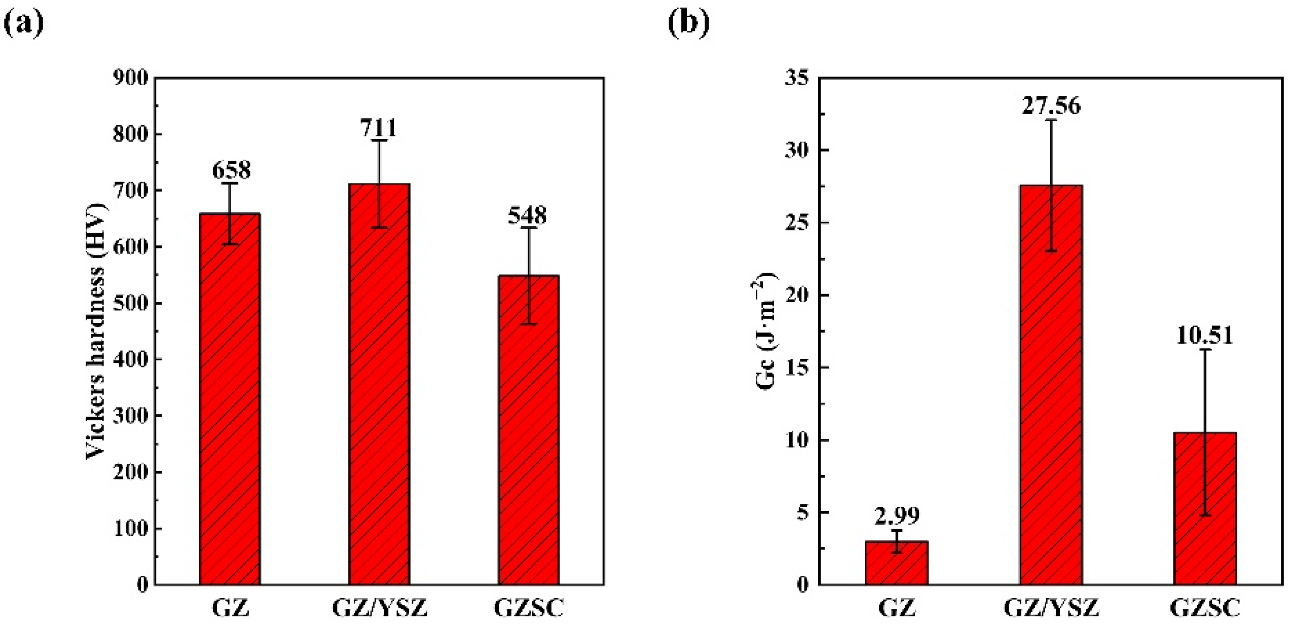
  • The fracture toughness of TBCs was characterized by the crack extension force (Gc). The results indicated that the coatings doped with zirconium oxide and rare earth elements both exhibited considerable toughening effect. GZ/YSZ coating and GSZC coating possess approximately 9-fold and 3.5-fold fracture toughness when compared with the GZ coating, respectively.
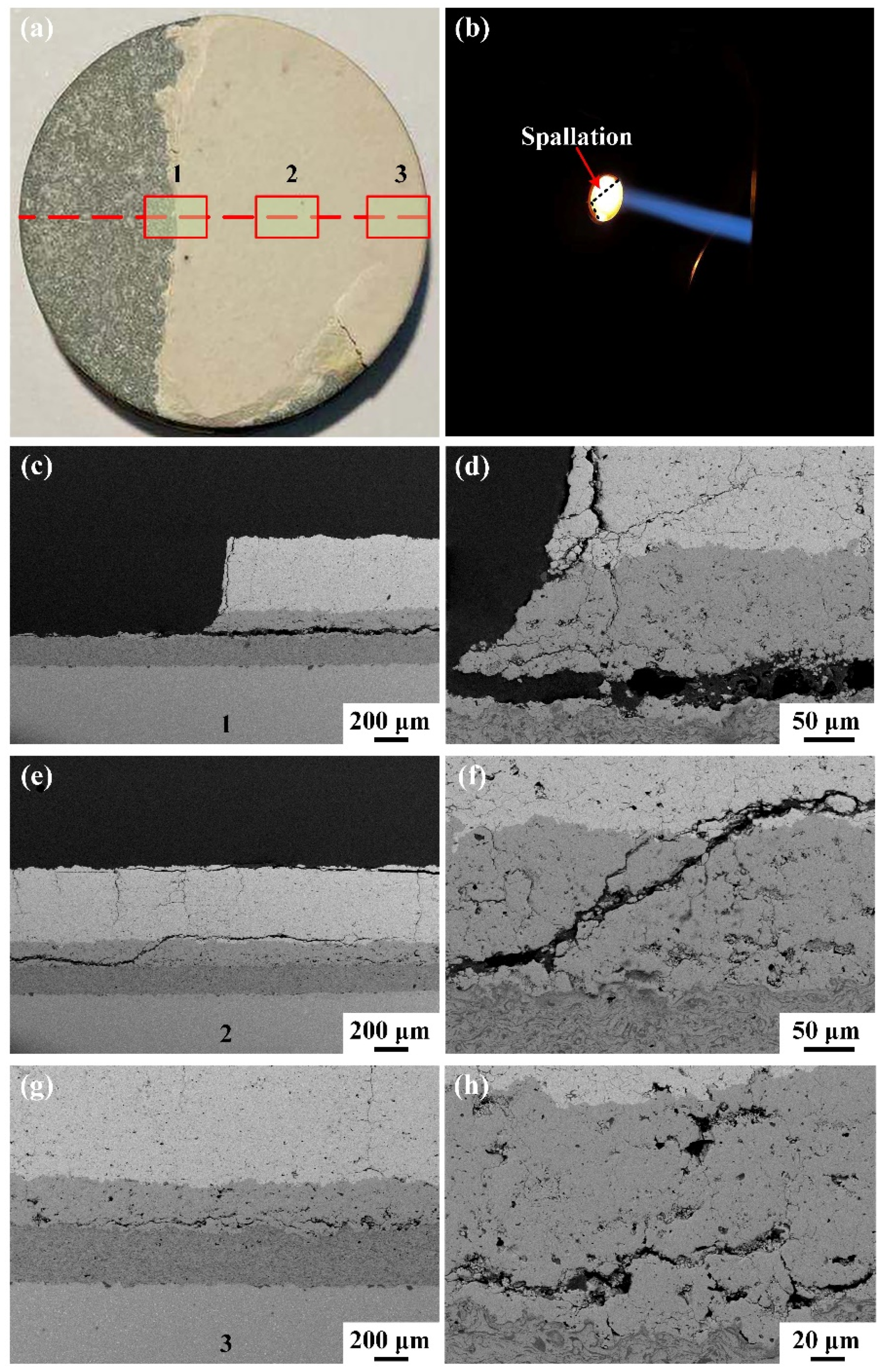
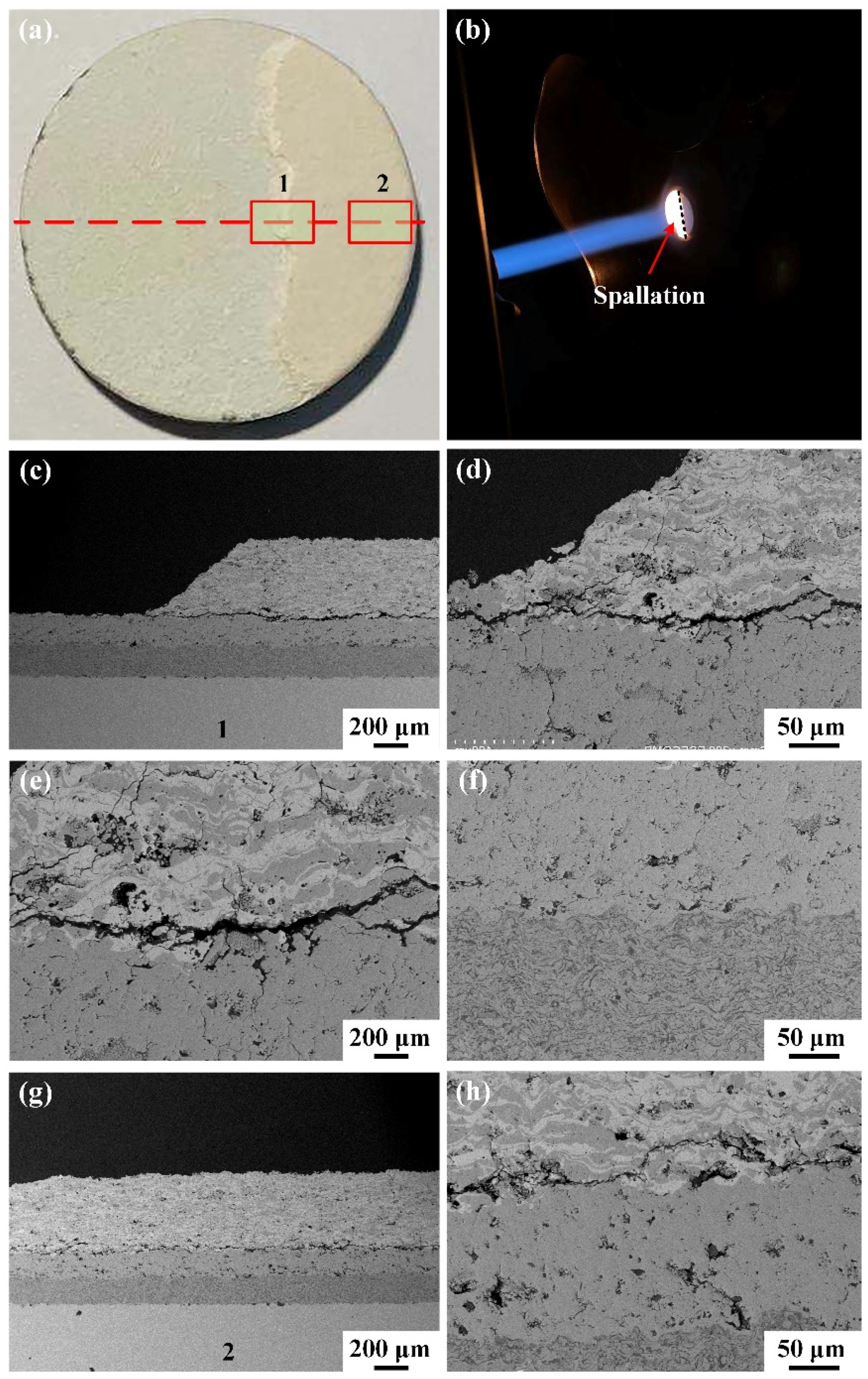
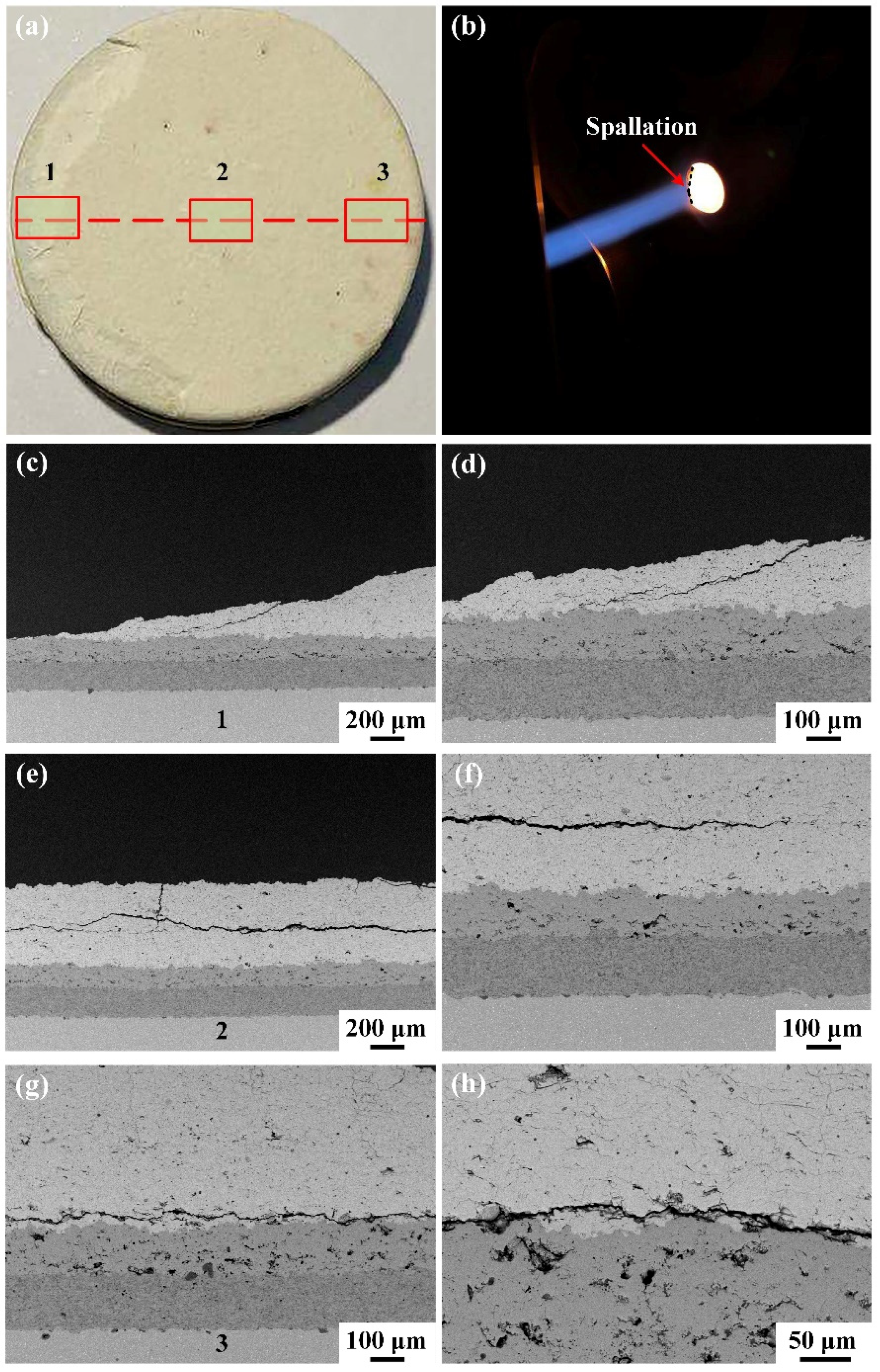
  • Three kinds of TBCs exhibit different thermal shock failure behaviors. As for the GZ coating, cracking occurred at the interface of the bond coat and YSZ bottom ceramic layer due to mismatch of the material thermal expansion. However, cracking occurred at the interface of the YSZ bottom ceramic layer and GZ/YSZ top ceramic layer in GZ/YSZ TBC during the thermal shock test, which may be caused by a weak combination of the two ceramic layers. In addition, GSZC TBC exhibits the worst thermal shock resistance due to premature cracking occurring inside the GSZC coating during the thermal shock test.
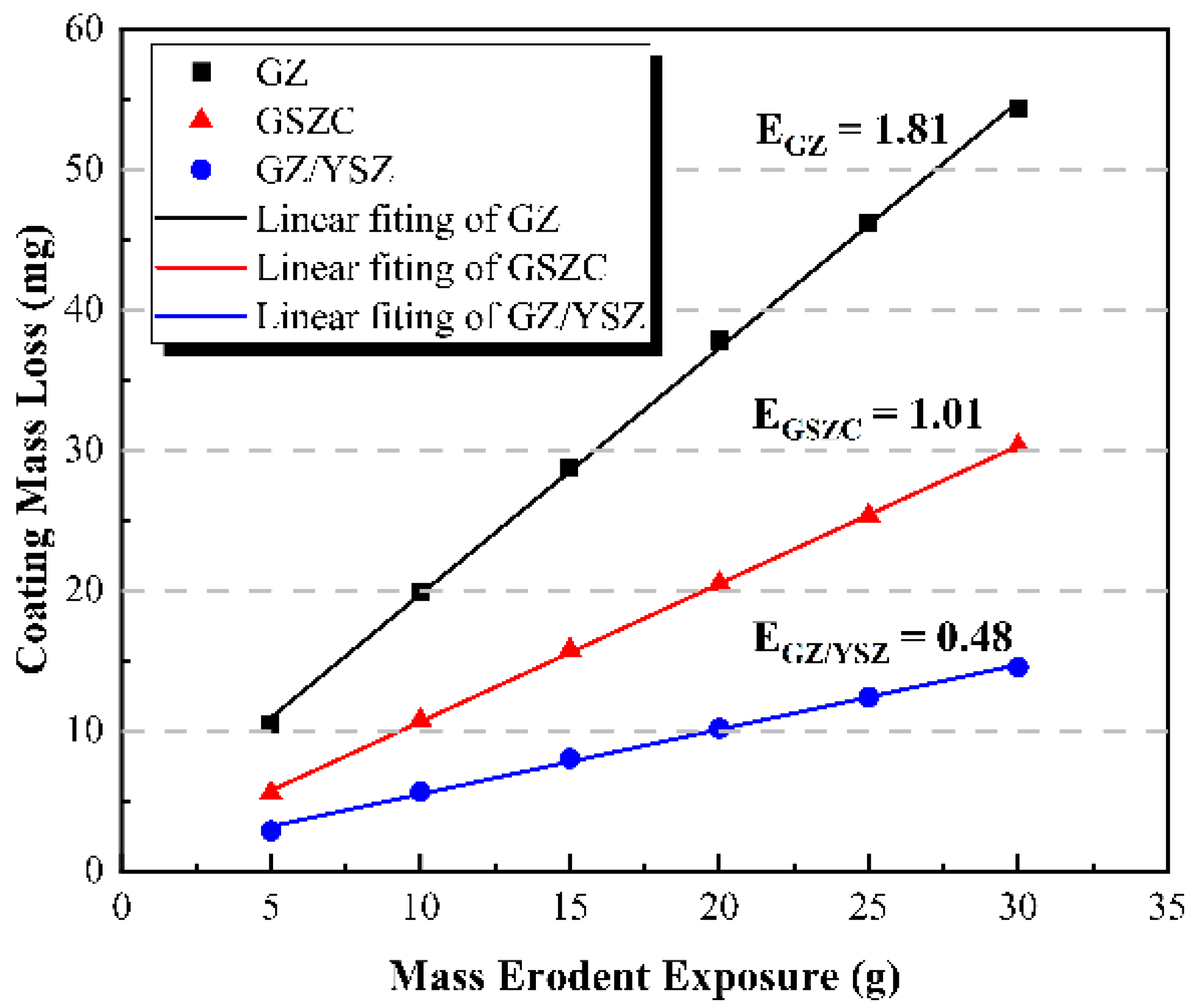
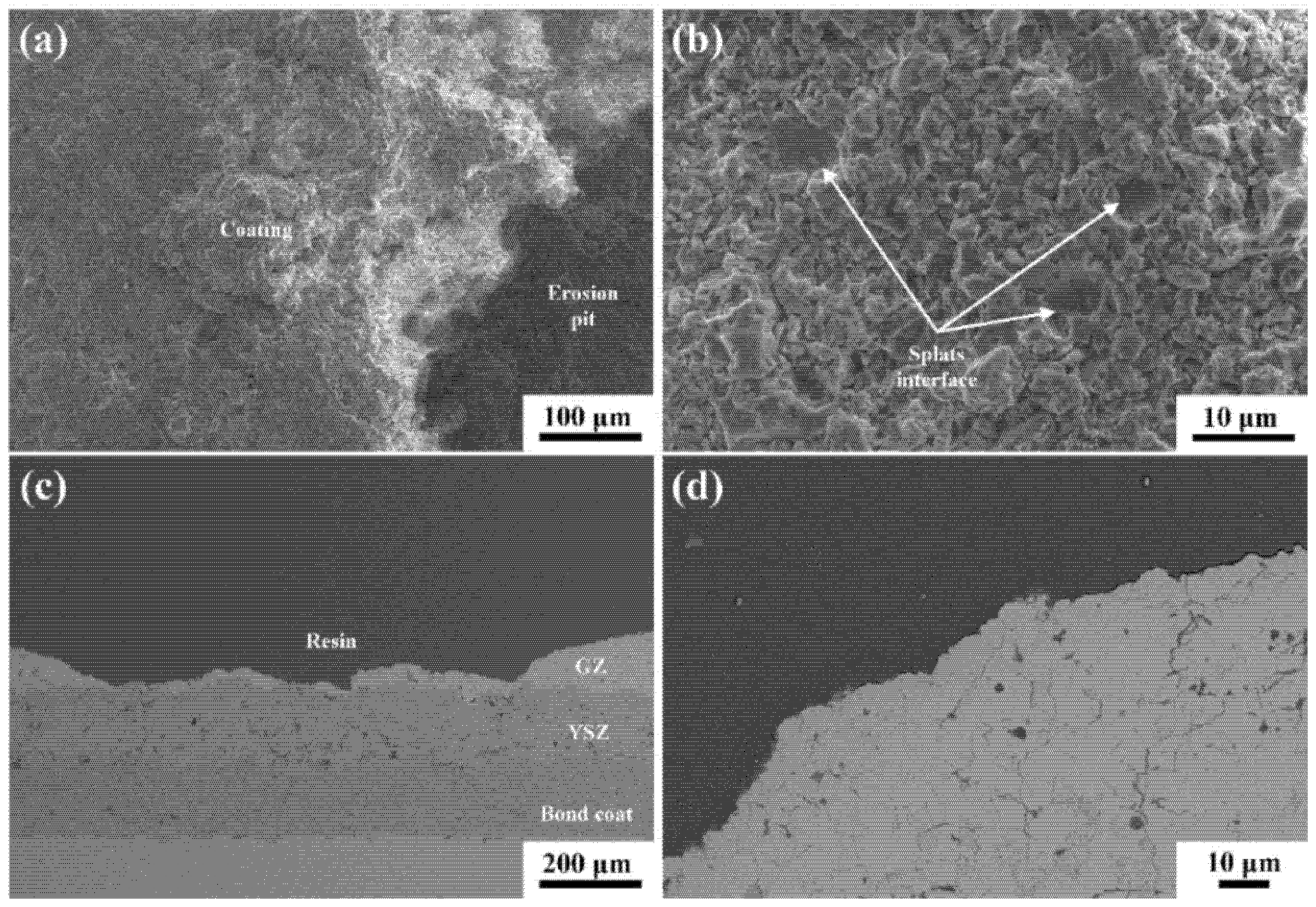
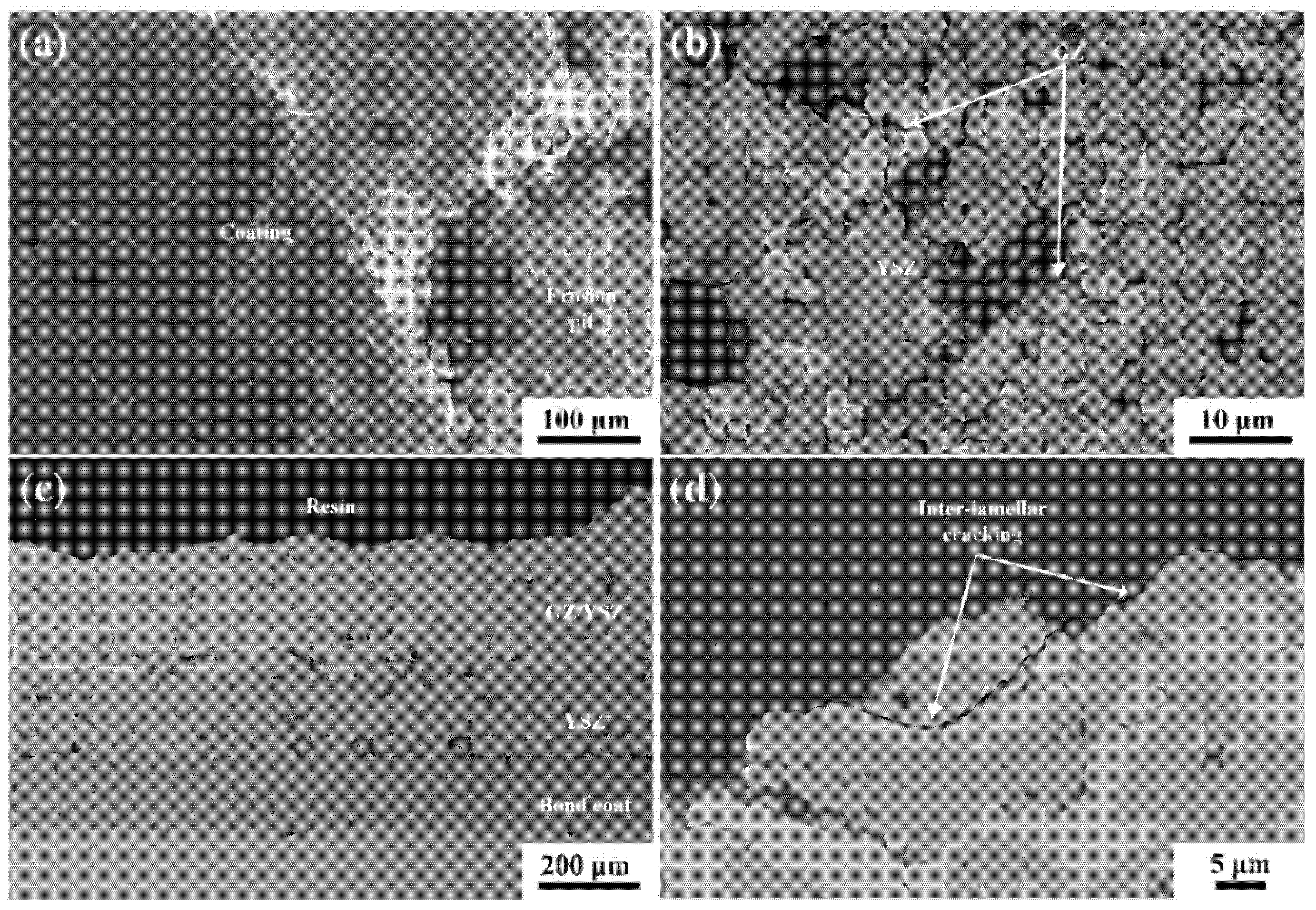
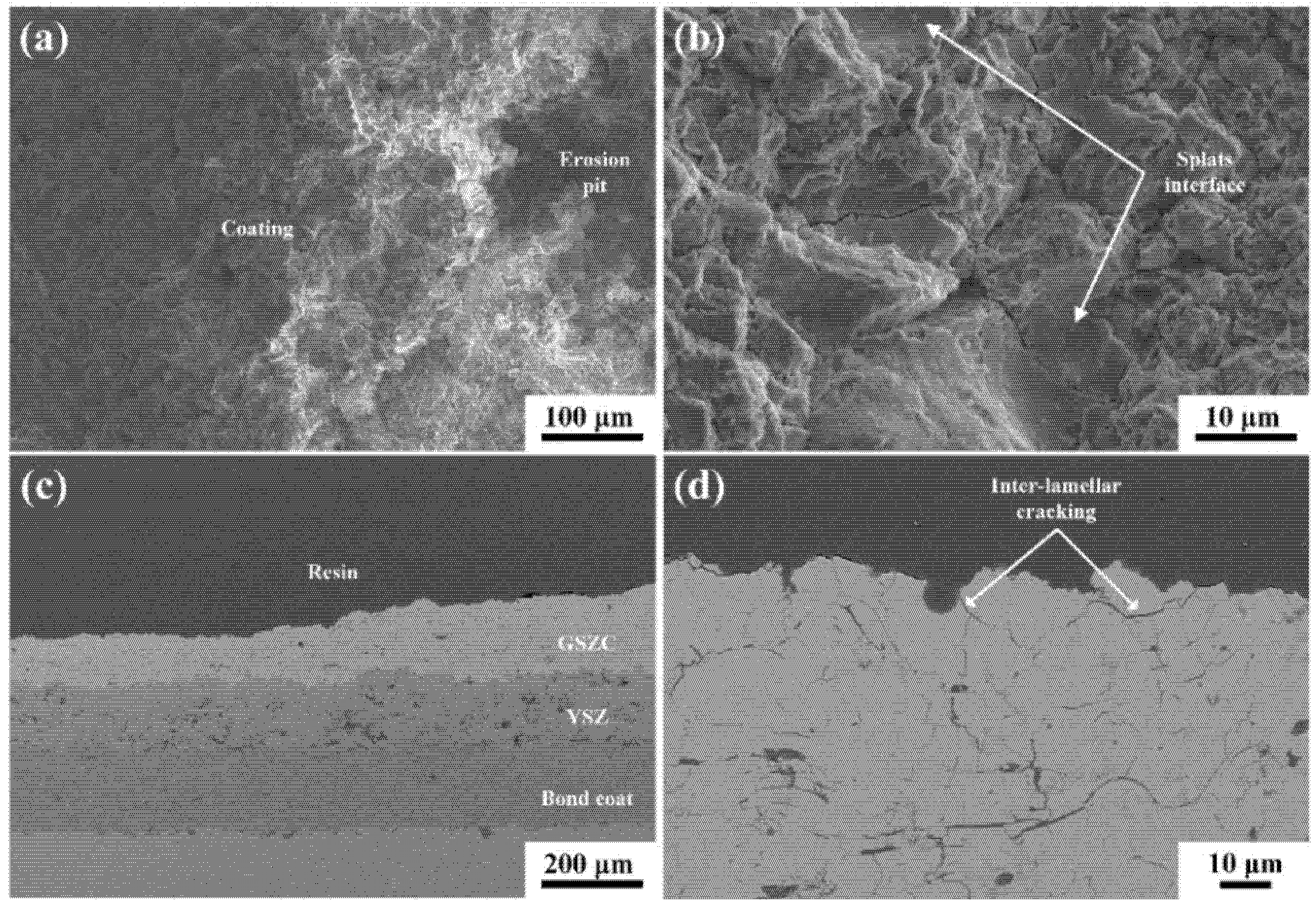
  • The particle erosion resistance of the coatings is related to their fracture toughness. The GZ/YSZ coating with highest fracture toughness exhibited the best erosion resistance. Furthermore, the superior erosion resistance of the GZ/YSZ coating can be attributed to a tortuous crack propagation path during particle erosion. Additionally, cracks propagated along the well-bonded lamellar interface of GSZC splats during the erosion test, which led to an improved erosion resistance of the GSZC coating.

Author Contributions

Conceived and designed the experiments, Z.Y. and W.W.; performed the experiments, Z.Y., S.D., H.F., T.Y. and L.W.; analyzed the data and wrote the paper, Z.Y. and W.W. All authors have read and agreed to the published version of the manuscript.

Funding

This research is sponsored by the National Natural Science Foundation of China (Grant Nos. 51775189, 52175136), Shanghai Aerospace Science and Technology Innovation Fund (Grant No. SAST2019056), Shanghai Joint Innovation Program in the Field of Commercial Aviation Engines.

Institutional Review Board Statement

Not applicable.

Informed Consent Statement

Not applicable.

Data Availability Statement

Data sharing is not applicable to this article.

Conflicts of Interest

The authors declare no conflict of interest.

References

  1. Padture, N.P. Advanced structural ceramics in aerospace propulsion. Nat. Mater. 2016, 15, 804–809. [Google Scholar] [CrossRef] [PubMed]
  2. Padture, N.P.; Gell, M.; Jordan, E.H. Thermal barrier coatings for gas-turbine engine applications. Science 2002, 296, 280. [Google Scholar] [CrossRef]
  3. Clarke, D.R.; Oechsner, M.; Padture, N.P. Thermal-barrier coatings for more efficient gas-turbine engines. MRS Bull. 2012, 37, 891–902. [Google Scholar] [CrossRef] [Green Version]
  4. Hardwicke, C.U.; Lau, Y.C. Advances in Thermal spray coatings for gas turbines and energy generation: A review. J. Therm. Spray Technol. 2013, 22, 564–576. [Google Scholar] [CrossRef]
  5. Wright, P.K.; Evans, A.G. Mechanisms governing the performance of thermal barrier coatings. Curr. Opin. Solid State Mater. Sci. 1999, 4, 255–265. [Google Scholar] [CrossRef]
  6. Lashmi, P.G.; Ananthapadmanabhan, P.V.; Unnikrishnan, G.; Aruna, S.T. Present status and future prospects of plasma sprayed multilayered thermal barrier coating systems. J. Eur. Ceram. Soc. 2020, 40, 2731–2745. [Google Scholar] [CrossRef]
  7. Feuerstein, A.; Knapp, J.; Taylor, T.; Ashary, A.; Bolcavage, A.; Hitchman, N. Technical and economical aspects of current thermal barrier coating systems for gas turbine engines by thermal spray and EBPVD: A Review. J. Therm. Spray Technol. 2008, 17, 199–213. [Google Scholar] [CrossRef]
  8. Gao, L.H.; Guo, H.B.; Wei, L.L.; Li, C.Y.; Gong, S.K.; Xu, H.B. Microstructure and mechanical properties of yttria stabilized zirconia coatings prepared by plasma spray physical vapor deposition. Ceram. Int. 2015, 41, 8305–8311. [Google Scholar] [CrossRef]
  9. Yang, T.; Ma, W.; Meng, X.; Huang, W.; Bai, Y.; Dong, H. Deposition characteristics of CeO2-Gd2O3 co-stabilized zirconia (CGZ) coating prepared by solution precursor plasma spray. Surf. Coat. Technol. 2020, 381, 125114. [Google Scholar] [CrossRef]
  10. Ballard, J.D.; Davenport, J.; Lewis, C.; Nelson, W.; Doremus, R.H.; Schadler, L.S. Phase stability of thermal barrier coatings made from 8 wt.% yttria stabilized zirconia: A technical note. J. Therm. Spray Technol. 2003, 12, 34–37. [Google Scholar] [CrossRef]
  11. Fang, H.J.; Wang, W.Z.; Huang, J.B.; Ye, D.D. Investigation of CMAS resistance of sacrificial plasma-sprayed mullite-YSZ protective layer on 8YSZ thermal barrier coating. Corros. Sci. 2020, 173, 108764. [Google Scholar] [CrossRef]
  12. Huang, J.B.; Wang, W.Z.; Li, Y.J.; Fang, H.J.; Ye, D.D.; Zhang, X.C.; Tu, S.T. Improve durability of plasma-splayed thermal barrier coatings by decreasing sintering-induced stiffening in ceramic coatings. J. Eur. Ceram. Soc. 2020, 40, 1433–1442. [Google Scholar] [CrossRef]
  13. Fang, H.J.; Wang, W.Z.; Huang, J.B.; Li, Y.J.; Ye, D.D. Corrosion behavior and thermos-physical properties of a promising Yb2O3 and Y2O3 co-stabilized ZrO2 ceramic for thermal barrier coatings subject to calcium-magnesium-aluminum-silicate (CMAS) deposition: Experiments and first-principles calculation. Corros. Sci. 2021, 182, 109230. [Google Scholar] [CrossRef]
  14. Yang, T.; Ma, W.; Meng, X.F.; Li, E.B.; Bai, Y.; Liu, C.W.; Dong, H.Y. Preparation and thermophysical properties of CeO2-Gd2O3 costabilized zirconia thermal barrier coating. J. Therm. Spray Technol. 2020, 29, 115–124. [Google Scholar] [CrossRef]
  15. Guo, H.B.; Zhang, H.J.; Ma, G.H.; Gong, S.K. Thermo-physical and thermal cycling properties of plasma-sprayed BaLa2Ti3O10 coating as potential thermal barrier materials. Surf. Coat. Technol. 2009, 204, 691–696. [Google Scholar] [CrossRef]
  16. Ma, W.; Mack, D.; Malzbender, J.; Vaßen, R.; Stöver, D. Yb2O3 and Gd2O3 doped strontium zirconate for thermal barrier coatings. J. Eur. Ceram. Soc. 2008, 28, 3071–3081. [Google Scholar] [CrossRef]
  17. Xie, X.Y.; Guo, H.B.; Gong, S.K.; Xu, H.B. Lanthanum-titanium-aluminum oxide: A novel thermal barrier coating material for applications at 1300 degrees C. J. Eur. Ceram. Soc. 2011, 31, 1677–1683. [Google Scholar] [CrossRef]
  18. Zhu, R.X.; Liu, Z.G.; Ouyang, J.H.; Zhou, Y. Preparation and characterization of LnMgAl(11)O(19) (Ln=La, Nd, Gd) ceramic powders. Ceram. Int. 2013, 39, 8841–8846. [Google Scholar] [CrossRef]
  19. Cao, X.Q.; Vassen, R.; Stoever, D. Ceramic materials for thermal barrier coatings. J. Eur. Ceram. Soc. 2004, 24, 1–10. [Google Scholar] [CrossRef]
  20. Carpio, P.; Salvador, M.D.; Borrell, A.; Sánchez, E. Thermal behaviour of multilayer and functionally-graded YSZ/Gd2Zr2O7 coatings. Ceram. Int. 2017, 43, 4048–4054. [Google Scholar] [CrossRef] [Green Version]
  21. Gok, M.G.; Goller, G. State of the Art of Gadolinium Zirconate Based Thermal Barrier Coatings: Design, Processing and Characterization, 1st ed.; IntechOpen: London, UK, 2019. [Google Scholar]
  22. Vassen, R.; Traeger, E.; Stover, D. New thermal barrier coatings based on pyrochlore/YSZ double-layer systems. Int. J. Appl. Ceram. Technol. 2004, 1, 351–361. [Google Scholar] [CrossRef]
  23. Han, L.X.; Warren, R.; Suresh, S. An experimental study of toughening and degradation due to microcracking in a ceramic composite. Acta Metall. Mater. 1992, 40, 259–274. [Google Scholar] [CrossRef]
  24. Zhou, F.; Deng, C.; Wang, Y.; Liu, M.; Wang, L.; Wang, Y.; Zhang, X. Characterization of multi-scale synergistic toughened nanostructured YSZ thermal barrier coatings: From feedstocks to coatings. J. Eur. Ceram. Soc. 2020, 40, 1443–1452. [Google Scholar] [CrossRef]
  25. Wang, C.L.; Tian, H.L.; Guo, M.Q.; Gao, J.G.; Cui, Y.J.; Liang, Y.; Tong, H.; Fang, Y.C.; Wen, X.; Wang, H. Microstructure and thermal shock resistance of AlBOw- and BNw-whisker-modified thermal barrier coatings. Ceram. Int. 2020, 46, 16372–16379. [Google Scholar]
  26. Kagawa, Y. Quantitative analysis of closure stress-crack separation curve in grain bridge toughening of polycrystalline ceramics. Mater. Sci. Eng. 1994, 176, 379–383. [Google Scholar] [CrossRef]
  27. Zhang, Y.; Malzbender, J.; Mack, D.E.; Jarligo, M.O.; Cao, X.; Li, Q.; Vaßen, R.; Stöver, D. Mechanical properties of zirconia composite ceramics. Ceram. Int. 2013, 39, 7595–7603. [Google Scholar] [CrossRef]
  28. Ma, L.; Ma, W.; Sun, X.; Ji, L.; Liu, J.; Hang, K. Microstructures and mechanical properties of Gd2Zr2O7/ZrO2(3Y) ceramics. J. Alloys Compd. 2015, 644, 416–422. [Google Scholar] [CrossRef]
  29. Zhong, X.; Zhao, H.; Liu, C.; Wang, L.; Shao, F.; Zhou, X.; Tao, S.; Ding, C. Improvement in thermal shock resistance of gadolinium zirconate coating by addition of nanostructured yttria partially-stabilized zirconia. Ceram. Int. 2015, 41, 7318–7324. [Google Scholar] [CrossRef]
  30. Wuensch, B.J.; Eberman, K.W. Order-disorder phenomena in A2B2O7 pyrochlore oxides. JOM 2000, 52, 19–21. [Google Scholar] [CrossRef]
  31. Xiang, J.; Chen, S.; Huang, J.; Zhang, H.; Zhao, X. Phase structure and thermophysical properties of co-doped La2Zr2O7 ceramics for thermal barrier coatings. Ceram. Int. 2012, 38, 3607–3612. [Google Scholar] [CrossRef]
  32. Wang, C.; Guo, L.; Zhang, Y.; Zhao, X.; Ye, F. Enhanced thermal expansion and fracture toughness of Sc2O3-doped Gd2Zr2O7 ceramics. Ceram. Int. 2015, 41, 10730–10735. [Google Scholar] [CrossRef]
  33. Zhang, S.P.; Hua, Y.Q.; Shuai, W.W.; Jiang, B.C.; Li, R.T. Thermophysical properties of Gd2(CexZr1−x)2O7 ceramic materials. J. Ceram. 2019, 40, 301–306. [Google Scholar]
  34. Zhao, F.A.; Xiao, H.Y.; Bai, X.M.; Liu, Z.J.; Zu, X.T. Effects of doping Yb3+, La3+, Ti4+, Hf4+, Ce4+ cations on the mechanical properties, thermal conductivity, and electronic structures of Gd2Zr2O7. J. Alloys Compd. 2019, 776, 306–318. [Google Scholar] [CrossRef]
  35. Leckie, R.M.; Krämer, S.; Rühle, M.; Levi, C.G. Thermochemical compatibility between alumina and ZrO2-GdO3/2 thermal barrier coatings. Acta Mater. 2005, 53, 3281–3292. [Google Scholar] [CrossRef]
  36. Ostojic, P.; Mcpherson, R. Indention toughness testing of plasma sprayed coatings. Mater. Forum 1987, 10, 247–255. [Google Scholar]
  37. Cernuschi, F.; Lorenzoni, L.; Capelli, S.; Guardamagna, C.; Karger, M.; Vaßen, R.; Von Niessen, K.; Markocsan, N.; Menuey, J.; Giolli, C. Solid particle erosion of thermal spray and physical vapour deposition thermal barrier coatings. Wear 2011, 271, 2909–2918. [Google Scholar] [CrossRef]
  38. Mandal, B.P.; Banerji, A.; Sathe, V.; Deb, S.K.; Tyagi, A.K. Order-disorder transition in Nd2−yGdyZr2O7 pyrochlore solid solution: An X-ray diffraction and Raman spectroscopic study. J. Solid State Chem. 2007, 180, 2643–2648. [Google Scholar] [CrossRef]
  39. Mandal, B.P.; Tyagi, A.K. Preparation and high temperature-XRD studies on a pyrochlore series with the general composition Gd2−xNdxZr2O7. J. Alloys Compd. 2007, 437, 260–263. [Google Scholar] [CrossRef]
  40. Mahade, S.; Zhou, D.; Curry, N.; Markocsan, N.; Nylén, P.; Vaßen, R. Tailored microstructures of gadolinium zirconate/YSZ multi-layered thermal barrier coatings produced by suspension plasma spray: Durability and erosion testing. J. Mater. Process. Technol. 2019, 264, 283–294. [Google Scholar] [CrossRef]
  41. Park, K.Y.; Yang, B.I.; Jeon, S.H.; Park, H.M.; Jung, Y.G. Variation of thermal barrier coating lifetime characteristics with thermal durability evaluation methods. J. Therm. Spray Technol. 2018, 27, 1436–1446. [Google Scholar] [CrossRef]
  42. Huang, J.B.; Wang, W.Z.; Yu, J.Y.; Wu, L.M.; Feng, Z.Q. Effect of particle size on the micro-cracking of plasma-sprayed YSZ coatings during thermal cycle testing. J. Therm. Spray Technol. 2017, 26, 755–763. [Google Scholar] [CrossRef]
  43. Frommherz, M.; Scholz, A.; Oechsner, M.; Bakan, E.; Vaßen, R. Gadolinium zirconate/YSZ thermal barrier coatings: Mixed-mode interfacial fracture toughness and sintering behavior. Surf. Coat. Technol. 2016, 286, 119–128. [Google Scholar] [CrossRef]
  44. Kaplan, M.; Uyaner, M.; Avcu, E.; Avcu, Y.Y.; Karaoglanli, A.C. Solid particle erosion behavior of thermal barrier coatings produced by atmospheric plasma spray technique. Mech. Adv. Mater. Struct. 2019, 26, 1606–1612. [Google Scholar] [CrossRef]
  45. Li, C.J.; Yang, G.J.; Ohmori, A. Relationship between particle erosion and lamellar microstructure for plasma-sprayed alumina coatings. Wear 2006, 260, 1166–1172. [Google Scholar] [CrossRef]
Figure 1. Morphologies of (a) gadolinium zirconate powders, (b) mixed powder of gadolinium zirconate and YSZ, and (c) rare-earth-doped gadolinium zirconate powders.
Coatings 11 01477 g001
Figure 2. Particle size distribution of (a) gadolinium zirconate powders, (b) mixed powder of gadolinium zirconate and YSZ, and (c) rare-earth-doped gadolinium zirconate powders.
Coatings 11 01477 g002
Figure 3. XRD patterns of (a) powders and (b) as-sprayed coatings.
Coatings 11 01477 g003
Figure 4. Cross-sectional morphologies of the as-sprayed (a,b) GZ, (c,d) GZ/YSZ, and (e,f) GSZC TBCs.
Coatings 11 01477 g004
Figure 5. Mechanical properties of the as-sprayed coatings: (a) Vickers hardness and (b) fracture toughness.
Coatings 11 01477 g005
Figure 6. Macroscopic morphologies of the GZ coating (a) after thermal shock and (b) during thermal shock, and cross-sectional morphologies of (c,d) area 1, (e,f) area 2, and (g,h) area 3.
Coatings 11 01477 g006
Figure 7. Macroscopic morphologies of the GZ/YSZ coating (a) after thermal shock and (b) during thermal shock, and cross-sectional morphologies of (cf) area 1 and (g,h) area 2.
Coatings 11 01477 g007
Figure 8. Macroscopic morphologies of the GSZC coating (a) after thermal shock and (b) during thermal shock, and cross-sectional morphologies of (c,d) area 1, (e,f) area 2, and (g,h) area 3.
Coatings 11 01477 g008
Figure 9. Coating mass loss as a function of erodent exposure for GZ, GZ/YSZ, and GSZC TBC samples.
Coatings 11 01477 g009
Figure 10. SEM micrographs of GZ TBC after the erosion test: (a) low magnification top view, (b) high magnification top view, (c) low magnification cross-section view, and (d) high magnification cross-section view.
Coatings 11 01477 g010
Figure 11. SEM micrographs of GZ/YSZ TBC after the erosion test: (a) low magnification top view, (b) high magnification top view, (c) low magnification cross section view, and (d) high magnification cross-section view.
Coatings 11 01477 g011
Figure 12. SEM micrographs of GZ/YSZ TBC after the erosion test: (a) low magnification top view, (b) high magnification top view, (c) low magnification cross-section view, and (d) high magnification cross-section view.
Coatings 11 01477 g012
Table 1. Plasma-spraying parameters for TBCs deposition.
ParametersBond CoatYSZ Bottom LayerTop Layer
Current, A550600600
Power, kW36.037.537.5
Primary gas flow rate, Ar, slpm503535
Carrier gas flow rate, H2, slpm788
Spray distance, mm1208080
Traverse speed of gun, mm/s1200500500
Powder feeding rate, %102020
Thickness, μm180150450
Publisher’s Note: MDPI stays neutral with regard to jurisdictional claims in published maps and institutional affiliations.

