Article

Deposition, Morphological, and Mechanical Evaluation of W and Be-Al2O3 and Er2O3 Co-Sputtered Films in Comparison with Pure Oxides

1
National Institute for Laser, Plasma and Radiation Physics, 077125 Magurele, Romania
2
Faculty of Physics, University of Bucharest, 077125 Magurele, Romania
3
Surface Analysis Laboratory, Institute for Nuclear Research Pitesti, 115400 Mioveni, Romania
4
Department of Materials Science, Faculty of Materials Science and Engineering, Transilvania University, 500068 Brasov, Romania
5
Magnetism and Superconductivity Laboratory, National Institute of Materials Physics (NIMP), 077125 Magurele, Romania
*
Author to whom correspondence should be addressed.
Coatings 2021, 11(11), 1430; https://doi.org/10.3390/coatings11111430
Submission received: 7 November 2021 / Revised: 18 November 2021 / Accepted: 19 November 2021 / Published: 22 November 2021

Abstract

:
Compact and defect-free high melting point oxide strengthened metallic matrix configurations are promising to resolve the hydrogen permeation and brittleness issues relevant to the fusion research community. Previous studies on oxide addition to metallic matrix demonstrated a mitigation in brittleness behavior, while deposition techniques and material configurations are still to be investigated. Thus, here, we report the structural, morphological, and mechanical characterization of metal-oxides thin layers co-deposited by radio frequency (RF)and direct current (DC) magnetron sputtering. A total of six configurations were deposited such as single thin layers of oxides (Al2O3, Er2O3) and co-deposition configurations as metal-oxides (W, Be)—(Al2O3, Er2O3). The study of films roughness by atomic force microscopy (AFM) method show that for Al2O3 metallic-oxides is increased to an extent that could favor gaseous trapping, while co-depositions with Be seem to promote an increased roughness and defects formation probability compared to W co-depositions. Lower elastic modulus on metal-oxide co-depositions was observed, while the indentation hardness increased for Be and decreased for W matrix configurations. These outputs are highly relevant for choosing the proper compact and trap-free configuration that could be categorized as a permeation barrier for hydrogen and furtherly studied in laborious permeation yield campaigns.

1. Introduction

It is well known that the fusion research community is conducting extensive studies for addressing different drawbacks to assist the long-term functionally and successful realization of commercial operation of fusion reactors. The inventory and control of tritium and material embrittlement by hydrogen isotopes exposure are amongst commonly addressed issues related to the development of plasma-facing materials (PFC) [1,2]. The tritium inventory and control are not straightforward to be addressed due to several materials constraints imposed by future nuclear fusion reactor designs and configurations. For instance, the demonstration power station (DEMO) integrates inner walls made from low-activation steel, such as martensitic steel (i.e., EUROFER) that raises high hydrogen permeability concerns [3,4,5,6,7]. Moreover, regardless of the configuration, hydrogen embrittlement is a more common and general problem limiting the operation time of the PFC integrated into the fusion reactor [8].
Here, we propose a possible solution to the mentioned issues that could be represented by compact and defect-free high melting point oxide strengthened metallic matrix configurations, integrating highly impermeable materials (e.g., oxides and metals) applicable as hydrogen permeation barriers (HPB). It was previously reported that oxide addition to a metallic matrix could influence the recrystallization behavior [9], while brittleness phenomena could be mitigated by particle dispersion strengthening [10,11,12]. Generally, these oxide-metal structures have been successfully integrated into a wide variety of industrial applications [13,14,15,16,17], and in the last decade, their applicability in the fusion power sector gained more interest while being promoted as high-strength nuclear materials with high resistance to brittleness and permeation [18,19,20,21,22,23,24,25,26,27].
One limitation from the structural point of view could be that co-deposited oxide metallic configurations could present structural variations in the form of flakes, columnar, or randomized structures with nano- and micro-sized channels perpendicular to the substrate that could affect the overall layer compactness. This further could influence the tortuosity parameter which is directly related to the solubility and diffusion property of the layer, which promotes an overall permeation increase. The deposition techniques and material configurations for producing defect-free depositions of oxides-metallic layers that exhibit good mechanical properties (i.e., hardness, adhesion to substrate, etc.) are still far from being well comprehended.
Results concerning oxides-metallic co-depositions starting from valid permeation property materials such as high-melting-point oxides (Al2O3, Er2O3) [28,29,30], and metals as beryllium and tungsten are presented hereinafter, concerning their structural integrity and mechanical properties related to the morphological variations [4].

2. Materials and Methods

2.1. Deposition Methods and Materials

The proposed deposition technique utilized in this work is the magnetron sputtering method powered by an radio frequency (RF) source. This was validated as having great applicability in depositing the proposed oxides layers such as Al2O3, Er2O3 [31,32,33].
The direct current (DC) magnetron source was used for sputtering the metallic targets. In comparison to oxides, high deposition rates were previously reported in the literature for Be [34] and W [35,36] with enhanced control regarding the energy deposition.
The depositions were carried out at 10−2 mbar. Previously, low-contamination conditions were reached in high vacuum (10−6 mbar) inside of the in-house built magnetron sputtering facility. For the co-deposition experimental setup, a chamber with 3 magnetron systems was used (Figure 1). The magnetrons are independently controlled and powered by RF power source for the oxides targets and DC power source for the metallic targets [37]. The applied magnetron systems were composed of water-cooled cathodes, provided with a circular target, while no substrate heating was applied. To clean the targets of impurities, a discharge plasma in argon gas was ignited before the deposition session. Throughout the cleaning process, the sample holder was shielded from the plasma with a shutter.
Without compromising the quality, the depositions were carried out for pure oxides with the highest sputtering yield maintained constant. The co-deposited samples specific rate adjusting of metallic elements was imposed for achieving 50:50 wt.%. The obtained maximum thickness was up to 2 µm, while the deposition parameters are included in Table 1.
To enhance the deposition yield, a mass flow rate between 15 and 20 mL/min of working gas (Ar) and a target to substrate distance of 10 cm were chosen. The other relevant parameters such as gas pressure, power of RF and DC source, and current (DC source) were tuned (Table 1). During the parameter optimization sessions, the deposition rate and also the total layer thickness were in situ measured by quartz crystal microbalance (QCM, Inficon, Bad Ragaz, Switzerland) and validated by cross-section scanning electron microscopy (SEM) investigations of reference samples deposited on Si substrates. The Er2O3 and Al2O3 high-purity (99.99%) targets (Neyco vacuum & materials, Neyco, Vanves, France) (ø 2-inch, 3 mm thickness) were bonded on Cu backing plates to mitigate the thermal stress during the magnetron plasma ignition. In addition, same target configurations (ø 2-inch, 3 mm thickness) were used for the high purity metallic targets as Be (99.95%, Goodfellow Cambridge Ltd., Huntingdon, UK) and W (99.99%, MaTeck Material-Technologie and Kristalle GmbH, Julich, Germany).
The chosen substrates were 304 L grade stainless steel (ø 40 mm and Si (10 mm × 10 mm) (Goodfellow Cambridge Ltd., Huntingdon, UK). For simplicity, we refer to the 304 L grade stainless steel by the SS acronym. To remove surface impurities from the substrates and before mounting them inside the deposition chamber, they were ultrasonically cleaned in a mixture of isopropyl alcohol and acetone. Subsequently, the samples were washed abundantly with distilled water.

2.2. Methods of Characterization

Atomic force microscopy (AFM) measurements were carried out in contact mode, using an SPM-N Tegra, model Prima (NT-MDT Spectrum Instruments, Zelenograd, Russia), to assess the topology and roughness, in air at room temperature, on random 5 × 5 µm2 regions. Further image processing was carried out with dedicated software (Gwyddion v 2.5), followed by the determination of root mean square (RMS) roughness.
Scanning electron microscopy (SEM) measurements were performed to observe the differences in the morphology of each deposited oxide and metal-oxide configuration. The deposition rate based on QCM measurements was validated by SEM cross-sectional evaluation of the film thickness. SEM and energy dispersive X-ray (EDX) investigations were carried out using an FEI Inspect S scanning electron microscope (Thermo Fisher Scientific, Hillsboro, OR, USA). The electron acceleration voltage varied between 0 and 30 KV to a working distance in the range of 0–30 mm under high vacuum conditions.
X-ray photoelectron spectroscopy (XPS) measurements were performed on both Al and Er-based systems with an Escalab 250 system (Thermo Scientific, East Grinstead, UK) equipped with a monochromated Al Kα (1486.6 eV) X-ray source and a base pressure in the analysis chamber of 10−8 Pa. The energy scale was referenced to the Au4f7/2 line at a binding energy of 84.0 eV. The acquired spectra were calibrated for the C1s line of surface adventitious carbon at 284.8 eV. An electron flood gun was used to compensate for the charging effect in insulating samples.
Structural characterization was performed using a Bruker D8 Advance diffractometer (Bruker Corp, Billerica, MA, USA) operated at 40 mA and 40 kV equipped with a copper anode (λKα = 0.154 nm). The data from X-ray diffraction analysis (XRD) were recorded in symmetric geometry in the range of 2θ = 20°–70° at room temperature and an angular step of 0.02°.
Relevant information regarding the activation energy and the mechanism involved in the desorption process of atomic and molecular species trapped on different sites (i.e., defects, bonding) of the solid structure was evaluated by thermal desorption process (TDS) technique. This is based on the release of gaseous species from the crystalline structure caused by heating applied to the analyzed sample. Thus, a complete outgassing of relevant elements was studied at a maximum temperature of 1000 °C and a total time of 6000 s. The gaseous inclusions released from the samples during the TDS measurements were analyzed using a Pfeiffer Vacuum QME 220 (Pfeiffer Vacuum GmbH, Asslar, Germany) quadrupole mass spectrometer (QMS) capable of a measuring range between 1 and 300 a.m.u.
Instrumented indentation measurements were performed on a nanoindentation tester, model NHT2 (CSM Instruments, Needham Heights, MA, USA) with a Berkovich diamond tip (tip radius = 100 nm), linear loading with a loading rate of 10 mN/min, and a maximum load of 5 mN. The maximum load was chosen in relation to the layer thickness in order to mitigate the influence of the substrate on the resulted data. Data post-processing was conducted using the Oliver and Pharr model [38].
Vickers microhardness measurements were performed on a microhardness tester, model FM-700 (Future-tech Corp, Tokyo, Japan), under an applied load of 10 gf and a dwell time of 10 s (to minimize the creep effect), in at least 10 positions.
The adhesion of the deposited layers to the substrates was analyzed using a Microscratch Tester (CSM Instruments, Needham Heights, MA, USA) equipped with a Rockwell type 100 µm radius diamond tip. The applied load was linearly increased from 0.03 to 15 N across the coated surface with a loading rate of 7.5 N/min, a speed of 2 mm/min, and a total scratch distance of 4 mm. Each sample was scratched up to 6 times, and after optical overview, a mean value for each critical load was determined. The critical loads are defined as the loads for the appearance of the first cracks, the first delamination (partial removal of coating), and more than 50% delamination (total removal of coating).
The wear behavior of the coatings was assessed using a ball-on-disk tribometer, in rotation mode. Experiments were made at room temperature against a Si3N4 ball, with an applied load of 2 N, a sliding speed of 10 cm/s, and a total sliding distance of 20 m. The result of interest was the variation of the friction coefficient as a function of distance.

3. Results

3.1. Surface Topography Characterizations

Surface morphology and roughness were assessed utilizing AFM measurements. The AFM 3D images (Figure 2) and the RMS roughness values (Figure 3) showing the topography of pure oxides and metallic-oxides configurations were determined. The granular morphology seems to be translated to an increase in the RMS value of the films.
Concerning the Er2O3-based samples (S1-oxide, S2-doped with W, and S3-doped with Be), the S1 configuration exhibits a mixed granular morphology while the presence of W observed for the S2 sample reduces to some extent the general surface granularity and the RMS mean value. This is confirmed by the SEM image shown in Figure 4 that suggests a presence of artifacts for S1, while S2 has none at a visual inspection.
The lowest determined RMS factor was observed for sample S4, which exhibits a morphology near to background noise level, also confirmed by SEM imaging showing a smooth and almost uniform surface with isolated granularity in the shape of droplets. Sample S6 showed some large grains indicating cluster formations, thus expressing increased roughness. Compared to S4, sample S5 exhibits a slight increase in RMS which could be attributed to localized grain formations, as seen also in the surface images. Comparable RMS values were reported in previous investigations validating the results for the S4 [39] and S5 [40] samples.
To summarize, the resulted roughness in Al2O3 metallic-oxides is increased to an extent that could favor gaseous trapping, while co-depositions with Be seem to promote an increased roughness and defects formation probability compared to W co-depositions.
SEM top view images are presented in Figure 4, where one could observe morphology differences such as smooth surfaces with isolated droplets (S3, S4); high roughness with (S1, S6) and without (S2, S5) visible artifacts or defects. The defects as random and isolated grains were previously reported for S4 configuration [41].
The chemical composition was analyzed quantitatively using an EDX system. No compositional variation related to droplet shape formations, and other isolated clusters could be observed by EDX elemental mapping characterization, while a uniform distribution of the implied elements was observed for each film. Elemental wt.% concentration was addressed for evaluating the O content. Except for the Be-including configurations (S3 and S6), the EDX measurements indicate that the sputtered oxides (Al2O3, Er2O3) contain O (at.%) at close values to the atomic ratio in stoichiometric configuration, while the coexistence of metal-oxide in a bulk state was confirmed for S2 and S5 (Table 2). In addition, here, we addressed the composition (wt.%) of the SS substrate (Ni—9.84, Cr—18.08, Fe—balance), with reported values close to manufacturer datasheet (Goodfellow Cambridge Ltd., Huntingdon, UK).

3.2. Chemical State, Structure, and Thermal Desorption Measurements

XPS investigations were carried out to access the bonding state of atoms at the surface and after quantitative analysis to find the element and chemical state relative concentrations. Narrow range XPS spectra of the most prominent photoelectron lines were collected to establish the chemical changes occurred on the surface of Al and Er systems following the deposition processes (Figure 5).
For a general overview of the chemistry of aluminum and erbium within the prepared configurations, Al2p and Er4d spectra were superimposed for each sample (Figure 5a and Figure 6).
Thus, the visual inspection of the aluminum films showed a constant chemical behavior on the higher binding energy side of the Al2p photoemission peak (Figure 5b), suggesting the formation of Al2O3 at 74.4 eV [42,43]. The only chemical change detected between the three Al-based samples is the occurrence of metallic aluminum, which was associated with Be presence (Figure 5c). The above statements are reinforced by the curve-fitted Al2p spectra (Figure 5b,c). Therefore, the features peaked at 72.7 and 74.4 eV can be assigned to unoxidized Al [42,43] and Al2O3 [42,43], respectively. This peculiar behavior can be explained considering the strong chemical affinity of beryllium toward oxygen by partially protecting the aluminum against oxidation.
On the other hand, a similar chemical behavior of erbium is shown in Figure 6. The superimposed Er4d spectra indicated an oxidized erbium surface as Er2O3 assigned by the peak position at 168.6 eV along with the shape and multiple spectral features [44,45].
From a quantitative perspective, one can notice a decreasing oxygen content accompanied by the decrease in aluminum contribution, starting from S4 down to S6 configuration. However, this translates into an enrichment of oxygen at the surface for the aluminum system as compared to the erbium system. At the same time, the ratios of oxygen and erbium atoms at the surface correspond to the nominal composition of Er2O3, possibly explained by better incorporation of erbium in the films (Table 3).
The XRD characterization is presented in Figure 7 for samples S1, S2, S4, and S5. Besides the contribution of the substrate that was detected as narrow peaks, additional peaks were highlighted. In the case of samples S1 and S2, a broad peak was observed, which corresponds to erbium oxide in both stable cubic phase (ICDD 04-008-8242) and metastable monoclinic phase (ICDD 04-016-5846). In addition, a contribution from metallic Er (ICDD 01-082-3299) may be inferred under the broad signal of Er2O3. In other reports [46,47], the coexistence of the two structural phases of Er2O3 was also presented when the preparation of samples was conducted at a substrate temperature under 600 °C and neither did a bias voltage applied on substrate surface significantly change the stability of the monoclinic phase. For layer S4, the metastable κ-Al2O3 crystalline phase (ICDD 00-052-0803) is highlighted and as previously was reported [46,47], where the synthetization of κ-Al2O3 phase is favored on certain substrates and deposition conditions. In comparison, no diffraction peaks from the coating were observed in sample S5. Thus, the addition of W breaks the stability of κ-Al2O3 but has no significant influence on the structure of sample S5. It is worth noting that the κ-Al2O3 coating exhibits very good mechanical and wear-resistant properties that can be harnessed for the protection of various surface, and in spite of the metastable nature of κ-Al2O3, the phase transition to stable α-Al2O3 occurs at very high temperatures [48]. Moreover, in such polycrystalline systems with significance structural disorder, broad peaks with a slight shift of the center position are present because of the small values of crystalline coherence length and high mechanical stress between crystallographic planes. In this regard, one may want to apply in samples a thermal treatment in reactive atmosphere to improve both the stoichiometry of compounds and to give sufficient kinetic energy on atoms to achieve the equilibrium position in crystal structure [49].
Furthermore, the shape and main characteristics of TDS spectra obtained for the bulk oxides were analyzed. Thus, investigations regarding the desorption of H2O (18), N2 (28), O2 (32), and CO2 (44) were performed at a heating rate of 10 °C/min.
The TDS spectra for the S1 sample (Figure 8a) presented constant desorption of water, while the 300 °C threshold marks the appearance of weakly bound peaks N2, CO2, and O2. The S3 sample (Figure 8b), which contains Be, substantially changed the film retention mechanism, while one could observe the lack of O2 peak and lower H2O overall retention with a discrete peak appearance for H2O above 500 °C that could be associated with traps existence.
No desorption mechanism differences regarding H2O between Al2O3-based configurations were observed, while this was reduced in oxide-metal configurations (Figure 8d,e). The main difference between the other two configurations was that the N2 peak appears at different temperatures such as 500 °C for Be and 800 °C for W, respectively.

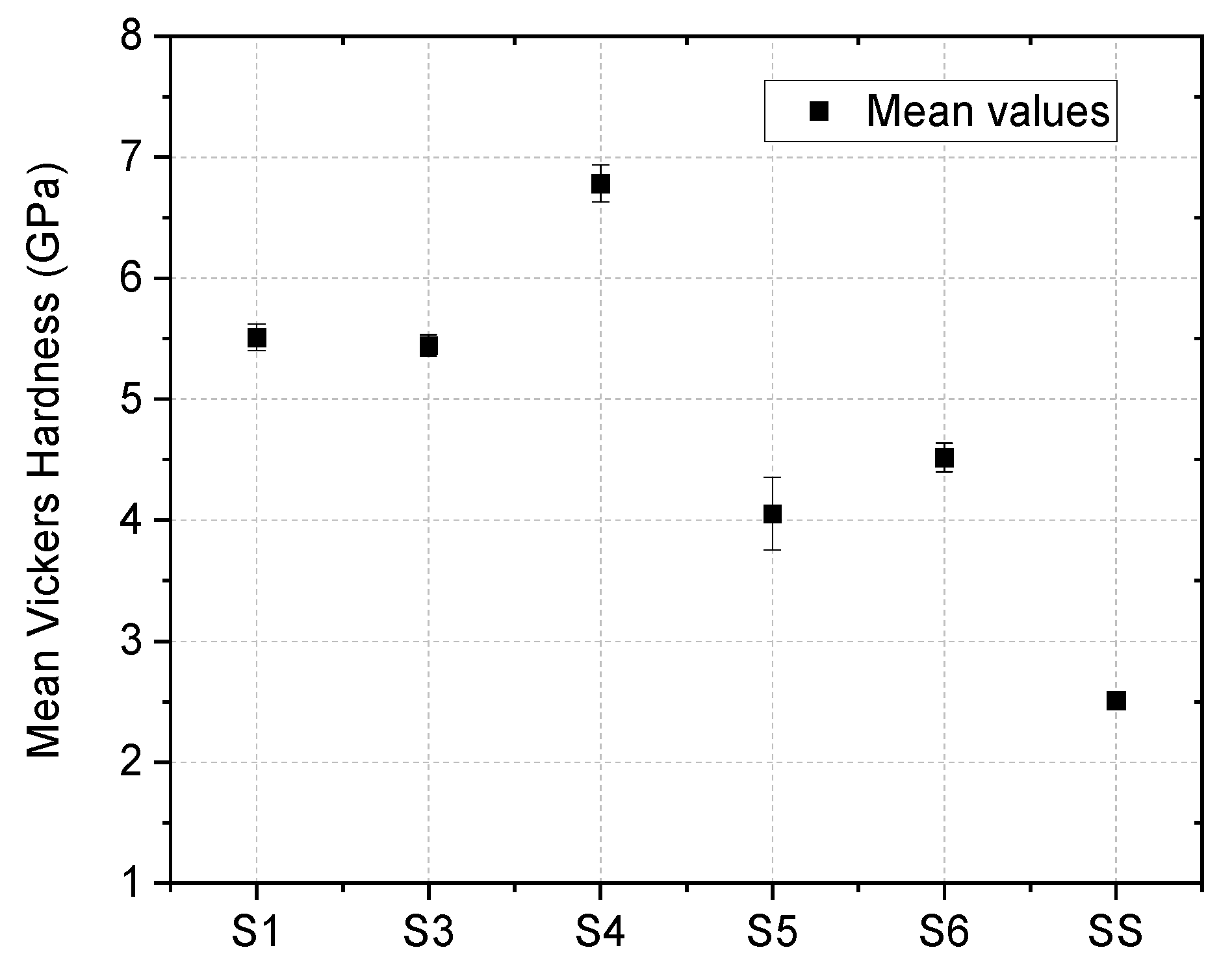
3.3. Mechanical Characterization

After instrumented indentation measurements the indentation hardness (HIT), indentation modulus (EIT), and H/E ratio (deformation relative to yielding) were obtained (Figure 9). The H/E ratio provides valid information regarding the expected tribological behavior. The coating failure could be delayed using redistribution of the applied load if the material expresses high HIT and low EIT [50]. Therefore, sample S4 should behave better in terms of wear resistance and low breakage yield. Similar nanoindentation results were reported for S1 [33] and S4 [51].
The mean Vickers microhardness results are presented in Figure 10. For the deposited samples, the results can be affected by the measuring conditions, the precision of the reading diagonal value (±0.1 µm) of the impression, topology, and thickness of the analyzed sample. Considering the influence of the substrate which might affect the results, due to the indentation depth being larger than 10% of the film thickness, the changes in hardness behavior were reported to the SS substrate. The indenter imprint depth (D) and the thickness (Τ) of the deposited samples must satisfy D < T [52]. For a Vickers indenter, D can be expressed as D ≈ d/7, where d represents the mean value of the imprint diagonals. For all our samples, this condition was satisfied. Taking this into account, up to 10 measurements per sample were performed at different locations on the surface, and the results are presented with the mean standard deviation. The changes in hardness behavior were observed compared to the SS substrate hardness. The maximum hardness value was obtained for the S4 sample, thereby confirming the instrumented indentation results. In the case of co-deposited films, it can be observed how the microhardness values have tendency toward lower values compared to the pure oxides.
Scratch tests and tribological measurements were conducted to determine the adhesion to the substrate characteristics and the wear behavior of the bulk and co-deposited oxide-metal coatings. Figure 11 exhibits the scratch marks produced by the Rockwell type diamond tip for the measured samples over a predefined distance. In the case of S1 and S3 samples, one observes a wedging spallation pattern while high areas of delaminated substrate appear near the indenter mark. For S4 and S5, a buckling pattern was observed, which is related to the propagation of interfacial cracks [53]. The microscratch patterns were analyzed in terms of the representative loads for the appearance of the first cracks, the first delamination and over 50% delamination (Figure 12). The critical loads, especially the ones responsible for the total delamination of the coatings, seem to follow the same pattern from the instrumented indentation results, sample S4 exhibiting the highest critical loads as well as the highest hardness, followed by samples S3 and S5.
Figure 13 presents the variation of the dynamic friction coefficient as a function of the test distance. One can observe that over the first 1–2 m, the friction coefficient presents a high variation before entering in a stable value, with the initial period of instability being referred to as the “break-in” interval. Based on the slope of these curves, it can be seen that sample S3 exhibits the best wear behavior. A comparable gradual increase in the CoF was observed for S4:S5 configurations. S3 expressed a stable CoF compared to S1 having a gradual increase over the sliding distance.

4. Conclusions

Several conclusions can be drawn from the present work:
  • The resulted roughness determined by AFM measurements in Al2O3 metallic-oxides is increased to an extent that could favor gaseous trapping, while co-depositions with Be seem to promote an increased roughness and defects formation probability compared to W co-depositions.
  • XPS characterized the co-deposited films as a mixture of oxidized and metallic states of the constituent elements. For the Al-based configurations, the Be presence determined the occurrence of metallic aluminum.
  • Erbium oxide in both stable cubic phase and metastable monoclinic phase, respectively, were observed in pure and with W addition configurations; for pure Al2O3, a metastable κ-Al2O3 crystalline phase was observed, while the addition of W breaks the stability of κ-Al2O3, without significant influence on the structure;
  • Modifications regarding the desorption mechanism were visible between oxide standards and oxide-metal configurations, while the desorption of O2 is mitigated and the bound of N2 peak is increased in the presence of W in the configuration;
  • Lower elastic modulus on metal-oxide co-depositions was observed, while the indentation hardness increased for Be and decreased for W matrix configurations. Significantly better adhesion behavior was observed for pure configurations of oxides, while co-depositions were highly sensitive to premature delamination.
These results assist the selection of appropriate homogeneous, high-purity, compact, and defect-free configurations to be analyzed in future work with laborious thermal stress campaigns followed by measurements of permeation yield.

Author Contributions

M.L.: conceptualization and writing—original draft. C.P.: validation, conceptualization, and supervision. D.C.: data curation, visualization, investigation, and supervision. C.S.: data curation and investigation. O.G.P.: validation, resources, and methodology. F.B., B.B., C.L. and A.M.: data curation, visualization, and investigation. All authors have read and agreed to the published version of the manuscript.

Funding

This research was funded by a grant of the Ministry of Research, Innovation, and Digitization, CNCS/CCCDI—UEFISCDI, Project Number PN-III-P1-1.1-PD-2019-0745, within PNCDI III; Part of this work was supported by a grant of the Romanian Ministry of Education and Research, CNCS—UEFISCDI, Project Number PN-III-P1-1.1-TE-2019-1209, within PNCDI III.

Institutional Review Board Statement

Not applicable.

Informed Consent Statement

Not applicable.

Data Availability Statement

Not applicable.

Conflicts of Interest

The authors declare no conflict of interest. The funders had no role in the design of the study; in the collection, analyses, or interpretation of data; in the writing of the manuscript, or in the decision to publish the results.

References

  1. Nougués, J.M.; Feliu, J.A.; Campanyà, G.; Iraola, E.; Batet, L.; Sedano, L. Advanced tools for ITER tritium plant system modeling and design. Fus. Sci. Technol. 2020, 76, 649–652. [Google Scholar] [CrossRef]
  2. Hassanein, A.; Sizyuk, V. Potential design problems for ITER Fus. device. Sci. Rep. 2021, 11, 1–11. [Google Scholar]
  3. Poitevin, Y.; Boccaccini, L.V.; Zmitko, M.; Ricapito, I.; Salavy, J.-F.; Diegele, E.; Gabriel, F.; Magnani, E.; Neuberger, H.; Lässer, R.; et al. Tritium breeder blankets design and technologies in Europe: Development status of ITER test blanket modules, test & qualification strategy and roadmap towards DEMO. Fus. Eng. Des. 2010, 85, 2340–2347. [Google Scholar]
  4. Nemanič, V. Hydrogen permeation barriers: Basic requirements, materials selection, deposition methods, and quality evaluation. Nuclear Mater. Energy 2019, 19, 451–457. [Google Scholar] [CrossRef]
  5. Rudomilova, D.; Prošek, T.; Salvetr, P.; Knaislova, A.; Novak, P.; Kodym, R.; Schimo-Aichhorn, G.; Muhr, A.; Duchaczek, H.; Luckeneder, G. The effect of microstructure on hydrogen permeability of high strength steels. Mater. Corrosion. 2020, 71, 909–917. [Google Scholar] [CrossRef]
  6. Wang, L.; Ye, X.; Feng, Y.; Luo, X.; Hong, Z.; Yan, J.; Gong, B.; Liao, H.; Wang, X.; Zhu, C.; et al. Hydrogen isotope permeability of reduced activation ferritic/martensitic steel CLF-1 corroded by Li4SiO4. Fus. Eng. Des. 2020, 153, 111490. [Google Scholar] [CrossRef]
  7. Itakura, A.N.; Miyauchi, N.; Murase, Y.; Yakebe, T.; Kitijima, M.; Aoyagi, S. Model of local hydrogen permeability in stainless steel with two coexisting structures. Sci. Rep. 2021, 11, 8553. [Google Scholar] [CrossRef] [PubMed]
  8. Tanabe, T. Selection of Plasma-Facing Materials. Plasma-Material Interactions in a Controlled Fusion Reactor; Springer: Singapore, 2021; pp. 187–197. [Google Scholar] [CrossRef]
  9. Kim, Y.; Lee, K.H.; Kim, E.-P.; Cheong, D.-I.; Hong, S.H. Fabrication of high temperature oxides dispersion strengthened tungsten composites by spark plasma sintering process. Int. J. Refract. Met. Hard Mater. 2009, 27, 842–846. [Google Scholar] [CrossRef]
  10. Xia, M.; Yan, Q.Z.; Xu, L.; Zhu, L.; Guo, H.; Ge, C. Synthesis of TiC/W core–shell nanoparticles by precipitate-coating process. J. Nucl. Mater. 2012, 430, 216–220. [Google Scholar] [CrossRef]
  11. Li, F.; Chen, C.; Guo, D.; Zhou, X.; Chen, Y.; Long, Y.; Guo, L.; Li, L.; Ren, Q.; Liao, Y.; et al. Rate theory and experimental study of the irradiation induced defects in molybdenum alloy. J. Alloys Compd. 2021, 874, 159751. [Google Scholar] [CrossRef]
  12. Hirai, T.; Pintsuk, G. Thermo-mechanical calculations on operation temperature limits of tungsten as plasma facing material. Fus. Eng. Des. 2007, 82, 389–393. [Google Scholar] [CrossRef]
  13. Zabihi, M.; Toroghinejad, M.R.; Shafyei, A. Application of powder metallurgy and hot rolling processes for manufacturing aluminum/alumina composite strips. Mater. Sci. Eng. A 2013, 560, 567–574. [Google Scholar] [CrossRef]
  14. Rajkovic, V.; Bozic, D.; Jovanovic, M.T. Effects of copper and Al2O3 particles on characteristics of Cu-Al2O3 composites. Mater. Des. 2010, 31, 1962–1970. [Google Scholar] [CrossRef]
  15. Seevakan, K.; Manikandan, A.; Devendran, P.; Slimani, Y.; Baykal, A.; Alagesan , T. Structural, magnetic and electrochemical characterizations of Bi2Mo2O9 nanoparticle for supercapacitor application. J. Magn. Magn. Mater. 2019, 486, 165254. [Google Scholar] [CrossRef]
  16. Slimani, Y.; Almessiere, M.A.; Shirsath, S.E.; Hannachi, E.; Yasin, G.; Baykal, A.; Ozccelik, B.; Ercan, I. Investigation of structural, morphological, optical, magnetic and dielectric properties of (1-x) BaTiO3/xSr0.92Ca0.04Mg0.04Fe12O19 composites. J. Magn. Magn. Mater. 2020, 510, 166933. [Google Scholar] [CrossRef]
  17. Hannachi, E.; Slimani, Y.; Alqwairi, F.; Almessiere, M.A.; Alqwairi, F. Comparative study of thermal fluctuation induced conductivity in YBa2Cu3O7-d containing Nano-Zn0.95Mn0.05O and Nano-Al2O3 particles. Sol. State Sci. 2020, 105, 106264. [Google Scholar] [CrossRef]
  18. Wang, C.; Zhang, L.; Wei, S.; Pan, K.; Wu, X.; Li, Q. Preparation, microstructure, and constitutive equation of W-0.25 wt% Al2O3 alloy. Mater. Sci. Eng. A 2019, 744, 79–85. [Google Scholar] [CrossRef]
  19. Katayama, K.; Ushida, H.; Matsuura, H.; Fukada, S.; Goto, M.; Nakagawa, S. Evaluation of tritium confinement performance of alumina and zirconium for tritium production in a high-temperature gas-cooled reactor for fusion reactors. Fus. Sci. Technol. 2015, 68, 662–668. [Google Scholar] [CrossRef]
  20. Blagoeva, D.; Opschoor, J.; Van der Laan, J.; Sârbu, C.; Pintsuk, G.; Jong, M.; Bakker, T.; Ten Pierick, P.; Nolles, H. Development of tungsten and tungsten alloys for DEMO divertor applications via MIM technology. J. Nucl. Mater. 2013, 442, S198–S203. [Google Scholar] [CrossRef]
  21. Fave, L.; Pouchon, M.A.; Döbeli, M.; Schulte-Borchers, M.; Kimura, A. Helium ion irradiation induced swelling and hardening in commercial and experimental ODS steels. J. Nucl. Mater. 2014, 445, 235–240. [Google Scholar] [CrossRef]
  22. Brimbal, D.; Miro, S.; de Castro, V.; Poissonnet, S.; Trocellier, P.; Serruys, Y.; Beck, L. Application of raman spectroscopy to the study of hydrogen in an ion irradiated oxide-dispersion strengthened Fe–12Cr steel. J. Nucl. Mater. 2014, 447, 179–182. [Google Scholar] [CrossRef]
  23. Chen, J.; Jung, P.; Henry, J.; de Carlan, Y.; Sauvage, T.; Duval, F.; Barthe, M.; Hoffelner, W. Irradiation creep and microstructural changes of ods steels of different cr-contents during helium implantation under stress. J. Nucl. Mater. 2013, 437, 432–437. [Google Scholar] [CrossRef]
  24. Huang, Z.; Harris, A.; Maloy, S.A.; Hosemann, P. Nanoindentation creep study on an ion beam irradiated oxide dispersion strengthened alloy. J. Nucl. Mater. 2014, 451, 162–167. [Google Scholar] [CrossRef]
  25. Lazauskas, T.; Kenny, S.D.; Smith, R.; Nagra, G.; Dholakia, M.; Valsakumar, M. Simulating radiation damage in a bcc Fe system with embedded yttria nanoparticles. J. Nucl. Mater. 2013, 437, 317–325. [Google Scholar] [CrossRef] [Green Version]
  26. Liu, R.; Xie, Z.; Fang, Q.; Zhang, T.; Wang, X.; Hao, T.; Liu, C.; Dai, Y. Nanostructured yttria dispersion-strengthened tungsten synthesized by sol–gel method. J. Alloys Compd. 2016, 657, 73–80. [Google Scholar] [CrossRef]
  27. Odette, G.; Alinger, M.; Wirth, B. Recent developments in irradiation-resistant steels. Annu. Rev. Mater. Res. 2008, 38, 471–503. [Google Scholar] [CrossRef]
  28. Zhang, G.; Wang, X.; Xiong, Y.; Shi, Y.; Song, J.; Luo, D. Mechanism for adsorption, dissociation and difusion of hydrogen in hydrogen permeation barrier of α-Al2O3: A density functional theory study. Int. J. Hydrogen Energy 2013, 38, 1157–1165. [Google Scholar] [CrossRef]
  29. Li, Q.; Wang, J.; Xiang, Q.-Y.; Yan, K.; Yao, W.-Q.; Cao, J.-L. Study on influence factors of permeation reduction factor of Al2O3-hydrogen isotopes permeation barriers. Int. J. Hydrogen Energy 2016, 41, 4326–4331. [Google Scholar] [CrossRef]
  30. Yanan, S.; Xiang, H.; Dai, F.-Z.; Wang, X.; Yan, X.; Zhou, Y. Preparation and properties of CMAS resistant bixbyite structured high-entropy oxides RE2O3 (RE = Sm, Eu, Er, Lu, Y, and Yb): Promising environmental barrier coating materials for Al2O3f/Al2O3 composites. J. Adv. Ceram. 2021, 10, 596–613. [Google Scholar] [CrossRef]
  31. Mohammadtaheri, M.; Yang, Q.; Li, Y.; Corona-Gomez, J. The effect of deposition parameters on the structure and mechanical properties of chromium oxide coatings deposited by reactive magnetron sputtering. Coatings 2018, 8, 111. [Google Scholar] [CrossRef] [Green Version]
  32. Prashant Singh, P.; Kumar Jha, R.; Kumar Singh, R.; Singh, B.R. Preparation and characterization of Al2O3 film deposited by RF sputtering and plasma enhanced atomic layer deposition. J. Vacuum Sci. Technol. B 2018, 36, 04G101. [Google Scholar] [CrossRef]
  33. Huang, Y.; Chen, L.; Jia, X.; Shao, M.; Shao, S.; Zhu, X.; An, K.; Liu, J.; Wei, J.; Li, C. Microstructure, hardness and optical properties of Er2O3 films deposited on diamond-coated and Si(100) substrates by radio frequency magnetron sputtering. Thin Sol. Films 2020, 709, 138131. [Google Scholar] [CrossRef]
  34. Xu, H.; Alfrod, C.; Chason, E.; Detor, A.J.; Fuller, T.; Hamza, A.V.; Hayes, J.; Moreno, K.A.; Nikroo, A.; van Buuren, T.; et al. Thick beryllium coatings by ion-assisted magnetron sputtering. J. Mater. Res. 2012, 27, 22–828. [Google Scholar] [CrossRef]
  35. Bouziane, K.; Mamor, M.; Meyer, F. DC magnetron sputtered tungsten: W film properties and electrical properties of W/Si Schottky diodes. Appl. Phys. A 2005, 81, 209–215. [Google Scholar] [CrossRef]
  36. Nemanič, V.; KovačJozef, J.; Lungu, C.; Porosnicu, C.; Zajec, B. Characterization of tungsten films and their hydrogen permeability. J. Vacuum Sci. Technol. 2014, A32, 061511. [Google Scholar] [CrossRef]
  37. Velicu, I.-L.; Ianoş, G.-T.; Porosnicu, C.; Mihăilă, I.; Burducea, I.; Velea, A.; Cristea, D.; Munteanu, D.; Tiron, V. Energy-enhanced deposition of copper thin films by bipolar high power impulse magnetron sputtering. Surf. Coat. Technol. 2019, 359, 97–107. [Google Scholar] [CrossRef]
  38. Oliver, W.C.; Pharr, G.M. Measurement of hardness and elastic modulus by instrumented indentation: Advances in understanding and refinements to methodology. J. Mater. Res. 2004, 19, 3–20. [Google Scholar] [CrossRef]
  39. Zhou, G.; Wang, L.; Wang, X.; Yu, Y.; Mutzke, A. Effect of bias voltage on microstructure and optical properties of Al2O3 thin films prepared by twin targets reactive high power impulse magnetron sputtering. Vacuum 2019, 166, 88–96. [Google Scholar] [CrossRef]
  40. Naveen, A.; Krishnamurthy, L.; Shridhar, T.N. Thickness and surface roughness study of co-sputtered nanostructured alumina/tungsten (Al2O3/W) thin films. AIP Conf. Proc. 2018, 1943, 020083. [Google Scholar]
  41. Engelhart, W.; Dreher, W.; Eibl, O.; Schier, V. Deposition of alumina thin film by dual magnetron sputtering: Is it γ-Al2O3? Acta Mater. 2011, 59, 7757–7767. [Google Scholar] [CrossRef]
  42. Moulder, F.; Stickle, W.F.; Sobol, P.E.; Bomben, K.D. Handbook of x-ray photoelectron spectroscopy. Phys. Electron. 1995, 230–232. [Google Scholar]
  43. NIST X-ray Photoelectron Spectroscopy Database, NIST Standard Reference Database Number 20; National Institute of Standards and Technology: Gaithersburg, MD, USA, 2000; p. 20899. [CrossRef]
  44. Armelao, L. Silica-Supported Erbium-based Nanosystems: An XPS Characterization. Surf. Sci. Spectra 2004, 11, 26–32. [Google Scholar] [CrossRef]
  45. Armelao, L.; Barreca, D.; Bottaro, G. ZnO:Er(III) Nanosystems Analyzed by XPS. Surf. Sci. Spectra 2006, 13, 9–16. [Google Scholar] [CrossRef]
  46. Adelhelm, C.; Pickert, T.; Balden, M.; Rasinski, M.; Plocinski, T.; Ziebert, C.; Koch, F.; Maier, H. Monoclinic B-phase erbium sesquioxide (Er2O3) thin films by filtered cathodic arc deposition. Scripta Mater. 2009, 61, 789–792. [Google Scholar] [CrossRef] [Green Version]
  47. Yan, D.; Wu, P.; Zhang, S.P.; Liang, L.; Yang, F.; Pei, Y.L.; Chen, S. Assignments of the Raman modes of monoclinic erbium oxide. J. Appl. Phys. 2013, 114, 193502. [Google Scholar] [CrossRef]
  48. Hochauer, D.; Mittere, C.; Penoy, M.; Michotte, C.; Martinz, H.P.; Kathrein, M. Thermal stability of doped CVD κ-Al2O3 coatings. Surf. Coat. Technol. 2010, 204, 3713–3722. [Google Scholar] [CrossRef]
  49. Zhang, L.; Jiang, H.C.; Liu, C.; Dong, J.W.; Chow, P. Annealing of Al2O3 thin films prepared by atomic layer deposition. J. Phys. D Appl. Phys. 2007, 40, 3707. [Google Scholar] [CrossRef]
  50. Söderlund, E.; Reineck, I.; Rowcliffe, D. Ultralow load indentation hardness and modulus of K—and α–Al2O3 CVD coatings. J. Mater. Res. 1994, 9, 1683–1692. [Google Scholar] [CrossRef]
  51. Ruppi, S.; Larsson, A.; Flink, A. Nanoindentation hardness, texture and microstructure of α-Al2O3 and κ-Al2O3 coatings. Thin Sol. Films 2008, 516, 5959–5966. [Google Scholar] [CrossRef]
  52. Tiron, V.; Porosnicu, C.; Dinca, P.; Velicu, I.-L.; Cristea, D.; Munteanu, D.; Revesz, A.; Stoian, G.; Lungu, C.P. Beryllium thin films deposited by thermionic vacuum arc for nuclear applications. Appl. Surf. Sci. 2019, 481, 327–336. [Google Scholar] [CrossRef]
  53. Broitman, E. Indentation hardness measurements at macro-, micro-, and nanoscale: A critical overview. Tribol. Lett. 2017, 65, 23. [Google Scholar] [CrossRef] [Green Version]
Figure 1. 3D rendering of co-deposition experimental setup where the positions of oxide and metallic targets can be observed; Overview on simultaneous plasma ignition of W (a) and Be (b) with oxides magnetrons.
Coatings 11 01430 g001
Figure 2. 3D AFM images obtained from the samples deposited on Si: S1 (a), S2 (b), S3 (c), S4 (d), S5 (e), and S6 (f).
Coatings 11 01430 g002
Figure 3. RMS surface roughness (nm) determination from 2D AFM images for multiple configurations of thin layer depositions; S6 film expressed the most excreased roughness.
Coatings 11 01430 g003
Figure 4. SEM images of oxides and metal-oxides at 5 k and 10 k × magnification for S1 (a), S2 (b) S3 (c), S4 (d), S5 (e), and S6 (f).
Coatings 11 01430 g004
Figure 5. Al2p XPS superimposed spectra for the three stages of the Al system (a); Al2p XPS peak-fitted spectrum for Al2O3-W system suggesting constant chemical behavior on the higher binding energy side of the Al2p photoemission peak (b); Al2p XPS peak-fitted spectrum for Al2O3-Be system identifying the occurrence of metallic aluminum (c).
Coatings 11 01430 g005
Figure 6. Er4d XPS superimposed spectra for the three stages of the Er system; Er4d spectra indicated an oxidized erbium surface as Er2O3 (168.6 eV).
Coatings 11 01430 g006
Figure 7. XRD analysis of magnetron sputtered layers: S1, S2, S4, and S5; A broad peak was observed for S1 and S2, which corresponds to erbium oxide in stable cubic or metastable monoclinic phase; The κ-Al2O3 crystalline phase is highlighted for S4, while for S5, no diffraction peak could be observed.
Coatings 11 01430 g007
Figure 8. TDS was conducted at a heating rate of 10 °C/min, and spectra were acquired for the following samples: S1 (a), S3 (b), S4 (c), S5 (d), and S6 (e); S2 was negatively affected by the heating process (severe delamination).
Coatings 11 01430 g008
Figure 9. Nanoindentation results; S4 film expresses the highest HIT.
Coatings 11 01430 g009
Figure 10. Vickers microhardness results for HV 0.01 load; S4 film expressing the highest hardness coefficient.
Coatings 11 01430 g010
Figure 11. Coating failure due to scratch tests for S1 (a), S3 (b), S4 (c), and S5 (d); magnified optical images for interfacial failure modes overview where S1 and S3 presented a wedging spallation destructive pattern, while a buckling pattern was observed for S4 and S5.
Coatings 11 01430 g011
Figure 12. Representative loads for the first delamination and over 50% delamination on undoped oxides and metallic oxides films; S2 and S6 configurations presented heavy premature delamination; and S4 presented the highest load until 50% delamination occurred.
Coatings 11 01430 g012
Figure 13. Friction coefficient versus running distance. Smoothed data lines by adjacent averaging function; S3 presented a stable CoF in comparison to S1 that had a progressive increase in relation to the sliding distance.
Coatings 11 01430 g013
Table 1. Samples code name for each configuration and their representative deposition parameters.
Sample Code Name ConfigurationRF
[W]
DCPressure
[10−3 mbar]
Deposition Rate × 10−1 [n/s]
[kV][A]
S1Er2O3100--1.50.6
S2Er2O3:W1000.320.04400.8 (0.6:0.2)
S3Er2O3:Be600.320.04103.4 (0.6:2.8)
S4Al2O3100--30.14
S5Al2O3:W1000.320.0240.16 (0.14:0.028)
S6Al2O3:Be1000.420.1540.44 (0.14:0.3)
Table 2. EDX composition measurements (wt.%/at.%).
SampleErAlOWBe
S184.88/34.93-15.12/65.07--
S253.11/37.73-4.69/34.8842.31/27.41-
S382.15/30.56 17.85/69.44 Not detectable
S4-42.83/30.7657.17/69.24--
S5-18.06/25.4926.49/63.0355.45/11.48-
S6-46.29/33.8353.71/66.17-Not detectable
Table 3. Element relative concentrations (at.%).
SampleO1sAl2pW4fBe1sEr4d
S160.8---39.2
S262.8-2.5-34.7
S358.9--24.616.5
S483.516.5---
S579.213.47.4--
S664.27.9-27.9-
Publisher’s Note: MDPI stays neutral with regard to jurisdictional claims in published maps and institutional affiliations.

