Article

Enhanced Anticorrosion Properties through Structured Particle Design of Waterborne Epoxy-Styrene-Acrylate Composite Emulsion

Hubei Key Laboratory for Processing and Application of Catalytic Materials, School of Chemistry and Chemical Engineering, Huanggang Normal University, Huanggang 438000, China
*
Author to whom correspondence should be addressed.
Coatings 2021, 11(11), 1422; https://doi.org/10.3390/coatings11111422
Submission received: 19 October 2021 / Revised: 16 November 2021 / Accepted: 18 November 2021 / Published: 21 November 2021

Abstract

:
In order to develop a waterborne epoxy-styrene–acrylate composite latex with a better stability and anticorrosion resistance, a novel synthetic approach has been proposed. First, modified by methyl acrylic, epoxy resin containing terminal C=C double bonds was successfully synthesized, where epoxide groups were partially retained. Then, by structural design and multi-stage seed emulsion copolymerization, a stable waterborne epoxy-styrene-acrylate composite latex composed of a modified epoxy resin acrylate polymer as the core, inert polystyrene ester as the intermediate layer, and carboxyl acrylate polymer as the shell was successfully fabricated. The structure of the obtained latex was characterized by fourier transform infrared (FTIR) and transmission electron microscopy (TEM). The stability of the composite latex was tested based on the wet gel weight, Zeta potential, and storage stability, and the corrosion resistance of the composite latex films was analyzed by electrochemical measurements and salt spray tests. The thickness of each layer of the composite latex was calculated by the temperature random multi-frequency modulation DSC (TOPEM-DSC) technique. In addition to the successful emulsion copolymerization that occurred between the modified epoxy resin and acrylate monomer, the presence of carboxyl groups in the obtained latex was evidenced, while the epoxide groups were partially retained. The anticorrosion resistance and stability of the multilayer composite latex with the intermediate layer are better than that of the conventional core-shell latex. The outstanding stability and corrosion resistance is attributed to the multilayer core-shell structure. The TOPEM-DSC approach can accurately determine the thickness of the intermediate layer in the multilayer core-shell particles and is a new strategy for characterizing the core-shell structure of polymer particles with a similar monomer composition.

1. Introduction

With the strict enforcement of laws and regulations for environmental protection, waterborne epoxy resin coatings have attracted much attention. However, waterborne coatings made from epoxy resin alone cannot compete with solvent coatings in terms of performance. Epoxy-acrylate composites possess the merits of both epoxy resin and acrylate resin [1,2]. In the past 30 years, there are two main methods to prepare epoxy-acrylate composites. One is physical blending, and the other is chemical modification through a graft reaction or esterification reaction [3,4]. However, due to the spontaneous ring opening of the epoxide group in the process of polymerization and during storage or the easy hydrolysis of ester groups, the stability of the composite is not good [5,6]. In addition, due to the depletion of the epoxide group, the coating resistance of the resulting film is also not good [7].
In recent years, waterborne epoxy-acrylate composites are mostly prepared by an emulsion polymerization. Wang et al. [8] demonstrated the synthesis of styrene acrylic-epoxy composite latex by conventional emulsion polymerization, where the utilization of organic solvents for the formation of a water-reducible epoxy-acrylic copolymer was excluded. A damping material based on a core-shell-structured epoxy-acrylate composite was synthesized by Tang et al. [9] through conventional emulsion polymerization. However, in conventional emulsion polymerization, it is difficult to have a large amount of the epoxy resin incorporated into the composite due to the hydrophobicity of epoxy resin. To solve the problem, mini-emulsion polymerization has been recently adopted to incorporate or graft epoxy resin into acrylate emulsion [10,11,12]. Moreover, an epoxy-acrylate (EP-AC) composite latex with a high EP content was prepared by mini-emulsion polymerization for anticorrosion coatings by Yao et al. [13]. By adding a crosslinking agent during film formation, the anticorrosion properties of the composite coatings were remarkably improved. In a surfactant and co-surfactant co-functionalized system, Tang et al. [14] prepared a composite latex with a high content of epoxy-styrene-acrylate for metal coating via a mini-emulsion grafting method. However, the two polymers physically combined during preparation. Woo and Toman [3] reported that hydrogen could be captured on the backbone of the epoxy resin chain by the initiator under solvent conditions, whereby the grafting of the acrylate monomer cannot be initiated in emulsion conditions. All of the above-mentioned factors make the fabrication of a film with a stable and superior performance challenging.
Nevertheless, the difficulties could be tackled by improving the reactivity of the hydrophobic epoxy resin with the acrylate monomer under the emulsion situation. Duan et al. [15] synthesized a binder resin by having epoxy resin modified with methyl acrylic acid (MA) and then copolymerizing the modified epoxy resin with several acrylic monomers via free radical polymerization. However, due to the reaction between the epoxied groups of modified epoxy resin and the carboxyl groups of acrylic monomers, gel formation could occur. More recently, our group synthesized a new epoxy acrylic oligomer containing a vinyl group through an epoxy resin reaction with acrylic acid in a controlled manner, where epoxide groups were partially retained. This led to the successful generation of an epoxy-acrylate composite emulsion [16]. Although the oligomeric monomer was placed in the core of a core-shell particle, where the shell was an acrylic polymer, the epoxide in the oligomeric monomer survived the reaction with carboxylic functional monomers in the shell. In other words, the conflict between the stability and self-crosslinking controllability of the epoxy-acrylate composite latex still exists to a certain extent.
With the development and application of particle design theory, the preparation of latex particles with a multilayer structure has become a research hotspot [17,18,19,20]. This type of polymer can be produced by multistage emulsion polymerization, where there is a growth of previously formed seeds upon the addition of monomer(s), hence avoiding the need to form new particles. It was reported that multilayer polymers could have different mechanical behaviors despite being equal in their overall composition [21]. Song et al. [22] developed a new tactic to prepare a multi-layer core-shell poly(siloxane)/polystyrene/polymethyl methacrylate (PSi/PSt/PMMA) latex, which has wide applications in the production of coatings, as well as modified polymer materials. A kind of epoxy-acrylate emulsion with a three-layer core-shell structure and different contents of epoxy resin was synthesized by Liu et al. [17], and the film with the 30 wt.% epoxy content had the characteristic of self-stratification. However, because the core was prepared as an epoxy emulsion by phase inversion, the concentration of the emulsifier was as high as 12 wt.% of the monomers. Moreover, Foster et al. [23] developed a structured three-layer acrylate-based latex that comprises a core with a composition that was identical across the particles, a crosslinked interlayer between the core and shell, and a shell that contained reactive groups for interfacial crosslinking between particles during film formation upon the addition of the crosslinking agent. In addition, Deplace et al. [24] demonstrated that it is feasible to effectively compartmentalize the phases and have them discretely located within the particles by designing properly structured latexes.
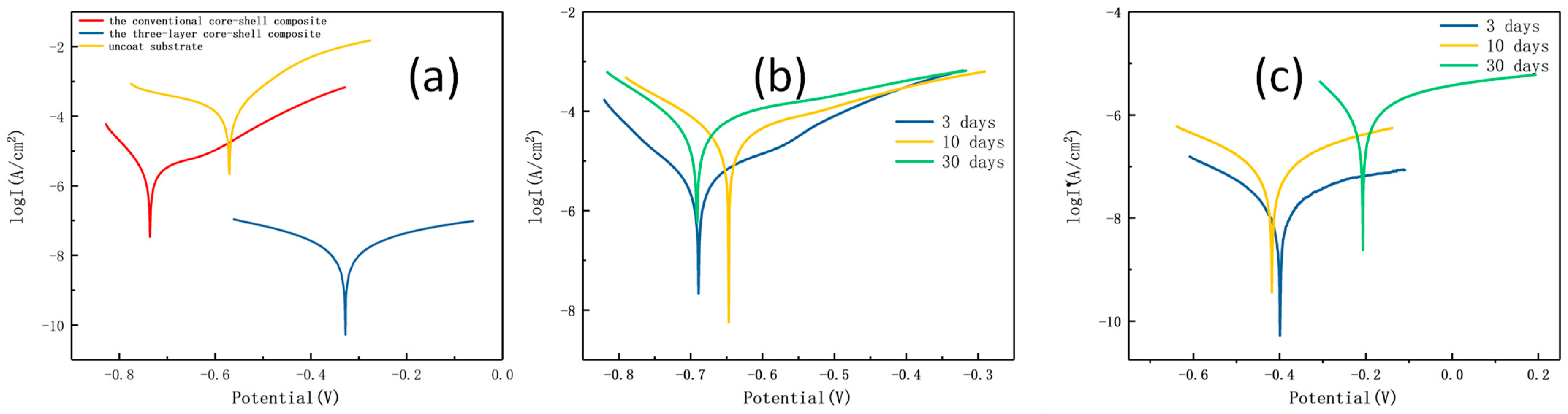
Although waterborne epoxy coatings have been commercialized for more than 40 years, they only share a small percentage of the total market of anticorrosive coatings because their anticorrosion performance is much inferior to that of solvent coatings [25]. Generally, the paint industry solves the problem by repeating the application several times, which is not only cost demanding and time consuming, but also results in an undesirable increase in the coating thickness. To improve the intrinsic anticorrosion properties of waterborne coatings, it is recommended to introduce various additives and/or anticorrosive pigments into the coating formula [26]. Recent innovation in nanotechnology has pushed waterborne epoxy coatings toward the direction of barrier improvement [27,28,29,30]. However, it is hard to achieve a satisfactory dispersity and compatibility between the inorganic phase and polymer. It was demonstrated that enabling self-crosslinking through a structured particle design is a workable way to enhance the anticorrosion properties of waterborne epoxy acrylate composites [31,32,33].
In theory, the reaction of functional groups between the core and shell during polymerization and storage can be avoided by setting an intermediate layer as a barrier between the core and shell by structural design. However, the key factor is whether the intermediate layer is strong enough to maintain its integrity when subjected to the tension of core-shell expansion [34,35]. If the intermediate layer is too thin, it is easy to break, and the composite emulsion is unstable during polymerization or storage. If it is too thick, the polymer chains are difficult to diffuse, and there is loss of self-crosslinking ability [36]. Therefore, the design of an intermediate layer with an appropriate thickness is of great significance for the development of waterborne epoxy-acrylate composite latex with stability and a self-crosslinking ability. To the best of our knowledge, so far, there has been no research on this topic.
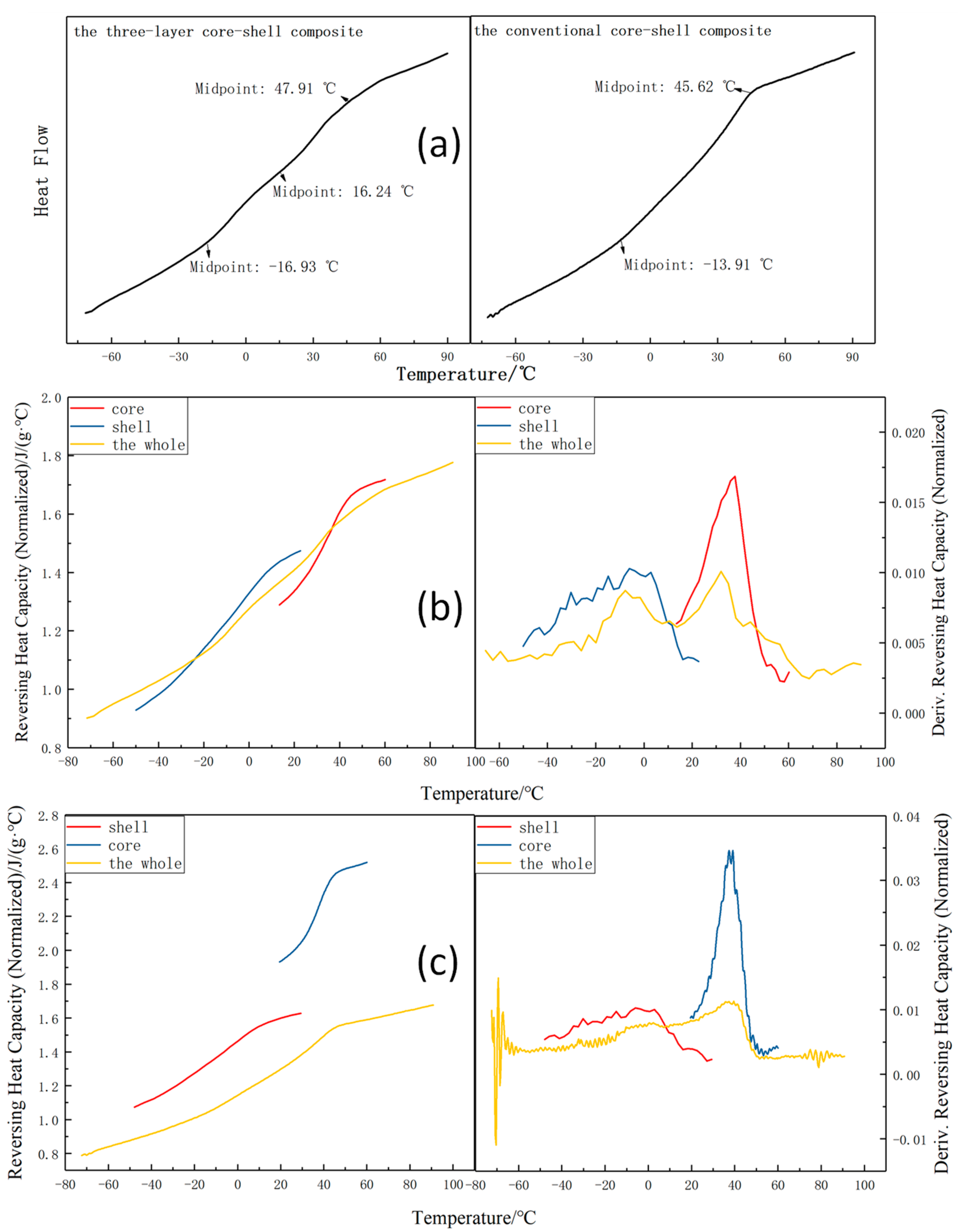
The methods for the morphological characterization of multilayer core-shell-structured latex particles mainly include transmission electron microscopy (TEM), scanning electron microscopy (SEM), and atomic force scanning electron microscopy (AFM) [37]. TEM is the most used, but it is not capable of differentiating the structures of polymer latex particles that have a similar monomer composition. Temperature random multi-frequency-modulated differential scan calorimetry (TOPEM-DSC) adopts a slow heating rate and a fast instantaneous heating rate in order to achieve the combination of high sensitivity and high resolution. At the same time, the total heat flow is divided into reversible heat flow and irreversible heat flow, so the technique can measure the reversible heat flow independent of the frequency. Duan et al. [38] synthesized a two-layer core-shell-structured styrene-acrylic emulsion, quantitatively studied the phase structure of core-shell emulsion particles by TOPEM-DSC, and found that there is an interface layer between the core and shell. In addition, Zahedi et al. [39] synthesized a core/shell/shell acrylate emulsion by multi-stage polymerization and characterized the glass transition temperature of each phase by the TOPEM-DSC technique. However, the TOPEM-DSC technique has not been applied to study the actual thickness of interlayer.
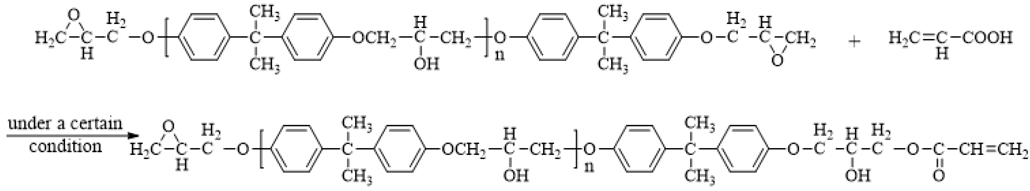
In the present study, a three-layer core-shell-structured waterborne epoxy-styrene-acrylate composite was prepared by multi-stage seed emulsion polymerization. The novelty is to prepare the composite latex by structural design in order to achieve stability and the self-crosslinking of waterborne epoxy resin simultaneously, in which, an inert intermediate layer of the styrene-acrylate copolymer is set between the inner core (with the acrylate polymer containing epoxied groups) and outer shell (with the acrylate polymer containing carboxyl groups). In addition, the effects of the inert intermediate layer on the stability of the composite emulsion and the corrosion resistance of the composite films were investigated. Most significantly, the method using the TOPEM-DSC technique to characterize the application of a multilayer core-shell emulsion for the construction of a latex particle structure has been demonstrated.

2. Experimental

2.1. Materials

Diglycidylether of bisphenol-Aliquid epoxy resin (E-44) was supplied by Guangzhou Dongfeng Chemicals Co., Ltd, Guangzhou, China. Methyl acrylic acid (MAA), acrylic acid (AA), methyl methacrylate (MMA), n-butyl acrylate (BA), and styrene (St) monomers were obtained from Guangzhou Langri Chemical Co. Ltd., Guangzhou, China. Technical grade surfactant sodium dodecyl biphenyl ether sulfonate (DSB), ethoxyalkyl phenolic ammonium sulfate (CO-436), and polyoxyethyleneoctyl phenol ether (OP-10) were purchased from Carpoly Chemical Group Co., Ltd., Jiangmen, China. Analytical grade potassium persulfate (KPS), sodium hydrogen carbonate (NaHCO3), hydroquinone, and N,N-dimethylformamide (DMF) were obtained from Guangzhou Chemicals Factory, Guangzhou, China.

2.2. Preparation of Acrylic-Modified Epoxy Resin

Acrylic-modified epoxy resin containing vinyl groups, and with partial retention of epoxy groups, was synthesized by the esterification of epoxy resin with acrylic acid following the typical process detailed elsewhere [16]. The modified epoxy resin was synthesized by the reaction of E-44 with AA monomers at a molar ratio of 1:1, as depicted in Figure 1. A certain amount of hydroquinone and N,N-dimethylformamide was used as inhibitor and catalyst, respectively. The reaction was maintained at 75 °C for 30 min, and then the temperature was increased to 80 °C and maintained for a certain period of time until its acid value was less than 0.03 mg/g.

2.3. Preparation of Three-Layer Core-Shell-Structured Waterborne Epoxy-Styrene-Acrylate Composite Latex

It was reported that the instantaneous composition of copolymer is governed by the composition of monomer feed. The reaction was carried out in a semi-continuous mode at starved conditions, where the rate of monomer addition was lower than the rate of reaction. The structured three-layer epoxy-styrene-acrylate composites comprise a core made of modified epoxy resin acrylate polymer with epoxide groups, an inert interlayer made of styrene-acrylate polymer, and a shell that contains carboxyl acrylate polymer. The composite was prepared by multi-stage seeded semi-continuous emulsion polymerization using a four-necked round-bottom flask of 500 mL equipped with a mechanical stirrer, condenser, and thermometer, and the detailed information of the reaction formula is presented in Table 1.
First, the backing materials were dropped into the flask under vigorous stirring, and the temperature was increased to 80 °C. Meanwhile, the emulsifier solution, part of the monomer mixtures (10 wt.% of total monomer weight), and deionized water were pre-emulsified and added to the reaction flask at a constant rate through a constant peristaltic pump within 15 min to obtain a seed emulsion. The seed emulsion was kept at 80 °C for 10 min, and, at the same time, the core monomers and initiator solution were dropped into the reaction flask through a constant peristaltic pump. The reaction temperature was kept at 80 °C within 2 h of addition, and then maintained at 80 °C for another 20 min, and the formation of core particles occurred at this stage. Then, the transition monomer and the remaining core initiator were dropwise added within a period of approximately 1 h. After heat preservation for 20 min, the formation of the intermediate layer occurred. Finally, the shell monomers and initiator solution were dropped into the reaction flask via a constant peristaltic pump at 80 °C within 2 h. Afterwards, the reaction temperature was increased to 85 °C for an additional period of 30 min to obtain the three-layer core-shell epoxy-styrene-acrylate composite emulsion (denoted hereinafter as “three-layer core-shell emulsion”). A schematic of its preparation is shown in Figure 2. For comparison, conventional core-shell emulsion was prepared by the same method (denoted hereinafter as “conventional core-shell emulsion”). The only difference is that the transition monomer was mixed with the core monomer before dropwise addition.

2.4. Characterization

Fourier transform infrared (FTIR) analysis of modified epoxy and epoxy-styrene-acrylate composite latex films was conducted on a Nicolet 6700 spectrometer (Antaris, Waltham, MA, USA). Transmission electron microscopy (TEM, Hitachi, Tokyo, Japan) images of the latex particles were taken by using a field emission TEM at 80 kV (HITACHI H-7650). The glass transition temperature and specific heat capacity of the dried latex was measured by differential scanning calorimetry (DSC 25, TA, New Castle, Pennsylvania, USA) at multi-frequency temperature-modulated conditions under nitrogen atmosphere with a heating/cooling rate of 2 °C/min and modulation amplitude of ±0.5 °C in the −80–100 °C range. Measurements of particle size and Zeta potential were performed via a dynamic light-scattering (DLS) analyzer (NanoBrook90 Plus, Brookhaven, Holtsville, New York, NY, USA). The corrosion analysis of coating samples was investigated by potentiodynamic polarization (PDP) and electrochemical impedance spectroscopy (EIS) technique using a CHI660E electrochemical workstation (Chenhua, Shanghai, China). All of the electrochemical tests were performed in 3.5 wt.% NaCl solution. A typical three-electrode system was employed in this test set up, with coated samples as working electrode (7068 cm2 exposed area), saturated Ag/AgCl electrode as reference electrode, and graphite as counter electrode. The polarization curves were recorded from −250 to +250 mV versus open circuit potential (OCP) at a scan rate of 1 mV/s. All of the EIS experiments were carried out in the frequency range of 0.01–105 Hz and applied voltage of 0.01 V. All of the tests were performed at room temperature (298 K). Salt spray test was performed for 400 h in a YWX/Q-250 salt mist chamber (Emerson Instruments Ltd., Shanghai, China) with 5 wt.% NaCl solution at 90% humidity according to the ISO 9227-2012 [40].

3. Results and Discussion

3.1. Method for the Determination of Intermediate Layer Thickness

According to the TOPEM-DSC curve of specific heat capacity, the specific heat tolerance ΔC_p at Tg is directly calculated by “TOPEM evaluation” software (TRIOS 4.4.0.41651). The weight fractions of the intermediate regions were calculated based on the principle of (1)–(4) below [38], according to the assumption that (i) the three-layer core-shell particle is rigid and spherical, which contains three layers: core phase, intermediate layer, and shell phase, (ii) in a layer upon layer manner, each layer has the same density, and (iii) the interfacial regions are located just between the core and the intermediate layer, as well as between the intermediate layer and the shell, as depicted in Figure 3 in blue.
ΔC_pw = ΔC_pc + ΔC_pi + ΔC_ps
ω_c = ΔC_pc/ΔC_pc0
ω_s = ΔC_ps/ΔC_ps0
ω_i = 1 − ω_c − ω_s
where ΔC_pw is the sum of the heat tolerance for the whole latex particle at Tg; ΔC_pc, ΔC_pi, and ΔC_ps are the ΔC_p for the core phase, intermediate phase, and shell phase of the latex particle at their corresponding Tg, respectively; ΔC_pc0 and ΔC_ps0 are the ΔC_p at Tg for the pure core polymer and shell polymer latex, respectively; ω_c, ω_i, and ω_s are the weight fractions of the core, intermediate, and shell layer of the latex, respectively. The calculation was addressed as follows (5)–(8):
4 3 R c 3 = ω c 4 3 ( R c + R i + R s ) 3
R c R c + R i 4 r 2 dr = ω i 4 3 ( R c + R i + R s ) 3
R c + R i R c + R i + R s 4 r 2 dr = ω s 4 3 ( R c + R i + R s ) 3
R c + R i + R s = R
where Rc, Ri, and Rs are the radius of the core phase, the thickness of the intermediate layer, and the thickness of the shell phase, respectively. After simplification, one can obtain the formula:
R c = ω c 3   R
R i = ( ω i + ω c   3 ω c   3 ) R
R s = ( 1 ω i + ω c 3 ) R
According to Formula (9)–(11), the radius of the core phase Rc, the thickness of the intermediate layer Ri, and the thickness of the shell Rs can be calculated, respectively. The calculated Ri includes the set intermediate layer and the interphase layer.

3.2. FTIR Spectroscopy

The FTIR spectra of the epoxy resin before and after being modified are shown in Figure 4A. By comparison, the characteristic absorption peak of the vinyl, ester carbonyl, and epoxide groups appear at 1670, 1725, and 915 cm−1, respectively. The results indicate that, by reacting the epoxy resin with acrylic acid, the epoxy resin is modified, and its molecular chain contains terminal C=C double bonds and epoxide groups. The FTIR spectra of the conventional core-shell emulsion and three-layer core-shell emulsion (all sample films dried at 20 °C) are shown in Figure 4B. As can be seen, the characteristic absorption peak of the epoxide groups appears at 915 cm−1, and those of the ester carbonyl and carboxylic acid carbonyl groups appear at 1730 and 1610 cm−1, respectively, indicating a successful polymerization between the modified epoxy resin and acrylate monomer. After the polymerization, there is a retention of epoxide groups in the composite. It is noted that the absorption peak at 915 cm−1 of the three-layer core-shell emulsion is more significant than that of the conventional core-shell emulsion. For the former, the 915 cm−1 characteristic signal of the epoxide groups still existed six months after polymerization, whereas, for the latter, the epoxide signal became less significant. It is plausible that, for the three-layer core-shell emulsion, the interaction between the epoxide and carboxylic groups is prevented because of the intermediate layer, leading to an improvement in stability.

3.3. TEM Image of Three-Layer Core-Shell Emulsion

Depicted in Figure 5 are the TEM micrographs of waterborne epoxy-styrene-acrylate composites with unmodified epoxy resin, as well as those of the conventional core-shell and three-layer core-shell structure with epoxy resin modified with acrylic acid. Under the same conditions, the composite prepared from unmodified epoxy resin displays an irregular spherical morphology without any indication of a core-shell structure due to its hydrophobicity and poor reaction with acrylate monomers. As for the composites prepared from the modified epoxy resins, they show a spherical structure (Figure 5b,c) because of their facile reaction with the acrylate monomer. Nonetheless, the three-layer core-shell structure was not observable (Figure 5c), plausibly owing to the similarity of the monomer composition between the intermediate layer and shell layer.

3.4. Determination of Intermediate Layer Thickness of Three-Layer Core-Shell Emulsion

To identify thermal events, a DSC test was conducted (Figure 6a).
There are three glass transitions for the three-layer core-shell composite, whereas there are only two glass transitions for the conventional core-shell emulsion film. A more detailed structure characterization of the three-layer core-shell emulsion film was conducted by TOPEM-DSC (Figure 6b). For comparison, the conventional core-shell emulsion film was also characterized (Figure 6c). Based on the TOPEM-DSC curves, the specific heat capacity ΔC_p of each phase of the film in the quasi-steady state can be obtained. The mass fraction of each phase can then be calculated by using the formula, and the thickness of each layer of the latex particles can be calculated by combining with the particle size results, as shown in Table 2. As can be seen, the sum of ωc and ωs for the conventional core-shell particle is less than 1, indicating the existence of an interface layer Ri. As a result of the similarity of the monomer composition between the core phase and shell phase, there is inevitable fusion, thus forming the interface layer. The value of Ri of the three-layer core-shell particle is much larger than that of the conventional core-shell particle, indicating that the prepared three-layer particle indeed contains the set intermediate layer, which can separate the core phase from the shell.
To explore the feasibility of the above methods, the particle size at the three stages of emulsion, including the core stage, the transition stage (core-intermediate layer), and the stage at the end of polymerization was tested. The average particle size of each stage is shown in Table 3.
Comparing the data in Table 3 with those in Table 2, the Ri″ of the three-layer core-shell particle detected by the dynamic light scattering (DLS) laser particle size distribution analyzer is smaller than that calculated by TOPEM-DSC, which indicates the existence of an interface layer between the core phase and the intermediate layer, as well as between the intermediate layer and the shell phase. Moreover, the Ri″ of the three-layer core-shell particle measured by DLS is bigger than that of the conventional core-shell particle calculated by TOPEM-DSC, which further indicates that the intermediate layer thickness of the three-layer structure emulsion calculated by TOPEM-DSC does include the set interlayer thickness. In summary, the TOPEM-DSC technique can accurately calculate the thickness of the interlayer layer of the three-layer-structured latex particles.

3.5. Stability of Three-Layer Core-Shell Emulsion

A Zeta potential test and storage stability observation were conducted for the three-layer core-shell emulsion and the conventional core-shell emulsion, and the results are compiled in Table 4. Based on an equal formulation, the former is more stable than the latter. The three-layer core-shell emulsion has a higher Zeta potential upon discharging, and there was no sight of condensate after 6 months. It is hence deduced that the intermediate layer is beneficial for improving the polymerization stability and storage stability of the composite emulsion.

3.6. Corrosion Resistance

3.6.1. Potentiodynamic (PD) Polarization Study

A PD polarization test can be used to evaluate the anticorrosion performance of polymer coatings. Figure 7 exhibits the Tafel polarization curve of uncoated, coated with a conventional core-shell coating, and that with a three-layer core-shell coating after different immersion periods in 3.5% NaCl solution.
The electrochemical parameters, including the corrosion potential (Ecorr), corrosion current density (Icorr), polarization resistance (Rp), corrosion rate (Rcorr), and anode/cathode Tafel slopes (βac), of the coatings are provided in Table 5. For each immersion time interval, it is observed that the Ecorr of the three-layer core-shell coating is higher than that of the conventional core-shell coating, that the Icorr of the three-layer core-shell coating is two orders of magnitude lower than that of the conventional core-shell coating, and that both are much lower than that of the uncoated substrate. Meanwhile, the Rcorr and Rp of the three-layer core-shell coating is nearly two orders of magnitude smaller and three orders of magnitude larger than that of conventional core-shell coating. These results show that, compared to the conventional core-shell coating, the three-layer core-shell coating can provide better protection against corrosion. This is ascribed to the crosslinking network established between the core and shell during film formation and the incorporation of the set interlayer, making it difficult for the corrosive medium to penetrate the coating in order to initiate corrosion on the metal substrate [32].

3.6.2. Electrochemical Impedance Spectroscopy (EIS) Study

The corrosion behaviors of different coatings immersed in 3.5 wt.% NaCl solution at different time periods were monitored by EIS tests using an electrochemical workstation. As shown in Figure 8a, the open circuit potential (OCP) values of the three-layer core-shell coating and the conventional core-shell coating are approximately −0.31 and −0.57 V at initial immersion, respectively. The negative OCP value could be related to the nature of the epoxy resin [25]. With an increase in immersion time, the OCP values of both coatings gradually decrease, which reflects the penetration of the corrosive medium into the coating. However, the decrease in the OCP values of the three-layer core-shell coating is obviously lower than that of the conventional core-shell coating, and the OCP values of the three-layer core-shell coating remain approximately −0.43 V after 30 days of immersion. It is deduced that the three-layer core-shell coating has a better barrier performance than the conventional core-shell coating.
An EIS test was further employed to study the anticorrosion performance of coatings during long term immersion in 3.5 wt.% NaCl solution. The Nyquist plots and Bode plots of the uncoated substrate and the substrate coated with a conventional core-shell composite and a three-layer core-shell composite at initial immersion are shown in Figure 9.
In general, the diameters at high frequencies in the Nyquist plot and the lowest-frequency modulus (|Z|0.01Hz) in the Bode plot for both coatings decrease with an increase in the immersion time. As shown in the Nyquist plot (Figure 9a,c,e), it is clear that the arc radius of the three-layer core-shell coating is larger than that of the conventional core-shell structure coating for each immersion time interval, and that both are much larger than that of the bare substrate. The lowest-frequency impedance modulus (|Z|0.01Hz) is closely related to the corrosion resistance of the coating. Figure 8b shows the change in |Z|0.01Hz with the increase in immersion time. The value of |Z|0.01Hz (3.45 × 10⁶ Ω·cm2) of the three-layer core-shell coating only dropped by an order of magnitude after 10 days and was still 3.81 × 10⁵ Ω·cm2 after 30 days, retaining approximately 80% of the initial impedance. In contrast, the |Z|0.01Hz of the conventional core-shell coating suffered a relatively bigger change (from 1.24 × 10⁴ Ω·cm2 to 4.23 × 10³ Ω·cm2). The above results suggest that both coatings have corrosion protection properties and that the anti-corrosion effect of the three-layer core-shell coating is better than that of the conventional core-shell coating.
In order to further study, three equivalent electrical circuits (EECs) in Figure 10 were used to fit the EIS data using ZSimpWin software (ZSimpWin 3.60), and the values of the impedance parameters extracted from the equivalent models are listed in Table 6.
Model A was applied to the initial immersion stage of both coatings. In this stage, both coatings act as a physical barrier exhibiting an excellent anti-corrosion ability. Model B is suitable for the simulation of the coating/metal interface at the middle corrosion period when there is a uniform penetration of the electrolyte solution through the coating, as well as an even distribution of corrosion sites [32]. Model C was used to stimulate the medium corrosion stage after 3 days of immersion of the one with the three-layer core-shell coating. In this case, a Warburg diffusion slope appeared [41,42]. In the equivalent circuit, Rs, Rc, and Rct are the solution resistance, coating resistance, and the charge transfer resistance, respectively, whereas CPEc and CPEdl are the coated non-ideal capacitor and double-layer non-ideal capacitor, respectively, and Zw represents the Warburg impedance.
It can be seen from Table 6 that there is a remarkable improvement in the Rc value at the initial stage for the three-layer core-shell coating. Increasing the immersion time results in a decrease in Rc for both coatings. Due to the blocking effect of the crosslinking network in the case of the three-layer core-shell coating, the electrolyte solution can only permeate the coating in a zig-zag manner. After 3 days of immersion, a new diffusion layer forms inside the coating, leading to the appearance of a Warburg diffusion slope in the Nyquist plot [43,44,45]. The Rc value of the three-layer core-shell coating is three orders of magnitude larger than that of the conventional core-shell coating, and the Rct value of the three-layer core-shell coating is four orders of magnitude larger than and that of the conventional core-shell coating. In addition, the CPEc and CPEdl values of the three-layer core-shell coating are much smaller than that of the conventional core-shell coating at equal times of immersion. In summary, the above simulation results prove that both the crosslinking network created between the core and shell in the three-layer core-shell coating and the incorporation of a set interlayer are beneficial for hindering the permeation of O2, water, and corrosive ions to the coating/metal interface for the long-term protection of a metal substrate [46,47].
In order to further investigate the protection ability of the coatings, scanning electron microscope-energy dispersive spectrometer (SEM-EDS) analysis was performed. After the samples were immersed in 3.5 wt.% NaCl solution for 30 days, the coatings were peeled off to expose the steel surfaces. The morphology of the steel coated by the conventional core-shell emulsion showed a surface with mushroom-like products (Figure 11b). In contrast, the surface coated by the three-layer core-shell emulsion exhibited a smaller scale of corrosion (Figure 11a). The corresponding EDS tests showed that there was higher amount of oxygen and chloride on the underlying surface covered by the conventional core-shell emulsion.

3.6.3. Salt Spray Test

The visual appearance of the coating films with the same formula after different exposures in a neutral salt spray chamber are illustrated in Figure 12. Both composites were compactly coated on the metal substrate, and there was no detection of corrosion before the salt spray tests (Figure 12a–d). After 400 h of the test, the film of the conventional core-shell emulsion has a high level of rusting spots and blistering density (Figure 12e) at the scratches, indicating a poor corrosion resistance. In contrast, this is not the case with the three-layer core-shell emulsion film (Figure 12g,h). The results are consistent with the Tafel results (Figure 7) and EIS results (Figure 9).
Conclusively, it can be speculated that the corrosion resistance of the waterborne epoxy-styrene-acrylate composite could be effectively enhanced by the crosslinking network (Figure 13). Water, O2, etc., could be diffused to the metal/coating interfaces through the micro-pores and micro-defects of the coating in the conventional core-shell film, leading to the corrosion of the metal substrate. For the three-layer core-shell film, the barrier properties of the coating are significantly improved by the crosslinking network established between the core and shell during film formation as a result of the epoxide/carboxyl interaction. The random but dense crosslinking would act as an effective interlocking block in order to limit the accessibility of the corrosive medium to attack the metal surface. Thus, the three-layer core-shell composite latex exhibits an excellent corrosion resistance that is attributable to the incorporation of the set interlayer. To ensure the coating with long-term anti-corrosion properties, fabricating a more abundant crosslinking structure may be an instructive attempt in the next research.

4. Conclusions

An emulsion polymerization of the modified epoxy resin and acrylate monomer was successfully conducted. By means of structural design, an effective barrier between the epoxide groups and the carboxyl groups is set up to prepare a stable waterborne epoxy-styrene-acrylate composite emulsion with a “core-intermediate-shell” structure. Using the TOPEM-DSC technique, the quasi-steady specific heat capacity ΔC_p of each phase of the emulsion film can be determined in order to estimate the thickness of the intermediate layer. The stability of the three-layer core-shell-structured emulsion is better than that of the conventional core-shell emulsion of the same formula, indicating that the intermediate layer has an obstruction effect, and the former exhibited a superior anticorrosion ability because of the dense crosslinking between the core (with epoxide groups) and shell (with carboxyl groups) during film formation. Thus, the introduction of an inert intermediate layer with an appropriate thickness can achieve both stability and the self-crosslinking of the waterborne epoxy resin composite emulsion without much difficulty. Our results demonstrate that the particles were sufficiently well-structured to induce the desired barrier effect. The strategy is applicable for the development of new functional core-shell materials.

Author Contributions

Formal analysis, K.Z. and X.C.; funding acquisition, K.Z.; investigation, X.C., Y.X. and R.L.; methodology, K.Z.; project administration, K.Z.; resources, K.Z.; supervision, J.L.; writing—original draft, X.C.; writing—review and editing, K.Z. All authors have read and agreed to the published version of the manuscript.

Funding

The financial support of the National Natural Science Foundation of China (Grant No. 21808078) is gratefully acknowledged.

Institutional Review Board Statement

Not applicable.

Informed Consent Statement

Not applicable.

Data Availability Statement

Data sharing is not applicable to this article.

Conflicts of Interest

The authors declare no competing financial interest.

References

  1. Wang, Y.; Chen, Z.; Yu, F. Preparation of epoxy-acrylic latex based on bisphenol F epoxy resin. J. Macromol. Sci. Pure Appl. Chem. 2018, 55, 205–212. [Google Scholar] [CrossRef]
  2. Jiao, C.; Sun, L.; Shao, Q.; Song, J.; Hu, Q.; Naik, N.; Guo, Z. Advances in waterborne acrylic resins: Synthesis principle, modification strategies, and their applications. ACS Omega 2021, 6, 2443–2449. [Google Scholar] [CrossRef] [PubMed]
  3. Woo, J.T.; Toman, A. Water-based epoxy-acrylic graft copolymer. Prog. Org. Coat. 1993, 21, 371–385. [Google Scholar] [CrossRef]
  4. Liu, M.; Mao, X.; Zhu, H.; Lin, A.; Wang, D. Water and corrosion resistance of epoxy–acrylic–amine waterborne coatings: Effects of resin molecular weight, polar group and hydrophobic segment. Corros. Sci. 2013, 75, 106–113. [Google Scholar] [CrossRef]
  5. Zhang, K.; Fu, H.; Huang, H.; Chen, H. waterborne epoxy-acrylic dispersions modified by siloxane. J. Dispers. Sci. Technol. 2007, 28, 1209–1217. [Google Scholar] [CrossRef]
  6. Mu, R.; Dai, L.L.; Fan, S.L.; Deng, A.M. Study Epoxy resin emulsion by emulsion graft polymerization. In Advanced Materials Research; Wang, J.Z., Qi, J.G., Eds.; Parts 1–2; Trans Tech Publications Ltd.: Durnten-Zurich, Switzerland, 2011; pp. 98–101. [Google Scholar]
  7. Soleimani, M.; Bagheri, E.; Mosaddegh, P.; Rabiee, T.; Fakhar, A.; Sadeghi, M. Stable waterborne epoxy emulsions and the effect of silica nanoparticles on their coatings properties. Prog. Org. Coat. 2021, 156, 106250–106259. [Google Scholar] [CrossRef]
  8. Wang, H.S.; Yang, F.F.; Zhu, A.P.; Lu, T.; Kong, F.T.; Ji, L.J. Preparation and reticulation of styrene acrylic/epoxycomplex latex. Polym. Bull. 2014, 7, 1523–1537. [Google Scholar] [CrossRef]
  9. Tang, E.J.; Yao, M.M.; Du, P.Y.; Yuan, M.; Liu, S.J. Synthesis and dynamic mechanical study of core-shell structure epoxy/polyacrylate composite particle. J. Polym. Res. 2016, 23, 204–209. [Google Scholar] [CrossRef]
  10. Daniloska, V.; Tomovska, R.; Asua, J.M. Hybrid miniemulsion photopolymerization in a continuous tubular reactor—A way to expand the characteristics of polyurethane/acrylics. Chem. Eng. J. 2012, 184, 308–314. [Google Scholar] [CrossRef]
  11. Assanvo, E.F.; Baruah, S.D. Synthesis and properties of Ricinodendron heudelotii oil based hybrid alkyd–acrylate latexes via miniemulsion polymerization. Prog. Org. Coat. 2015, 86, 25–32. [Google Scholar] [CrossRef]
  12. Asua, J.M. Challenges for industrialization of miniemulsion polymerization. Prog. Polym. Sci. 2014, 39, 1797–1826. [Google Scholar] [CrossRef]
  13. Yao, M.M.; Tang, E.; Guo, C.C.; Liu, S.J.; Tian, H.S.; Hao, H. Synthesis of waterborne epoxy/polyacrylate composites via miniemulsion polymerization and corrosion resistance of coatings. Prog. Org. Coat. 2017, 113, 143–150. [Google Scholar] [CrossRef]
  14. Tang, E.; Bian, F.; Klein, A.; El-Aasser, M.; Liu, S.; Yuan, M.; Zhao, D. Fabrication of an epoxy graft poly(St-acrylate) composite latex and its functional properties as a steel coating. Prog. Org. Coat. 2014, 77, 1854–1860. [Google Scholar] [CrossRef]
  15. Duan, Y.; Huo, Y.; Duan, L. Preparation of acrylic resins modified with epoxy resins and their behaviors as binders of waterborne printing ink on plastic film. Colloids Surf. A Physicochem. Eng. Asp. 2017, 535, 225–231. [Google Scholar] [CrossRef]
  16. Zhang, K.; Li, L.; Chen, X.; Lu, C.; Ran, J. Controlled preparation and properties of acrylic acid epoxy-acrylate composite emulsion for self-crosslinking coatings. J. Appl. Polym. Sci. 2021, 139, e51441. [Google Scholar] [CrossRef]
  17. Liu, L.; Li, J.; Zhang, X.; Jin, K. The preparation of a three-layer “core-shell” structured epoxy-acrylate emulsion. RSC Adv. 2014, 4, 47184–47190. [Google Scholar] [CrossRef]
  18. Liu, B.; Sun, S.; Zhang, M.; Ren, L.; Zhang, H. Facile Synthesis of large scale and narrow particlesize distribution polymer particles via control particle coagulation during one-step emulsion polymerization. Colloid Surf. A. 2015, 484, 81–88. [Google Scholar] [CrossRef]
  19. Jana, M.; Hedvika, Z.; Stepan, P.; Roman, S.; Jiri, P.; Jaromir, S. Property study of structured self-crosslinking acrylic latex binder: Effect of molar mass and particle design. Prog. Org. Coat. 2017, 111, 258–266. [Google Scholar] [CrossRef]
  20. Cheaburu-Yilmaz, C.N.; Yilmaz, O.; Darie-Nita, R.N. The effect of different soft core/hard shell ratios on the coating performance of acrylic copolymer latexes. Polymers 2021, 13, 3521. [Google Scholar] [CrossRef]
  21. Gholami, F.; Pakzad, L.; Behzadfar, E. Morphological, interfacial and rheological properties in multilayer polymers: A review. Polymer 2020, 208, 122950. [Google Scholar] [CrossRef]
  22. Song, Q.; Yan, P.; Wang, H.; Zhu, X.; Xu, Y. Preparation and characterization of multi-layer core-shell polysiloxane/PSt/PMMA latex. Pigment. Resin Technol. 2012, 41, 339–343. [Google Scholar] [CrossRef]
  23. Foster, A.B.; Lovell, P.A.; Rabjohns, M.A. Rabjohns, Control of adhesive properties through structured particle designof water-borne pressure-sensitive adhesives. Polymer 2009, 50, 1654–1670. [Google Scholar] [CrossRef]
  24. Deplace, F.; Rabjohns, M.A.; Yamaguchi, T.; Foster, A.B.; Carelli, C.; Lei, C.-H.; Ouzineb, K.; Keddie, J.L.; Lovell, P.A.; Creton, C. Deformation and adhesion of a periodic soft–soft nanocomposite designed with structured polymer colloid particles. Soft Matter 2009, 5, 1440–1447. [Google Scholar] [CrossRef]
  25. Cui, M.; Ren, S.; Chen, J.; Liu, S.; Zhang, G.; Zhao, H.; Wang, L.; Xue, Q. Anticorrosive performance of waterborne epoxy coatings containing water-dispersible hexagonal boron nitride (h-BN) nanosheets. Appl. Surf. Sci. 2017, 397, 77–86. [Google Scholar] [CrossRef]
  26. Wang, N.; Zhang, Y.; Chen, J.; Zhang, J.; Fang, Q. Dopamine modified metal-organic frameworks on anti-corrosion properties of waterborne epoxy coatings. Prog. Org. Coat. 2017, 109, 126–134. [Google Scholar] [CrossRef]
  27. Ramezanzadeh, B.; Niroumandrad, S.; Ahmadi, A.; Mahdavian-Ahadi, M.; Moghadam, M.M. Enhancement of barrier and corrosion protection performance of an epoxy coating through wet transfer of amino functionalized grapheneoxide. Corros. Sci. 2016, 103, 283–304. [Google Scholar] [CrossRef]
  28. Chen, C.; Qiu, S.; Cui, M.; Qin, S.; Yan, G.; Zhao, H.; Wang, L.; Xue, Q. Achieving high performance corrosion and wear resistant epoxy coatings via incorporation of noncovalent functionalized graphene. Carbon 2017, 114, 356–366. [Google Scholar] [CrossRef]
  29. Yu, D.; Wen, S.; Yang, J.; Wang, J.; Chen, Y.; Luo, J.; Wu, Y. RGO modified ZnAl-LDH as epoxy nanostructure filler: A novel synthetic approach to anticorrosive waterborne coating. Surf. Coat. Technol. 2017, 326, 207–215. [Google Scholar] [CrossRef]
  30. Li, J.; Li, X.; Zhu, K.; Wang, H.; Fei, G. Reinforcement of phosphorylated graphene oxide on the anticorrosive properties of waterborne acrylate-epoxy resin coatings. J. Macromol. Sci. A 2018, 55, 649–657. [Google Scholar] [CrossRef]
  31. Yan, R.; Liu, Y.; Liu, B.; Zhang, Y.; Zhao, Q.; Sun, Z.; Hu, W.; Zhang, N. Improved performance of dual-cured organosolv lignin-based epoxy acrylate coatings. Compos. Commun. 2018, 10, 52–56. [Google Scholar] [CrossRef]
  32. Wang, X.; Cui, Y.; Wang, Y.; Ban, T.; Zhang, Y.; Zhang, J.; Zhu, X. Preparation and characteristics of crosslinked fluorinated acrylate modified waterborne polyurethane for metal protection coating. Prog. Org. Coat. 2021, 158, 106371. [Google Scholar] [CrossRef]
  33. Sun, M.; Ma, Z.; Li, A.; Zhu, G.; Zhang, Y. Anticorrosive performance of polyaniline/waterborne epoxy/poly (methylhydrosiloxane) composite coatings. Prog. Org. Coat. 2020, 139, 105462. [Google Scholar] [CrossRef]
  34. Tang, E.J.; Yao, M.M.; Guo, X.F.; Wang, R.H.; Liu, S.J.; Gao, H. Film formation for aqueous epoxy acrylate latex coatings. CIESC J. 2018, 69 (Suppl. S1), 143–147. [Google Scholar] [CrossRef]
  35. Yuan, T.; Liang, B.; Huang, J.J.; Yang, Z.H.; Shao, Q.H. Effect of shell thickness on morphology and opacity ability of hollow styrene acrylic latex particles. Mater. Rev. 2019, 33, 106–113. [Google Scholar] [CrossRef]
  36. Chen, X.F.; Wang, H.Y.; Zhang, K. Research progress on preparation technology of waterborne epoxy-acrylate composite emulsion. Paint. Coat. Technol. 2019, 49, 72–76. [Google Scholar] [CrossRef]
  37. Yi, M.; Qiu, T.; Okubo, M.; Li, X.; Guo, L. Innovative on-line near-infrared (NIR) spectroscopy to estimate content of each phase in composite polymer particles prepared by seeded emulsion polymerization. Vib. Spectrosc. 2018, 95, 23–31. [Google Scholar] [CrossRef]
  38. Duan, M.; Qiu, T.; Huang, C.; Xu, G.; Guo, L.; Li, X. Synthesis of poly(acrylate-styrene)/poly(acrylate-styrene) core/shell latex and TOPEM-DSC characterization. Prog. Org. Coat. 2013, 76, 216–223. [Google Scholar] [CrossRef]
  39. Zahedi, F.; Amraei, I.A.; Fathizade, M.A. Investigation of dynamic-mechanical properties of multilayer latexIPNs (MLIPNs) with core/shell morphology: Synthesis and characterization. Polymer 2016, 83, 162–171. [Google Scholar] [CrossRef]
  40. Amores, E.; Sanchez-Molina, M.; Sanchez, M. Effects of the marine atmosphere on the components of an alkaline waterelectrolysis cell for hydrogen production. Results Eng. 2021, 10, 100235. [Google Scholar] [CrossRef]
  41. Berce, P.; Skale, S.; Slemnik, M. Electrochemical impedance spectroscopy study of waterborne coatings film formation. Prog. Org. Coat. 2015, 82, 1–6. [Google Scholar] [CrossRef]
  42. Li, S.; Huang, H.; Chen, F.; He, X.; Ma, Y.; Zhang, L.; Sheng, X.; Chen, Y.; Shchukina, E.; Shchukin, D. Reinforced anticorrosion performance of waterborne epoxy coating with eco-friendly L-cysteine modified Ti3C2Tx MXene nanosheets. Prog. Org. Coat. 2021, 161, 106478. [Google Scholar] [CrossRef]
  43. Skale, S.; Doleček, V.; Slemnik, M. Substitution of the constant phase element by Warburg impedance for protective coatings. Corros. Sci. 2007, 49, 1045–1055. [Google Scholar] [CrossRef]
  44. Margarit-Mattos, I. EIS and organic coatings performance: Revisiting some key points. Electrochim. Acta 2020, 354, 136725. [Google Scholar] [CrossRef]
  45. Bonin, P.; Roggero, A.; Caussé, N.; Pébère, N.; Thierry, D.; Le Bozec, N. Impedance analysis of the barrier effect of coil-coated materials: Water uptake and glass transition variations. Prog. Org. Coat. 2021, 153, 106163. [Google Scholar] [CrossRef]
  46. Bera, S.; Rout, T.; Udayabhanu, G.; Narayan, R. Water-based & eco-friendly epoxy-silane hybrid coating for enhanced corrosion protection & adhesion on galvanized steel. Prog. Org. Coat. 2016, 101, 24–44. [Google Scholar] [CrossRef]
  47. Kamil, M.; Suhartono, T.; Ko, Y. Corrosion behavior of plasma electrolysis layer cross-linked with a conductive polymer coating. J. Mater. Res. Technol. 2021, 15, 4672–4682. [Google Scholar] [CrossRef]
Figure 1. Synthesis of modified epoxy.
Coatings 11 01422 g001
Figure 2. Schematic of waterborne epoxy-styrene-acrylate composite latex with a “core-intermediate-shell” three-layer structure.
Coatings 11 01422 g002
Figure 3. Diagram of latex particle model with a “core-intermediate-shell” three-layer structure.
Coatings 11 01422 g003
Figure 4. FTIR spectra from 500 to 2000 cm−1: (A) epoxy resin and modified epoxy resin (a: epoxy resin, and b: modified epoxy resin), and (B) waterborne epoxy-styrene–acrylate composites (a: three-layer core-shell composite after polymerization, b: three-layer core-shell composite after 6 months, c: conventional core-shell composite after 6 months, and d: conventional core-shell composite after polymerization.).
Coatings 11 01422 g004
Figure 5. TEM of (a) E-44, and that of waterborne epoxy-styrene–acrylate composites with (b) conventional core-shell structure and (c) three-layer core-shell structure.
Coatings 11 01422 g005
Figure 6. DSC curves and TOPEM-DSC curves of waterborne epoxy-styrene–acrylate composite emulsion film: (a) DSC curves; TOPEM-DSC curves of (b) three-layer core-shell structure and (c) conventional core-shell structure. (15% modified E-44, the whole: whole latex particle, core: pure core polymer, and shell: pure shell polymer).
Coatings 11 01422 g006
Figure 7. PD polarization curves: (a) different samples at the initial immersion, (b) curves of conventional core-shell structure at different immersion time intervals, and (c) three-layer core-shell structure at different immersion time intervals.
Coatings 11 01422 g007
Figure 8. (a) Open circuit potential (OCP) and (b) impedance modulus (|Z|0.01Hz) at frequency of 0.01 Hz at different time intervals of immersion.
Coatings 11 01422 g008
Figure 9. Nyquist plots (left) and Bode plots (right) of different samples: (a,b) at the initial immersion; and at different time intervals of immersion for (c,d) conventional core-shell structure and (e,f) three-layer core-shell structure.
Coatings 11 01422 g009
Figure 10. The equivalent electrical circuits (EEC).
Coatings 11 01422 g010
Figure 11. SEM images of steel surfaces with the protective coatings peeled off after exposure to 3.5 wt.% NaCl solution for 30 days: (a) three-layer core-shell emulsion coating (the scratches were due to previous grinding with sandpaper) and (b) conventional core-shell emulsion coating (the elemental compositions of rust were obtained by EDS within the red square).
Coatings 11 01422 g011
Figure 12. Salt spray photograph: (a,b) of conventional core-shell coating, and (c,d) of three-layer core-shell coating. (ad) before the salt spray tests, and (eh) after spraying of 400 h.
Coatings 11 01422 g012
Figure 13. Corrosion protection mechanism of the three-layer core-shell composite latex particles.
Coatings 11 01422 g013
Table 1. Factors for the synthesis of three-layer core-shell-structured waterborne epoxy-styrene-acrylate composite latex.
Raw MaterialProcess
Backing materialNaHCO3Heated to 80 °C with vigorous stirring
DSB
H2O
KPS
Seed compositionMMADripped off in 15 min, kept at 80 °C for 10 min
BA
Core compositionMMASimultaneous dropwise addition, monomer dripped off in 2 h. After adding core monomers, the addition of core initiator was stopped, and kept warm for 20 min
BA
Modified E-44
Core initiatorsKPS
DSB
H2O
Transition monomersStSimultaneous dropwise addition, transition monomer and the remaining core initiator dripped off in 1 h, kept at 80 °C for 20 min
BA
Shell compositionMMASimultaneous dropwise addition, monomer and initiator dripped off in 2 h, increased to 85 °C for 30 min
BA
MAA
Shell initiatorsKPS
H2O
CO-436
OP-10
Table 2. Data obtained from TOPEM-DSC curves for the determination of layer thickness.
ParameterThree-Layer Core-ShellConventional Core-Shell
ΔCpc0/J/(g·°C)0.3260.414
ΔCps0/ J/(g·°C)0.3720.372
ΔCpc/ J/(g·°C)0.0560.182
ΔCps/ J/(g·°C)0.1590.123
ωc0.1720.440
ωs0.4270.330
ωi0.401
Rc/nm49.4778.87
Rs/nm15.0712.96
Ri/nm24.4211.86
Table 3. Particle size at each stage by DLS.
Particle SizeThree-Layer Core-ShellConventional Core-Shell
Rc″/nm58.8762.81
Rs″/nm16.68
Ri″/nm13.41
R88.9679.91
Table 4. Influences of intermediate layer on emulsion properties.
ParameterThree-Layer Core-Shell StructureConventional Core-Shell Structure
The emulsion appearanceCreamy white with distinct blue lightCreamy white with distinct blue light
Wet gel weight upon discharging (g/200 g)2.053.21
Zeta/mV−39.41−12.32
Stability (after 6 months)No sight of condensateCondensate can be clearly seen
Table 5. Polarization data for waterborne epoxy-styrene-acrylate composite at different time intervals (1: conventional core-shell structure, 2: three-layer core-shell structure).
SampleTime (Day)Ecorr (V)Icorr (μA/cm2)βa (mV/dec)βc (mV/dec)Rp (kΩ·cm2)Rcorr (mmpy)
Carbon steel0−0.570184.9101.30−293.260.183.05 × 10−1
10−0.7362.92183.02−71.277.724.80 × 10−3
20−0.3281.46 × 10−2196.27−183.182.83 × 1032.40 × 10−5
13−0.6894.25252.53−65.185.257.00 × 10−3
23−0.3991.99 × 10−2237.30−167.732.15 × 1033.28 × 10−5
110−0.64742.64267.95−122.610.867.03 × 10−2
210−0.4188.34 × 10−220,400−286.885.08 × 1021.38 × 10−4
130−0.69169.83280.11−106.520.481.15 × 10−1
230−0.2079.98 × 10−1252.59−121.2435.71.60 × 10−3
Table 6. Values of impedance parameters extracted from the equivalent models.
SampleTime (Day)CPEcRc (Ω·cm2)CPEdlRct (Ω·cm2)Zw
Qc (F·cm−2·sn−1)n1Qdl (F·cm−2·sn−1)n2
Conventional07.27 × 10−50.521.44 × 104
31.56 × 10−40.666.26 × 1036.72 × 10−50.532.75 × 103
106.99 × 10−40.665.65 × 1032.71 × 10−40.281.08 × 103
307.20 × 10−40.601.09 × 1033.35 × 10−40.267.80 × 102
Three-layer04.08 × 10−110.968.56 × 107
32.39 × 10−100.975.94 × 1064.99 × 10−80.113.30 × 1071.20 × 10−7
102.44 × 10−100.981.19 × 1063.40 × 10−70.075.52 × 1061.01 × 10−7
303.98 × 10−100.951.14 × 1051.15 × 10−50.462.46 × 1051.09 × 10−6
Publisher’s Note: MDPI stays neutral with regard to jurisdictional claims in published maps and institutional affiliations.

