Article

Research on Laser Cladding Co-Based Alloy on the Surface of Vermicular Graphite Cast Iron

1
State Key Laboratory of Advanced Forming Technology and Equipment, China Academy of Machinery Science & Technology, Beijing 100044, China
2
School of Mechanical Engineering, University of Science & Technology Beijing, Beijing 100083, China
3
Beijing National Innovation Institute of Lightweight Ltd., Beijing 100083, China
4
College of Aeronautical Engineering, Civil Aviation University of China, Tianjin 300300, China
*
Author to whom correspondence should be addressed.
Coatings 2021, 11(10), 1241; https://doi.org/10.3390/coatings11101241
Submission received: 7 September 2021 / Revised: 30 September 2021 / Accepted: 8 October 2021 / Published: 13 October 2021
(This article belongs to the Special Issue Anti-wear Coatings for High Temperature Applications)

Abstract

:
To further improve the hardness of the laser cladding layer on the surface of the vermicular graphite cast iron, the structural parameters of the laser cladding Co-base were designed and optimized, and the properties of the clad layer were evaluated using optical microscopy (OM), scanning electron microscopy (SEM), energy spectroscopy (EDS), X-ray diffractometer (XRD), electrochemical workstation, and friction wear equipment. The results show that the average hardness of the molten layer of Ni and Co-based composite cladding layer is 504 HV0.5, which is 0.64 times that of the Co-based cladding layer due to the combined factors of Ni-Cr-Fe equivalent to the dilution of the Ni-based cladding layer to the Co-based cladding layer. Due to the potential difference of the Ni, Cr, and Co elements on the surface of the cladding layer, the self-corrosion potential of the Ni and Co-based composite cladding layer is 1.08 times that of the Co-based cladding layer, and the self-corrosion current density is 0.51 times. Laser cladding Co-based cladding layer has high corrosion resistance. Under the influence of plastic deformation and oxidative wear of the cladding layer of the Ni and Co-based composite cladding layer, the wear amount of the cladding layer of the Ni and Co-based composite cladding layer is less.

1. Introduction

Vermicular graphite cast iron has good thermal conductivity and thermal fatigue properties, and is often used to manufacture cylinder heads for engines [1,2,3,4]. In engineering, in order to achieve the engine intake and exhaust function, the cylinder head is designed with intake and exhaust holes and an upper valve seat is mounted. The traditional inlay valve seat way in the service process, by the valve high-frequency impact effect, valve seat off failure frequently. In order to improve the durability of the valve seat in the service process, the new power is integrated with a cylinder head and a valve seat. Since valve seats require a material surface resistant to wear, the overall valve seat surface needs to increase its abrasion resistance using the modified process [5,6]. The main methods used to modify and improve the hardness of valve seats are high frequency induction phase change hardening, laser phase change hardening, laser melting, and laser cladding [7,8]. The use of high-frequency induction phase hardening, which requires the development of special induction coils for the shape of the valve seat, a method that primarily involves heating ductile iron above the phase hardening hardness and using rapid cooling in phase change hardening regions to form martensite tissue. Laser phase hardening and high-frequency induction phase hardening are basically the same in principle, also generating a layer of high hardness martensite tissue on the surface. Laser melting is the use of high-power density laser to generate a layer of high hardness Leylandite on the surface of the material, but the Leylandite organization is brittle and affects the service life of the valve seat in the service environment [9]. Martensite generated by phase hardening method, when the valve seat temperature reaches 500 °C under service conditions, the martensite will experience hardness deterioration [10]. When the protective coating is prepared by laser cladding, the material design of the cladding layer can be made according to the service conditions of the valve seat, combining the advantages of the high-power density of the laser and fast scanning speed of the laser cladding, the organization of the formed cladding layer is relatively small and the cladding layer and the substrate can be metallurgically bonded. The main difficulties in the existing laser melting of high hardness protective coatings on cast iron are the high crack sensitivity of cast iron, the formation of crack defects on the surface during the laser melting process, and the diffusion of graphite from the substrate into the clad layer, which affects the performance of the clad layer.
To obtain laser-prepared high-performance cladding layers, Li et al. [11] investigated the effect of different structural designs of the substrate on the properties of the cladding layers and obtained a cladding layer structure that reduces stress. Liu [12] prepared multilayer cladding layers on the surface of ductile iron by using laser cladding in order to solve the problem of bond interface brittleness and evaluated the properties of the cladding layers. Ding [13] prepared a cobalt-based protective layer on a steel valve seat and evaluated the performance of the protective layer. S. Selvi [14] carried out a study on the preparation of protective layers on mild steel valve seats using the manual metal arc welding process. Paczkowska et al. [15] evaluated the possibility of laser melting of cobalt-based cladding on the surface of ductile cast iron, and also carried out the surface modification of ductile cast iron valve seats to study the organization and hardness of the clad layer by varying different cooling rates and thus, obtaining a clad layer with high hardness, fine organization, and high-temperature resistance. Bourahima et al. [16] investigated the effect of process parameters on the nickel-based cladding layer and cast iron substrate, using a combination of experimental and numerical analysis to vary the process parameters and finally prepare a crack-free cladding layer with the desired geometry on the cast iron surface.
Although there has been some research on laser cladding on cast iron, the issue of how to further improve the quality of the cladding remains a hot issue of engineering concern. In this paper, the structural design of the laser cladding layer is optimized, and its performance is evaluated. The research results provide support for the optimization of process parameters in engineering.

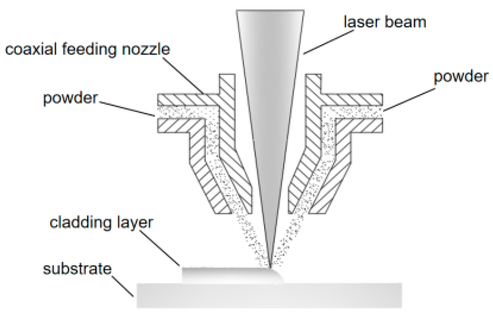
2. Experimental Materials and Methods

The substrate material used in the experiment was plate RT450 vermicular graphite cast iron. Before the experiment, the oxide layer on the surface of the substrate was removed with sandpaper, and then the oil stains on the surface were cleaned with acetone. The composition of non-standard nickel-based alloy powder and non-standard cobalt-based alloy powder selected for cladding is shown in Table 1. The particle size of the powder is in the range of 150 mesh to 300 mesh. Before the experiment, the powder was dried in a dryer. The drying parameters were: the drying temperature was 100–110 °C, and the drying time was 15 min. The equipment selected for the laser cladding experiment is the LDF 6000-100 fiber laser produced by the German Laserline company (Laserline, Koblenz, Germany). The laser cladding powder is a synchronous powder feeding method with a powder feeding rate of 18 g/min. Figure 1 is a schematic diagram of synchronous powder feeding. The nitrogen is used as the protective gas, and the flow rate is 18 L/min. In order to obtain a cladding layer with good surface condition and good quality forming, the parameters were optimized. The specific parameters were: the laser spot diameter is 3 mm, the laser power is 1300 W, the overlap rate is 65%, and the laser scanning speed is 10 mm/s. A layer of nickel-based transition layer with a length of 40 mm and a width of 40 mm was respectively clad on the substrate. On this basis, a cobalt-based cladding layer was clad on the surface. This sample was marked as sample 1. Two layers of cobalt-based materials with a length and a width of 40 mm were cladding on the substrate. This sample was marked as sample 2.
After the experiment, a wire cutting machine (ZhongXin, Taizhou, China) was used to cut a metallography sample with a size of 15 mm × 15 mm × 10 mm in the direction perpendicular to the laser scanning. The mixture of water and HF+HNO3 etched the nickel-based and cobalt-based samples. The scanning electron microscope Zeiss integrated with the energy spectrometer (ZEISS, Jena, Germany) was used to observe the structure of the coating and measure the elemental composition. The HVS-1000 Z hardness tester (LiDun, Shanghai, China) was used to perform a hardness test every 300 μm and every 200 μm in the horizontal and vertical directions of the sample. The hardness measurement load is 500 g, and the load duration is 15 s. The phase identification was characterized by an X-ray diffractometer (D/max-rA) (Rigaku, Tokyo, Japan), which worked under Cu K-α radiation (λ = 1.54 Å, 40 kV, 40 mA). The XRD pattern collection range was 10° ≤ 2θ ≤ 100°, and the scanning velocity was 4 °/min). The dimension of the test specimens was 15 mm × 15 mm × 10 mm. Cut a specimen with a size of 15 mm × 15 mm × 10 mm, polish the coating, prepare a 3.5% NaCl solution as the electrolyte, and select AgCl as the reference electrode. After immersing for 60 min, the electrochemical corrosion performance of the coating is characterized. The test piece with a size of 15 mm × 15 mm × 13 mm was cut, the coating was polished, and the friction and wear experiment was carried out using the MPX-3G type abrasion tester (HengXu, Jinan, China). SiN was selected as the friction pair, and the experiment was subjected to an external load of 120 N, and the experiment time was 30 min. According to “Determination of the Shear Strength of Metal Thermal Coatings” (GB/T13222), prepare the laser cladding shear samples, and configure them as GCr15 sleeves (quenched HRC60), and test the laser cladding layer and the bonding strength of compact graphite cast iron RUT-450.

3. Results Analysis and Discussion

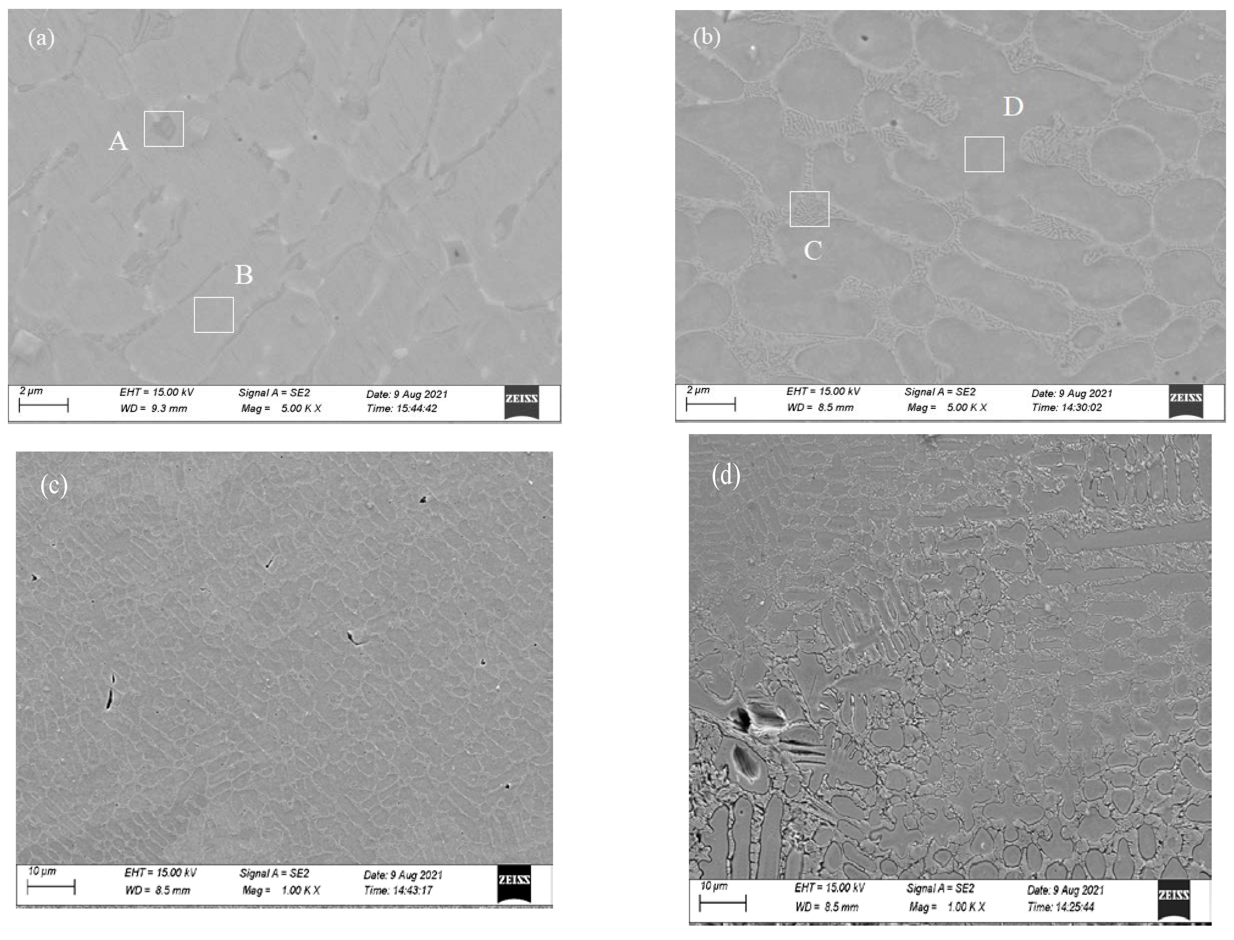
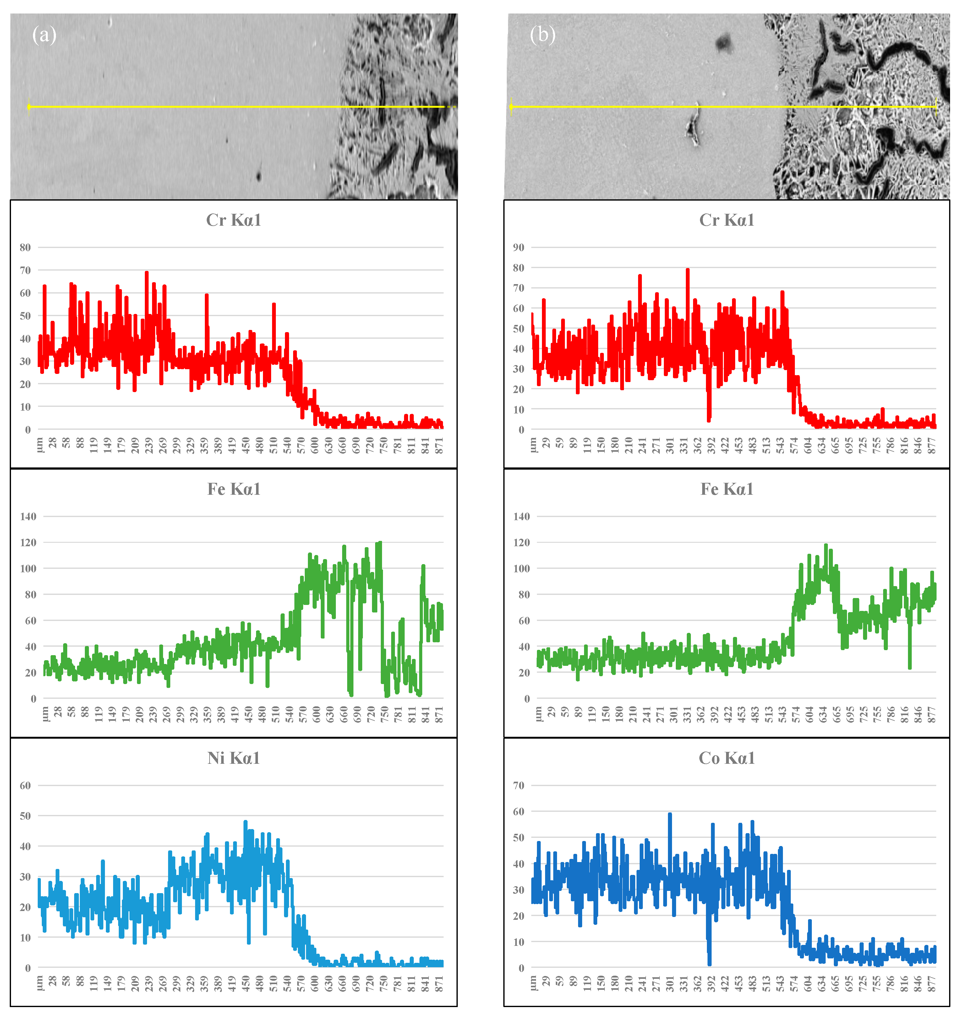
3.1. Microstructure and Phase Composition

Figure 2 shows the macro morphology of the cross section of the cladding layer. Figure 2 shows that the two cladding layer structures are dense and uniform, with a small amount of pores and no obvious cracks. The existence of a small amount of pores in the cladding layer is due to the rapid heating and cooling characteristics of the laser cladding process, which makes the amorphous powder insufficiently melted, and some space among the filled powders remained [17]. In addition, there is a clear macroscopic boundary between the cladding layer and the substrate, and the boundary line is a curve close to the horizontal on the left and right sides. A metallurgical bond is formed between the cladding layer and the substrate. The average thickness of the two different cladding layers is about 2 mm.
Figure 3a shows the surface structure of the Co-based cladding layer with a Ni-based transition layer, and Figure 3b shows the surface structure of the cladding layer without the transition layer. Figure 3a,b shows that the surface grains of the two cladding layers are fine. The surface layer of the structure with Ni-based as the transition layer is dispersed and distributed between the grains. However, there is a lamellar eutectic structure between the crystal grains without the Ni-based transition layer. This is because the laser has the characteristics of rapid heating and cooling. And the molten metal powder forms fine crystal grains under rapid solidification. Figure 3c shows the surface structure of the Co-based cladding layer at low magnification, and Figure 3d shows the bottom structure of the Co-based cladding layer at low magnification. Figure 3c,d shows the different grain growth direction of the Co-based cladding layer. The grain growth direction shows a clear difference between the surface and the bottom of the clad layer. This is because the grains grow along the approximate thermal gradient direction, and the thermal gradient and solidification rate are the most significant factors governing the grain growth [18]. Similarly, the Co-based cladding layer with a Ni-based transition layer has a similar grain growth direction. Table 2 shows the point energy spectrum data of the surface structure. Table 2 demonstrates that the surface structure of the Ni-based transition layer is enriched in Fe, Co, and Ni in the crystal nucleus, and C and Cr are enriched in the intergranular. The surface structure without the Ni-based transition layer is rich in Co and Fe in crystal nucleus, and C and Cr in the intercrystalline. According to the literature [19,20], the Cr, Mo, Fe, and C elements enriched in the dendrites mainly exist in the form of carbides. The surface structure with the transition layer is rich in Ni element between the nuclei. According to the intercrystalline enrichment of C and Cr elements, and combined with XRD analysis, the main carbides are Cr23C6 and Cr7C3. It shows that when the cobalt base is cladding on the transition layer, the transition layer is partially melted. And the melted transition layer area is fully fused with the cobalt base of the surface layer. There is a large amount of Fe element in the surface structure, which means that when the first layer is melted, the partially melted matrix enters the first layer. During the cladding of the second layer, the Fe element melted in the first layer enters the second layer. This situation is also observed in the energy spectrum scan of Figure 4.
In order to explore the dispersion of the alloying elements of the matrix vermicular graphite cast iron and the alloying elements of the cladding layer. The line scan analysis of the two cladding layers from the bottom of the cladding layer to the substrate was carried out. The results of the line scan analysis are shown in Figure 4. Figure 4 indicates that Fe alloying elements are distributed in both cladding layers. It can be seen that the matrix melts during the laser cladding process, and the alloy element Fe of the matrix diffuses into the cladding layer. During the laser cladding process, the alloy elements in the molten pool will flow due to the effect of heat. And the alloying elements Ni and Co in the lower part of the two cladding layers diffuse into the vermicular graphite cast iron matrix in a small amount. The distribution of alloying elements such as Cr and C is relatively uniform. As the distance from the substrate is closer, the content of alloying elements such as Ni and Co decreases sharply, and the content of Fe alloying elements increases sharply. The reason is that under the high temperature generated by laser cladding, micro-melting occurs between the substrate and the cladding layer, which leads to element diffusion and dilution. The above analysis shows that during the laser cladding process, the cladding layer elements (Ni and Co) and the matrix element (Fe) have been mixed. This indicates that a good metallurgical bond is formed between the cladding layer and the substrate.
Figure 5 shows the XRD patterns of the two cladding layers. Figure 5 shows that the two cladding layers are mainly composed of γ-Co, Cr23C6, Cr7C3, and Co0.72Fe0.28. Due to the rapid solidification of laser cladding, the γ-Co structure formed at high temperature is retained at room temperature. Both the nickel base and the cobalt base in the cladding powder contain a large amount of Cr element, which is a strong carbide forming element. The Cr element forms M7C3 and M23C6 carbides with the C element in the cladding material and the carbon diffused from the graphite in the matrix. And similar results have been achieved by Li [21,22,23]. In addition, in the nickel-based and cobalt-based composite cladding layer, the surface structure of the cladding layer forms a Ni-Cr-Fe intermediate phase. Figure 5 shows that the matrix element Fe diffuses into the nickel base of the transition layer during the cladding of the transition layer. During the cladding of the surface layer of the cobalt base, it further diffuses, thereby forming the Ni-Cr-Fe intermediate phase.

3.2. Hardness of the Cladding Layer

Figure 6a shows the hardness distribution from the surface of the cladding layer to the substrate. It can be observed from Figure 6a that the average hardness of the laser cladding Co-based cladding layer is 788 HV0.5. The average hardness of the Ni and Co-based composite cladding layer is 504 HV0.5. What is more, there is a hardness peak at the interface between the cladding layer and the substrate. The hardness of the laser cladding Co-based cladding layer is higher than that of the Ni and Co-based composite cladding layer. This is because the content of Cr and C in the laser cladding Co-based powder is higher than that in the Ni-based powder, and C and Cr elements have a strong affinity. After high temperature melting, the solidification process creates conditions for the formation of carbides. The formation of carbides (Cr23C6, Cr7C3) was also observed in XRD. In the Ni and Co-based composite cladding layer, the hardness of the cladding layer would be reduced due to the dilution effect of the Ni-based transition layer on the Co-based cladding layer, and the intermediate Cr-Ni-Fe generated. In the heat-affected zone, the hardness of the two cladding layers increased to 825 HV0.5 and 676 HV0.5, respectively. This is due to the formation of high-carbon martensite and ledeburite in the heat-affected zone.
Figure 6b shows the lateral hardness distribution on the surface of the cladding layer. Figure 6b shows that the lateral hardness has periodic fluctuations. The periodic hardness fluctuations are due to the use of multiple laser cladding for each cladding layer. The second irradiation of the laser causes the grains in the remelting zone to grow up by heating, and the structure to coarsen [24].

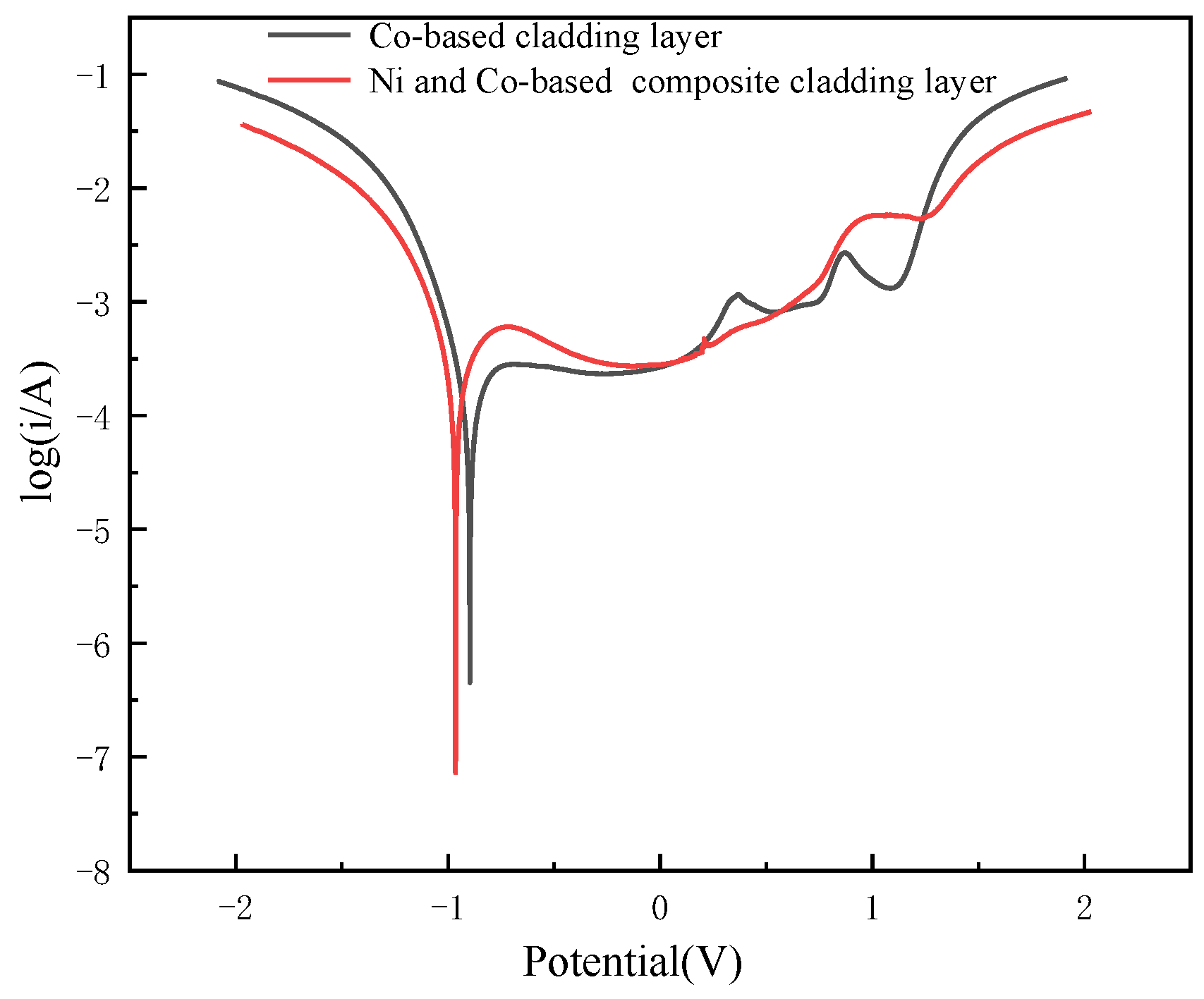
3.3. Corrosion Resistance of Cladding Layer

Figure 7 shows the Tafel polarization curves of the Ni and Co-based composite cladding layer and Co-based cladding layer in 3.5% NaCl solution. From Figure 7, it can be observed that the cladding layer undergoes positive polarization. The Tafel extrapolation method was used to obtain the self-corrosion potential and self-corrosion current of the cladding layer in 3.5% NaCl solution, and the results are shown in Table 3. The self-corrosion potential of the Co-based cladding layer is −0.896 V, and the self-corrosion current density is 2.469 × 10⁻⁴ A·cm−2. The self-corrosion potential of the Ni and Co-based composite cladding layer is −0.964 V, and the self-corrosion current density is 3.547 × 10⁻⁴ A·cm−2. The more positive the self-corrosion potential, the smaller the self-corrosion current density, the better the corrosion resistance of the clad surface. As a result, the Co-based cladding layer has better corrosion resistance. The reasons for the increased corrosion resistance of the cladding layer are as follows: (1) After laser cladding, the C and Fe elements in the vermicular graphite cast iron matrix enter the cladding layer to generate carbides and FeNi3 compounds, which form micro-batteries on the surface of the cladding layer and lead to local corrosion. Among them, carbides are used as cathodes, and γ-Co, etc., are used as anodes to reduce the corrosion of the surface of the cladding layer. The generation of a large number of compounds in the Ni and Co-based composite cladding layer will increase the self-corrosion current density and reduce the corrosion resistance. (2) During the laser cladding process, the metal elements such as Co, Cr, Ni, and Fe will produce bias separation during solidification, causing the inhomogeneous structure. Moreover, at the same time, different phases are generated between grains and grain boundaries, resulting in potential differences and the formation of micro-batteries. It can be seen from the microstructure SEM of Table 2 that the Ni and Co-based composite cladding layer has more C and Cr elements at the grain boundary, and the Co-based cladding layer contains more Co elements, so the Co-based cladding layer has better corrosion resistance. (3) In NaCl solution, Cl atoms are easily deposited in the defects such as holes and cracks on the surface of the cladding layer, which will destroy the oxide film formed on the surface of the cladding layer, and Cl atoms will further migrate to the defects, corrode the cladding layer and reduce the corrosion resistance of the cladding layer. Compared with defects such as cracks on the surface of the Ni and Co-based composite cladding layer, the surface of the Co-based cladding layer is better, the probability of local micro-battery is reduced, and the corrosion resistance is better [25]. (4) Elements such as Co, Ni, and Cr are passivated to produce a dense oxide film, generating a passivated phase and increasing the overall electrode potential of the cladding layer [26]. The corrosive medium of NaCl is effectively isolated from the surface of the cladding layer, acting as a corrosion barrier to prevent further corrosion of the surface of the cladding layer and improve the corrosion resistance of the cladding layer.

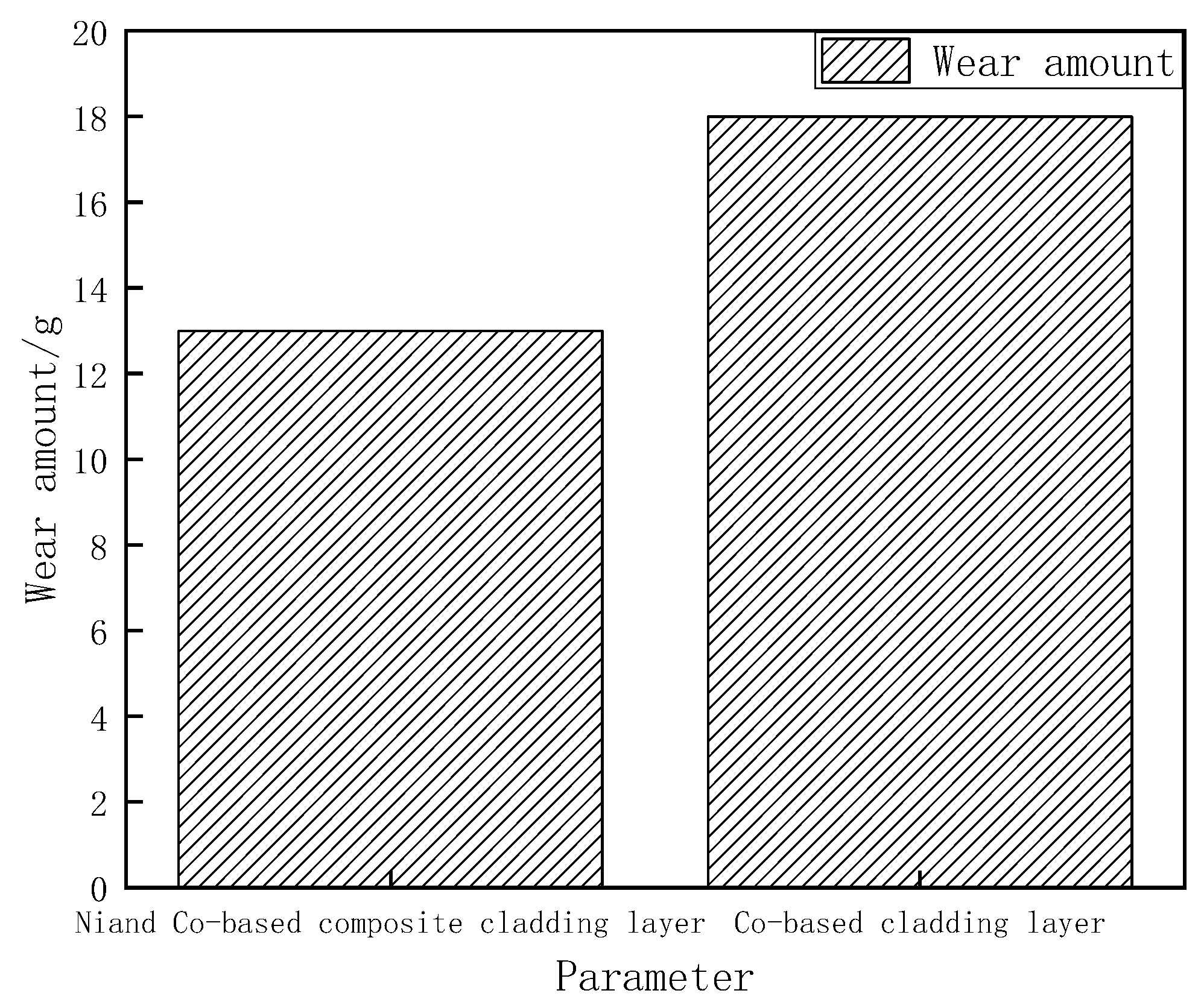
3.4. Wear Performance of Cladding Layer

Figure 8 shows the poor quality of the Ni and Co-based composite cladding layer, and the Co-based cladding layer before and after abrasion. It can be found that the Ni and Co-based composite cladding layer has lower wear and better wear resistance. Figure 9a shows the surface wear morphology of Ni and Co-based composite cladding layer after friction and wear experiments. It can be observed from Figure 9a that the Cr-Ni-Fe and other phases formed in the Ni and Co-based composite cladding layer reduce the hardness of the cladding layer. The hardness of the cladding layer is small and plastic deformation is prone to occur, and when it is sheared the contact area of the friction surface increases, and at this time, obviously cutting appears on the wear surface of the Ni and Co-based composite cladding layer. On the one hand, due to the generation of frictional heat, the coating is oxidized to different degrees. As shown in Table 4 EDS, there is still a high content of O elements on the wear surface. An oxide film will be formed on the friction surface, and the wear resistance will be improved accordingly. On the other hand, as the friction time progresses, wear is also progressing, the oxide film fatigues and falls off, forming oxide deposits, and finally serious oxidative wear occurs on the wear surface under the interaction between the wear surface and the wear part. Figure 9b shows the surface wear morphology of the Co-based cladding layer after the friction and wear experiment. It can be analyzed from Figure 9b that due to the combined effects of the formation of C and Cr carbides in the cobalt-based cladding layer, the hardness of the cobalt-based cladding layer is relatively high. Additionally, the friction is caused by the small particles falling off and the convex peaks on the high-hardness ball due to the continuous collision of the micro-protrusions on the surface of the friction pair and the three-body abrasive particles on the friction surface. During the reciprocating sliding process, the carbide in the cladding layer will fall off and cut the surface of the sample under the influence of the normal load, resulting in a large number of furrow wear marks. At the same time, fatigue wear occurs on the surface under the action of cyclic stress, and the growth of surface cracks causes large pieces of material to peel off and produce wear debris. In addition, a large amount of friction heat is easily generated during wear, and the temperature rises instantly. As shown in Table 4 EDS, the content of O elements in the wear zone is high, and oxide film is easily formed on wear, and the oxide film is easily destroyed by wear debris. At this time, the main wear mechanism is abrasive wear and slight oxidative wear. However, the wear amount of the Ni and Co-based composite cladding layer is relatively small. This is because the contact area of the worn surface is further increased, which will produce an obvious smooth layer [27], which changes the interaction of the worn surface. The work hardened layer [28] produced on the wear surface makes the wear surface have higher load-bearing capacity and wear resistance. As the frictional heat and the contact area of the friction surface increase, the probability that the friction surface combines with oxygen increases, and the oxide deposits increase. The force direction expands, forming a new smooth layer on the surface. It can be found from the analysis in Table 4 that the friction surface is mainly oxides of O, Co, and Cr, and the combined oxides of Cr and Co are easy to sinter to form an enamel layer at high temperatures [29], which can significantly reduce the amount of wear.

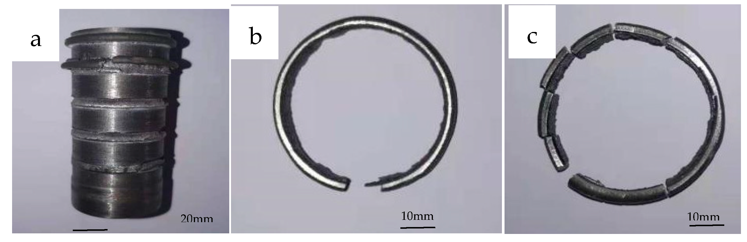
3.5. Mechanical Properties of Cladding Layer

Figure 10 shows the load-displacement curve of the indenter applied to the top of the sample when the cladding layer is separated from the cast iron matrix after the shear test is measured, and the shear bond strength is measured by the shear measurement method. As shown in Figure 11, the shear bonding strength of the laser cladding nickel-based cladding layer is about 480 MPa, and the shear bonding strength of the laser cladding nickel-based and cobalt-based composite cladding layer is about 387.5 MPa. It can be seen from the macro-photograph of the shear specimen in Figure 12 that the cladding layer has a higher bonding strength, and the fracture position of the cladding layer is on the base material. There is a difference in the shear strength of the fracture in the position of the base metal, which is because the thermal cycle of the laser cladding process affects the strength of the base metal. What is more, the integrity of the ring after the shear failure of sample 1 is obviously better than that of sample 2. Through analysis, it can be found that the surface of the cladding layer prepared by laser cladding on vermicular graphite cast iron RT450 has no defects such as pores and cracks, and the bonding strength of the laser cladding layer is higher than that of the base material.

4. Conclusions

(1)
The self-corrosion potentials of the Co-based cladding layer and the Ni and Co-based composite cladding layers are −0.896V and −0.964V, respectively, and the self-corrosion current density is 2.469 × 10⁻⁴ A·cm−2 and 3.547 × 10⁻⁴ A·cm−2. Due to the inhomogeneity of the material and the structure and the potential difference between the elements, the micro-batteries are formed. Compared with the Ni and Co-based composite cladding layer, the surface of the Co-based cladding layer has better corrosion resistance.
(2)
The wear of Ni and Co-based composite cladding layer is 0.72 times higher than that of Co-based cladding layers due to the combination of different compounds generated by the different elemental contents and the different degrees of plastic deformation, fatigue wear, and oxidative wear occurring on the surface of the cladding layers.
(3)
The average hardness value of the cladding region of the Co-based cladding layer is 788 HV0.5, and the average hardness value of the cladding region of the Ni and Co-based composite cladding layer is 504 HV0.5.
(4)
Due to the excellent mechanical properties of the Co-based cladding layer prepared by laser, the shear strength of the cladding layer is greater than that of the base material.

Author Contributions

Conceptualization, F.S. and M.P.; methodology, F.S.; validation, M.P., X.L. and K.C.; investigation, M.P., X.L. and K.C.; formal analysis, M.P.; writing—original draft preparation, M.P.; writing—review and editing, X.L. and K.C. All authors have read and agreed to the published version of the manuscript.

Funding

This research was funded by China Science and Technology Exchange Center grant number 2020YFE0200900.

Institutional Review Board Statement

Not applicable.

Informed Consent Statement

Not applicable.

Data Availability Statement

Not applicable.

Conflicts of Interest

The authors declare no conflict of interest.

References

  1. Hosdez, J.; Limodin, N.; Najjar, D.; Witz, J.-F.; Charkaluk, E.; Osmond, P.; Forré, A.; Szmytka, F. Fatigue crack growth in compacted and spheroidal graphite cast irons. Int. J. Fatigue 2020, 131, 105319. [Google Scholar] [CrossRef]
  2. Szmytka, F.; Michaud, P.; Rémy, L.; Köster, A. Thermo-mechanical fatigue resistance characterization and materials ranking from heat-flux-controlled tests. Application to cast-irons for automotive exhaust part. Int. J. Fatigue 2013, 55, 136–146. [Google Scholar] [CrossRef]
  3. Shaha, S.; Haque, M.M.; Khan, A.A. Wear Characteristics of Fe-C-Si and Fe-C-Al Cast Irons. Adv. Mater. Res. 2011, 264–265, 1928–1932. [Google Scholar] [CrossRef]
  4. Maleque, M.; Sugrib, S. The tribological behaviour of Fe-C-Al cast iron—Effect of temperature. Ind. Lubr. Tribol. 2013, 65, 320–327. [Google Scholar] [CrossRef]
  5. De Lacalle, L.N.L.; Valdivielso, A.F.; Amigo, F.J.; Sastoque, L. Milling with ceramic inserts of austempered ductile iron (ADI): Process conditions and performance. Int. J. Adv. Manuf. Technol. 2020, 110, 899–907. [Google Scholar] [CrossRef]
  6. Rodriguez, A.; De Lacalle, L.N.L.; Pereira, O.; Fernandez, A.; Ayesta, I. Isotropic finishing of austempered iron casting cylindrical parts by roller burnishing. Int. J. Adv. Manuf. Technol. 2020, 110, 753–761. [Google Scholar] [CrossRef]
  7. Sun, F.-Z.; Li, Y.; Tan, W.-D.; Pang, M. Effect of laser scanning speed on the thermal-mechanical coupling field of laser remelting of valve seat. Optik 2021, 225, 165776. [Google Scholar] [CrossRef]
  8. Siddiqui, A.A.; Dubey, A.K. Recent trends in laser cladding and surface alloying. Opt. Laser Technol. 2021, 134, 106619. [Google Scholar] [CrossRef]
  9. Benyounis, K.; Fakron, O.; Abboud, J.; Olabi, A.G.; Hashmi, M. Surface melting of nodular cast iron by Nd-YAG laser and TIG. J. Mater. Process. Technol. 2005, 170, 127–132. [Google Scholar] [CrossRef]
  10. Gendron, M.; Hazel, B.; Boudreault, E.; Champliaud, H.; Pham, X.-T. Coupled thermo-electromagnetic model of a new robotic high-frequency local induction heat treatment system for large steel components. Appl. Therm. Eng. 2019, 150, 372–385. [Google Scholar] [CrossRef]
  11. Li, Y.; Dong, S.; Yan, S.; Liu, X.; He, P.; Xu, B. Surface remanufacturing of ductile cast iron by laser cladding Ni-Cu alloy coatings. Surf. Coat. Technol. 2018, 347, 20–28. [Google Scholar] [CrossRef]
  12. Liu, J.; Liu, H.; Tian, X.; Yang, H.; Hao, J. Microstructural evolution and corrosion properties of Ni-based alloy coatings fabricated by multi-layer laser cladding on cast iron. J. Alloys Compd. 2020, 822, 153708. [Google Scholar] [CrossRef]
  13. Ding, Y.; Liu, R.; Yao, J.; Zhang, Q.; Wang, L. Stellite alloy mixture hardfacing via laser cladding for control valve seat sealing surfaces. Surf. Coat. Technol. 2017, 329, 97–108. [Google Scholar] [CrossRef]
  14. Selvi, S.; Sankaran, S.; Srivatsavan, R. Comparative study of hardfacing of valve seat ring using MMAW process. J. Mater. Process. Technol. 2008, 207, 356–362. [Google Scholar] [CrossRef]
  15. Paczkowska, M.; Makuch-Dziarska, N.; Kulka, M. The influence of various cooling rates during laser alloying on nodular iron surface layer. Opt. Laser Technol. 2018, 102, 60–67. [Google Scholar] [CrossRef]
  16. Bourahima, F.; Helbert, A.-L.; Ji, V.; Rege, M.; Courteaux, A.; Brisset, F.; Baudin, T. Optimization of Microstructural Evolution during Laser Cladding of Ni Based Powder on GCI Glass Molds. Key Eng. Mater. 2019, 813, 185–190. [Google Scholar] [CrossRef]
  17. Liu, X.; Bi, J.; Meng, Z.; Li, R.; Li, Y.; Zhang, T. Tribological behaviors of high-hardness Co-based amorphous coatings fabricated by laser cladding. Tribol. Int. 2021, 162, 107142. [Google Scholar] [CrossRef]
  18. Pérez-Ruiz, J.D.; de Lacalle, L.N.L.; Urbikain, G.; Pereira, O.; Martínez, S.; Bris, J. On the relationship between cutting forces and anisotropy features in the milling of LPBF Inconel 718 for near net shape parts. Int. J. Mach. Tools Manuf. 2021, 170, 103801. [Google Scholar] [CrossRef]
  19. Liu, P.; Wang, Z.; Xiao, Y.; Horstemeyer, M.F.; Cui, X.; Chen, L. Insight into the mechanisms of columnar to equiaxed grain transition during metallic additive manufacturing. Addit. Manuf. 2019, 26, 22–29. [Google Scholar] [CrossRef]
  20. Xue, K.; Lu, H.; Luo, K.; Cui, C.; Yao, J.; Xing, F.; Lu, J. Effects of Ni25 transitional layer on microstructural evolution and wear property of laser clad composite coating on H13 tool steel. Surf. Coat. Technol. 2020, 402, 126488. [Google Scholar] [CrossRef]
  21. Li, Y.; Dong, S.; Yan, S.; Liu, X.; He, P.; Xu, B. Microstructure evolution during laser cladding Fe-Cr alloy coatings on ductile cast iron. Opt. Laser Technol. 2018, 108, 255–264. [Google Scholar] [CrossRef]
  22. Jeshvaghani, R.A.; Harati, E.; Shamanian, M. Effects of surface alloying on microstructure and wear behavior of ductile iron surface-modified with a nickel-based alloy using shielded metal arc welding. Mater. Des. 2011, 32, 1531–1536. [Google Scholar] [CrossRef]
  23. Cui, G.; Han, B.; Zhao, J.; Li, M. Comparative study on tribological properties of the sulfurizing layers on Fe, Ni and Co based laser cladding coatings. Tribol. Int. 2019, 134, 36–49. [Google Scholar] [CrossRef]
  24. Wang, Z.Y.; Lin, J.; Lei, Y.P. Microstructure and properties of Stellite6 coating prepared by laser cladding. J. Laser Infrared 2020, 50, 1172–1177. [Google Scholar]
  25. Guo, J.Z. Investigation on Microstrue and Properties of Coating Prepared with Diverse Ni-Al materials. Ph.D. Thesis, Xi’an University of Technology, Xi’an, China, 2010. [Google Scholar]
  26. Zhang, K.Y.; Han, H.S.; Yang, C. Microstructures and Properties of Hastelloy C276 on Cast Iron Surface by Laser Cladding. J. Surf. Technol. 2021, 50, 109–115. [Google Scholar]
  27. Wu, X.W.; Zeng, X.Y.; Zhu, B.D. Melting and burning law of nickel-based WC cermet laser cladding coatings. J. Acta Metall Sin. 1997, 1282–1288. [Google Scholar]
  28. Zhang, J.; Zhang, X.; Liu, Q.; Yang, S.; Wang, Z. Effects of Load on Dry Sliding Wear Behavior of Mg–Gd–Zn–Zr Alloys. J. Mater. Sci. Technol. 2017, 33, 645–651. [Google Scholar] [CrossRef]
  29. Zhang, C.J.; You, X.Q.; Song, X.F. The effect of laser remelting on the surface microstructure of electric steel-bonded cemented carbide. J. Cem. Carbide 2006, 04, 198–202. [Google Scholar]
Figure 1. Schematic diagram of synchronous powder feeding.
Coatings 11 01241 g001
Figure 2. Macro morphology of the cross section of the cladding layer.
Coatings 11 01241 g002
Figure 3. Microstructure of the two cladding layers. (a) High magnification electron microscope image of the surface layer of Ni and Co-based composite cladding. (b) High magnification electron micrograph of the surface of the Co-based cladding. (c) Low magnification electron micrograph of the surface of the Co-based cladding layer. (d) Low magnification electron micrograph of the bottom layer of the Co-based cladding layer.
Coatings 11 01241 g003
Figure 4. Line scan results of two cladding layers. (a) Schematic diagram of the line scan of the lower part of the Ni and Co-based composite cladding layer. (b) Schematic diagram of the line scan of the bottom of the Co-based cladding layer.
Coatings 11 01241 g004
Figure 5. XRD patterns of two cladding layers.
Coatings 11 01241 g005
Figure 6. The microhardness of the two cladding layers. (a) The hardness from the surface of the cladding layer to the substrate. (b) The lateral microhardness of the cladding layer.
Coatings 11 01241 g006
Figure 7. Tafel polarization curves of different protective coatings in 3.5% NaCl solution.
Coatings 11 01241 g007
Figure 8. Surface wear of nickel-based and cobalt-based composite cladding layers and cobalt-based cladding layers.
Coatings 11 01241 g008
Figure 9. Wear morphology of cladding layer. (a) Morphology of nickel-based and cobalt-based composite cladding layer. (b) Morphology of cobalt-based cladding layer.
Coatings 11 01241 g009
Figure 10. Load-displacement curve of cladding layer.
Coatings 11 01241 g010
Figure 11. Shear strength of cladding layer.
Coatings 11 01241 g011
Figure 12. Macro photo of shear specimen after fracture. (a) Sample matrix. (b) Sample 1 (nickel-based and cobalt-based composite cladding layer). (c) Sample 2 (cobalt-based cladding layer).
Coatings 11 01241 g012
Table 1. Vermicular graphite cast iron RT450 and powder chemical composition (wt.%).
Materials/ElementsCSiMnCuFeNiCoNbCrAlW
RT4503.702.600.500.6Bal//////
Non-standard nickel-based powder0.050.040/0.0518.60Bal0.085.120.500.5/
Non-standard cobalt-based powder1.201.300.25/2.502.20Bal/29.30/5.00
Table 2. Point energy spectrum analysis results of the cladding layer in different areas (wt.%).
Test AreaCCrFeCoNiW
A32.7440.317.0810.364.881.06
B--26.0718.2430.5121.240.76
C22.9634.1210.4928.55--1.66
D11.6120.5415.5447.182.000.92
Table 3. Electrochemical corrosion performance Self-corrosion voltage and self-corrosion current density.
SampleEcorr/VIcorr/A·cm−2
Co-based cladding layer−0.896832.4688 × 10−4
Ni and Co-based composite cladding layer−0.963933.5465 × 10−4
Table 4. Wear surface energy spectrum (atomic fraction) of nickel-based cladding layer and cobalt-based cladding layer.
Location/ElementCrCoFeCONi
Ni and Co-based composite cladding layer8.7111.005.9340.8523.057.35
Co-based cladding layer17.6128.817.0219.8722.51/
Publisher’s Note: MDPI stays neutral with regard to jurisdictional claims in published maps and institutional affiliations.

