Article

Numerical Simulation of the Effect of Freeze–Thaw Cycles on the Durability of Concrete in a Salt Frost Environment

1
Water Conservancy and Civil Engineering College, Inner Mongolia Agricultural University, Huhhot 010018, China
2
School of Economics and Management, Inner Mongolia Technical College of Construction, Huhhot 010070, China
*
Author to whom correspondence should be addressed.
Coatings 2021, 11(10), 1198; https://doi.org/10.3390/coatings11101198
Submission received: 1 September 2021 / Revised: 18 September 2021 / Accepted: 21 September 2021 / Published: 30 September 2021
(This article belongs to the Special Issue Corrosion and Degradation of Materials)

Abstract

:
In order to improve the accuracy of the analysis of the impact of freeze–thaw cycle on concrete durability in a salt freezing environment, the numerical simulation of the impact of the freeze–thaw cycle on concrete durability in a salt freezing erosion environment is studied in this paper. Firstly, considering the influence of axial force and bending moment on the relationship between bending moment and curvature, a concrete fiber beam column model is established. Then, according to the joint influence of temperature field, stress field and seepage field on concrete in the process of freezing and thawing, the control differential equation of the freezing and thawing cycle is established. The freeze–thaw damage section is divided, the non-uniform distribution of freeze–thaw damage is determined, and the division of the freeze–thaw damage section is completed. According to the linear relationship between freeze–thaw damage degree, relative dynamic elastic modulus, freeze–thaw cycle times and position variables, the durability of concrete is numerically simulated, and the attenuation law of bond strength at different section depths after freeze–thaw is determined. The results show that the temperature curve simulated by the design method is consistent with the actually measured temperature curve, which can better reduce the temperature change of the inner core of the test block during freezing and thawing, and the relative dynamic elastic modulus is in good agreement with the actual value, which can prove that the method in this paper has certain practical application value. It is expected to provide some reference for solving the durability problem of concrete in a salt frost erosion environment and the optimal design of concrete structures.

1. Introduction

Various causes have led concrete structures to suffer from destruction, collapse and other material durability problems in the past 40 or 50 years, seriously affecting the normal benefits and safe use of these structures [1]. Many engineering structures have to end their service ahead of time, and countries all over the world have paid a huge price for this. In practical engineering, the durability failure of or damage to concrete structures are common, causing huge economic losses [2]. Over a long period, under the combined action of salt erosion and freeze–thaw and other environmental factors, the damage to concrete structures in irrigation areas is very serious, and a considerable number of concrete structures lose their functions prematurely before reaching the designed lifetime, which has a big impact on the safety and benefits of water projects. A salt frost environment is an environment where crystals such as frost precipitate on the concrete surface, making it more prone to freeze–thaw. The mechanism of freezing and thawing is that the water in the pores of the soil and its matrix metal or rock expands in the freezing process, resulting in the continuous increase in cracks and the overall fragmentation of soil or rock. After ablation, its anti-corrosion stability is greatly reduced. Under the action of gravity, the rock and soil begin to move downward along the slope. In cold and dry areas with lakeside sedimentary rocks as the main foundation conditions, the sulfate and chloride ions abundant in groundwater and soil become the main media of erosion damage to concrete buildings. When the concrete structure is in a working environment with freeze–thaw in winter, it will suffer from the combined action and linkage damage of two or more elements. Concrete buildings suffer from the combined action of salt erosion and freeze–thaw over a long period. The damage and performance deterioration of concrete structures in these areas are serious, and a considerable number of concrete structures are damaged prematurely before reaching the designed lifetime. At present, in order to alleviate freeze–thaw damage, scholars have proposed various mitigation methods, such as adding creto material, changing the mix proportion parameters and the connection type of foundation parts, and using freeze–thaw- and corrosion-resistant materials [3,4,5,6,7].
Although these mitigation methods have been proposed, in order to improve the pertinence of mitigation methods, it is necessary to analyze the impact of the melting cycle on concrete durability. Therefore, some scholars have studied this. For example, Wang et al. examined a durability analysis method of shotcrete lining under the coupling action of nitric acid erosion and the freeze–thaw cycle. Taking a long highway tunnel with a shotcrete single-layer permanent lining in a cold area as the engineering background, the pore structure of concrete under the combined action of nitric acid erosion and the freeze–thaw cycle was characterized and analyzed by means of the straight-line conductor method [8]. Peng et al. predicted and analyzed the corrosion life of reinforced concrete structures in a salt freeze–thaw environment. Based on Fick’s second law, a chloride ion transport model considering time, temperature, humidity, chloride ion binding and freeze–thaw damage effects in concrete was established to study the durability and life of concrete [9]. Tian, Y. G also studied the durability of highway C50 high performance concrete, combined with the rich local industrial wastes (fly ash and mineral powder), and prepared C50 concrete with excellent performance, so as to study the influence of mineral admixtures on the durability of concrete [10]. Yang et al. conducted experimental research on the freeze–thaw damage depth of concrete in a deicing salt environment. By comparing the change law of concrete’s appearance, the detection results of ultrasonic equipment and the penetration of concrete contact surface, the damage depth of concrete under different freeze–thaw cycles were obtained. It was concluded that after 20 freeze–thaw cycles, the freeze–thaw damage of concrete begins to expand into the interior of concrete. In order to alleviate the impact of freeze–thaw, relevant measures can be put forward according to the above research results [11]; in order to alleviate the impact of freeze–thaw, Huang, J. B and others also analyzed the freeze–thaw deterioration and damage characteristics of existing cracked concrete, used the prefabricated crack method to simulate the concrete with cracks in actual projects, studied the damage deterioration process and mechanical characteristics of cracked concrete under the conditions of the freeze–thaw cycle, and obtained the calculation formula of the peak stress of the prefabricated crack specimen and the number of freeze–thaw cycles. Relevant personnel can take necessary mitigation measures to solve relevant freeze–thaw problems according to the calculated formula [12]. Although the above scholars have studied this, there is a problem of a poor numerical analysis effect. In order to solve the above problems and improve the accuracy of the impact analysis of the freeze–thaw cycle on concrete durability in a salt freezing environment, this paper puts forward a new research method, namely the following innovative research:
(1)
In the analysis process, considering the influence of the axial force and bending moment on the relationship between bending moment and curvature, a concrete fiber beam column model is established to divide the section of concrete members into several discrete small elements and improve the characteristics of different small elements of concrete;
(2)
According to the joint influence of temperature field, stress field and seepage field on concrete in the process of freeze–thaw, the control differential equation of freeze–thaw cycle is established and substituted into the concrete fibers at different positions of the section, so as to analyze the fiber section in the process of freeze–thaw damage evolution;
(3)
Based on the coupling algorithm, the freeze–thaw damage section is divided, the non-uniform distribution of freeze–thaw damage is determined, and the division of freeze–thaw damage section is completed;
(4)
According to the linear relationship between the freeze–thaw damage degree, the relative dynamic elastic modulus, number of freeze–thaw cycles and location variables, the durability of concrete is numerically simulated. On this basis, the attenuation law of bond strength at different section depths after freeze–thaw is determined.
Through the above four innovations, this paper completes the numerical simulation of the effect of freeze–thaw cycle on concrete durability in a salt frost environment.

2. Numerical Simulation of the Effect of Freeze–Thaw Cycles on the Durability of Concrete in Salt Frost Environment

2.1. Establishment of Concrete Fiber Beam Column Model

The fiber model divides the cross section of the concrete member into a certain number of discrete small elements, and the mechanical properties of each small element are expressed by the axial stress–strain relationship of the steel bar and concrete. Furthermore, the lateral displacement of the column can be obtained along the longitudinal direction of the member, which has high accuracy. The fiber model is established in OPENSEES Windows version 3.2.2 (as shown in Figure 1), and the element type is based on a nonlinear beam column element.
In the displacement-based model, the element displacement field is expressed as the function of the node displacement field, which is the approximation of the real structural element displacement field. In order to obtain a good approximation result, it is necessary to divide a member into several elements. In order to determine the number of fibers needed for cross-section analysis, sensitivity analysis is carried out, and 50 × 50 fibers are obtained, which can basically achieve the balance. The concrete model of OPENSEES is selected as Concrete0l. The model is based on the uniaxial constitutive relation of concrete, and does not consider the tensile strength of concrete. The relationship is determined by the Karsan-Jirsa unloading rule [13]. The parameters include the axial compressive strength and corresponding strain, the residual strength and corresponding strain. The formula for calculating the axial strength and peak strain of unfrozen concrete is as follows:
{ w = 0.76 p u = w 2500 w
In Formula (1), w is the axial strength of concrete; p is the residual strength of concrete; u is the peak strain; and w is the peak intensity. The constitutive model of concrete in the core area is expressed in sections. The first part selects the Concrete04 model in OPENSEES. The parameters needed to be defined in the model are: the axial compressive strength and corresponding strain of concrete, the elastic modulus of concrete and the ultimate compressive strain of concrete. For restrained concrete, the value of the elastic modulus is the same as that of unconstrained concrete. Considering the influence of stirrups on the strength and ductility of concrete in the core area, the compressive strength and peak strain of unconstrained concrete are modified to obtain the corresponding value of constrained concrete. The second part is the Minmax material in OPENSEES, which can be used to obtain the strain threshold. In this paper, the third part is set as the Mander constitutive model failing when the concrete strain exceeds the ultimate compressive strain, and the stress–strain relationship enters the linear degradation [14]. The Steel02 model in OPENSEES is selected as the constitutive model of reinforcement, which can consider the isotropic strain hardening phenomenon and Bauschinger effect of reinforcement, and the calculation efficiency of the model is high, which is in good agreement with the results of the repeated loading test of reinforcement. The parameters to be defined in the Steel02 model mainly include: the yield strength, initial elastic modulus, strain hardening rate, the control parameter of curve curvature from the elastic transition to the plastic phase, the isotropic hardening parameter and initial stress value. Because the freeze–thaw cycle mainly affects the mechanical properties of concrete, the same selection method is adopted for the constitutive model of steel bars of freeze–thaw and non-freeze–thaw specimens.

2.2. Governing Differential Equations of Freeze Thaw Cycles

In this section, the relative dynamic elastic modulus of concrete is used as the physical damage index to measure the degree of freeze–thaw damage. The relative dynamic elastic modulus refers to the ratio of stress and strain of an object under dynamic load. It is generally measured by a dynamic resistance strain gauge and an acoustic instrument. Based on the material property test data in the existing research, the uneven distribution and development law of damage are established, and then the damage evolution law of concrete mechanical properties with the change is formed. Thus, under the condition of given cycles, different constitutive parameters can be given to the fibers at different positions of the member section, and the non-uniformity of freeze–thaw damage can be considered. The freeze–thaw process of concrete is affected by the joint action of the temperature field, stress field and seepage field. Firstly, it is controlled by the temperature field. The freezing and thawing cycle means that the temperature decreases and increases continuously. The second is the effect of the stress field, which is due to the pore pressure caused by the freezing of water in the pores. Finally, it is also affected by the seepage field, which is due to the influence of water migration and phase transformation in pores. In order to describe the influence of the three fields, there are respective governing equations. In the process of freeze–thaw cycle, the water in the pores of porous materials will produce the transformation of the liquid phase and the gas phase. The heat conduction equation of water phase’s latent heat is as follows [15]:
m c T t = ( α T ) + λ p t
In Formula (2), m is the density of the system; c is the specific heat capacity of the system; T is temperature; t represents time; p is the thermal conductivity of the system; and α is the thermal conductivity of the system. In the porous system, the relationship between effective stress and strain is as follows [16]:
χ = B γ ( 1 φ 1 φ 2 ) η E
In Formula (3), χ is the stress; B is the stiffness matrix; γ is the total strain; φ 1 and φ 2 are the elastic modulus of the system and aggregate; η is the average pore pressure; and E is the identity matrix. In the absence of external load, there is an equilibrium differential equation of mechanical field. The migration obeys Darcy’s law, and the water in the pores also conforms to the law of mass conservation in the process of liquid and solid phase changes. According to the constitutive equation of each phase, the Darcy seepage field equation in a porous media system can be deduced as follows [17]:
S = ( θ ν S ) + V β δ
In Formula (4), S represents the permeation field of the system; θ is the permeability coefficient; ν is the dynamic viscosity coefficient of water; V is the expansion volume of the system; β is porosity; and δ is volume strain. In the process of failure, the temperature, stress and seepage field are coupled with each other, jointly promoting the damage. Therefore, the failure process of concrete in the freeze–thaw cycle can be described by the above-mentioned differential equations. When the number of freeze–thaw cycles does not reach a certain value, the change in the relative dynamic elastic modulus is small. Therefore, the critical value of freeze–thaw cycles is proposed to characterize this trend, and the critical value increases linearly with section depth. When the critical number is exceeded, the relative dynamic elastic modulus decreases linearly with the increase in the number of cycles, and the degradation rate is similar at different section depths. Therefore, a consistent degradation rate of the relative dynamic elastic modulus at different positions of the cross section is proposed to characterize this trend. On this basis, the relative dynamic elastic modulus of concrete is used as the bridge between the constitutive parameter eigenvalue of concrete before and after freeze–thaw and the section depth and freeze–thaw cycles. For the fiber section, the above-mentioned modified freeze–thaw concrete constitutive equation can be substituted into the concrete fibers at different positions of the section, so as to form the fiber section which can consider the evolution process of freeze–thaw damage.

2.3. Division of Freeze–Thaw Damage Section Based on Coupling Algorithm

During the freeze–thaw cycle, the freeze–thaw damage on the cross section of the specimen is not evenly distributed, but gradually decreases with the increase in the distance from the freeze–thaw surface. If the non-uniform distribution of freeze–thaw damage is ignored and the degree of freeze–thaw damage is assumed to be consistent in the whole section of the specimen, there will be large errors in the calculation of bearing capacity and deformation of the specimen in the process of simulation analysis. Therefore, it is very important to the damage distribution of the specimen that we ensure the accuracy of the analysis results. In this paper, the freeze–thaw damage section is divided based on the coupling algorithm. In this coupling algorithm, the whole computational domain is discretized into LBM grids by means of the partition alternating solution. Among them, the grid occupied by structure is marked as domain, and the rest of the grid is marked as watershed. The fluid movement is solved by the fluid solver, and the displacement of the structure is solved by the structure solver. At each time step, the algorithm solves the flow field and the structure domain in turn, and exchanges the force and displacement information of the fluid structure coupling surface. After obtaining the structure displacement, it is input into the fluid solver to determine the position of the fluid structure coupling surface to update the basin grid. In the whole solution time domain, the structure coupling problem can be solved alternately by performing the process. According to the variation of the relative dynamic elastic modulus at different distances from contact surface, the relationship between the critical influence depth and the number of cycles is proposed as follows:
h o = 11.7 ( M 2.5 ) 0.9
In Formula (5), h o is the critical depth of freeze–thaw—that is, the maximum depth of the cross-section of the specimen affected by the freeze–thaw cycle—and M is the number of freeze–thaw cycles corresponding to the freeze–thaw cycle test. Based on the damage equivalence principle, the relative dynamic elastic modulus is selected as the quantitative index of freeze–thaw damage. Using the linear interpolation method, 80 freeze–thaw cycles of NAC, RAC50 and RAC100 can be obtained under the non-standard freeze–thaw test, which are equivalent to 200 cycles of the standard freeze–thaw test, respectively. NAC, RAC50 and rac100 refer to different types of concrete. NAC is small particle size asphalt concrete and RAC50 and RAC100 refer to recycled concrete with a 50% and 100% replacement rate of coarse aggregate. Based on this, combined with Formula (5), the critical influence depth of freeze–thaw of concrete specimen in this paper can be obtained:
h o = 0.15 n 1 M n 2 0.9
In Formula (6), n 1 and n 2 represent the number of freeze–thaw cycles under the standard and non-standard freeze–thaw tests, and M represents the number of freeze–thaw cycles corresponding to the non-standard freeze–thaw test in this paper. After determining the depth of the freeze–thaw effect, it is necessary to further estimate the freeze–thaw damage distribution on the section. After the freeze–thaw cycle, the relative dynamic elastic modulus of the specimen section basically obeys the linear distribution. In order to simplify the analysis, it is assumed that the freeze–thaw damage degree of the section decreases linearly from the outside to the inside, the outermost edge of the section is the relative dynamic elastic modulus of the prism in the freeze–thaw test, and the innermost edge of the freeze–thaw influence depth in the section is 1 (the freeze–thaw damage degree is zero). Therefore, the constitutive relationship of a recycled concrete pier at different positions of the section can be determined according to the values of the relative dynamic elastic modulus and replacement rate of recycled coarse aggregate, and then the section division of the specimen can be completed. In this paper, the concrete layer is divided into 15 mm grids.

2.4. Numerical Simulation of Concrete Durability

According to the linear relationship between the relative dynamic elastic modulus of damage degree and location variables, the durability is numerically simulated to determine the degradation law of bond strength at different section depths after freeze–thaw. The critical number of freeze–thaw cycles is used to represent the number of freeze–thaw cycles required for concrete to begin to experience freeze–thaw damage at a certain section depth. On this basis, the degradation law of bond strength at different section depths after freeze–thaw can be established only by establishing the change in relative bond strength with the freeze–thaw damage index. The relative bond strength and the corresponding freeze–thaw damage degree data obtained from the pull-out test of freeze–thaw specimens are analyzed, and these data have a linear regression. Considering the boundary conditions (damage index = 1, relative bond strength = 1 without freeze–thaw damage), the regression formula coefficient is obtained according to the least square method, and the damage model of the freeze–thaw damage index with respect to cycle number and location variable is obtained. The concrete expression is as follows:
I = { 1 , K 1.05 h 0.23 1 0.0112 [ h ( 1.05 h 0.23 ) ] , K > 1.05 h 0.23
In Formula (7), I is the freeze–thaw damage index; K is the number of cycles; h is the position variable of section depth. The relationship between bond strength and position variables can be expressed as follows:
Y = { 1 , K 1.05 h 0.23 1.05 0.0104 [ h ( 1.05 h 0.23 ) ] , K > 1.05 h 0.23
In Formula (8), Y is the freeze–thaw bond strength. The relative dynamic elastic modulus of each mix proportion model decreases continuously. Additionally, with the increase in time, the amount of ice increases gradually, resulting in greater frost heaving pressure. The porosity inside the concrete increases, and micro-cracks are gradually generated, which eventually leads to the connection between the pores, and micro cracks gradually increase, causing greater damage to the concrete [18]. In this vicious circle, the freeze–thaw damage of concrete is more serious, which is reflected in the dynamic modulus, and the value of dynamic modulus decreases faster. According to the established bond strength model of freeze–thaw damage, within a certain range of anchorage length, the bond stress after freeze–thaw has a linear relationship with the position variable. In order to facilitate the subsequent derivation, firstly, the coordinate system is established according to the boundary conditions of the anchorage end of the steel bar; that is, the stress and strain of the steel bar are zero, and the required stress penetration length after freeze–thaw damage can be obtained. This length indicates that the bond stress degenerates only within this depth range [19]. In the elastic stage, the model still satisfies the force balance condition, and the bond stress is trapezoidal in the range of stress penetration length. Under the condition of given reinforcement stress, the unique solution regarding the length of seepage stress is obtained. At this time, the stress increment at both ends of the reinforcement in the micro section has the surrounding bond stress balance. When entering the area not affected by freezing and thawing, the average stress calculation method is used to obtain the corresponding slip. In the post yield stage, the position coordinates of the steel bar are obtained according to the equilibrium equation. The total slip can be divided into yield slip and new slip after the steel bar enters the plastic stage. In conclusion, regardless of whether the reinforcement yield exists or not, under the condition of given reinforcement stress, the slip value can be calculated by solving the stress penetration length, and so it can be directly applied to the analysis at the component level.

3. Experiment

3.1. Experimental Preparation

First, raw materials of NAC natural aggregate concrete, RAC50 recycled concrete and RAC100, mainly including cement, coarse aggregate, fine aggregate, water and the mixture, were prepared and combined into a uniform mixture as required to obtain high-strength concrete performance. Relevant standards for the mix proportion design of ordinary concrete (JGJ55–2011) were followed in the experiment [20].
In this paper, the numerical simulation of concrete under salt frost erosion environment was studied. In order to verify the effect of this method, the test results were compared with the temperature shock field test results. The temperature impact field experiment was carried out with reference to the actual environment of the concrete structure. Material parameters are shown in Table 1.
The grid type was a linear order three-dimensional stress type—that is, eight nodes in a linear hexahedral element c3d8r—which was calculated by means of the reduced integral and hourglass control method. Because there were many temperature points in the test block and the amount of temperature sampling and measurement was large, the key points of the structure were selected for temperature curve measurement. The center of the concrete corresponded to the temperature sensor. The key points of the selected structure in this experiment were located at 50 mm from the lower surface, 50 mm from the sample’s center and 50 mm from the upper surface, marked as A, B and C, respectively. Based on the above tests, the temperature impact field test was carried out, and the numerical simulation was carried out by using the method in this paper.

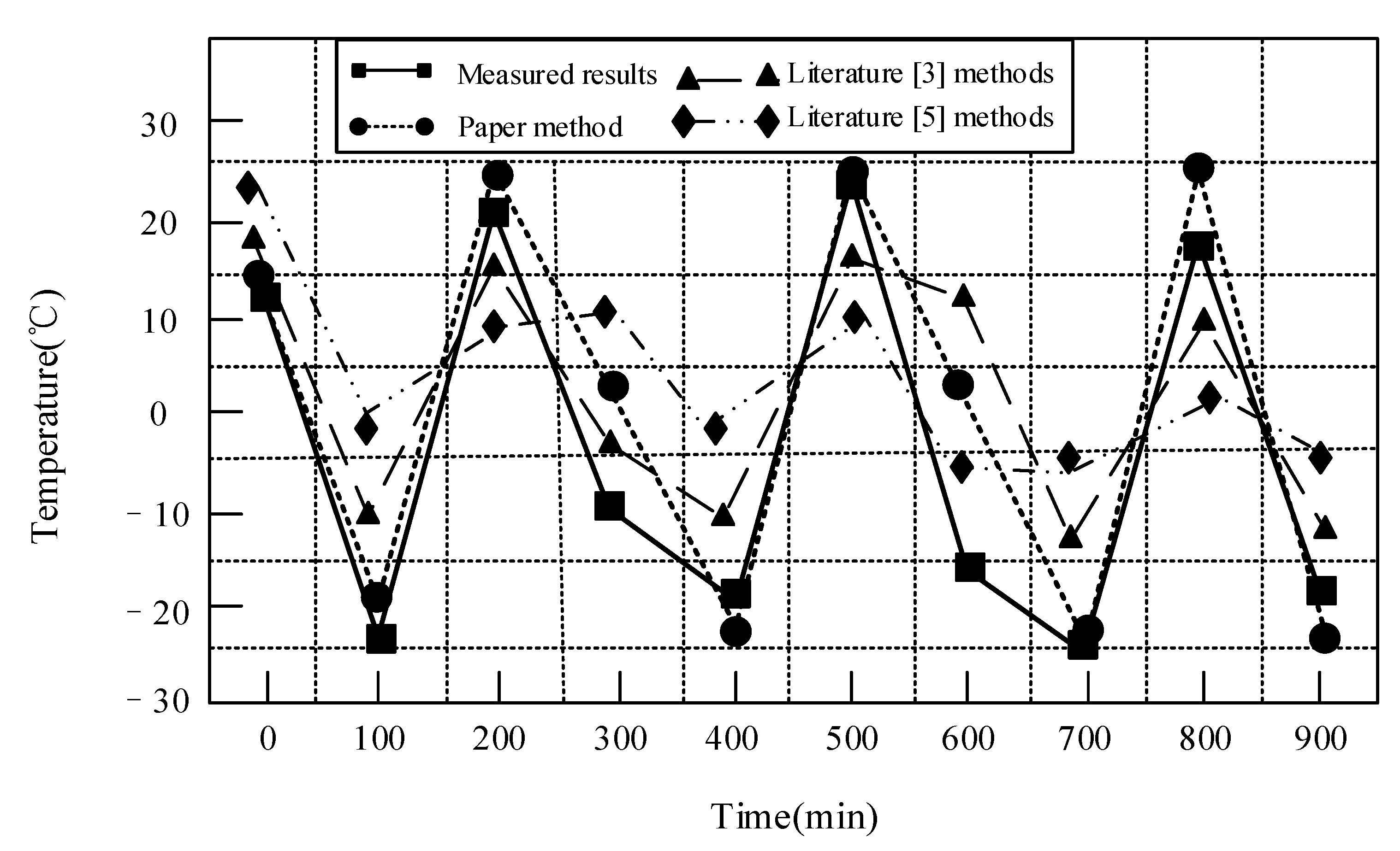
3.2. Experimental Analysis of Temperature Shock Field

Firstly, the temperature impact field test was carried out on the concrete specimen. The temperature measurement results of the key points of each structure are shown in Table 2.
According to the measured results in Table 2, the temperature fluctuation curve could be obtained. Because A, B and C were on the outer surface of the structure, the peak point was the largest, close to ±25 °C. The measured temperatures of the three key points were processed to obtain the average measured temperature curve. Compared with the measured temperature curve, the experimental results are shown in Figure 2.
As can be seen from Figure 2, compared with the other three methods, the temperature curve of the temperature impact field obtained by numerical simulation in this method was similar to the temperature curve measured by the actual test block, and had higher accuracy. Because the heat transfer process of concrete is time-dependent, it takes a period of time from the outer surface to the center point, so the temperature change of the inner center point and the time taken to reach the peak value are slightly delayed. In the process of heat conduction, with the continuous loss of heat, the temperature reaching the temperature sensor is far lower than the temperature of the outer surface. In the numerical simulation, the concrete material was set to be uniform, and the temperature curve obtained by heat conduction was consistent with the set curve. However, the internal material of the test block used in the test process was uneven. The addition of aggregates such as the superplasticizer increases the thermal conductivity of the test block, and the temperature curve lags behind relatively. This method can obtain the structure’s center’s temperature through numerical simulation, so as to better reduce the temperature change of the core in the test block during freezing and thawing. Therefore, the numerical simulation method proposed in this paper can simulate the influence of the temperature field on concrete durability, and has certain feasibility.

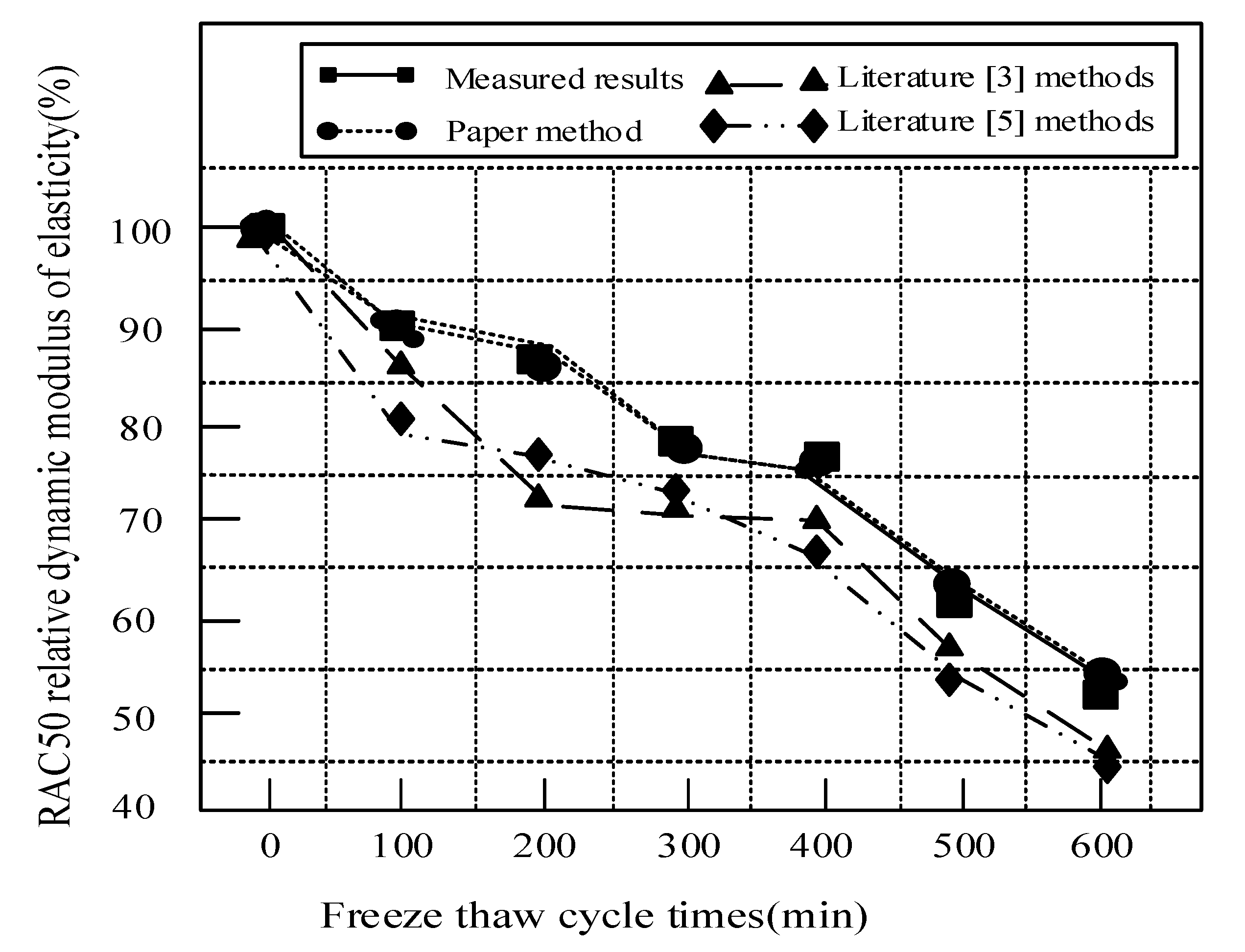
3.3. Experimental Analysis of Relative Dynamic Elastic Modulus

Then, the relative dynamic elastic modulus of concrete was tested, which was used as the physical damage index to measure the degree of freeze–thaw damage. The relative dynamic elastic modulus of different concrete types under different freeze–thaw cycles is shown in Table 3.
According to the data in Table 3, under the action of 300 freeze–thaw cycles of NAC concrete, the dynamic elastic modulus of the specimen decreases to 61.3% of the initial dynamic elastic modulus, and under the action of 310 freeze–thaw cycles, the dynamic elastic modulus of the specimen reaches 60% of the initial dynamic elastic modulus; under 500 freeze–thaw cycles, the dynamic elastic modulus of RAC50 concrete is 60% of the initial dynamic elastic modulus; after 600 freeze–thaw cycles, the dynamic elastic modulus of RAC100 concrete is always greater than 60% of the initial dynamic elastic modulus. Comparing the three numerical simulation methods with the actual values in Table 2, the fitting degree between the three numerical simulation methods and the actual values can be obtained, as shown in Figure 3, Figure 4 and Figure 5.
From Figure 2 to Figure 4, compared with the other two numerical simulation methods, the design method in this paper has a higher fitting degree with the actual value, and the maximum error is no more than 3%. The NAC sample can reach 60% within 310 min because of the characteristics of the NAC sample. Therefore, it can be seen that the design method in this paper can improve the accuracy of the analysis of the impact of the freeze–thaw cycle on concrete durability in a salt frost environment, and has a certain practical application value.

4. Conclusions

In order to improve the accuracy of the analysis of the influence of the freeze–thaw cycle on the durability of concrete in a salt freezing environment, the influence of the freeze–thaw cycle on the durability of concrete in a salt freezing erosion environment is numerically simulated in this paper. Firstly, considering the influence of the axial force and bending moment on the relationship between the bending moment and curvature, a concrete fiber beam column model is established. Then, according to the joint influence of the temperature field, stress field and seepage field on concrete in the process of freeze–thaw, the governing differential equation of the freeze–thaw cycle is established. Based on the coupling algorithm, the freeze–thaw damage section is divided, the non-uniform distribution of freeze–thaw damage is determined, and the division of the freeze–thaw damage section is completed. According to the linear relationship between freeze–thaw damage degree, relative dynamic elastic modulus, freeze–thaw cycle times and position variables, the durability of concrete is numerically simulated, and the attenuation law of bond strength at different section depths after freeze–thaw is determined. The results show that the temperature curve obtained by numerical simulation is consistent with the temperature curve measured by the actual test block, which can better reduce the temperature change of the inner core during freezing and thawing, the relative dynamic elastic modulus is in good agreement with the actual value, and the maximum error is no more than 3%. This provides a theoretical basis for solving the durability problem of concrete in a salt frost erosion environment and the optimal design of concrete structure. In order to better improve the accuracy of the impact analysis of the freeze–thaw cycle on concrete durability in a salt freezing environment, this paper will also improve the damage evaluation index of concrete under the influence of the freeze–thaw cycle in future research, so as to make the research more in-depth.

Author Contributions

Conceptualization, H.L. and H.G.; methodology, Y.Z.; validation, H.L.; formal analysis, H.G.; investigation, Y.Z.; resources, H.G.; data curation, Y.Z.; writing–original draft preparation, H.L.; writing–review and editing, H.L.; supervision, H.G.; project administration, H.L.; funding acquisition, H.L., H.G., Y.Z. All authors have read and agreed to the published version of the manuscript.

Funding

This research was funded by the Study on the Effect and Mechanism of Freeze–thaw Cycle on Concrete Durability in Saline Environment [NJZZ18044]; the Study on the Effect and Mechanism of Dry-Wet Freeze–thaw Cycle on Concrete in Saline Environment in Wuliangsuhai Area (BJ2015-2) and the Research on Concrete Durability in Saline Environment in Cold and Arid Regions of Inner Mongolia.

Institutional Review Board Statement

Not applicable.

Informed Consent Statement

Not applicable.

Data Availability Statement

Not applicable.

Acknowledgments

Thank you for all editors and reviewers.

Conflicts of Interest

The authors declare no conflict of interest.

References

  1. Zhang, Y. Seismic performance prediction simulation of bridge steel-concrete composite structure. Comput. Simul. 2020, 37, 480–483. [Google Scholar]
  2. Ji, Y.; Zhang, J.; Song, Q.; Zhu, H.; Shang, C. Effect of Nano-SiO2 on concrete performance in bittern corrosion environment. Bull. Chin. Ceram. Soc. 2019, 38, 1425–1432. [Google Scholar]
  3. Jiang, Z.W.; Li, L.J.; Zhang, Z.Y.; Yan, F.; He, P.; Niu, L. Analysis and application improvement of concrete freeze-thaw failure. Jiangsu Build. Mater. 2020, 174, 34–36. [Google Scholar]
  4. Huang, J.C.; Yang, K.K.; Hou, C.Y.; Ren, Z.J. Application of creto material in freeze-thaw damage repair of diversion channel lining slab concrete of Wannianzha pump station. Haihe Water Resour. 2020, 224, 66–67, 72. [Google Scholar]
  5. Fang, X.W.; Yao, R.F.; Yu, F.; Yu, J.W.; Yan, N.X. Effect of mix proportion parameters on concrete sulfate freeze-thaw damage. Int. J. Hydroelectr. Energy 2020, 233, 109, 129–132. [Google Scholar]
  6. Liu, N.; Chen, X.F.; Zhang, K. Cause analysis and countermeasures of freeze-thaw failure of thin-walled concrete members. Zhihuai 2019, 8, 42–43. [Google Scholar]
  7. Hou, Z.G. Repair and treatment of freeze-thaw damage of pier in tailrace of unit 5 of Wanjiazhai Water Control Project. Hydropower Autom. Dam Monit. 2019, 5, 93–96. [Google Scholar]
  8. Wang, J.B.; Niu, D.T. Study on the durability performance of shotcrete lining under coupling effect of nitric acid attack and freeze-thaw cycles (Part I): Deterioration law of performance and air-void structure. Mater. Rev. 2019, 33, 1340–1347. [Google Scholar]
  9. Peng, Y.Z.; Gao, J.; Xu, G.; Li, X. Prediction for corrosion life of reinforced concrete structures under salt freeze-thaw environment. Adv. Sci. Technol. Water Resour. 2019, 39, 44–49. [Google Scholar]
  10. Tian, Y.G.; Lu, D.; Wang, S.F.; Jia, K.; Wang, Z. Study on durability of C50 High performance concrete in the highway from Tongchuan to Huangling. Constr. Technol. 2019, 48, 20–24. [Google Scholar]
  11. Yang, X.M.; Sun, G.J. Experimental study on freeze-thaw damage depth of concrete in deicing salt environment. J. Nat. Disaster 2020, 29, 52–59. [Google Scholar]
  12. Huang, J.B.; Ning, B.K.; Li, M.S.; Xia, X. Analysis of freeze-thaw deterioration and damage characteristics of existing cracked concrete. Ind. Constr. 2020, 564, 146–151. [Google Scholar]
  13. Uur, B.; Toklu, H.Z. Effect of multi-cycle freeze-thaw tests on the physico-mechanical and thermal properties of some highly porous natural stones. Bull. Eng. Geol. Environ. 2020, 79, 255–267. [Google Scholar] [CrossRef]
  14. Xiaolai, Y.U.; Tian, R.; Xing, L.; Liu, Y. Modification of constrained concrete mechanics calculation model based on mander model. J. Yangzhou Univ. Nat. Sci. Ed. 2018, 21, 61–65. [Google Scholar]
  15. Truong, G.T.; Son, M.K.; Choi, K.K. Mechanical performance and durability of latex-modified fiber-reinforced concrete. J. Adv. Concr. Technol. 2019, 17, 79–92. [Google Scholar] [CrossRef] [Green Version]
  16. Brostow, W.; Chetuya, N.; Gencel, O.; Hong, H.J.; Menard, N.; Sayana, S. Durability of portland concrete containing polymeric fillers and fly ash. Mater. Sci. 2019, 26, 103–108. [Google Scholar] [CrossRef] [Green Version]
  17. Kandasami, S. Performance-based specification of concrete for durability: Carbonation-induced corrosion. Indian Concr. J. 2019, 4, 61–79. [Google Scholar]
  18. Raveesha, P.; Prakash, K.E.; Babu, B. Impact of salinity in Netravali estuary sand on durability of reinforced cement concrete. Indian Concr. J. 2019, 93, 27–33. [Google Scholar]
  19. Feo, L.; Ascione, F.; Penna, R.; Lau, D.; Lamberti, M. An experimental investigation on freezing and thawing durability of high performance fiber reinforced concrete (HPFRC). Compos. Struct. 2019, 234, 111673. [Google Scholar] [CrossRef]
  20. Ding, W.; Leng, L.; Wei, Q.; Zhang, X.; Zhou, Y.; Tian, G.; He, X.; Ji, X.; Wang, J. Introduction to code for mix proportion design of ordinary concrete (JGJ55–2011). Concr. World 2011, 12, 76–79. [Google Scholar]
Figure 1. OPENSEES interface.
Coatings 11 01198 g001
Figure 2. Experimental comparison results.
Coatings 11 01198 g002
Figure 3. Relative dynamic elastic modulus of NAC specimens with different methods.
Coatings 11 01198 g003
Figure 4. Relative dynamic elastic modulus of RAC50 specimens with different methods.
Coatings 11 01198 g004
Figure 5. Relative dynamic elastic modulus of RAC100 specimens with different methods.
Coatings 11 01198 g005
Table 1. Material parameters.
ParameterValueParameterValue
Conductivity (W/M·K)1.29Specific heat (J/kg·°C)0.2
Density (kg/m3)2.5Expansion angle40
Dynamic modulus of elasticity (Pa)2.486Eccentricity0.15
Poisson’s ratio0.2Strain loading ratee−2
Expand (1/°C)e−5Viscosity parametere−5
Table 2. Temperature measurement results of key points of the specimen structure.
Time (min)Point A Temperature (°C)Point B Temperature (°C)Point C Temperature (°C)
012.2613.6512.66
100−22.55−23.57−22.55
20020.8821.8220.87
300−9.62−9.26−10.24
400−18.29−19.32−19.32
50023.5524.9524.23
600−15.88−15.28−15.55
700−24.26−24.55−24.78
80018.3319.1218.52
900−17.62−18.43−18.24
Table 3. Relative dynamic elastic modulus of different concrete specimens under different freeze–thaw cycles.
Freeze Thaw Cycle TimesNAC (%)RAC50 (%)RAC100 (%)
0100100100
10070.7291.5397.04
20069.3886.9194.4
3006179.5690.42
40075.0387.47
5006084.17
60054.6182.8
Publisher’s Note: MDPI stays neutral with regard to jurisdictional claims in published maps and institutional affiliations.

