Article

Evaluation of Functionalized Coatings for the Prevention of Ice Accretion by Using Icing Wind Tunnel Tests

1
UPNA—Department of Engineering, Public University of Navarre, Campus Arrosadía s/n, 31006 Pamplona, Spain
2
INAMAT—Institute for Advanced Materials, Public University of Navarre, Campus Arrosadía s/n, 31006 Pamplona, Spain
3
AIN—Centre of Advanced Surface Engineering, 31191 Cordovilla, Spain
4
AIMPLAS—Instituto Tecnológico del Plástico, València Parc Tecnològic, Calle Gustave Eiffel 4, 46980 Paterna, Valencia, Spain
5
INTA—Instituto Nacional de Técnica Aeroespacial, Área de Materiales Metálicos, Ctra. Ajalvir Km 4, 28850 Torrejón de Ardoz, Spain
*
Author to whom correspondence should be addressed.
Coatings 2020, 10(7), 636; https://doi.org/10.3390/coatings10070636
Submission received: 15 May 2020 / Revised: 24 June 2020 / Accepted: 29 June 2020 / Published: 30 June 2020
(This article belongs to the Special Issue Anti-Icing Coatings and Surfaces)

Abstract

:
Ice accretion presents serious safety issues, as airplanes are exposed to supercooled water droplets both on the ground and while flying through clouds in the troposphere. Prevention of icing is a main concern for both developers and users of aircraft. The successful solution of this problem implies the combination of active and passive methods and the use of advanced sensors for early detection of icing and monitoring of ice accretion and de-icing processes. This paper focuses on the development of passive solutions. These include advanced anti-icing coatings deposited by a variety of chemical methods including sol-gel, advanced paints based on polyester combined with fluorinated derivatives and applied by electrostatic spray deposition and conventional silicone-based paints modified by adding alumina nanoparticles. Water contact angle has been measured in all cases, demonstrating the hydrophobic character of the coatings. An ice accretion test has been carried out in a laboratory scale icing wind tunnel (IWT) located in a cold climate chamber. Three different studies have been undertaken: ice accretion measurement, durability of the anti-icing behavior after several icing/de-icing cycles and ice adhesion testing by means of the double lap shear test (DLST) methodology. All the studied coatings have shown significant anti-icing behavior which has been maintained, in some cases, beyond 25 cycles. Although these results are still far from any possible application for aeronautic components, they provide interesting insights for new developments and validate the laboratory scale tests.

1. Introduction

Ice accretion presents serious, sometimes catastrophic, safety issues for aircraft, due to the presence of supercooled water droplets under specific atmospheric conditions, both on the ground and while flying through clouds in the troposphere [1,2]. In the last decades, hundreds of incidents due to icing have been reported. Many have led to aircraft crashes with a high rate of mortality [3]. This is not an issue only for extreme latitudes, but a ubiquitous problem that can appear anywhere. A significant example is a recent aircraft icing episode near Madrid in 2017 as described by Bolgiani et al. [4]. It has been demonstrated that flight performance can be seriously affected by ice accumulated on several critical areas [5,6]. For example, icing in the horizontal tail stabilizer can reduce its ability to balance the tendency of the nose to pitch downward, potentially leading to a phenomenon called tail stall. In addition, ice accumulation on wings disrupts the airflow by altering the shape of the wing surface. This leads to increased drag and decreased ability to create lift. Several tests such Icing Wind tunnel (IWT) and flight tests [7] have shown that an ice layer with the thickness of a piece of coarse sand paper can reduce the lift and increase considerably the drag [8,9]. Extensive effort has been devoted to study this crucial yet challenging issue. Icing reduction can be achieved by two different strategies: de-icing and anti-icing corresponding respectively to active and passive approaches. The de-icing strategy (active methods) involves chemical [10,11], thermoelectric [12,13], or mechanical methods [14,15] for removing ice that has already accumulated. If previously activated, when possible, it helps to avoid/reduce ice accretion. De-icing systems exhibit inherent negative effects such as high-power consumption along with a complex and continuous maintenance, an increase of weight, and the need to frequently reapplicate chemicals. These increase the design, fabrication and operation costs and have important negative environmental consequences [16,17,18].
Passive methods have been used in order to avoid ice accretion or facilitate detachment once ice has been formed. Hydrophobicity has been traditionally used as an initial strategy when designing icephobic surfaces, based on the idea that a nonwetting material repels droplets and avoid ice formation [19,20]. Extensive research has been carried out on the development of superhydrophobic properties applied to anti-icing materials [21]. Superhydrophobic surfaces are based on the lotus flower effect [22] by combining wax-like nonpolar substances together with a defined hierarchical roughness. This effect allows flowers and leaves to be kept dry and clean, even in muddy water.
Superhydrophobic surfaces exhibit contact angles (CA) higher than 150° and high water repellency, thus causing droplets to bounce. To achieve this effect, it is necessary to combine suitable chemical properties using hydrophobic materials and physical properties based on the generation of specific structures composed by hierarchical levels of roughness from micro to nanostructures. These structures tend to form a microscopic air film (Cassie-Baxter) on the droplet solid-water interface, reducing the interaction of liquid with the surface so that the droplet can easily roll over the surface [23,24]. It has been demonstrated that this correlation is not always true as in very humid environments ice forms in superhydrophobic materials [25,26,27,28]. Although roughness yields to hydrophobicity, the presence of micro- and nano-cavities can promote nucleation and formation of ice crystals. In addition, small microcracks and fractures can appear on the surface and can also lead to additional nucleation sites limiting the use of superhydrophobic surfaces. Under some conditions, this type of surface increases ice adhesion, thus reducing the anti-icing effect of these materials [29].
To prevent ice formation, water droplets should be quickly evacuated from the surface to avoid freezing [30]. This could be achieved by reducing the surface energy and improving hysteresis angles without greatly affecting nanoroughness. To carry out these modifications, the most used strategy is to adjust or reduce surface energy by applying coatings or adding materials. Materials with low surface energy could be used directly on the surface or to modify commercial coatings. Some examples include fluorinated polymers, polydimethylsiloxanes (PDMS), paraffin type, or inorganic materials deposited by PVD, CVD, or sol-gel based on functionalized silicas by organosilanes.
Most of the known anti-icing materials are soft polymers. Critical drawbacks are their durability due to icing cycles, wear, and erosion (rain or particle) among others, despite some promising results in elastomeric polymers [31] or polytetrafluoroethylene coatings [32,33]. Due to this, several works are focused on the design and fabrication of durable icephobic polymeric surfaces [34,35,36,37]. Recently some authors have studied the behavior of hard coatings by thermal spray for anti-icing purposes. Zhang et al. have applied stable super hydrophobic TiO2/h-BN composite coatings by suspension plasma spraying containing 15% BN [38]. Sharifi et al. have studied the hydrophobicity of sprayed TiO2, as well as its icephobicity and durability [39,40]. By studying different deposition parameters, they have been able to obtain uniform superhydrophobic (SPH) behavior on samples treated with stearic acid. Qiao and collaborators deposited hard Fe-based amorphous coatings deposited by using plasma spraying and have found that depending on the spray parameters, a wear resistant triple-level hierarchical surface morphology can be obtained [41]. When these coatings are impregnated with heptadecafluoro-1,1,2,2-tetrahydro-decyl-1-trimethoxysilane, SPH behavior is observed. Very recently Mora and collaborators have studied the behavior of quasicrystalline materials (QCMs) in icing conditions [42]. Some QCMs exhibit non-stick properties and are used for cookware with the advantage of scratch resistance. The authors have deposited AlCuFeCr QCMs by HVOF thermal spray and have found an ice accretion degree similar to that of PTFE in a laboratory scale IWT.
Wet chemistry methods constitute a different approach for the deposition of superhydrophobic coatings [43]. Sol-gel films deposited by dip coating were employed to obtain highly hydrophobic surfaces that also performed well against ice accretion. By using thermal treatments and corrosion inhibitors, these coatings can provide extra protection to the aluminum alloys employed as reference [44]. Alternative strategies using electrostatic spinning technique are a new method for fabrication of superhydrophobic surfaces. These coatings can be modified to combine hydrophobic properties with anticorrosive protection for aluminum alloys [45]. In addition to the development of active and passive methods, another critical issue in this field is the evaluation and validation of new systems since there is no standard test to assess the icephobicity. A wide variety of tests to measure adhesion and ice accretion are available, but there is no general agreement in terms of best practice or procedures. For ice adhesion, there are several tests based on the shear stress necessary to detach the formed ice (in unrealistic conditions) from the material [46], among which the most used are the zero degree cone test (ZDCT) [47] and the double lap shear test (DLST) [48]. Another type of tests is the cantilever/electroshaker type [49] in which the specimen is held at one end and subjected to vibration. A sensor detects the moment of detachment of the ice sheet, since there is a change in the rigidity of the specimen. This requires an IWT to accrete the ice prior to carrying out the test. Another family of adhesion tests under realistic conditions also requires an IWT to form ice. They are the centrifugal systems [33,50] in which the tangential force necessary to detach the formed ice is evaluated.
The main tool to evaluate ice accretion in the laboratory simulating realistic conditions is the IWT. Different configurations of cold accelerated air systems with open or closed circuits nebulize water at low temperature and boost them at high speeds towards the specimen. There is no standard, nor universally accepted test condition. Durability is also a critical issue. According to Airbus DS, the mean duration of flying in icing condition in a commercial aircraft conditions is 4.500 h, which implies about 36.000 icing events, or cycles. The proposed anti-icing solutions need to last at least a significant length of these estimations.
The present paper reports the use of three alternative passive methods that employ coatings based on a soft hydrophobic matrix. The first coating is based on sol-gel dip-coating technology in order to fabricate thin-films with the presence of fluorinated polymeric chains in the outer surface which show a highly hydrophobic behavior. The second coating is based on additivated silicone paints with inorganic nanooxides and was chosen as the application method is simple and reproducible. The inorganic nanoparticles increase the wear resistance of the coating to erosion phenomena and the silicone matrix exhibits high chemical resistance to different kinds of fuels or lubricants usually employed in aircrafts and an improved behavior with temperature. Other advantages lie on its reparability and lightness. The third coating combines fluorinated modified silanes and polymers with low surface energy on a thermosetting polyester paint system. It was applied by electrostatic spray, which results in smooth surfaces, and low ice adhesion was expected.
Ice accretion tests of the three coatings were carried out in a laboratory-scale IWT with repeated icing/deicing cycles. In addition, ice adhesion was measured by the DLST and compared to reference substrate durability. The surface morphology of the coating’s surface was observed by scanning electron microscopy and the wetting properties were studied by WCA measurements both before and after exposing the samples to the IWT conditions in order to try to find an explanation for the observed results. PTFE and the base substrate were also tested for comparison purposes.

2. Experimental Section

2.1. Materials and Reagents

The reference substrate selected for the preparation of different coatings is aluminum alloy 6061-T6 (100 mm × 25 mm × 3 mm). The specimens were polished and cleaned with ultrapure water and dried prior to applying the coatings. The chemical reagents used for the sol-gel coatings were 1H,1H,2H,2H-Perfluorooctyltriethoxysilane (PFAS), ethanol (EtOH) (>99.5%) and hydrochloric acid (HCl) (37%) which were purchased from Sigma-Aldrich (St. Louis, MO, USA). For the modified silicone paints, Aeroxide Alu C805 nanoparticles from Evonik (Essen, Germany) and silicone paint R-2180 from NuSil (Carpinteria, CA, USA) were purchased. Primer SP-120 from NuSil was also used in order to increase the final adhesion of the modified coatings to the metallic substrate. The powder-coating for the electrostatic spray deposition was provided by Adapta Color S.L. (Castellón, Spain).
PTFE plate (thickness of 3 mm) was acquired from J. Morell S.A (Tarragona, Spain) to be used as reference material.

2.2. Coating Fabrication Techniques

Three different representative coatings have been applied by using the following fabrication techniques:

2.2.1. Sol-Gel by Dip-Coating

The sol-gel coating was produced by mixing perfluoroalkyl silane (PFAS), aqueous hydrochloric acid (0.1 M HCl) and ethanol. The sol was prepared by mixing PFAS, 0.1 M aqueous HCl and EtOH in a specific molar ratio of 1:5:4.25, respectively, with an aging time of 1 day. Once, the sol-gel has been aged for this period of time, the sol-gel coatings were applied to the reference substrate (6061T6) using a programmable robot ND-R Rotatory Dip coater provided by Nadetech Inc. (Pamplona, Spain). The dipping speed (100 mm/min for immersion and withdrawal) as well as in the resultant immersion time (300 s for each dip deposition) was strictly maintained. A further thermal treatment at 180 °C was carried out overnight to eliminate excess solvent and to induce chemical cross-linking between the metal alkoxydes with the decrease of free hydrophilic hydroxyl groups (–OH) in the sol-gel matrix [51]. This thermal treatment offers a significant benefit. Harder films with very good adhesion were obtained [52] without decomposing the fluorinated chains of alkoxyde precursor located on the outer surface [53]. More details about the fabrication process can be found in [54].

2.2.2. Silicone Spray-Coating

To obtain superhydrophobic surfaces, the additivation of hydrophobic paint with inorganic oxide nanoparticles was carried out. A commercial silicone paint that exhibits hydrophobic behavior was selected (NuSil R2180), and alumina nanoparticles (Aeroxide, Evonik supplier) were introduced. Alumina nanoparticles with a high specific surface and a specific mean diameter of 15–20 nm were ultrasonically dispersed in an organic medium (xylene) with a sonotrode Hielscher (1000 W, 20 Hz) with the maximum amplitude (100%_25μ) for 30 min using a water bath to control the final temperature during the application of ultrasound. Subsequently, the dispersion was mixed with the silicone paint. The corresponding volume of silicone paint was calculated considering the content of Volatile Organic Compounds (VOCs) in the paint (80% in weight) to tailor the final concentration of alumina nanoparticles in the coatings. Prior to the deposition of the modified paint, different surface treatments were applied to the substrate with the aim of optimizing adhesion of the nanocomposite (modified paint) to the substrate. First, mechanical abrasion was applied to the substrate to increase the roughness in order to facilitate mechanical bonding of the paint. Next, an intermediate bonding layer (unmodified silicone paint) was sprayed. Then, the mixture of silicone paint with alumina nanoparticles in xylene was sprayed. The deposited nanocomposite was dried and cured in a vacuum muffle at 150 °C.

2.2.3. Electrostatic Spray Deposition

A test bar made of aluminum was powder-coated by electrostatic deposition provided by Adapta Color. The powder coating was based on polyester paint systems, combined with fluorinated derivatives and additives based on modified silanes. These ingredients were mixed in a molten state, cooled and crushed into a uniform powder. An electrostatic spray deposition (ESD) then deposited of the powder coating was done on the aluminum substrate. The spray gun applied an electrostatic field of 50 to 100 kV. After application of the powder coating, the test bar was cured overnight by using an oven at 80 °C, where the coating reacted chemically to produce long molecular chains, resulting in high cross-linking density.

2.2.4. Surface Characterization

The hydrophobic behavior of the coatings was evaluated by using a CA measuring apparatus (CAM 100 KSV Instruments, Burlington, VT, USA). The corresponding static CA value was obtained by using the tangent method algorithm. The final value was obtained after performing five measurements of the coated surface.
The surface morphology of the coatings was analyzed using a HITACHI S4800 field emission scanning electron microscope (FE-SEM, Hitachi High-Technologies Corporation, Tokyo, Japan). The roughness was measured by means of a Wyco RST-500 interferometric profilometer (Veeco Corporate, Plainview, NY, USA). Measurements were carried out using the vertical scanning interferometry (VSI) mode. The vertical resolution using this mode is 3 nm. Three-dimensional (3D) images of the surfaces were obtained, and the corresponding changes in Ra (surface roughness average) were measured.

2.3. Description of the IWT Tests

INTA’s laboratory-scale IWT allows simulating icing “in cloud” conditions in studies of active and passive ice protection systems as well as ice detection. It consists of an open section wind tunnel (see Figure 1), located inside a 54 m3 cold climate chamber offering temperature stability during long duration tests. A representative scheme of the test cell and the test conditions inside of the chamber are shown in Figure 1. The precooled samples (100 × 25 × 3.3 mm3) were affixed to the center of the test chamber (15 × 15 cm2 section), with the coated face perpendicular to the air flow. The exposed area was 8.75 cm2. The tests simulating glaze icing (see Figure 2) were carried out following experimental conditions in the IWT test chamber employing a nebulization time of 90 s.
Air speed was measured using a Pitot probe PCE-PFM 2 taking representative values in the testing area. The probe measuring range is 1 to 80 m/s, with 2.5% accuracy. The MVD of the nebulized droplets which is defined by the American Meteorological Society as: “A measure of the diameter that contributes most to cloud liquid water or mass,” was determined using a Malvern Spraytec system (see Figure 3), equipped with a 300 mm lens to measure droplet diameters from 0.1 to 900 μm, and determine MVDs from 0.5 to 600 μm in sprayed atmospheres, with >1% accuracy.
Two different studies were undertaken employing the IWT:
(1).
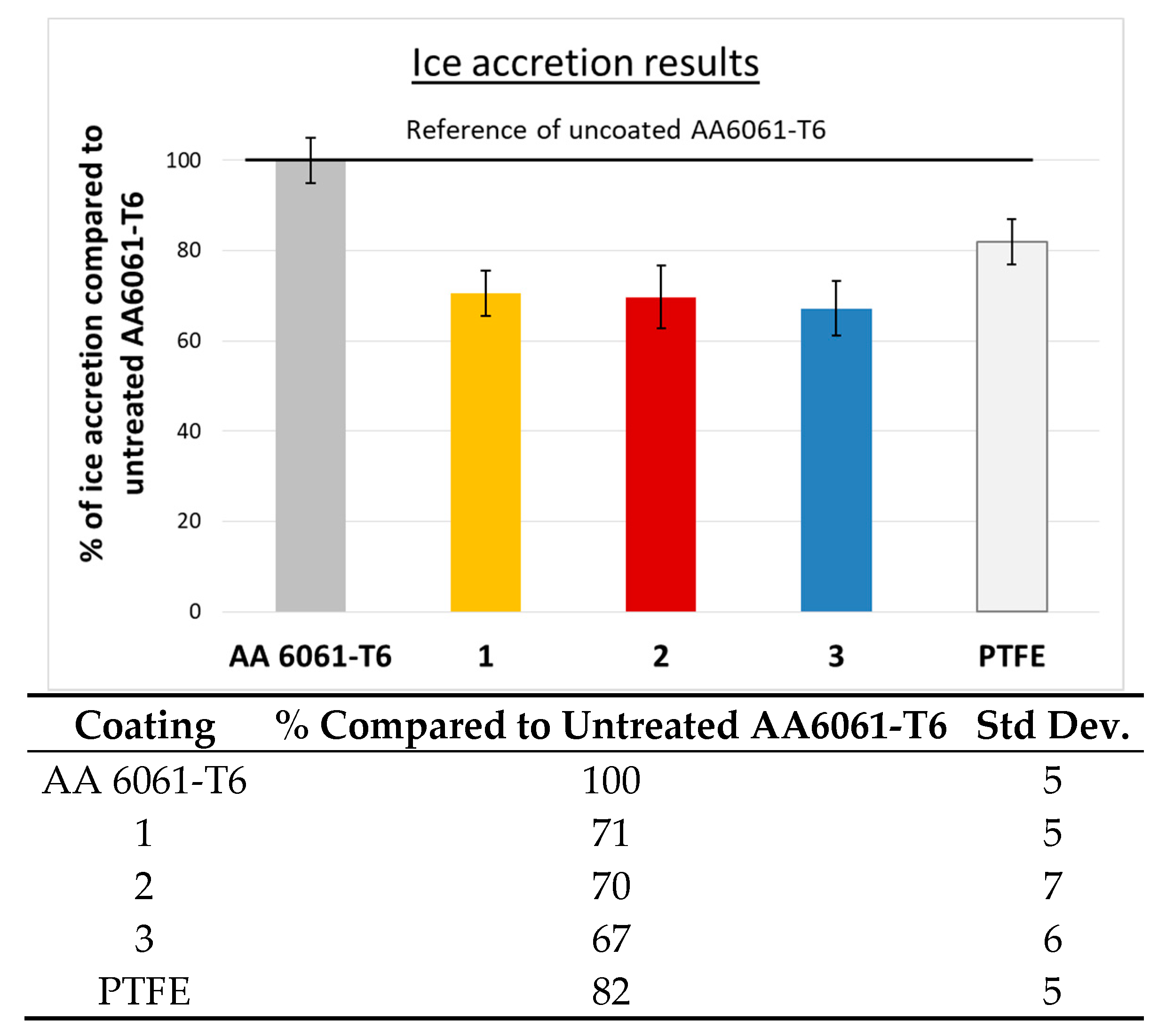
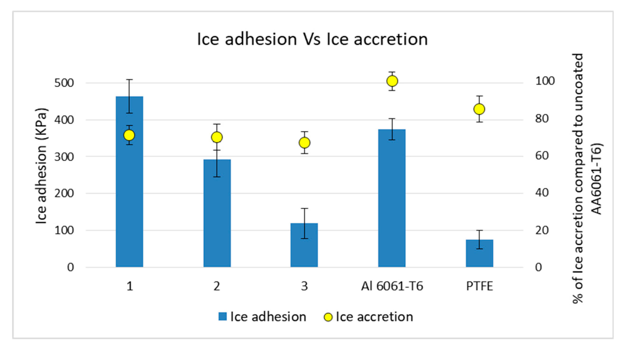
Ice accretion of deposited coatings: obtained by the weight difference caused by ice deposition employing a Sartorius TE153S laboratory balance (150 ± 0.001 g). This was repeated 6 times allowing time for the ice to melt at room temperature between each icing cycle to avoid any damage caused by the mechanical remove of ice. The mean value and standard deviation were obtained. The mass of accreted ice in every sample is compared with the mass accreted in the substrate of the reference, in this case, AA6061-T6, and the result was given as the percentage relative to the uncoated reference (see Equation (1)). The lower the ratio, the better the obtained anti-icing behavior.
%   of   ice   accretion = Mass   of   ice   accreted   in   sample   ( mg ) Mass   of   ice   accreted   in   AA 6061 T 6   ( mg ) × 100
(2).
Durability of anti-icing behavior after icing/de-icing cycles: in order to evaluate the loss of icephobicity caused by the processes of icing/de-icing. The different coatings were exposed to a sequence of icing/deicing stages, each containing several cycles and the ice accretion was measured after 17, 25, and 33 cycles, progressively reducing the cycles between measurements stages as the coatings began to show increases in ice accretion. The results were again normalized with the AA6061-T6 reference, which did not exhibit further degradation during the cycle sequence.

2.4. Ice Adhesion by Double Lap Shear Test (DLST)

An Instron 5882 Universal Machine (Barcelona, Spain) was used. It was equipped with a 5 KN loading cell, calibrated in the 5%–95% range and placed inside a climate chamber (refrigerated with liquid nitrogen). An ultralow temperature freezer (Arctiko ULTF series, Esbjerg, Denmark) was used to produce the ice layer on the surface of the coupons. The test procedure was as follows:
(1).
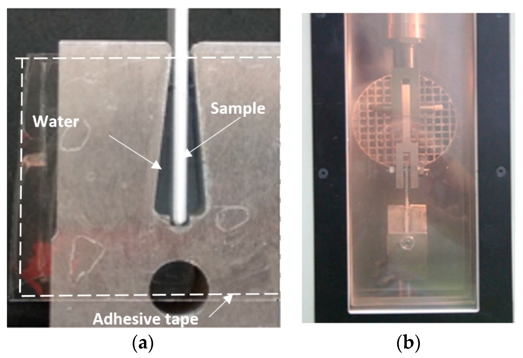
Mold preparation: Ice must be formed on the samples 24 h before the test. Initially, the sides of the test block were sealed with transparent adhesive tape to prevent water from escaping. The mold was then filled with water, ensuring that there are no air bubbles. The specimen was placed inside ensuring that the level of water on both sides of the specimen was the same, reaching 6 mm below the top edge of the mold (Figure 4).
(2).
Ice formation: The prepared molds were placed in a low temperature fridge at −10 °C (Arctiko ULTF series) and left for at least 16 h before the test.
(3).
Testing: One hour before the test, the adhesive tape was removed, and any remaining ice accreted over the sample edges was carefully, but quickly, removed by using a scalpel. The molds were placed in the freezer further for 1 h. The test block was fixed to the Universal Machine, which was previously cooled to the test temperature (Figure 4). The transport of samples from the freezer to the test rig was done very fast to maintain the temperature of the system. Once the selected test temperature was reached in the chamber, the samples were left for further 5 min before beginning the test. The displacement speed was set, and once the test was initiated, it continued until the sample was fully out of the mold.
(4).
Data evaluation: A plot of resultant measured load (N) as a function of displacement (mm) was obtained during the test. The maximum load peak corresponds to the load needed to overcome the adhesion strength and is a measure of the adhesion between ice and the surface of the sample in the corresponding testing conditions. Three specimens of each coating were tested to obtain the mean value and the standard deviation.

3. Results

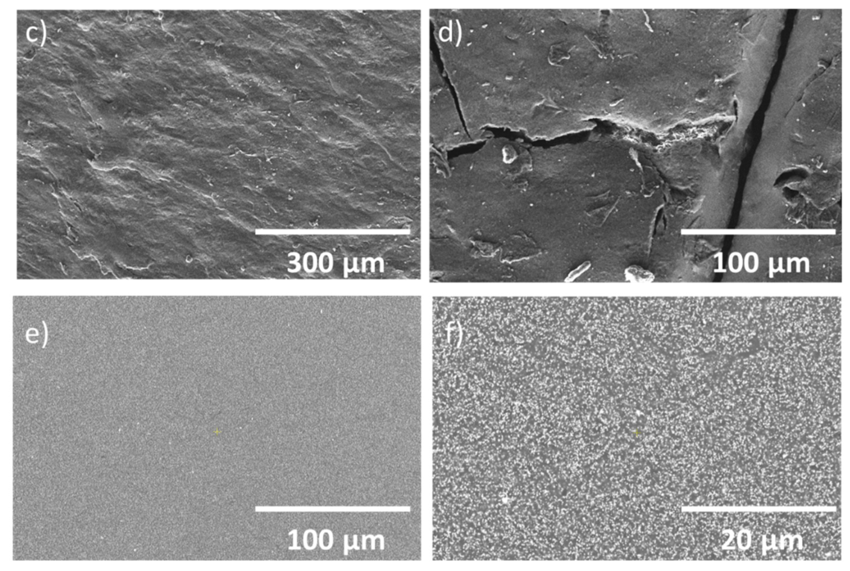
3.1. Surface Characterization of the As-Fabricated Coatings

Table 1 indicates the static WCA, the roughness and the thickness of the coatings included in this study.
The sol-gel produced coating was denoted as Coating 1. A final number of 5 immersion steps were performed with the aim to obtain a hydrophobic surface with a WCA value of 119.2°. This water repellent behavior is associated with the presence of nonpolar perfluoroalkyl groups in the outer surface of the coating. A thermal treatment of the sol-gel coating (curing step) was carried out to increase the hardness of the coating, increase its adhesion, and improve the mechanical properties as a result of chemical cross-linking between the PFAS alkoxydes [53]. Figure 5 shows SEM images of the sol-gel coating surface Figure 5a,b after thermal treatment. The coating exhibited an irregular surface, and the substrate grinding marks could still be observed, which is not surprising given the very low thickness of this coating (2 µm). At higher magnification, circles could be observed, which resulted perhaps from the formed during deposition of the coating.
The second coating was obtained by silicone spray and was denoted as Coating 2. The concentration of alumina nanoparticles in the nanocomposite coatings ranged from 2.5% to 35% in weight approximately. The corresponding series of nanocomposites was first characterized measuring the surface roughness, the WCA, and by undertaking cross-hatch adhesion tests. Only the coating with 5% Al2O3 has been considered as the most promising in terms of hydrophobicity and good coating adhesion and was denoted as Coating 2. Figure 5c,d shows the SEM images of the surface with uniform coverage. However, at higher magnification in some areas some coating detachment as well as scratches could be observed.
The third coating was produced by electrostatic spray deposition and was denoted as Coating 3. The paint was formulated by Adapta Color S.L. (trade secret formulation) and contained surface energy modifiers. This coating was applied by electrostatic deposition of the powder paint and Figure 5e,f show the SEM images of the top view. The very smooth surface, confirmed by a very low roughness, exhibited a homogenous dispersion of the powder along the overall surface.

3.2. Ice Accretion of the Coatings in Pristine Conditions

Flat geometry specimens are not the best option for IWT tests, since accretion is highly influenced by edge effects which behave as ice nucleation sites artificially increasing the accreted ice weight. Nevertheless, a general decrease in ice accretion was observed, as shown in Figure 6. The best result was Coating 3, which decreased the ice accretion by 33% relative to the uncoated substrate. In any case, a high dispersion in the results was observed, which is common in IWT results. So, it can be concluded that the degree of ice accretion reduction was similar for all the studied coatings, and in all cases, lower than on PTFE.

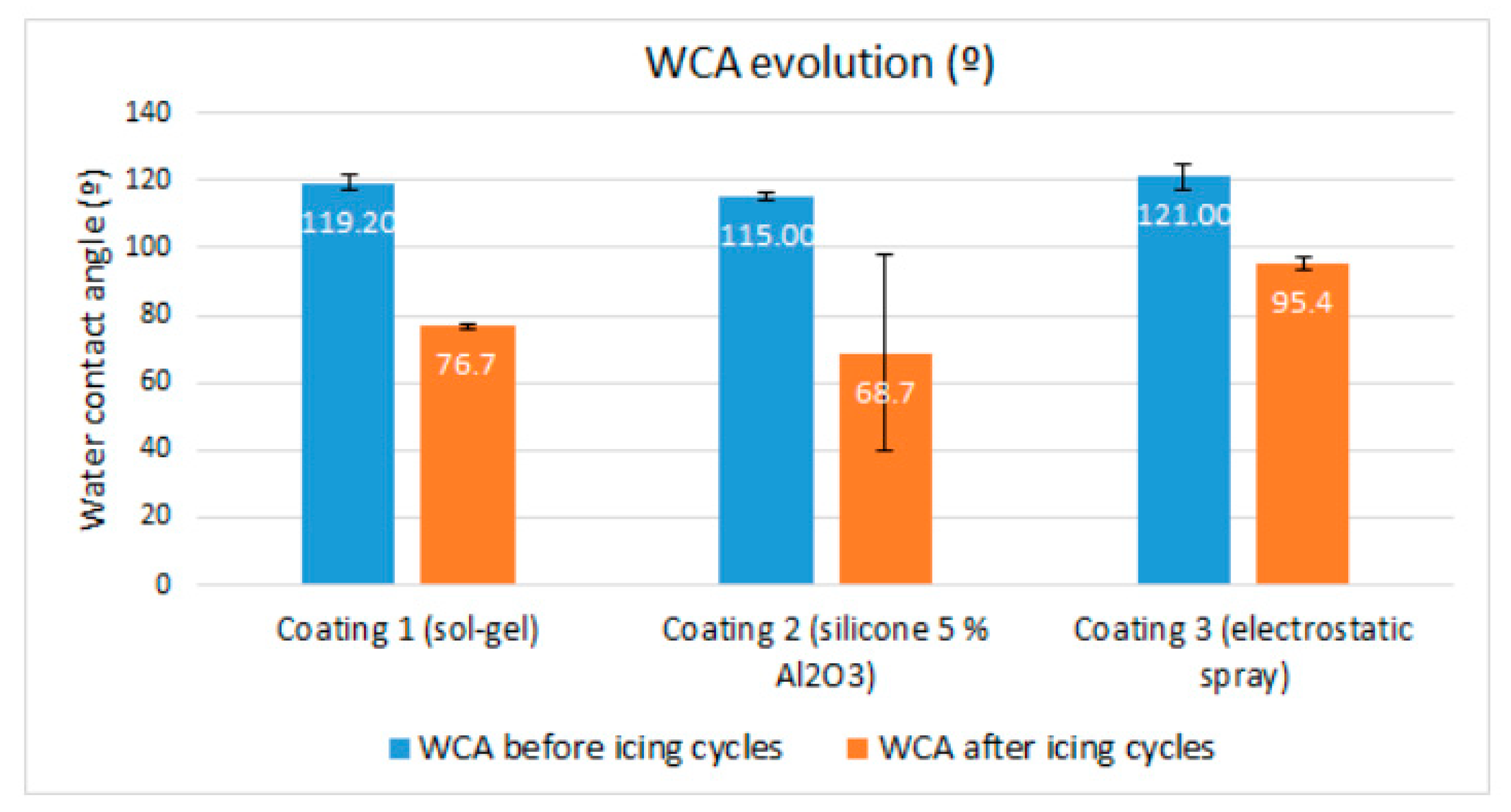
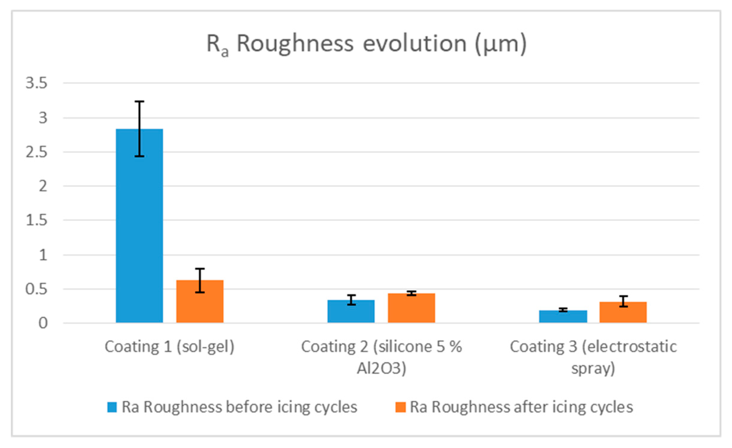
3.3. Durability of the Anti-Icing Behavior after Icing/De-Icing Cycles

The durability of anti-icing properties is a key factor in the aeronautic sector due to the exposure to severe environmental conditions. A pending issue is the lack of proper evaluation standards for reducing the ice accretion. Moreover, there is no standard for the evaluation of the durability related to icephobic coatings. In this work, an experimental test was designed to analyze the gradual degradation of the coatings, measuring ice accretion after stages comprising a certain number of cycles and reducing the number of cycles per stage as the coating anti-icing behavior began to deteriorate. Specifically, the test was stopped when a material reached the same accretion value as the untreated reference AA6061-T6, and therefore, no reduction of ice accretion was obtained. In all cases of study, the degradation of the properties during the test was observed, as it is shown in Figure 7.
The experimental results demonstrate that Coating 3 performed the best, keeping a slight ice accretion reduction after 25 cycles. Coating 2 also demonstrated good performance up to 17 cycles, after which, a sudden loss of ice reduction ability was observed. Coating 1 maintained its ice reduction property at 17 cycles, and it totally failed at 25 cycles. These results are still far from any possible application for aeronautic components, and both durability and ice accretion reduction of the present coatings need to be clearly improved in order to be considered as a real option for technological applications.
After completing the test, both the WCA and the roughness of the tested samples were measured again. Relevant decreases in WCA were observed in all coatings, as shown in Figure 8.
In contrast, only Coating 1 exhibited a substantial decrease in roughness as exhibited in Figure 9, where the roughness of all coatings before and after the icing/deicing cycling test are shown. There was a slight increase in roughness of Coatings 2 and 3.
To complete the durability study, the surfaces of the tested samples were re-examined by SEM microscopy in search of damages or any other defects that could explain the loss of the anti-icing behavior, as well the decrease in the WCA values and in the roughness levels for some of the coatings. Figure 10 shows the FESEM images before and after the icing/deicing cycling test.
Coating 1 clearly suffered degradation as shown in Figure 10a,d. When comparing with the initial surface, it seems as if the coating has been mostly removed and only the substrate with its corresponding grinding marks is left with only some coating residues. This sol-gel coating could have been eroded by the supercooled water droplets or alternatively detached due to the temperature cycles, and given its initial low thickness (<2 µm), it could have totally disappeared after a few icing/deicing cycles. The significant drops in both WCA (Figure 8) and roughness (Figure 9) support these hypotheses. This coating is, therefore, either not hard or not adhesive enough to withstand the very harsh conditions encountered in the IWT test.
Coating 2 also had a totally different aspect after the icing de-icing cycles but in this case the surface was mostly covered by the coating although some holes with sizes ranging from a few microns to >20 µm could be clearly seen. The coating was therefore eroded during the test but not totally as it has an original thickness of 20 µm. This coating was rather smooth in the as-deposited condition, and the roughness slightly increased after the test, perhaps due to the presence of the “holes”. The coating kept a low ice accretion after more cycles than Coating 1 and that is easily explained as the coating was not totally removed during the test. The “holes” could have appeared on the surface after a certain number of cycles and acted as ice nucleation sites and therefore more ice was accreted after 25 cycles (Figure 7). In parallel, the WCA experienced an important reduction, and the initially hydrophobic surface became hydrophilic with a WCA of 68.7° as shown in Figure 8. This is indicative of a modification of the surface energy of the paint caused by the harsh conditions encountered in the IWT. Therefore, although this coating is better than Coating 1, it is also not sufficiently durable.
The low surface roughness of Coating 3 was not significantly affected by the icing/deicing cycles, and the WCA after the test was lower but still indicated hydrophobic behavior. The coating exhibited a similar morphology than that of the as-deposited coating as seen in Figure 10c,f but some scratches were observed on the surface. These defects could act as ice nucleation sites explaining the deterioration of the anti-icing behavior. In this case, the scratches may not be a result of the cycling test, but have rather resulted from handling the specimens while weighting, or while fixturing and detaching them in the IWT testing chamber. This coating clearly exhibited a better behavior and does not seem so affected by the icing/deicing cycles, but nevertheless needs improvement as any coating on aeronautic surfaces must exhibit scratch resistance in order to provide durable anti-icing protection.

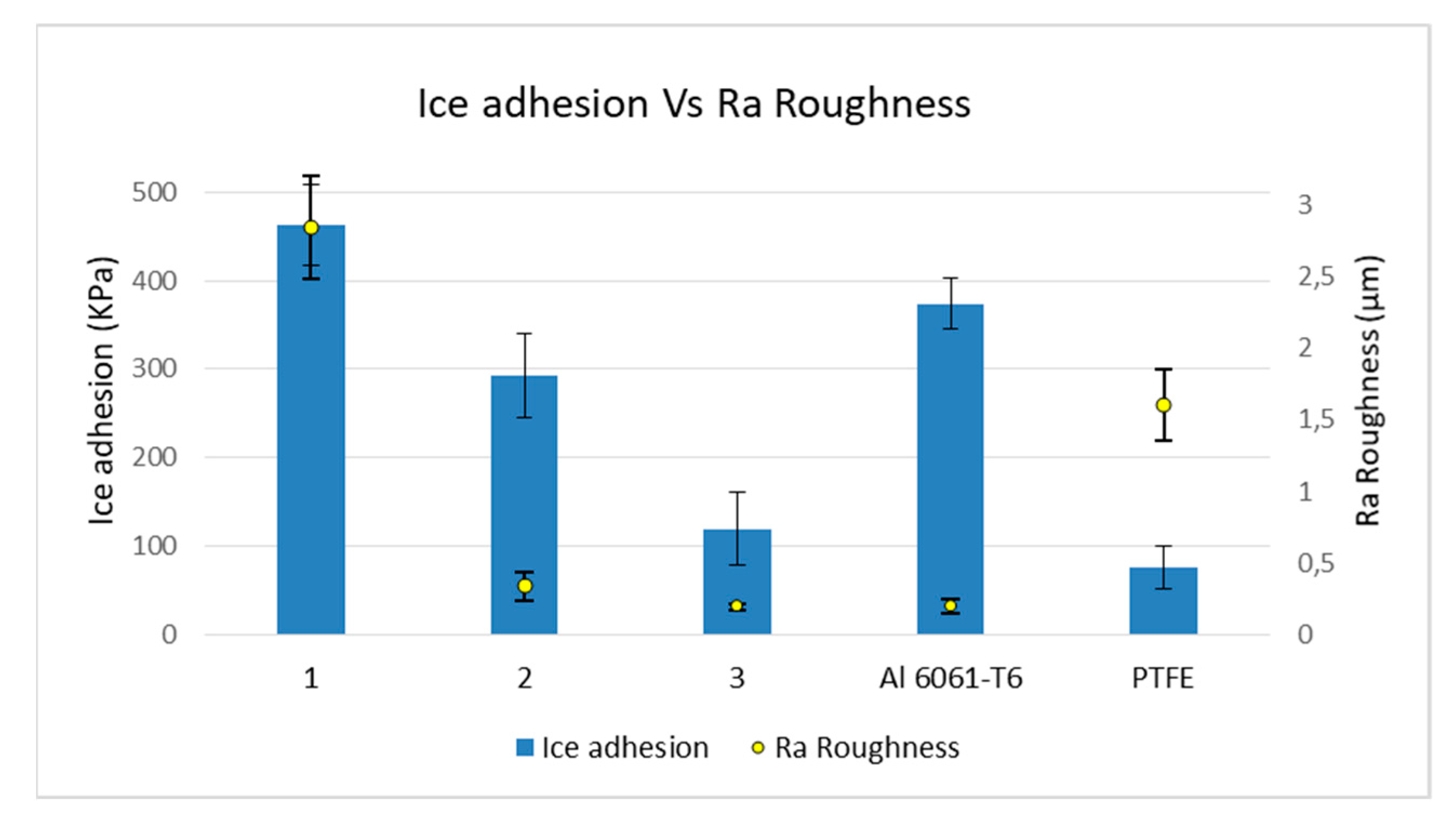
3.4. Ice Adhesion by the Double Lap Shear Test (DLST)

This test methodology was based on previous works [25,42] but was adapted to this specific application. Some modifications such as temperature range, loading rate, and the geometry of the molds have been implemented in order to obtain more reliable and consistent results. In addition, the test employs ice generated under static conditions (in a freezer) instead of in an IWT, resulting in advantages such as ease of execution, ease of interpretation of results, and simple specimen geometry. The results are shown in Figure 11, in which, the roughness of the different coatings has also been included. Two other materials have been included as references: untreated AA6061-T6 and PTFE, a polymer with a low ice adhesion as reported by many authors using different testing methodologies [32,55].
Ice adhesion mechanisms and the main adhesion contributor forces have been previously described, and summarized in four main effects: electrostatic interactions, van der Waals forces, hydrogen bonding, and mechanical interlocking due to solid surface roughness [56,57,58]. The first three effects are related to the chemical nature of the surface, whereas the last one is associated with the surface topography. Nonimpact ice formation methodologies, as the present one, are highly influenced by the surface topography and the interlocking effect. Chen et al. [59], among others, point out that the higher the roughness, the higher the ice adhesion. During slow freezing of water in this method, the growing ice crystals have time to fill the microgrooves and valleys present in the surface, increasing the contact area of the surfaces which results in an interlocking effect, thus, increasing adhesion. However, ice adhesion on PTFE was much lower than on AA6061-T6, despite the fact that AA6061-T6 exhibits low roughness (Ra = 0.2), whereas and PTFE is rougher (Ra = 1.6). This indicates that the composition effect (surface energy) has a higher impact in the ice adhesion of these two materials. The sol-gel coating (Coating 1) showed an ice adhesion order of magnitude higher than that exhibited by AA6061-T6. In this case, the very high roughness of this coating likely overcame the surface energy effects. On the other hand, from the three studied coatings, the electrostatic sprayed layer (Coating 3) achieved the lowest observed ice adhesion, probably caused by a suitable combination of low surface energy and low roughness. The high-quality surface of Coating 3, evidenced in Figure 5e,f, with uniform dispersion of the solid phase and the absence of defects, is key for obtaining low adhesion values. However, even with a lower roughness than PTFE, adhesion to ice was higher likely because of the effect of the surface composition. Finally, the silicone coating (Coating 2) exhibited lower adhesion than AA6061-T6, despite exhibiting similar roughness, therefore indicating the influence of the surface energy, but nevertheless adhesion was higher than that observed on Coating 3, with a similar roughness. The presence of surface defects such as those showed in Figure 5d may be behind this difference in behavior. These results clearly confirm that there is no clear correlation between iced adhesion and roughness.

4. Discussion

An anti-icing material must significantly delay or prevent ice accretion, or if it accretes, ice detachment should be easy. So far there are no reported passive solutions that have completely reached these objectives. The findings of this work are no different, nevertheless, slight improvements were observed and insights on the causes of failures had been provided. The three proposed coatings are all based on low surface energy materials of different compositions with different surface roughness. These materials achieved lower ice accretion rates than AA6061-T6, and even lower than PTFE. In addition, two of the three coatings showed lower ice adhesion than AA6061-T6, and one of them (Coating 3) exhibited a behavior very closed to that of PTFE in terms of low ice adhesion, as shown on in Figure 12. The experimental results indicate that Coating 3 was the best rated in ice accretion, ice adhesion and durability in ice accretion cycles, based on the presented methodologies. Failure in terms of lack of durability, was attributed to scratches present on the surface, indicating that the hardness of these materials needs to be increased. The failure mechanisms of the other two coatings regarding durability, were related to lack of coating adhesion and/or erosion resistance.
To date, a commercial passive solution that could be used without the simultaneous support of an active system is also not available. Passive solutions can help decrease the power required by active system by conferring further reduction in accretion and faster detachment which improves aircraft safety. Hybrid systems are being investigated by different groups. For instance, Strobl et al. combined electrothermal and thermomechanical active systems together with an ultrasmooth hydrophobic finish on AA2024-T3 and were able to decrease power consumption up to 91% in IWT tests [12]. Fortin et al. studied the required power supply using two commercial hydrophobic coatings applied over aluminum that covered National Advisory Committee for Aeronautics (NACA) profile, combined with a thermoelectric system. They achieved a 33% reduction in power consumption [60]. The coatings developed in this work could also be employed as a part of a combined active-passive system.

5. Conclusions

A comparative study based on the implementation of 3 alternative passive solutions designed to have anti-icing properties was performed. Wet-chemistry methods were employed to produce the coatings: (1) sol gel coatings, (2) conventional silicone-based paints modified by adding alumina nanoparticles and (3) advanced paints based on polyester combined with fluorinated derivatives applied by electrostatic spray deposition. In all three cases, WCA and roughness measurements were undertaken to measure of the hydrophobic behavior of the coatings and the surface topography respectively. Ice accretion tests were performed in a lab scale IWT by two different studies including ice accretion in pristine conditions and durability of the anti-icing behavior after icing-de-icing cycles. Ice adhesion was evaluated by using a DLST modified methodology. The polyester-fluorinated additive coating applied by electrostatic spray deposition exhibited the best behavior in ice accretion, ice adhesion and durability in ice accretion cycles with an overall better behavior than PTFE. Coatings 1 and 3 failure mechanisms in terms of durability, were attributed to lack of sufficient coating adhesion and/or erosion resistance, whereas in the case of Coating 3 surface scratching during sample manipulation seemed to be the main cause of failure.

Author Contributions

All the authors have participated in the Conceptualization, Methodology, and Investigation; P.J.R., J.M. and A.G. have participated in the Writing—Original Draft Preparation; P.J.R., R.J.R., J.M. and A.G. have participated in the Writing—Review and Editing, Visualization and Supervision. All authors have read and agreed to the published version of the manuscript.

Funding

This research was funded by the Ministerio de Ciencia, Innovación y Universidades-Retos (Project RTI2018-096262-B-C41–MAITAI, Multidisciplinary Approach for the Implementation of new Technologies to prevent Accretion of Ice on aircraft), and by the Public University of Navarre (Project PJUPNA1929).

Acknowledgments

AIMPLAS wish to thank to Adapta Color S.L. for their contribution supplying coating formulation during the project.

Conflicts of Interest

The authors declare no conflict of interest.

References

  1. Kim, P.; Wong, T.-S.; Alvareng, J.; Kreder, M.J.; Adorno-Martinez, W.E.; Aizenberg, J. Liquid-Infused Nanostructured Surfaces with Extreme Anti-Ice and Anti-Frost Performance. ACS Nano 2012, 6, 6569–6577. [Google Scholar] [CrossRef] [PubMed]
  2. Meuler, A.J.; Smith, J.D.; Varanasi, K.K.; Mabry, J.M.; McKinley, G.H.; Cohen, R.E. Relationships between Water Wettability and Ice Adhesion. ACS Appl. Mater. Interfaces 2010, 2, 3100–3110. [Google Scholar] [CrossRef] [PubMed]
  3. Cao, Y.; Tan, W.; Wu, Z. Aircraft icing: An ongoing threat to aviation safety. Aerosp. Sci. Technol. 2018, 75, 353–385. [Google Scholar] [CrossRef]
  4. Bolgiani, P.; Fernández-González, S.; Martín, M.L.; Valero, F.; Merino, A.; García-Ortega, E.; Sánchez, J.L. Analysis and numerical simulation of an aircraft icing episode near Adolfo Suárez Madrid-Barajas International Airport. Atmos. Res. 2018, 200, 60–69. [Google Scholar] [CrossRef]
  5. Ashenden, R.; Marwitz, J. Characterizing the Supercooled Large Droplet Environment with Corresponding Turboprop Aircraft Response. J. Aircr. 1998, 35, 912–920. [Google Scholar] [CrossRef]
  6. Politovich, M.K. Aircraft Icing Caused by Large Supercooled Droplets. J. Appl. Meteorol. 1989, 28, 856–868. [Google Scholar] [CrossRef] [Green Version]
  7. De Gregorio, F. Aerodynamic Performance Degradation Induced by Ice Accretion. PIV Technique Assessment in Icing Wind Tunnel; Springer: Berlin/Heidelberg, Germany, 2008; Volume 112. [Google Scholar]
  8. Whalen, E.; Broeren, A.; Bragg, M. Considerations for Aerodynamic Testing of Scaled Runback Ice Accretions. In Proceedings of the Collection of Technical Papers—44th AIAA Aerospace Sciences Meeting, Reno, Nevada, 9–12 January 2006; Volume 5, pp. 3170–3185. [Google Scholar]
  9. Abbas, A.S.; Khaleel, A.L. Study the effect of ice accretion on various aerodynamic flight characteristics using F-16 model. ARPN J. Eng. Appl. Sci. 2018, 13, 4687–4695. [Google Scholar]
  10. Mishchenko, L.; Hatton, B.; Bahadur, V.; Taylor, J.A.; Krupenkin, T.; Aizenberg, J. Design of Ice-free Nanostructured Surfaces Based on Repulsion of Impacting Water Droplets. ACS Nano 2010, 4, 7699–7707. [Google Scholar] [CrossRef]
  11. Ghalmi, Z.; Menini, R.; Farzaneh, M. Effect of Different Aluminium Surface Treatments on Ice Adhesion Strength; Scientific.Net: Baech, Switzerland, 2012; Volume 409. [Google Scholar]
  12. Strobl, T.; Storm, S.; Thompson, D.; Hornung, M.; Thielecke, F. Feasibility study of a hybrid ice protection system. J. Aircr. 2015, 52, 2064–2076. [Google Scholar] [CrossRef]
  13. Petrenko, V.F.; Sullivan, C.R.; Kozlyuk, V.; Petrenko, F.V.; Veerasamy, V. Pulse electro-thermal de-icer (PETD). Cold Reg. Sci. Technol. 2011, 65, 70–78. [Google Scholar] [CrossRef]
  14. Al-Khalil, K. Thermo-mechanical expulsion deicing system—TMEDS. In Proceedings of the Collection of Technical Papers—45th AIAA Aerospace Sciences Meeting, Reno, NV, USA, 8–11 January 2007; Volume 12, pp. 8562–8574. [Google Scholar]
  15. Schulz, M.; Sinapius, M. Evaluation of Different Ice Adhesion Tests for Mechanical Deicing Systems; SAE Technical Paper; SAE: Warrendale, PA, USA, 2015. [Google Scholar]
  16. Cornell, J.S.; Pillard, D.A.; Hernandez, M.T. Comparative measures of the toxicity of component chemicals in aircraft deicing fluid. Environ. Toxicol. Chem. 2000, 19, 1465–1472. [Google Scholar] [CrossRef]
  17. Ramakrishna, D.M.; Viraraghavan, T. Environmental Impact of Chemical Deicers—A Review. Water Air Soil Pollut. 2005, 166, 49–63. [Google Scholar] [CrossRef]
  18. Fay, L.; Shi, X. Environmental Impacts of Chemicals for Snow and Ice Control: State of the Knowledge. Water Air Soil Pollut. 2012, 223, 2751–2770. [Google Scholar] [CrossRef]
  19. Farhadi, S.; Farzaneh, M.; Kulinich, S.A. Anti-icing performance of superhydrophobic surfaces. Appl. Surf. Sci. 2011, 257, 6264–6269. [Google Scholar] [CrossRef]
  20. Antonini, C.; Innocenti, M.; Horn, T.; Marengo, M.; Amirfazli, A. Understanding the effect of superhydrophobic coatings on energy reduction in anti-icing systems. Cold Reg. Sci. Technol. 2011, 67, 58–67. [Google Scholar] [CrossRef]
  21. Yeong, Y.H.; Milionis, A.; Loth, E.; Sokhey, J.; Lambourne, A. Atmospheric Ice Adhesion on Water-Repellent Coatings: Wetting and Surface Topology Effects. Langmuir 2015, 31, 13107–13116. [Google Scholar] [CrossRef]
  22. Cao, L.; Jones, A.K.; Sikka, V.K.; Wu, J.; Gao, D. Anti-Icing Superhydrophobic Coatings. Langmuir 2009, 25, 12444–12448. [Google Scholar] [CrossRef]
  23. Kubiak, K.; Wilson, M.C.T.; Mathia, T.; Carval, P. Wettability versus roughness of engineering surfaces. Wear 2011, 271, 523–528. [Google Scholar] [CrossRef] [Green Version]
  24. Liu, Y.; Choi, C.-H. Condensation-induced wetting state and contact angle hysteresis on superhydrophobic lotus leaves. Colloid Polym. Sci. 2012, 291, 437–445. [Google Scholar] [CrossRef]
  25. Ferrick, M.G.; Mulherin, N.; Haehnel, R.; Coutermarsh, B.; Durell, G.; Tantillo, T.; Curtis, L.; Clair, T.S.; Weiser, E.; Cano, R.; et al. Evaluation of ice release coatings at cryogenic temperature for the space shuttle. Cold Reg. Sci. Technol. 2008, 52, 224–243. [Google Scholar] [CrossRef]
  26. Jung, S.; Dorrestijn, M.; Raps, D.; Das, A.; Megaridis, C.M.; Poulikakos, D. Are Superhydrophobic Surfaces Best for Icephobicity? Langmuir 2011, 27, 3059–3066. [Google Scholar] [CrossRef] [PubMed]
  27. Nosonovsky, M.; Hejazi, V. Why Superhydrophobic Surfaces Are Not Always Icephobic. ACS Nano 2012, 6, 8488–8491. [Google Scholar] [CrossRef] [PubMed]
  28. Kulinich, S.A.; Farhadi, S.; Nose, K.; Du, X.W. Superhydrophobic Surfaces: Are They Really Ice-Repellent? Langmuir 2011, 27, 25–29. [Google Scholar] [CrossRef] [PubMed]
  29. Ma, M.; Hill, R.M. Superhydrophobic surfaces. Curr. Opin. Colloid Interface Sci. 2006, 11, 193–202. [Google Scholar] [CrossRef]
  30. Frankenstein, S.; Tuthill, A.M. Ice Adhesion to Locks and Dams: Past Work; Future Directions? J. Cold Reg. Eng. 2002, 16, 83–96. [Google Scholar] [CrossRef]
  31. Golovin, K.; Kobaku, S.; Lee, D.H.; DiLoreto, E.T.; Mabry, J.M.; Tuteja, A. Designing durable icephobic surfaces. Sci. Adv. 2016, 2, e1501496. [Google Scholar] [CrossRef] [Green Version]
  32. Menini, R.; Ghalmi, Z.; Farzaneh, M. Highly resistant icephobic coatings on aluminum alloys. Cold Reg. Sci. Technol. 2011, 65, 65–69. [Google Scholar] [CrossRef]
  33. Kulinich, S.A.; Farzaneh, M. Ice adhesion on super-hydrophobic surfaces. Appl. Surf. Sci. 2009, 255, 8153–8157. [Google Scholar] [CrossRef]
  34. Golovin, K.; Dhyani, A.; Thouless, M.; Tuteja, A. Low–interfacial toughness materials for effective large-scale deicing. Science 2019, 364, 371–375. [Google Scholar] [CrossRef]
  35. Golovin, K.; Tuteja, A. A predictive framework for the design and fabrication of icephobic polymers. Sci. Adv. 2017, 3, e1701617. [Google Scholar] [CrossRef] [Green Version]
  36. Kreder, M.J.; Alvareng, J.; Kim, P.; Aizenberg, J. Design of anti-icing surfaces: Smooth, textured or slippery? Nat. Rev. Mater. 2016, 1, 15003. [Google Scholar] [CrossRef]
  37. Bahadur, V.; Mishchenko, L.; Hatton, B.; Taylor, J.A.; Aizenberg, J.; Krupenkin, T. Predictive Model for Ice Formation on Superhydrophobic Surfaces. Langmuir 2011, 27, 14143–14150. [Google Scholar] [CrossRef] [PubMed] [Green Version]
  38. Zhang, F.; Robinson, B.W.; De Villiers-Lovelock, H.; Wood, R.J.; Wang, S. Wettability of hierarchically-textured ceramic coatings produced by suspension HVOF spraying. J. Mater. Chem. A 2015, 3, 13864–13873. [Google Scholar] [CrossRef] [Green Version]
  39. Sharifi, N.; Pugh, M.; Moreau, C.; Dolatabadi, A. Developing hydrophobic and superhydrophobic TiO2 coatings by plasma spraying. Surf. Coat. Technol. 2016, 289, 29–36. [Google Scholar] [CrossRef]
  40. Sharifi, N.; Dolatabadi, A.; Pugh, M.; Moreau, C. Anti-icing performance and durability of suspension plasma sprayed TiO2 coatings. Cold Reg. Sci. Technol. 2019, 159, 1–12. [Google Scholar] [CrossRef]
  41. Qiao, J.; Jin, X.; Qin, J.-H.; Liu, H.-T.; Luo, Y.; Zhang, D. A super-hard superhydrophobic Fe-based amorphous alloy coating. Surf. Coat. Technol. 2018, 334, 286–291. [Google Scholar] [CrossRef]
  42. Mora, J.; García, P.; Muelas, R.; Agüero, A. Hard Quasicrystalline Coatings Deposited by HVOF Thermal Spray to Reduce Ice Accretion in Aero-Structures Components. Coatings 2020, 10, 290. [Google Scholar] [CrossRef] [Green Version]
  43. Rivero, P.J.; Garcia, J.A.; Quintana, I.; Rodriguez, R. Design of nanostructured functional coatings by usingwet-chemistry methods. Coatings 2018, 8, 2. [Google Scholar] [CrossRef] [Green Version]
  44. Maeztu, J.D.; Rivero, P.J.; Berlanga, C.; Bastidas, D.M.; Fernandez-Palacio, J.; Rodríguez, R.J. Effect of graphene oxide and fluorinated polymeric chains incorporated in a multilayered sol-gel nanocoating for the design of corrosion resistant and hydrophobic surfaces. Appl. Surf. Sci. 2017, 419, 138–149. [Google Scholar] [CrossRef]
  45. Rivero, P.J.; Yurrita, D.; Berlanga, C.; Fernandez-Palacio, J.; Rodríguez, R.J. Functionalized Electrospun Fibers for the Design of Novel Hydrophobic and Anticorrosive Surfaces. Coatings 2018, 8, 300. [Google Scholar] [CrossRef] [Green Version]
  46. Wang, C.; Zhang, W.; Siva, A.; Tiea, D.; Wynne, K.J. Laboratory Test for Ice Adhesion Strength Using Commercial Instrumentation. Langmuir 2014, 30, 540–547. [Google Scholar] [CrossRef] [PubMed]
  47. Bharathidasan, T.; Kumar, S.V.; Bobji, M.S.; Chakradhar, R.; Basu, B.J. Effect of wettability and surface roughness on ice-adhesion strength of hydrophilic, hydrophobic and superhydrophobic surfaces. Appl. Surf. Sci. 2014, 314, 241–250. [Google Scholar] [CrossRef]
  48. Ferrick, M.G.; Mulherin, N.D.; Coutermarsh, B.A.; Durell, G.D.; Curtis, L.A.; Clair, T.L.S.; Weiser, E.S.; Cano, R.J.; Smith, T.M.; Stevenson, C.G.; et al. Minimization of Ice Adhesion to Space Shuttle Component Surfaces. J. Adhes. Sci. Technol. 2012, 26, 473–503. [Google Scholar] [CrossRef]
  49. Javan-Mashmool, M.; Volat, C.; Farzaneh, M. A new method for measuring ice adhesion strength at an ice–substrate interface. Hydrol. Process. 2006, 20, 645–655. [Google Scholar] [CrossRef]
  50. Fortin, G.; Beisswenger, A.; Perron, J. Centrifuge adhesion tests to evaluate icephobic coatings. In Proceedings of the AIAA Atmospheric and Space Environments Conference 2010, Toronto, ON, Canada, 2–5 August 2010. [Google Scholar]
  51. Jeong, H.-J.; Kim, D.-K.; Lee, S.-B.; Kwon, S.-H.; Kadono, K. Preparation of Water-Repellent Glass by Sol–Gel Process Using Perfluoroalkylsilane and Tetraethoxysilane. J. Colloid Interface Sci. 2001, 235, 130–134. [Google Scholar] [CrossRef]
  52. Yu, Q.; Xu, J. Structure and surface properties of fluorinated organic–inorganic hybrid films. J. Sol-Gel Sci. Technol. 2011, 61, 243–248. [Google Scholar] [CrossRef]
  53. Wankhede, R.G.; Morey, S.; Khanna, A.; Birbilis, N. Development of water-repellent organic–inorganic hybrid sol–gel coatings on aluminum using short chain perfluoro polymer emulsion. Appl. Surf. Sci. 2013, 283, 1051–1059. [Google Scholar] [CrossRef]
  54. Rivero, P.J.; Maeztu, J.D.; Berlanga, C.; Miguel, A.; Fernandez-Palacio, J.; Rodríguez, R.J. Hydrophobic and Corrosion Behavior of Sol-Gel Hybrid Coatings Based on the Combination of TiO2 NPs and Fluorinated Chains for Aluminum Alloys Protection. Metals 2018, 8, 1076. [Google Scholar] [CrossRef] [Green Version]
  55. Karmouch, R.; Coudé, S.; Abel, G.; Ross, G.G. Icephobic PTFE coatings for wind turbines operating in cold climate conditions. In Proceedings of the 2009 IEEE Electrical Power and Energy Conference, EPEC, Montreal, QC, Canada, 22–23 October 2009. [Google Scholar]
  56. Menini, R.; Farzaneh, M. Advanced Icephobic Coatings. J. Adhes. Sci. Technol. 2011, 25, 971–992. [Google Scholar] [CrossRef]
  57. Ryzhkin, I.A.; Petrenko, V.F. Physical Mechanisms Responsible for Ice Adhesion. J. Phys. Chem. B 1997, 101, 6267–6270. [Google Scholar] [CrossRef]
  58. Petrenko, V.F. Study of the Surface of Ice, Ice/Solid and Ice/Liquid Interfaces with Scanning Force Microscopy. J. Phys. Chem. B 1997, 101, 6276–6281. [Google Scholar] [CrossRef]
  59. Chen, J.; Liu, J.; He, M.; Li, K.; Cui, D.; Zhang, Q.; Zeng, X.; Zhang, Y.; Wang, J.; Song, Y. Superhydrophobic surfaces cannot reduce ice adhesion. Appl. Phys. Lett. 2012, 101, 111603. [Google Scholar] [CrossRef]
  60. Fortin, G.; Adomou, M.; Perron, J. Experimental Study of Hybrid Anti-Icing Systems Combining Thermoelectric and Hydrophobic Coatings; SAE Technical Paper Series; SAE: Warrendale, PA, USA, 2011. [Google Scholar]
Figure 1. INTA’s laboratory scale IWT (a) and test chamber scheme including the employed test condition (b). LWC: liquid water content; MVD median volume diameter.
Coatings 10 00636 g001
Figure 2. Glaze ice deposited on an AA6061-T6 substrate in INTA’s IWT.
Coatings 10 00636 g002
Figure 3. Image of the Spraytec system attached to the IWT testing chamber (a) and droplet size distribution obtained under the experimental testing conditions (b).
Coatings 10 00636 g003
Figure 4. Test block employed to form ice on both sides of the sample (a) and block attached to the Universal Machine ready to start the test (b).
Coatings 10 00636 g004
Figure 5. Top view SEM images for the sol-gel coating at 500× magnification (a) and at 1000× magnification (b), for the silicone spray coating composed of 5% Al2O3 in weight at 180× magnification (c) and at 450× magnification (d), and for the electrostatic spray coating at 1000× magnification (e) and at 5000× magnification (f), respectively.
Coatings 10 00636 g005aCoatings 10 00636 g005b
Figure 6. Mean values and standard deviation after 6 ice accretion cycles for all the studied coatings.
Coatings 10 00636 g006
Figure 7. Evolution of ice accretion along the icing/de-icing cycles.
Coatings 10 00636 g007
Figure 8. Evolution of WCA before and after the Icing/de-icing cycles.
Coatings 10 00636 g008
Figure 9. Evolution of the surface roughness before and after the Icing/De-icing cycles.
Coatings 10 00636 g009
Figure 10. Top view SEM images for the at 500× magnification before the cycles: (a) sol-gel coating, (b) silicone sprayed coating, and (c) electrostatic sprayed coating; and after the icing cycles: (d) sol-gel coating, (e) silicone sprayed coating, and (f) electrostatic sprayed coating.
Coatings 10 00636 g010
Figure 11. Ice adhesion results versus roughness of the coatings of study.
Coatings 10 00636 g011
Figure 12. Ice adhesion versus ice accretion of the coatings of study.
Coatings 10 00636 g012
Table 1. WCA, thickness and roughness of the as-fabricated coatings.
Type of Coating WCA (°)Thickness (µm)Ra (µm)
Coating 1 (sol-gel)119.2° ± 2.3°1.92 ± 0.32.84 ± 0.4
Coating 2 (silicone 5% Al2O3)115.0° ± 1.1°20.0 ± 4.00.34 ± 0.07
Coating 3 (electrostatic spray)88.0° ± 4.0°75.0 ± 25.00.19 ± 0.02
AA6061-T689.8° ± 3.8°3000 (Bulk)0.17 ± 0.05
PTFE101.4° ± 5.1°3000 (Bulk)1.55 ± 0.61

