Article

Effect of Cellulose Microfiber Silylation Procedures on the Properties and Antibacterial Activity of Polydimethylsiloxane

by
Virginija Jankauskaitė
1,*,
Aistė Balčiūnaitienė
1,
Radostina Alexandrova
2,
Nijolė Buškuvienė
1 and
Kristina Žukienė
1
1
Department of Production Engineering, Kaunas University of Technology, 521424 Kaunas, Lithuania
2
Institute of Experimental Morphology, Pathology and Anthropology with Museum, Bulgarian Academy of Sciences, 1113 Sofia, Bulgaria
*
Author to whom correspondence should be addressed.
Coatings 2020, 10(6), 567; https://doi.org/10.3390/coatings10060567
Submission received: 16 May 2020 / Revised: 8 June 2020 / Accepted: 12 June 2020 / Published: 16 June 2020
(This article belongs to the Special Issue Non-Releasing Surfaces and Thin-Films with Antibacterial Properties)

Abstract

:
In this study, the liquid phase and vapor phase procedures for silylating cellulose microfibers by hexamethyldisilazane (HMDS) were compared in terms of efficiency. The influence of functionalization degree on the morphology of microfibers and their interaction with polydimethylsiloxane (PDMS) matrix has been investigated. The antibacterial properties of silylated cellulose microfibers hybridized with Ag nanoparticles, obtained by in situ chemical reduction, were also studied. Sample morphology investigations were carried out using spectroscopy and microscopy techniques (FTIR, XPS, TEM, SEM, EDS, XPS). Trimethylsilyl moieties appear on the surface of the cellulose microfibers after modification and improve the dispersibility of the microfibers, allowing strong interaction with the PDMS matrix and favoring its crosslinking density. Microfibers functionalized by the vapor phase of HMDS show smoother surfaces with higher concentrations of Si-containing groups, resulting in a more hydrophobic wetting behavior and a greater influence on the mechanical properties of the polymer. The silylated cellulose microfiber–Ag nanohybrid shows stronger antimicrobial activity towards Gram-positive and Gram-negative bacteria strains compared to that of the untreated hybrid. A PDMS composite loaded with this hybrid exhibits the ability to inhibit bacterial growth.

1. Introduction

Polydimethylsiloxanes (PMDSs) are the most widely used polymers in siloxane elastomers. Due to their distinctive properties, such as biocompatibility, good thermal and oxidative stability, high hydrophobicity and gas permeability, low surface energy, and nontoxicity, they are used in various fields [1,2,3]. PDMS, due to weather and UV stability, adhesiveness to various surfaces, inertness against food and living tissues, high optical clarity, biocompatibility, and biodurability, has also found widespread application in healthcare [4]. However, these polymers show poor mechanical strength and tear resistance due to an inherent weak interaction between PDMS chains, limiting broader application. In order to improve the mechanical properties of PDMS, a variety of fillers, such as graphite nanoplatelets and carbon nanotubes [3,5], carbon fibers [6], and organically modified nanoclay [7], have been used. The most efficient reinforcing filler is fumed silica [8]. The demand for natural reinforcements has been growing in recent years, prompted by environmental concerns and enabled due to their availability, price, and environmental aspects [9]. Cellulose fibers show promising results for use as additives in polymeric compositions due to their high strength, biodegradability, low density, renewability, nontoxicity, and easy surface chemical modification [10,11]. However, cellulose fibers are highly polar and hydrophilic; therefore, they cannot be uniformly dispersed in the nonpolar polymer matrices due to their agglomeration [12,13]. This causes a loss of polymer strength because of a weak load transfer from the matrix to the reinforcements. Consequently, cellulose surface modification is of interest in order to improve compatibility with a variety of polymer matrices [14]. Many chemical and physical treatments methods have been proposed for cellulose surface modification, including corona or plasma discharges [15], vacuum UV treatments [16], and chemical methods, which involve pretreatment of fiber surfaces by coupling agents (such as silanes and isocyanates) [17,18], grafting processes [19,20], and alkali treatments [21], among other methods.
Silane coupling agents are usually used to introduce silanol groups to the surface of cellulose and produce a hydrophobic surface [22]. Reactive silylating agents, such as chlorodimethyl isopropylsilane [23], dimethylchlorosilane [24], isocyanatepropyltriethoxysilane [25], and hexamethyldisilazane [26,27], are used in this procedure. Hexamethyldisilazane (HMDS) is an inexpensive, stable, and easily available compound [28]. The only by-product of a silylation reaction is ammonia, which is a notable advantage of this method. Although the handling of this reagent is easy, the low silylation power of HMDS and long reaction times are the main drawbacks to its application. Therefore, a catalyst can be used for activating this reagent. Mormann [27] described the silylation of microcrystalline cellulose with HMDS in ammonia as the reaction medium and with saccharin as the catalyst. Grunert and Winter [29] performed cellulose silylation with HMDS in formamide.
The modification of cellulose through silylation leads to improved hydrophobicity, thermal degradation, and reinforcement characteristics [17,30]. The procedure adopted to functionalize the cellulose surface may also produce a relevant influence on the final properties of the material [31]. The most common methods for modifying cellulose are liquid phase procedures, which involve the immersion of cellulose in the silylation agent solution [22,23]. Recently, vapor phase processes of organic/inorganic particles have been proposed. In this case, the material is modified by vaporizing the silane agent molecules under controlled temperature, which can generate smooth and more stable layers [31,32]. However, no research comparing the silylation effectiveness of the liquid phase and vapor phase methods has been found.
Silylation not onlys increases the interfacial adhesion between silicone elastomer and cellulosic filler but also favors the densification of the network [25,33]. Consequently, mechanical and thermal properties are enhanced. However, taking into account the potential medical applications, the development of silicones with antimicrobial activity is especially relevant. Incorporation of an antibacterial agent, such as silver nanoparticles (Ag NPs), by physical and chemical treatments or copolymerization is known to increase the antimicrobial properties of silicone elastomers [34,35,36]. Although Ag NPs possess a broad spectrum of antimicrobial, antifungal, and antiviral activity [37,38], they may cause inevitable harm to both human health and the environment, a limitation that greatly restricts their practical application [39,40]. To overcome this problem, Ag NPs have been generated in situ onto various organic/inorganic carriers [41,42]. Antimicrobial hybrids from cellulose and Ag NPs have also been extensively explored [43,44]. Different methods, such as physical (Ag NPs blending with cellulose without chemical reaction [13]), in situ chemical reduction (slow growth of Ag NPs inside of cellulosic material with or without chemical interaction [45]), and covalent bonding (i.e., encapsulated Ag NPs within dendrimers [46]), have been used for the combination of cellulose and Ag NPs. The products prepared by the physical method possess relatively weak Ag NPs adsorption on the surface and poor durability, while antimicrobial endurance of cellulosic materials containing Ag NPs is enhanced due to internal loading of nanoparticles within cellulose in the case of in situ chemical reduction [43]. The covalent bonding method ensures the permanent antimicrobial activity of immobilized Ag NPs on the cellulose.
The cellulose–Ag nanohybrids exhibit excellent antimicrobial activities against Gram-negative and Gram-positive bacteria [44,45]. Our investigations revealed the ability of the cellulose–Ag nanohybrid to grant silicone an antibacterial activity [47]. However, hydrophobization of cellulose particles blocks reactive end-groups on the surface and can influence its interaction with Ag NPs.
In this paper, we present an evaluation comparing the silylation of cellulose microfibers with hexamethyldisilazane by vapor phase and liquid phase procedures. The influence of the functionalization on microfiber morphology and microfiber interaction with silver nanoparticles and a polydimethylsiloxane matrix has been investigated. The in situ synthesized cellulose–Ag nanohybrid and PDMS/hybrid nanocomposites were also evaluated in terms of their antibacterial efficacy against different bacterial species.

2. Materials and Methods

2.1. Materials

PDMS Endeavour T-2516 (Endeavour Enterprise Co., Taiwan) was used for investigations. It is a room-temperature curing polymer supplied as a two-part system. Part A is a long-chain prepolymer (base) terminated with vinyl groups (CH2=CH–) and contains a platinum-based catalyst, while Part B is a short-chain crosslinker with Si–H groups. PDMS elastomer is formed through a crosslinking reaction of these parts at a mixing ratio of A:B = 1:1. The main properties of the PDMS used in this investigation are reported in [13]. Microfibers of cellulose (CF), a tough, fibrous polysaccharide that is insoluble in water and has a linear chain of glucose residues linked with β-1,4 bonds, were used. The microfibers were of medium length and had a moisture content of less than 10%. Liquid hexamethyldisilazane ((CH3)3SiNHSi(CH3)3, molecular weight 161.39 g/mol, purity 99.0%), anhydrous N,N–dimethylformamide (DMF) ((HCON(CH3)2, molecular weight 73.09 g/mol, purity 99.75%), and other chemicals were purchased from Sigma Aldrich and used as obtained.

2.2. Treatment of Cellulose Microfiber Surfaces

2.2.1. Silylation Methods

Two techniques for silylating CF powder with HMDS were applied.
  • Method I
A simple chemical vapor deposition technique was used to expose the CF particles to the HMDS vapor without using a catalyst at an elevated temperature for different periods. Here, 10 g of CF powder was placed on porous filter paper in a closed chamber containing an open vessel holding approximately 20 mL of liquid HMDS for 6–24 h at the temperature of 120 °C, using the setup shown in Figure 1a. Cellulose microfibers treated by vapor deposition are marked as CFvap.
  • Method II
A fully silylated powder was prepared by modification from the liquid phase, which was performed by soaking the CF powder in HDMS solution. Firstly, 10 g of CFs was dispersed in 100 mL of toluene for 30 min, and then 30 mL of HMDS was poured. Besides, 5 mL of DMF (catalyst) was added to increase the silylation reaction rate. The treatment was carried out by magnetic stirring for up to 24 h at a temperature of 175 °C, using the setup shown in Figure 1b. The HMDS-functionalized cellulose microfibers were thoroughly washed with acetone and then dried in a ventilated oven at 150 °C for 3 h. Cellulose microfibers treated in the liquid phase are marked as CFliq.
The changes in the chemical structure of the surfaces of cellulose microfibers after the silylation reaction are shown in Figure 1c. From the given molecular structure, it can be seen that cellulose is a homopolymer of d-anhydroglucopyranose monomeric units connected through β-1,4-glycosidic linkages [48]. During silylation, conversion of hydroxy to trimethylsiloxy groups occurs, which imparts hydrophobic properties to the cellulose microfiber surface. During silylation with HMDS, only NH3 is generated as a by-product.

2.2.2. Preparation of CF–Ag Nanohybrid

The CF–Ag nanohybrid was prepared through the reduction of Ag NPs in situ on the CF surface. Firstly, the appropriate amount (2 g) of polyvinylpyrrolidone (PVP) was dissolved in ethanol (8 g), and then CF powder (3 g) was mixed in this solution. Subsequently, AgNO3 solution in deionized water (0.2 g AgNO3 in 1 mL H2O) was introduced drop-wise with vigorous stirring for 1 h at room temperature. The reaction mixture firstly was sonicated for 15 min to produce a homogeneous nanocomposite mixture, and then it was stirred with a magnetic stirrer for up to 24 h at room temperature. After this period, the solution color changed from light yellow into yellowish-brown, indicating that PVP-stabilized Ag NPs had formed and their colloidal solution of ca. 5 mg/mL concentration in CH suspension was obtained. After this, the nanocomposite was filtered, washed with ethanol three times, and dried at 30 °C for 24 h to obtain the CF–Ag nanohybrid.

2.3. Preparation of Composites

Untreated or surface-treated CF particles were loaded in PDMS base prepolymer (part A) and dispersed by sonification for 15 min. Then, PDMS crosslinker (part B) was added under mechanical stirring. After dispersing the cellulose microfibers, PDMS/CF composite blends were degassed under vacuum for 60 min at room temperature to eliminate air bubbles, and they were further cured for 25 min at a temperature of 70 °C. During curing, the platinum-based catalyst catalyzed the addition of the Si–H bond across the vinyl groups, forming Si–CH2–CH2–Si linkages [49]. The reaction sites on both the prepolymer and crosslinking chains enhance the crosslinking that is accelerated through heat application.

2.4. Characterization

Microscopy investigations were used for morphology characterization, considering the topography of CFs and fractured surface of PDMS/CF composites. Scanning electron microscopy (SEM) micrographs were acquired using microscope Quanta 200 FEG (FEI, Eindhoven, The Netherlands). The samples were examined in low vacuum mode operating at 20.0 kV using an LDF detector. After coating the fractured surfaces of the samples with a thin silver layer, an analysis was conducted. The elemental composition was determined with an energy-dispersive X-ray spectrometer (EDX, Bruker, Berlin, Germany) with a Brucker XFlash 4030 detector (accelerating voltage of 10 kV, distance between the bottom of the objective lens and the object of 10 mm). A transmission electron microscope (TEM) Tecnai G2 F20 X-TWIN (FEI, Hillsboro, OR, USA) equipped with a field emission electron gun was used for CF structure investigation (accelerating voltage—200 kV). Elemental analysis was performed using an energy-dispersive X-ray (EDX) spectrometer. Samples were prepared by diluting colloidal solutions of CFs in ethanol and placing a drop of solution on a Lacey carbon grid and left overnight at ambient temperature.
Fourier-transform infrared (FT-IR) analysis of CFs was performed using Spectrum GX Perkin-Elmer FT-IR spectrometer (Perkin-Elmer, Waltham, MA, USA) in the range from 4000 to 400 cm−1. The CF powder was mixed with analytical grade KBr at a weight ratio of 1/200. Each spectrum was recorded with a resolution of 2 cm−1, with a total of 20 scans.
X-ray diffraction (XRD) was carried out using a DRON-6 diffractometer (Bourevestnik, St. Petersburg, Russia) equipped with a Cu target (λ = 1.54 Å) and flat diffracted beam pyrolytic graphite monochromator. Diffraction patterns were recorded at 35 kV and 20 mA. The data were recorded in the 2θ range of 2.5°–50° at the step size of 0.02° (2θ) and with the counting time of 0.5 s/step.
X-ray photoelectron spectroscopy (XPS) measurements were performed in an upgraded ESCALAB MK II spectrometer (ThermoFisher, Waltham, MA, USA) fitted with a new XR4 twin anode and Avantage software (version 2019) provided by Thermo VG Scientific. Survey and high-resolution spectra were collected using a non-monochromatized MgKα X-ray source with pass energies of 100 and 20 eV. The hydrocarbon peak at 284.8 eV was used as a reference for determining the binding energies of elements.
The contact angle (CA) measurements were performed with a Pocket-Goniometer PG2 (Rycobel NV, Deerlijk, Belgium) at room temperature using the sessile drop method. A droplet of deionized water (~5 µL) was deposited onto the investigated surface, and digital images of the droplet were captured. CA was measured using a method based on B-spline snakes (active contours) [28,50]. The average value of five measurements at different points on each sample was used. For the investigation of CF wetting properties, tablets were prepared by compressing CF powder at 3 MPa for 3 min.
The influence of CF silylation on the density of the three-dimensional network of the PDMS/CF composite was evaluated using water vapor permeability and sorption tests. For the water vapor permeability test, composite film was placed over a jar that was fitted with a screw top with a circular opening whose diameter was equal to the diameter of the neck of the jar. The jar contained a solid desiccant (approximately half full). The whole set-up was weighed and initial mass M1 was determined. Then the jar was placed upright in a chamber at T = 20 ± 2 °C and relative humidity RH = 100% for no less than 16 h but no longer than 24 h. After that, the jar was weighed in order to determine the final mass M2. Water vapor permeability Pwv (mg/(cm2·h)) of the composite film was calculated by the following equation:
Pwv = M/d2t
where M is the increase in the mass of the jar (M2M1) due to moisture that had passed through the film and been absorbed by the desiccant, d is the average diameter of the neck of the jar, and t is the time between the first and second weighing.
For the determination of water vapor sorption Swv (mg/cm2), an impermeable material (barrier) and the PDMS composite film (sample) were clamped over the opening of a metal container (Satra Technology, Kettering, UK), which held 50 mL of water, for the duration of the test. Water sorption of the film was determined by the difference in its mass before and after the test using the following equation:
Swv = (m2m1)/a
where m1 is the initial mass of the film, m2 is the final mass of the film, and a is the test surface area.
The crosslinking density of the composite was evaluated by the investigation of its swelling in toluene. The PDMS/CF specimens with dimensions of 10 mm × 7 mm and thickness of ~2 mm were weighed and immersed in toluene at room temperature. The samples were removed at intervals (t), cleaned gently with filter paper to remove the solvents, and weighed (WS). The procedure was continued until the equilibrium mass was obtained. The crosslinking density (νe) of the samples was calculated by Flory’s equation [51]:
ν e = ρ M c = [ ln ( 1 φ ) + φ + χ 1 φ 2 ] / ( V 0 φ 1 / 3 )  
where ρ is the density of the specimen (g/cm3), MC is the average molecular weight (g/mol) between crosslinking points in rubber, V0 is the molar volume of the solvent (106.54 mol/L), χ1 is interaction parameter of polymer and solvent and equal to 0.46 [33], and ϕ is the volume fraction of polymer in the swollen cured network, which can be calculated by the following equation:
φ = ( W 0 ϕ / ρ ) / [ ( W S W 0 ) / ρ 1 + W 0 ϕ / ρ ]
where W0 and Ws are weights of the dried and swollen samples, respectively; φ is the mass fraction of rubber in the sample; ρ1 and ρ are the densities of the toluene and rubber, respectively.
Tensile testing was carried out at ambient temperature using an H25KT universal testing machine (Tinius Olsen, Salfords, UK) with a load cell of 1 kN and a cross-head speed of 50 mm/min. Measurements were performed at room temperature using dumbbell-shaped samples with a gage area of (25 ± 1) × (4 ± 0.1) mm2 and a thickness of 4 ± 1 mm. Ten test pieces were tested for each set of samples, and the mean values were calculated.

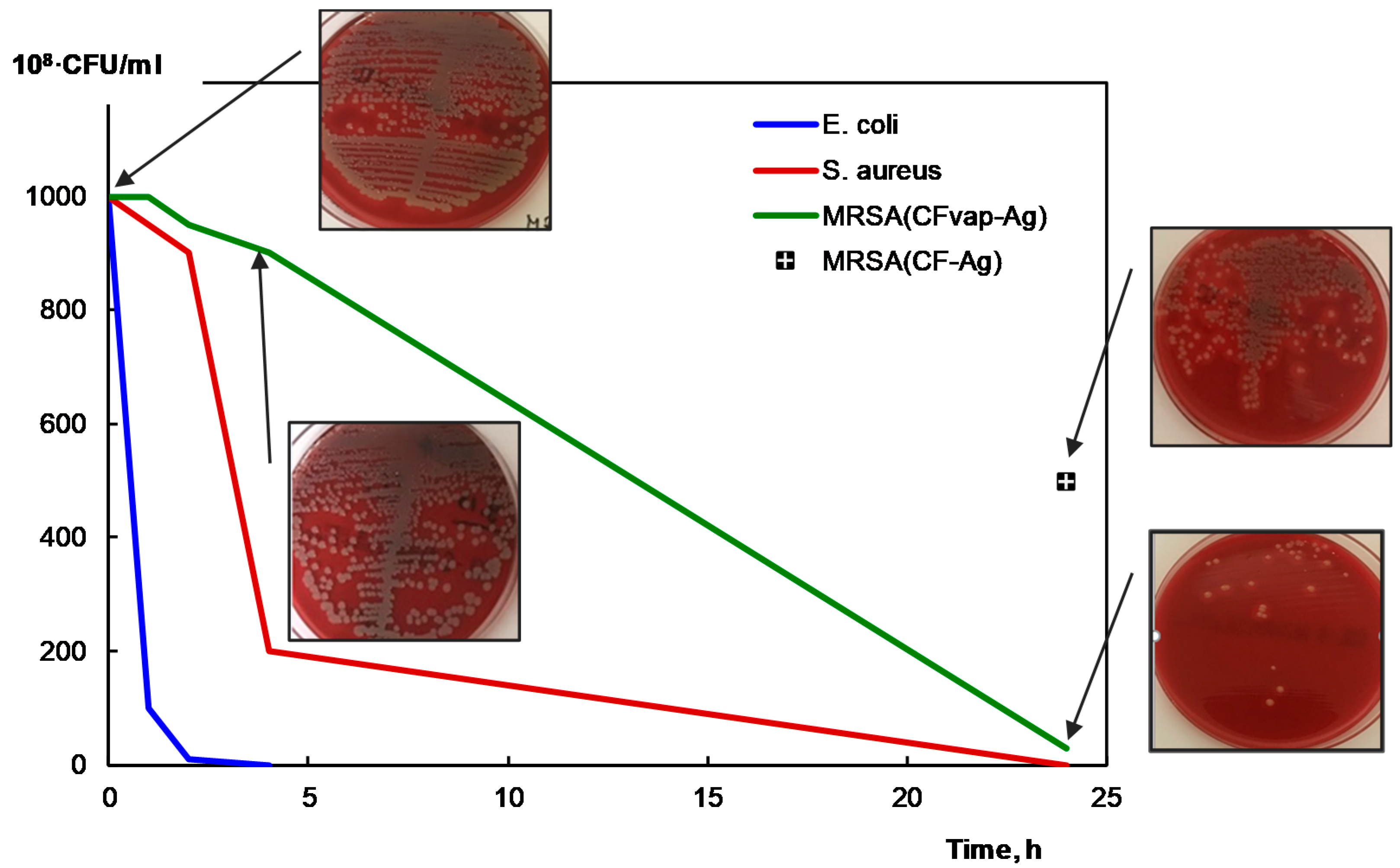
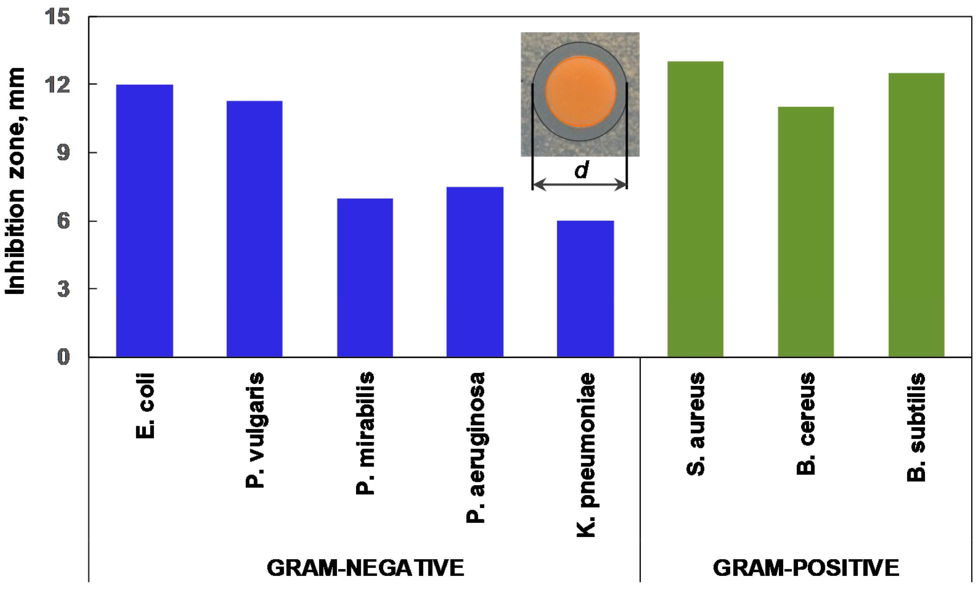
2.5. Antibacterial Activity Studies

The antimicrobial properties were evaluated against Gram-negative and Gram-positive bacteria strains. Two different antibacterial test methods were used.
For CF powder specimens, the antibacterial activity was evaluated by the agar dilution test. Bacterial strains were cultivated on 5% blood agar (BD, Avantor, Radnor, PA, USA) and incubated at the temperature of 35 °C for 20–24 h. CF powder (1 g) was placed in a 0.5 MF turbidity bacterial inoculum in sterile saline at the ratio of 1:9. The prepared suspension was well mixed by pipetting and incubated at 35 °C. After 1 h of incubation, it was spread on 5% blood agar plate with a sterile disposable 1 µL loop. The procedure was repeated after 2, 4, and 24 h of incubation. Blood agar was incubated at 35 °C for 24 h, and bacterial colony growth was evaluated.
The antibacterial activity of the PDMS composite film against the selected Gram-negative and Gram-positive pathogens was assessed by Kirby–Bauer disk diffusion susceptibility test method. The bacteria strains were spread on the Mueller–Hinton Agar (Merck, Gernsheim, Germany). PDMS composite discs (about 5 mm in diameter) were placed on agar plates and incubated at 37 °C for 24 h. The zone of inhibition was observed after 1, 2, 4, and 24 h of incubation.
The test microorganisms included Gram-negative strains, such as Escherichia coli ATCC 25922, Proteus vulgaris ATCC 29905, Proteus mirabilis ATCC 7002, Pseudomonas aeruginosa ATCC 27853, and Klebsiella pneumoniae ATCC 700603, and Gram-positive strains, such as Staphylococcus aureus ATCC 49775, Bacillus cereus ATCC 8035, Bacillus subtilis ATCC 6633, and methicillin-resistant Staphylococcus aureus (MRSA).

3. Results

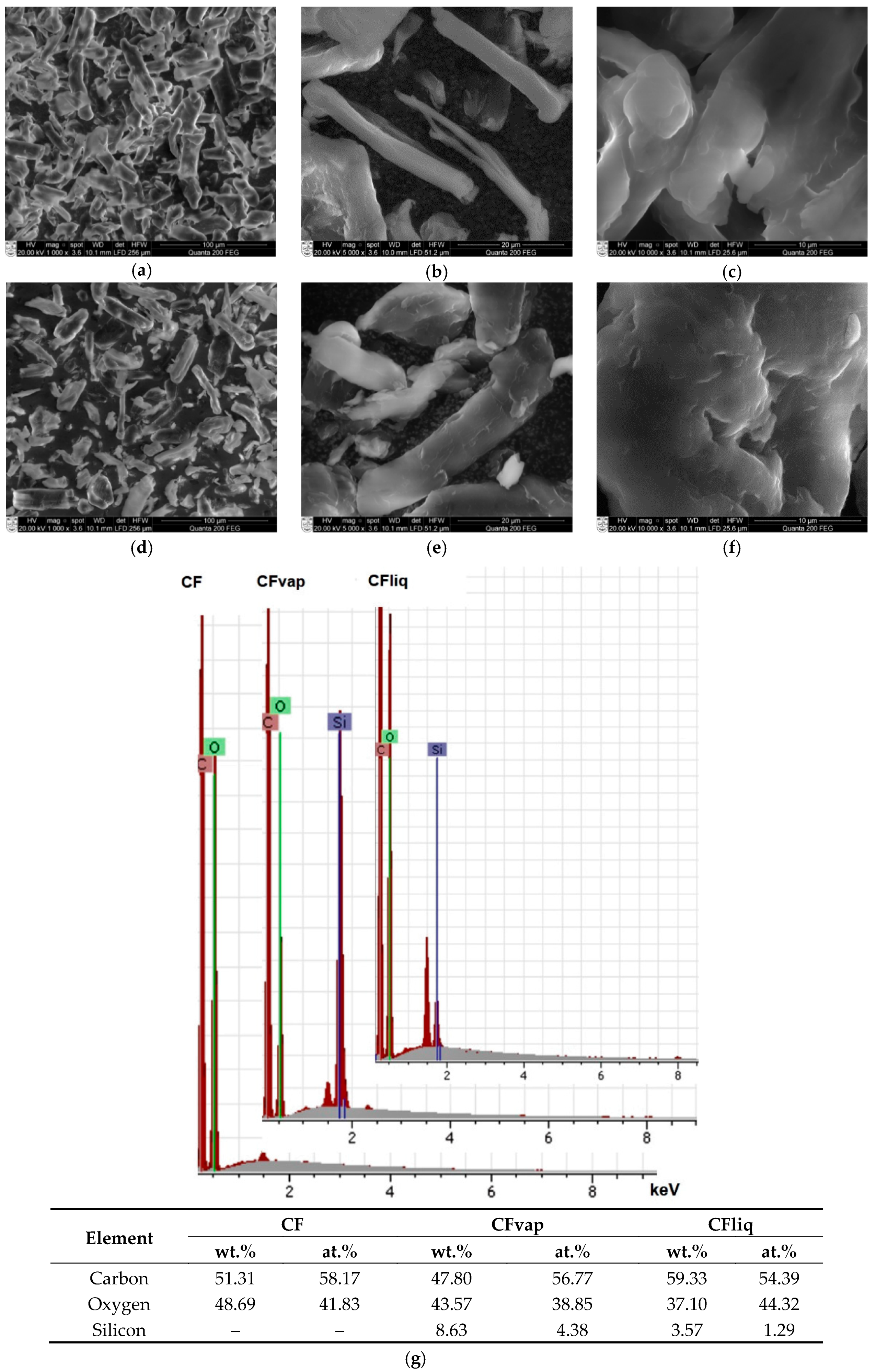
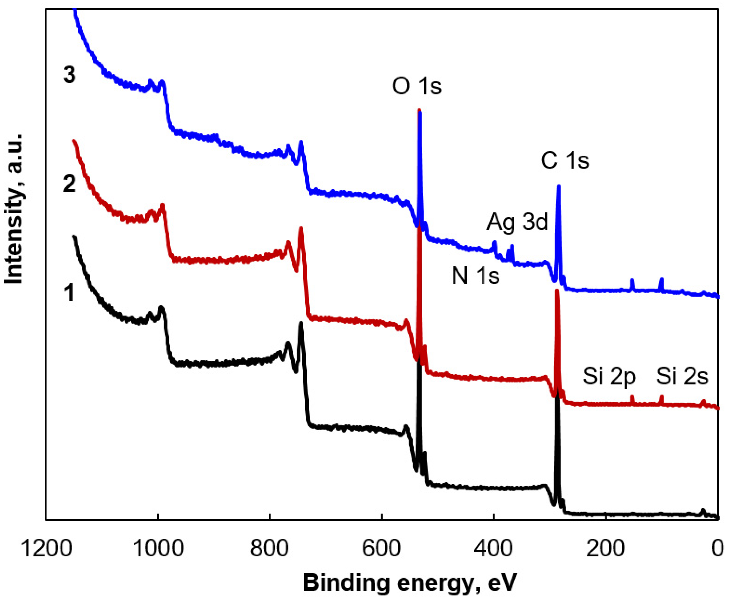
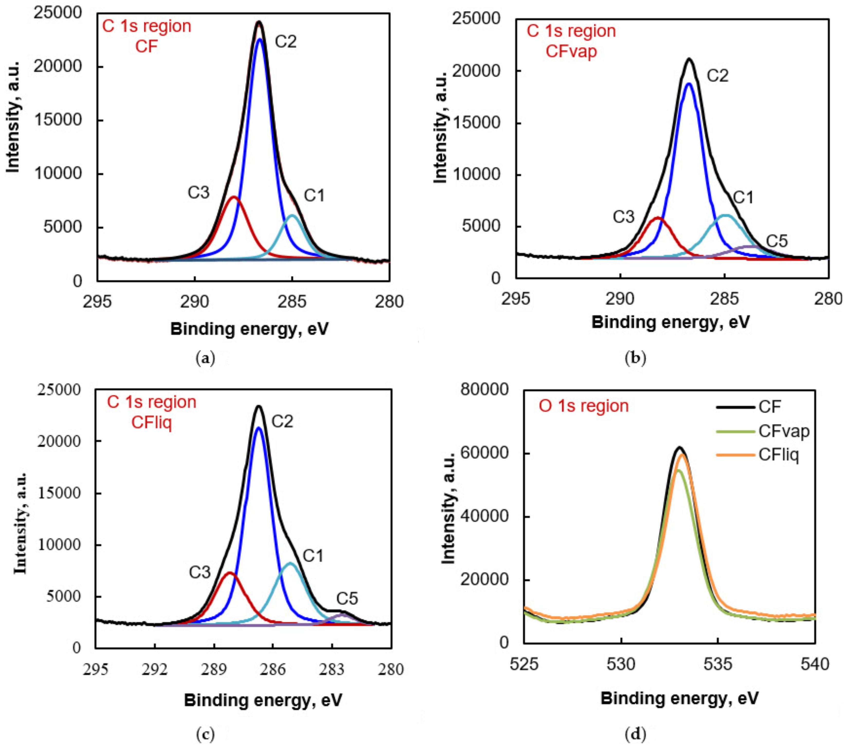
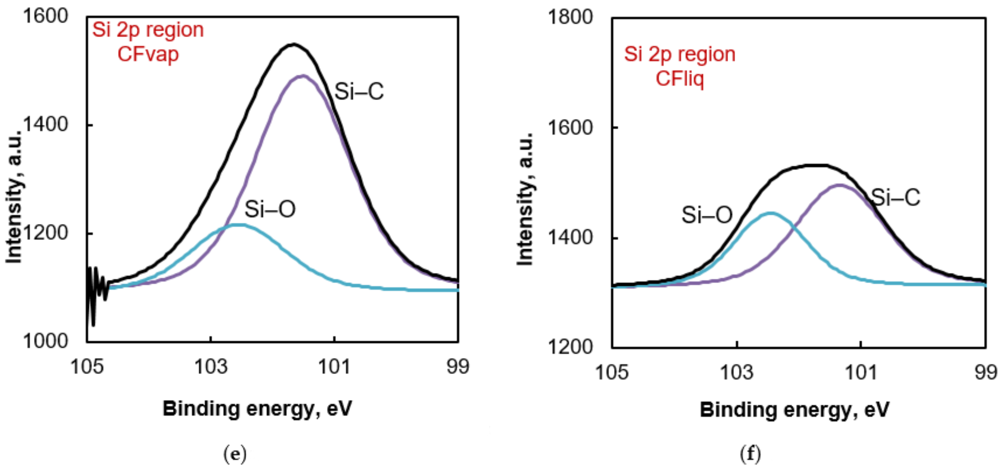
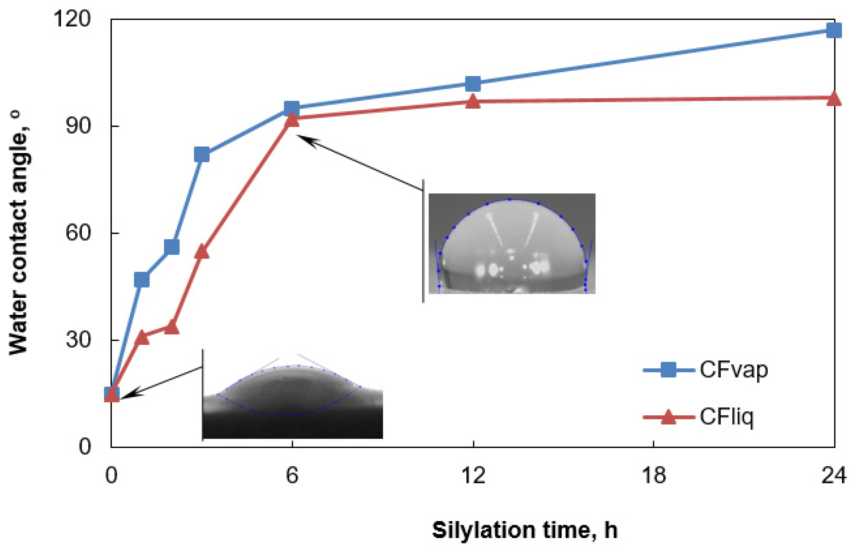
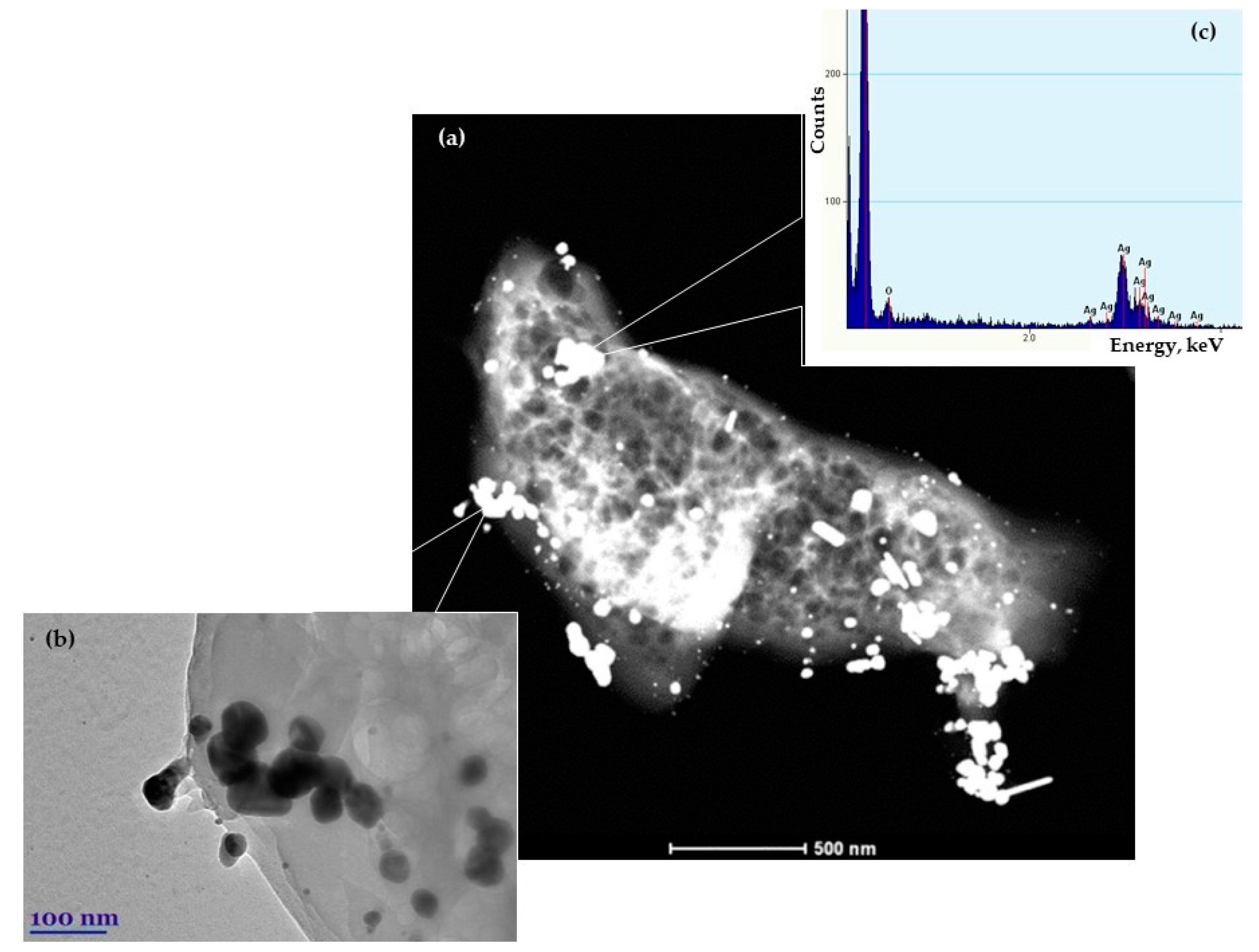
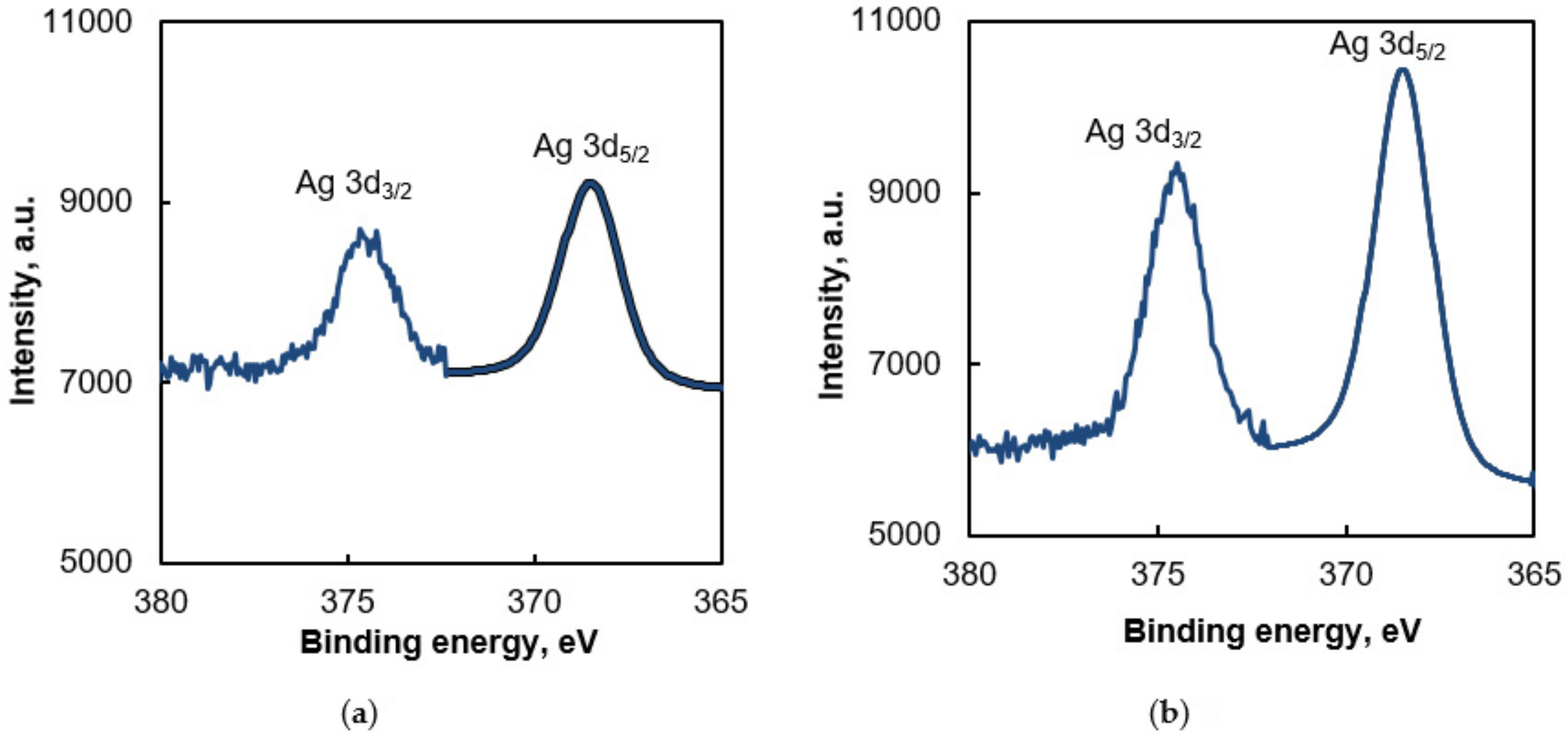
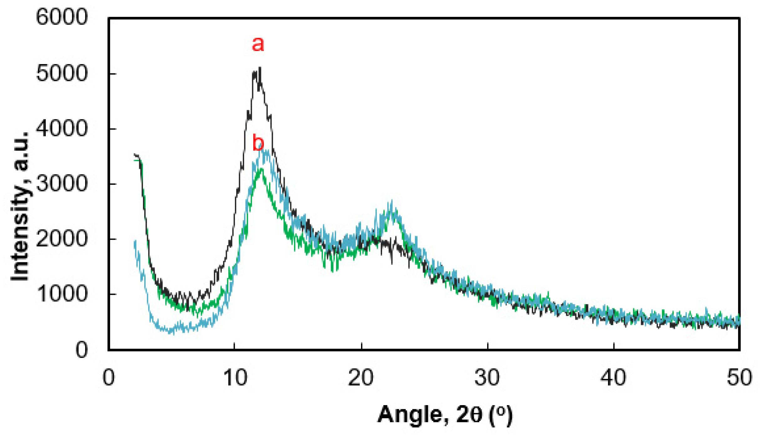
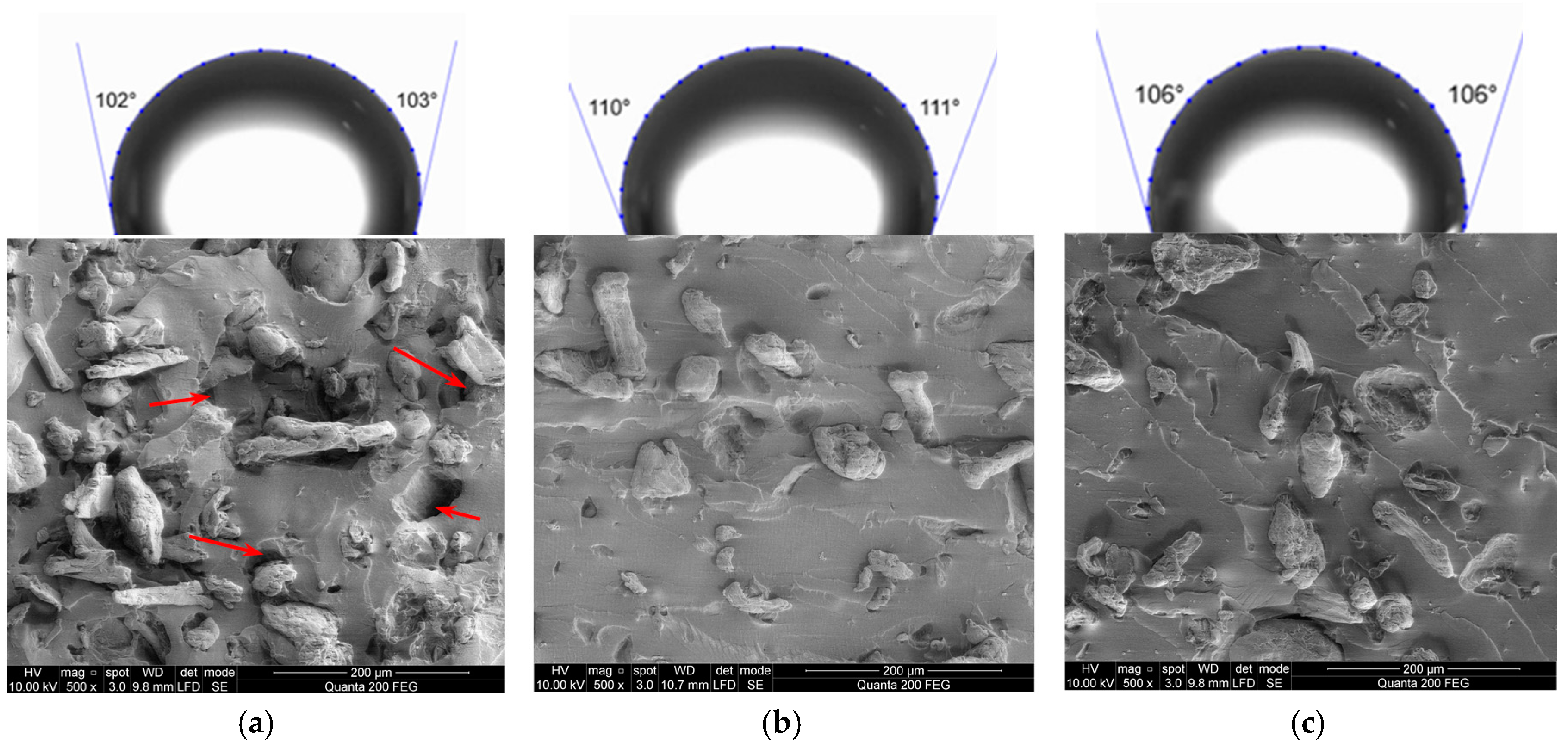
3.1. Morphology and Properties of Silylated CFs

The morphology of the microfibers to be used was investigated by SEM and TEM analysis. SEM images revealed the rod-like shape of untreated CFs (Figure 2a), which are composed of interconnected variable-size fibrils (Figure 2b,c). The compact agglomeration shows that cellulose chains have an intermolecular hydrogen bonding and a strong interaction between the cellulosic chains. As observed in Figure 2a, the size and shape of CFs is not uniform. Two CF shapes can be detected based on SEM analysis. The first one is like a rod with rounded ends on both sides, while the second shape is a rectangle that is assumed to be formed as a result of the breaking down of an amorphous region. Size distribution histograms revealed the main diameter of untreated CFs ranged from 10 to 20 μm, while length ranged from 35 to 50 μm (Figure 2d,e). The aspect ratio l/d of CF was found to be 2 to 7.
Cellulose is a semicrystalline material that has both crystalline and amorphous regions [52]. As can be seen from TEM images of CFs (Figure 3), morphology varies over the microfiber’s length. The regular structure is changed by fibrillated one, which consists of randomly entangled submicron fibrils. The fibrillated structure has a much higher surface area than regular cellulose microfibers.
FT-IR spectroscopy was used to analyze the CF samples treated with HMDS (Figure 4). The absorption bands of cellulose are observed in two wave number regions, namely the OH and CH stretching vibrations in the 3680–2700 cm−1 region and 1700–400 cm−1 region. This is attributed to stretching vibrations of different groups. The broad peak at 3350 cm−1 is characteristic for stretching vibration of the hydroxyl group OH, which also includes inter- and intramolecular hydrogen bond vibrations in cellulose [53]. The mixture of inter- and intramolecular hydrogen bonds is considered to cause the broadening of the OH band [54]. The CH stretching of asymmetric and symmetric methyl and methylene groups can be found in the region of 2990–2150 cm−1 [55]. The obtained data confirm that the structure of the investigated cellulose belongs to the Iβ crystalline type [56]. The peak located at 1644 cm−1 correspond to the vibration of water molecules absorbed in cellulose [56]. The bands at 1430, 1373, 1323, and 1275 cm−1 are assigned to CH2 symmetric bending, CH bending, and CH2 wagging vibration, respectively [54,55]. The bands observed at 1166, 1112, 1060, 1031, and 897 cm−1 are due to the asymmetric C–O–C bridge stretching, the anhydroglucose ring asymmetric stretching, C–O stretching, C–H in-plane deformation, and C–H deformation of cellulose, respectively [54,55]. The band at around 1430 cm−1 is associated with the amount of the crystalline structure of the cellulose, while the band at 897 cm−1 is assigned to the amorphous region in cellulose [57]. The intensity of peaks at the region of 3150–3560 cm−1 was found to be changed as a result of cellulose silylation [58]. Besides, the new absorption peaks observed at 1254 and 845 cm−1 are indicative of Si–C stretching vibration, indicating that chemical moieties with trimethylsilyl (–O–Si–(CH3)3) appear on the CF surface [23,59]. It is worth mentioning that the products of the silylation reaction are located in a very thin layer on the CF surface. Therefore, the amounts of these products are low and their detection by FT-IR is difficult.
Morphological comparison between untreated and HMDS-silylated microfibers, performed using SEM imaging, is shown in Figure 5. As can be seen from Figure 5a,d, CFvap and CFliq exhibit shape, dimensions, and polydispersity close to those of CFs. However, there are slight differences in silylated microfiber surface morphology. These microfibers were shown to have a smoother surface compared to the untreated ones, especially in the case of CFvap (Figure 5b,c).
The elemental composition of the microfiber surface was analyzed using SEM-EDX data. Typical EDX spectra and the elemental composition of the CF surface are given in Figure 5g. The elemental composition was determined by averaging at least three scanning spots. The comparison of spectra reveals the appearance of silicon (Si) after the silylation, indicating that the silane moieties have appeared on the CF surface. Moreover, the concentration of Si is near 3 times higher in the case of CFvap than in that of CFliq.
For further understanding of silylation mechanism, the XPS survey spectra of the untreated and silylated CFs were compared. It is evident from Figure 6a that the untreated CFs only show O 1s and C 1s peaks near 533 and 285 eV, respectively. In the spectrum of the surface-silylated CF, two additional peaks appeared near 150 and 100 eV, corresponding to Si 2s and Si 2p, respectively, and indicating the presence of silicon at the surface [60]. The oxygen/carbon (O/C) ratios for all investigated cellulose samples were also determined. For CFs, the contents of O and C are 44.78% and 54.49%, respectively, and the O/C ratio is 0.82. In contrast, the O/C ratios of silylated CFvap and CFliq show lower values—0.69 and 0.73, respectively. The decrease in the O/C ratio reflects the relative increase in carbon at the surface due to the substitution. The lowest value of O/C ratio in the case of CFvap indicates the higher degree of silylation.
The high-resolution scan of the C1s regions of the cellulose are deconvoluted into four peaks, namely C1, C2, C3, and C4, which provide the relative areas of the C–H/C–C at 285 eV (C1), C–O at 286.7 eV (C2), O–C–O or C=O at 288 eV (C3), and O–C=O at 289.8 eV (C4) moieties (Figure 7) [23]. The amount of C4 carbon was negligible; therefore, it was omitted. As can be seen from Figure 7b,c, the intensity of the C1 peak increases after silylation, while the intensity of C2 peak decreases compared to the spectrum of untreated CFs. This indicates the increase of C–C or C–H components and the decrease of hydroxyl groups in cellulose. Besides, a new peak ranging from 282.5 to 283.5 eV (C5) indicates the formation of Si–C bonds due to the silyl groups grafting on the CF surface [61]. As shown in Figure 7d, in the high-resolution spectrum for O1s, there is one broad peak positioned at 532.2 to 533.2 eV, which could be assigned to the presence of C–OH linkages [62,63]. A slight reduction of peak intensity after silylation indicates that a reaction takes place between the silane and the OH group on the cellulose surface.
The XPS scan results of Si 2p indicated that the CFvap and CFliq samples have two main peaks (Figure 7e,f). The first peak, ranging from 101.3 to 101.5 eV for both samples, represents Si–C bonding. The second peak, at 102.5 eV, is attributed to Si–O bonding [61]. In the case of CFvap, a larger area of Si–O means that a greater amount of silyl groups are grafted on the microfiber surface.
In order to compare the grafting efficiency of trimethylsiloxy groups the degree of surface substitution (the number of silyl groups per glucose unit, DSS) was calculated using the atomic concentrations of Si as determined by XPS [64]. The mass concentrations of Si were obtained as 7.2% and 2.9% for CFvap and CFliq, respectively. The calculated DSS values, 0.51 for CFvap and 0.18 for CFliq, indicate sufficient degrees of microfiber surface silylation. A higher value of DSS in the case of CFvap results in a more hydrophobic wetting behavior, which is confirmed by the data presented in Figure 8 which show the changes in water contact angle (WCA) as a function of treatment time. Water droplets were deposited on the compressed CF powder surface. The WCA on the untreated CF surface was obtained to be 15° ± 1°, which corresponds to the typical hydrophilic character of cellulose. The hydrophobicity of microfibers was improved drastically as the silylation time increased to 6 h. In this case, the WCA on the CFvap surface increased up to 95° ± 1°, while it increased to 92° ± 1° on that of the CFliq. A longer silylation reaction time resulted in a further increase of WCA values. At the treatment time of 24 h, the WCA values of CFvap and CFliq reached 117° ± 2° and 98° ± 1°, respectively. Thus, the vapor deposition technique provides a higher functionalization degree of the cellulose microfiber surface, resulting in a more hydrophobic wetting behavior.
The Ag nanoparticles (Ag NPs) can be generated on the CF surface to impart antibacterial properties. In this study Ag NPs were synthesized by in situ polyol reduction method in the presence of PVP. PVP was used not only as reducing agent, but also for preventing the Ag NPs from growing and agglomerating due to the steric effect [65]. After the introduction of PVP, Ag+ ions or Ag0 particles can interact with N or O in PVP, and covered layers are generated on the surface [66]. Besides, it was found [67] that cellulose may act as silver reduction agent through its hydroxyl groups, although the reducing power is low and effective only at high temperature. Ag NPs stabilized by PVP via electrostatic interactions are distributed on the silylated CF surface; the morphology of the resultant CF–Ag nanohybrid composite can be seen in Figure 9. It is evident that polydispersed Ag NPs, almost spherical in shape, are irregularly precipitated on the CF surface with some aggregation. There is a high variability in particle size, with sizes ranging from 9 to 46 nm. EDS analysis confirmed the presence of Ag NPs on CF surface—a strong Ag peak was detected at 3 keV, while signals from C and O, belonging to cellulose, were also recorded (Figure 9c). It should be mentioned that no visible differences between untreated and silylated CF–Ag nanohybrid morphologies were observed.
XPS spectral analysis was carried out to confirm the immobilization of Ag NPs on the CF surface. In the survey spectrum, additional peaks were depicted at 399 eV, corresponding to N1s (attributed to PVP), and at 367 eV, corresponding to Ag 3d (Figure 6, curve 3). Figure 10 shows the XPS spectra of the Ag 3d region of CF–Ag nanohybrid and CFvap–Ag nanohybrid samples. There are two peaks of Ag 3d5/2 and Ag 3d3/2 centered at binding energies of 368.5 and 374.5 eV, respectively, which prove that silver is present only in its metallic form, indicating the formation of Ag NPs on the surface of the microfibers [68]. The atomic concentration of Ag NPs is higher in the case of silylated CFvap compared to that of CF (1.52% and 1.27%, respectively). The mass concentrations of Ag were obtained as 9.41% for CF and 10.79% for CFvap.
Following the characterization of the CF–Ag nanohybrid, its antibacterial activity was assessed. Figure 11 shows the number of bacterial colonies grown on blood agar plates as a function of incubation duration with the tested nanohybrid when approximately 108 CFU (colony forming unit) were applied to the plates. It can be seen that the CFvap–Ag nanohybrid exhibited strong antimicrobial activity towards E. coli strains—no bacterial colonies were observed after 4 h incubation. Meanwhile, Gram-positive bacteria were more resistant to the nanohybrid. In the case of S. aureus, the number of CFUs was significantly reduced after 4 h of incubation, but bacteria colony growth was inhibited completely only after 24 h of incubation. Ag NPs caused a growth delay of MRSA bacteria viability. However, the presence of CF–Ag nanohybrid inhibited bacterial growth by 50% after 24 h of incubation, while at the same time the CFvap–Ag hybrid inhibited bacterial growth by more than 90%, probably due to possible interaction of the Ag NPs with silane [69].
The mechanism for bacterial growth inhibition observed for Ag NPs is not fully understood, but it is possible that it involves the interaction of Ag+ ions with biological macromolecules through protein thiol groups (–SH). Monovalent Ag+ ions replace H+ ions of sulfhydryl or thiol groups, inactivating the protein, decreasing membrane permeability, and finally causing cellular death [70]. The reaction of monovalent Ag with sulfhydryl groups produces much more stable S–Ag groups on the bacterial cell surface. Therefore, Ag+ ions may not permeate through cell membranes to react with the interior S–H groups and may be relatively nontoxic to humans and animals [71].

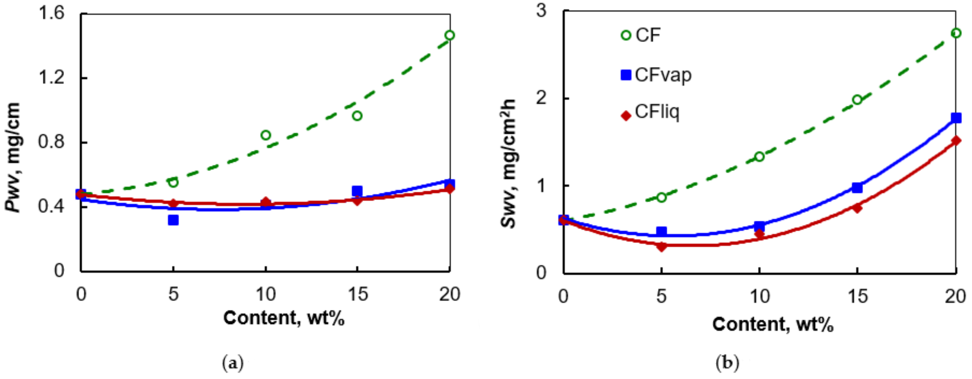
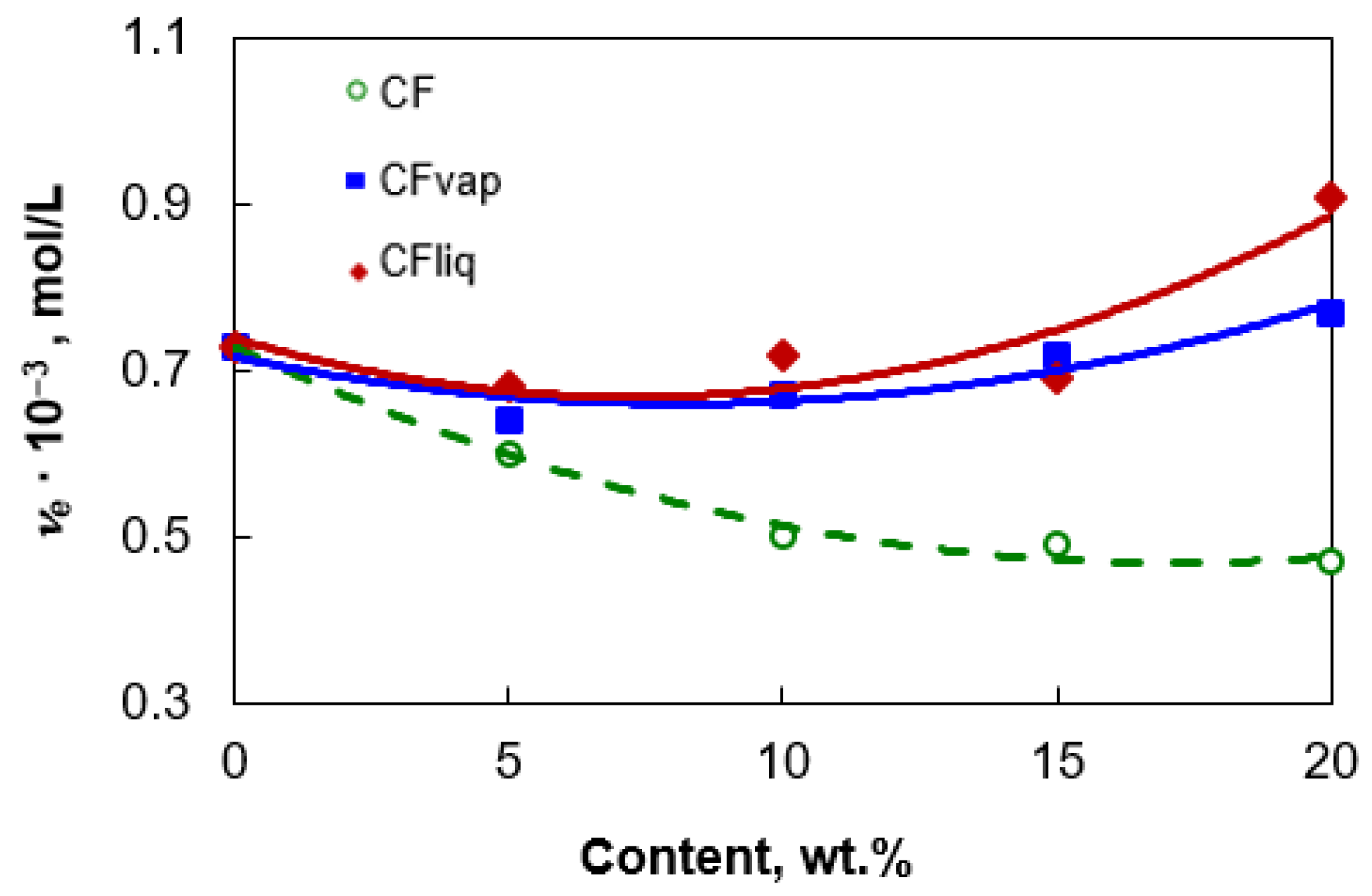
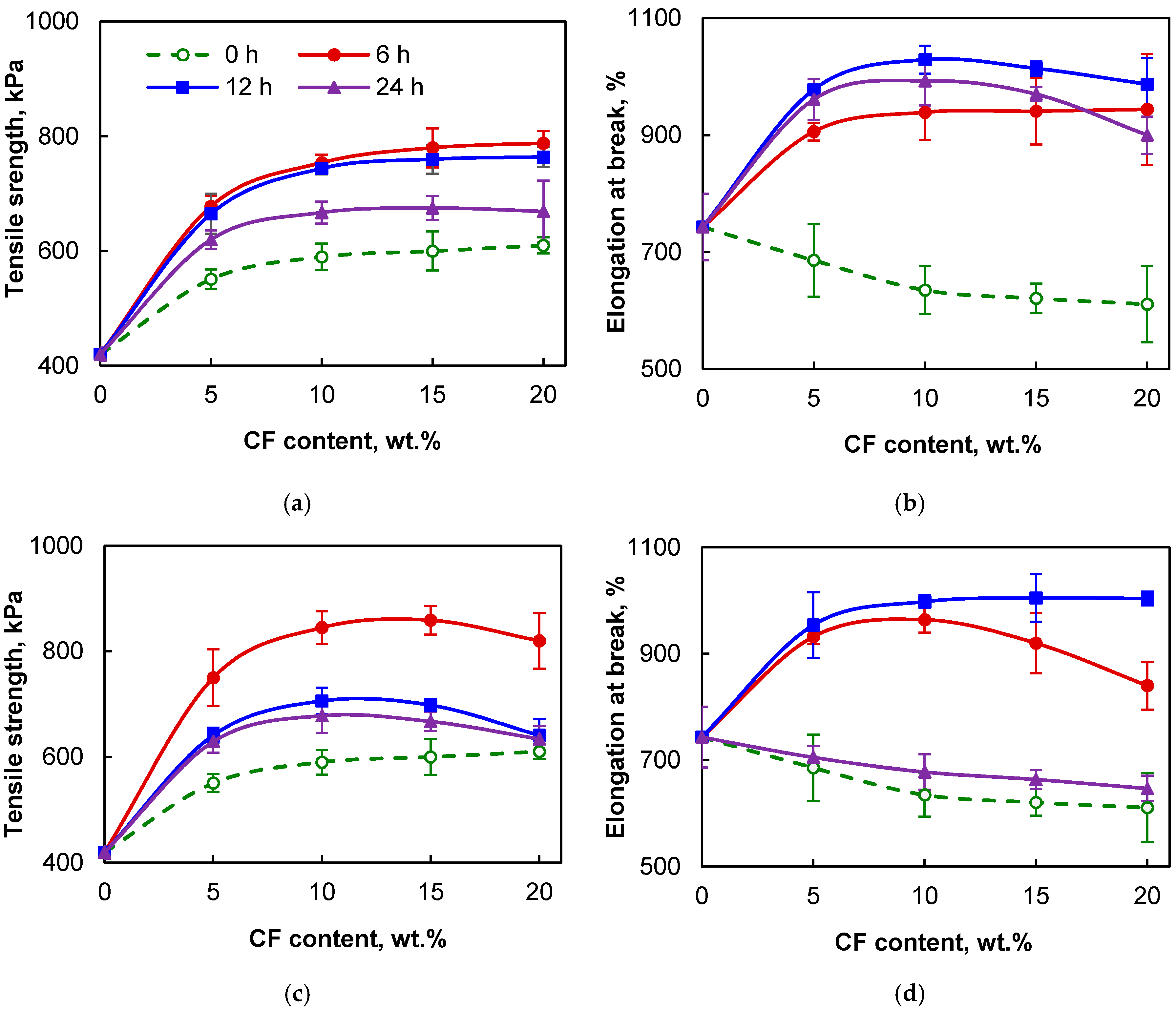
3.2. Structure and Properties of the PDMS/CF Composite

The properties of PDMS can be changed under loading of modified cellulose microfibers derivatives. Figure 12 shows the XRD pattern obtained for the PDMS composite samples with the 10 wt.% amount of CFs. The spectrum of PDMS shows a strong peak at around 11.7°, representing the amorphous region of the polymer. After loading the PDMS matrix with CF, additional diffraction peaks were be detected at 2θ values of 14.6°, 16.4°, 22.7°, and 34.8°, corresponding to the cellulose I crystallographic planes of (1 1 ¯ 0), (110), (200), and (004), respectively [25]. The intensive diffraction peak at 22.7°, resulting from CF, corresponds to the crystalline region in the PDMS composites. As can be seen, the grafting process of cellulose does not alter the crystalline structure, because silylation occurs essentially at the surface or in the amorphous regions of cellulose fibers [72].
SEM images of the fractured surfaces of tensile samples of PDMS/CF (10 wt.%) composites show that untreated microfibers are unevenly distributed in the PDMS matrix and tend to form aggregates due to their hydrophilic nature (Figure 13a). An increase in the filler amount would result in larger and more fragile filler aggregates. Besides, the clearly evident voids and withdrawal of CFs during rupture of the PDMS sample indicate poor wettability and low adhesion interaction between the cellulose particles and polymer matrix. Such defects may affect crack formation and later their propagation. In contrast, silylated CFvap and CFliq microfibers are more evenly distributed in the PDMS matrix, and no voids or other defects are visible in fractured surface (Figure 13b,c)). This can be attributed to the good adhesive interaction of the microfibers with the silicone matrix due to the surface silylation. A higher surface hydrophobicity decreases filler–filler interaction and prevents particle aggregation, leading to an increase of filler surface area and, thus, filler–polymer interaction [73]. As expected, the incorporation of silylated particles enhances the hydrophobic character of the PDMS surface (Figure 13). The loading of 10 wt.% of CFvap and CFliq increases the WCA values by 8% and 4%, respectively.
The influence of cellulose microfiber silylation on the water vapor behavior of PDMS/CF composite films is presented in Figure 14. Untreated CFs contain a large number of hydroxyl groups on their surfaces. Such highly hydrophilic filler strongly affects PDMS composite films’ water vapor permeability Pwv and water vapor sorption Swv properties: incorporation of up to 20 wt.% of CF leads to the increase of Pwv and Swv values by 3 and 4.5 times, respectively. Meanwhile, PDMS composites loaded with CFvap or CFliq show water vapor transfer behavior close to that of pure PDMS, even at high content of cellulosic filler, due to the decrease of void formation ability and increase of adhesion interaction at the interface with matrix, as was discussed earlier. Only some increase of composite sorption ability was noticed in the case of the highest content of silylated filler. The changes of water vapor behavior of PDMS/CF silylated composites show that functionalization of microfiber surfaces effectively prevents their direct contact with water vapor due to the hydrophobization, increase of the interaction between components, and crosslinking density of PDMS. Figure 15 illustrates the changes in crosslinking density νe of the PDMS network upon composition. For unfilled PDMS, crosslinking density was found to be 0.72 × 10⁻³ mol/L. Incorporation of untreated CF is accompanied with a noticeable decrease of crosslinking density of the PDMS network (down to 0.49 × 10⁻³ mol/L at 20 wt.% of filler), because microfibers may act as barriers to the formation of the crosslinking network [33]. Conversely, the crosslinking density of PDMS remains close to pure silicone when CFvap or CFliq are loaded. This suggests that the cellulose surface silylation reaction markedly increases interaction between PDMS/CF components. Besides, all the data reported above show that microfiber silylation technique, i.e., silylation by HMDS vapor deposition or by immersion in HMDS, has only a negligible effect on the permeability properties and crosslinking density of PDMS/CF composite.
The mechanical properties of PDMS/CF composites are dependent on the dispersion state of the filler within the matrix, elastically ineffective links, crosslinking density of the silicone network, and the filler–matrix interaction [25]. As can be seen from Figure 16, PDMS/CF composites’ elongation at break decreases, although tensile strength increases, with incorporation of untreated CFs due to a stiffening effect. Besides, as shown earlier (Figure 13), aggregated CFs may generate stress concentration and cause nonuniform stress transfer during tensile fracture of samples. This could be partly due to the poor adhesion between the fibers and the silicone matrix. However, surface silylation of cellulosic microfibers improves their dispersibility and imparts strong physical interaction at the interface with the PDMS matrix. Therefore, the addition of CFvap or CFliq significantly increases tensile strength and elongation at break of PDMS composites. More precisely, the addition of 10–15 wt.% of microfibers silylated for 6 h increases elongation at break by 1.3 times and tensile strength by about 2 times. Mechanical properties at tension slightly decrease for the samples with the highest content of filler and longest time of modification. At high loading, aggregation of even silylated microfibers into PDMS may occur, while a long time of modification can cause formation of chemical impurities on the microfiber surface. Therefore, it can be concluded that a significant increase in PDMS composites’ mechanical properties can be achieved at a filler loading of not higher than 15 wt.% and at the effective time (ca. 6 h) of CF surface treatment which improves the interfacial adhesion.
The PDMS composite loaded with the CF–Ag nanohybrid exhibits antibacterial activity against Gram-negative and Gram-positive bacteria strains (Figure 17). In this case, the antibacterial effect was evaluated by the size of the zones of inhibition around the disks.
Pure PDMS was used as control and no inhibition zone was observed, indicating that pure PDMS alone had no antibacterial properties. In the case of loading the CF–Ag nanohybrid into PDMS, Ag NPs begin to diffuse and inhibit the growth of both Gram-negative and Gram-positive bacteria. This is because Ag NPs can penetrate the bacterial cytoplasm and interact with cell components, causing damage and eventually death. By comparing the inhibition zones, wider inhibition diameters were observed for S. aureus, B. cereus, and B. subtilis strains. Some of the Gram-negative bacteria strains that were tested, such as P. mirabilis, P. aeruginosa, and K. pneumoniae, were only moderately sensitive to the PDMS/CF–Ag nanohybrid composite. This could be related to the cell wall structure of these bacteria.

4. Conclusions

A comparison of the vapor phase and liquid phase procedures for cellulose microfiber surface silylation with hexamethyldisilazane has been performed. Silylated microfibers show high dispersion and compatibility within a PDMS matrix and improve its mechanical properties without reducing the crosslinking density of PDMS chains. It was found that cellulose microfibers functionalized by the vapor phase of a silane coupling agent exhibit higher concentrations of trimethylsilyl groups on their surface, resulting in a more hydrophobic wetting behavior and a higher influence on the properties of PDMS. Silylation increases the antimicrobial activity of the cellulose microfiber–Ag nanohybrid obtained by in situ chemical reduction. This nanohybrid provides PDMS with the ability to inhibit the growth of both Gram-positive and Gram-negative bacteria.

Author Contributions

Conceptualization, V.J. and A.B.; Methodology, A.B. and V.J.; Validation, A.B., N.B., K.Ž., and R.A.; Formal Analysis, R.A.; Investigation, A.B. and N.B.; Resources, N.B.; Data Curation, R.A.; Writing-Original Draft Preparation, V.J. and K.Ž.; Writing-Review & Editing, V.J.; Visualization, V.J., A.B., and K.Ž.; Supervision, K.Ž.; Funding Acquisition, V.J.; Project Administration, V.J. All authors have read and agreed to the published version of the manuscript.

Funding

This research was funded by the European Social Fund and Republic of Lithuania, Grant No. 09.3.3-LMT-K-712-01-0074.

Acknowledgments

Support of the bilateral agreement between Bulgarian Academy of Sciences (IEMPAM) and Lithuanian Academy of Sciences (Kaunas University of Technology) is gratefully acknowledged.

Conflicts of Interest

The authors declare no conflict of interest.

References

  1. Ren, K.N.; Chen, Y.; Wu, H.K. New materials for microfluidics in biology. Curr. Opin. Biotechnol. 2014, 25, 78–85. [Google Scholar] [CrossRef]
  2. Gao, W.; Wang, X.; Xu, W. Magneto-mechanical properties of polydimethylsiloxane composites with a binary magnetic filler system. Polym. Composite 2019, 40, 337–345. [Google Scholar] [CrossRef] [Green Version]
  3. Kim, J.H.; Hwang, J.-Y.; Hwang, H.R. Simple and cost-effective method of highly conductive and elastic carbon nanotube/polydimethylsiloxane composite for wearable electronics. Sci. Rep. 2018, 8, 1375. [Google Scholar] [CrossRef] [PubMed] [Green Version]
  4. Curtis, J.; Colas, A. Medical applications of silicones. In Biomaterials Science: An Introduction to Materials in Medicine, 3rd ed.; Hoffman, B.D., Schoen, A.S., Lemons, F.J., Ratner, J.E., Eds.; Elsevier: Berlin, Germany, 2013; pp. 1106–1116. [Google Scholar]
  5. Kong, K.T.S.; Mariatti, M.; Rashid, A.A.; Busfield, J.J.C. Enhanced conductivity behavior of polydimethylsiloxane (PDMS) hybrid composites containing exfoliated graphite nanoplatelets and carbon nanotubes. Compos. B 2014, 58, 457–462. [Google Scholar] [CrossRef]
  6. Zhao, Y.; Zhang, Y.; Bai, S.; Yuan, X. Carbon fibre/graphene foam/polymer composites with enhanced mechanical and thermal properties. Compos. B Eng. 2016, 94, 102–108. [Google Scholar] [CrossRef]
  7. Smitha, A.; Rajeev, R.S.; Krishnaraj, K.; Sreenivas, N.; Manu, S.K.; Gouri, C.; Sekkar, V. Thermal protection characteristics of polydimethylsiloxane-organoclay nanocomposite. Polym. Degrad. Stab. 2017, 144, 281–291. [Google Scholar] [CrossRef]
  8. Alexandru, M.; Cazacu, M.; Vlad, S. Polydimethylsiloxane-silica composites. Influence of the silica on the morphology and the surface, thermal, mechanical properties. High Perform. Polym. 2009, 21, 379–392. [Google Scholar] [CrossRef]
  9. Gowda, Y.T.G.; Sanjay, M.R.; Bhat, K.S.; Madhu, P.; Senthamaraikannan, P.; Yogesha, B. Polymer matrix-natural fiber composites: An overview. Cogent. Eng. 2018, 5, 1446667. [Google Scholar]
  10. Istva, S.; Plackett, D. Microfibrillated cellulose and new nanocomposite materials: A review. Cellulose 2010, 17, 459–494. [Google Scholar]
  11. Panaitescu, D.M.; Frone, A.N.; Ghiurea, M.; Spataru, C.I.I.; Radovici, C.; Iorga, M.D. Properties of polymer composites with cellulose microfibrils. In Advances in Composite Materials—Ecodesign and Analysis; Attaf, B., Ed.; InTech: Nanterre, France, 2011; pp. 103–122. [Google Scholar]
  12. Palange, C.; Johns, M.A.; Scurr, D.J.; Phipps, J.S.; Eichhorn, S.J. The effect of the dispersion of microfibrillated cellulose on the mechanical properties of melt-compounded polypropylene–polyethylene copolymer. Cellulose 2019, 26, 9645–9659. [Google Scholar] [CrossRef] [Green Version]
  13. Jankauskaitė, V.; Abzalbekuly, B.; Lisauskaitė, A.; Procyčevas, I.; Fataraitė, E.; Vitkauskienė, A.; Janakhmetov, U. Silicone rubber and microcrystalline cellulose composites with antimicrobial properties. Mater. Sci. 2014, 20, 42–49. [Google Scholar] [CrossRef] [Green Version]
  14. He, M.; Lu, A.; Zhang, L. Advances in cellulose hydrophobicity improvement. In Food Additives and Packaging; ACS: Washington, WA, USA, 2014; pp. 241–274. [Google Scholar]
  15. Valášek, P.; Müller, M.; Šleger, V. Influence of plasma treatment on mechanical properties of cellulose-based fibres and their interfacial interaction in composite systems. Bioresources 2017, 12, 5449–5461. [Google Scholar] [CrossRef]
  16. Belgacem, M.; Gandini, A. The surface modification of cellulose fibers for use as reinforcing elements in composite materials. Compos. Interface 2005, 12, 41–75. [Google Scholar] [CrossRef]
  17. Yeo, J.S.; Hwang, S.H. Preparation and characteristics of polypropylene-graft-maleic anhydride anchored micro-fibriled cellulose: Its composites with polypropylene. J. Adhes. Sci. Technol. 2015, 29, 185–194. [Google Scholar] [CrossRef]
  18. Jeon, J.G.; Kim, H.C.H.; Kim, J.; Kang, T.J. Polystyrene nanocomposites reinforced with phenyl isocyanate-treated cellulose nanofibers. Funct. Compos. Struct. 2020, 2, 015002. [Google Scholar] [CrossRef]
  19. Jeun, J.-P.; Lee, Y.; Kang, P.-H.; Lee, D.D.-Y. Surface modification for the hydrophobization of cellulose nanocrystals using radiation-induced grafting. J. Nanosci. Nanotechnol. 2019, 19, 6303–6308. [Google Scholar] [CrossRef]
  20. Boujemaoui, A.; Sanchez, C.C.; Engström, J.; Bruce, C.; Fogelström, L.; Carlmark, A.; Malmström, E. Polycaprolactone nanocomposites reinforced with cellulose nanocrystals surface-modified via covalent grafting or physisorption: A comparative study. ACS Appl. Mater. Interfaces 2017, 9, 35305–35318. [Google Scholar] [CrossRef] [PubMed]
  21. Herrera-Franco, P.J.; Valadez-Gonzalez, A. A study of the mechanical properties of short natural-fiber reinforced composites. Compos. B 2005, 36, 597–608. [Google Scholar] [CrossRef]
  22. Abdelmouleh, M.; Boufi, S.; ben Salah, A.; Belgacem, M.N.; Gandini, A. Interaction of silane coupling agents with cellulose. Langmuir 2002, 18, 3203–3208. [Google Scholar] [CrossRef]
  23. Andresen, M.; Johansson, L.-S.; Tanem, B.S.; Stenius, P. Properties and characterization of hydrophobized microfibrillated cellulose. Cellulose 2006, 13, 665–677. [Google Scholar] [CrossRef]
  24. Gousse, C.; Chanzy, H.; Cerrada, M.L.; Fleury, E. Surface silylation of cellulose microfibrils: Preparation and rheological properties. Polymer 2004, 45, 1569–1575. [Google Scholar] [CrossRef]
  25. Yu, H.-Y.; Chen, R.; Chen, G.-Y.; Liu, L.; Yang, X.-G.; Yao, J.-M. Silylation of cellulose nanocrystals and their reinforcement of commercial silicone rubber. J. Nanopart Res. 2015, 17, 361. [Google Scholar] [CrossRef]
  26. Chinga-Carrasco, G.; Kuznetsova, N.; Garaeva, M.; Leirset, I.; Galiullina, G.; Kostochko, A.; Syverud, K. Bleached and unbleached MFC nanobarriers: Properties and hydrophobisation with hexamethyldisilazane. J. Nanopar. Res. 2012, 14, 1280. [Google Scholar] [CrossRef]
  27. Mormann, W. Silylation of cellulose with hexamethyldisilazane in ammonia—Activation, catalysis, mechanism, properties. Cellulose 2003, 10, 271–281. [Google Scholar] [CrossRef]
  28. Jankauskaitė, V.; Narmontas, P.; Lazauskas, A. Control of polydimethylsiloxane surface hydrophobicity by plasma polymerized hexamethyldisilazane deposition. Coatings 2019, 9, 36. [Google Scholar] [CrossRef] [Green Version]
  29. Grunert, M.; Winter, W. Nanocomposites of cellulose acetate butyrate reinforced with cellulose nanocrystals. J. Polym. Environ. 2002, 10, 27–30. [Google Scholar] [CrossRef]
  30. Zhang, Z.; Tingaut, P.; Rentsch, D.; Zimmermann, T.; Sèbe, G. Controlled silylation of nanofibrillated cellulose in water: Reinforcement of a model polydimethylsiloxane network. ChemSusChem 2015, 8, 2681–2690. [Google Scholar] [CrossRef]
  31. Soliveri, G.; Meroni, D.; Cappelletti, G.; Annunziata, R.; Aina, V.; Cerrato, G.; Ardizzone, S. Engineered organic/inorganic hybrids for superhydrophobic coatings by wet and vapour procedures. J. Mater. Sci. 2014, 49, 2734–2744. [Google Scholar] [CrossRef]
  32. Zhang, F.; Sautter, K.; Larsen, A.M.; Findley, D.A.; Davis, R.C.; Samha, H.; Linford, M.R. Chemical vapour deposition of three aminosilanes on silicon dioxide: Surface characterization, stability, effects of silane concentration, and cyanine dye adsorption. Langmuir 2010, 26, 14648–14654. [Google Scholar] [CrossRef]
  33. Deng, S.; Binauld, S.; Mangiante, G.; Frances, J.M.; Charlot, A.; Bernard, J.; Zhou, X.; Fleury, E. Microcrystalline cellulose as reinforcing agent in silicone elastomers. Carbohyd. Polym. 2016, 151, 899–906. [Google Scholar] [CrossRef]
  34. Jankauskaitė, V.; Lazauskas, A.; Griškonis, E.; Lisauskaitė, A.; Žukienė, K. UV-curable aliphatic silicone acrylate organic-inorganic hybrid coatings with antibacterial activity. Molecules 2017, 22, e964. [Google Scholar] [CrossRef] [Green Version]
  35. Kottmann, A.; Mejía, E.; Hémery, T.; Klein, J.; Kragl, U. Recent developments on the preparation of silicones with antimicrobial properties. Chem. Asian J. 2017, 12, 1168–1179. [Google Scholar] [CrossRef] [PubMed]
  36. Fang, L.; Chen, H. Mechanical and antibacterial properties of silicone rubber compounds filled with silver-zirconium phosphate modified by aluminate coupling agent. Polym. Plast. Technol. 2017, 56, 1969–1976. [Google Scholar] [CrossRef]
  37. Singh, R.; Shedbalkar, U.U.; Wadhwani, S.A.; Chopade, B.A. Bacteriagenic silver nanoparticles: Synthesis, mechanism, and applications. Appl. Microbiol. Biotechnol. 2015, 99, 4579–4593. [Google Scholar] [CrossRef]
  38. Durán, N.; Durán, M.; de Jesus, M.B.; Seabra, A.B.; Fávaro, W.J.; Nakazato, G. Silver nanoparticles: A new view on mechanistic aspects on antimicrobial activity. Nanomed. Nanotechnol. 2016, 12, 789–799. [Google Scholar] [CrossRef] [PubMed]
  39. Greulich, C.; Braun, D.; Peetsch, A.; Diendorf, J.; Siebers, B.; Epple, M.; Köller, M. The toxic effect of silver ions and silver nanoparticles towards bacteria and human cells occurs in the same concentration range. RSC Adv. 2012, 2, 6981–6987. [Google Scholar] [CrossRef]
  40. Ferdous, Z.; Nemmar, A. Health Impact of Silver Nanoparticles: A review of the biodistribution and toxicity following various routes of exposure. Int. J. Mol. Sci. 2020, 21, 2375. [Google Scholar] [CrossRef] [Green Version]
  41. Groza, A.; Ciobanu, C.S.; Popa, C.L.; Iconaru, S.L.; Chapon, P.; Luculescu, C.; Predoi, D. Tructural properties and antifungal activity against candida albicans biofilm of different composite layers based on Ag/Zn doped hydroxyapatite-polydimethylsiloxanes. Polymers 2016, 8, 131. [Google Scholar] [CrossRef] [Green Version]
  42. de Moraes, A.C.M.; Lima, B.A.; de Faria, A.F.; Brocchi, M.; Alves, O.L. Graphene oxide-silver nanocomposite as a promising biocidal agent against methicillin-resistant Staphylococcus aureus. Int. J. Nanomed. 2015, 10, 6847–6861. [Google Scholar] [CrossRef] [Green Version]
  43. Xu, Y.; Li, S.; Yue, X.; Lu, W. Review of silver nanoparticles (AgNPs)-cellulose antibacterial composites. Bioresources 2018, 13, 2150–2170. [Google Scholar] [CrossRef]
  44. Dong, Y.-Y.; Fu, L.-H.; Liu, S.; Ma, M.-G.; Wang, B. Silver-reinforced cellulose hybrids with enhanced antibacterial activity: Synthesis, characterization, and mechanism. RSC Adv. 2015, 5, 97359–97366. [Google Scholar] [CrossRef]
  45. Chen, G.; Yan, L.; Wan, X.; Zhang, Q.; Wang, Q. In situ synthesis of silver nanoparticles on cellulose fibers using D-glucuronic acid and its antibacterial application. Materials 2019, 12, 3101. [Google Scholar] [CrossRef] [Green Version]
  46. Bronstein, L.M.; Shifrina, S.B. Dendrimers as encapsulating, stabilizing, or directing agents for inorganic nanoparticles. Chem. Rev. 2011, 111, 5301–5344. [Google Scholar] [CrossRef] [PubMed]
  47. Balčiūnaitienė, A. Development and Investigation of Antimicrobial Polydimethylsiloxane Composites. Ph.D. Thesis, Kaunas University of Technology, Kaunas, Lithuania, 14 February 2019. [Google Scholar]
  48. Visakh, P.M.; Thomas, S. Preparation of bionanomaterials and their polymer nanocomposites from waste and biomass. Waste Biomass Valorization 2010, 1, 121–134. [Google Scholar] [CrossRef]
  49. Fu, P.F.; Glover, S.; King, R.K.; Lee, C.I.; Pretzer, M.R.; Tomalia, M.K. Polypropylene–polysiloxane block copolymers via hydrosilylation of monovinylidene capped isotactic polypropylene. ACS Polym. Prepr. 2003, 44, 1014–1015. [Google Scholar]
  50. Stalder, A.; Kulik, G.; Sage, D.; Barbieri, L.; Hoffmann, P. A snake-based approach to accurate determination of both contact points and contact angles. Colloid Surf. A 2006, 286, 92–103. [Google Scholar] [CrossRef] [Green Version]
  51. Flory, P.J.; Rehner, J.J. Statistical mechanics of crosslinked polymer networks I. Rubber-like elasticity. J. Chem. Phys. 1943, 11, 512–520. [Google Scholar] [CrossRef]
  52. Poletto, M.; Pistor, V.; Zattera, A.J. Structural characteristics and thermal properties of native cellulose. In Cellulose—Fundamental Aspects; IntechOpen: London, UK, 2013; pp. 45–68. [Google Scholar]
  53. Hospodarova, V.; Singovszka, E.; Stevulova, N. Characterization of cellulosic fibers by ftir spectroscopy for their further implementation to building materials. Am. J. Anal. Chem. 2018, 9, 303–310. [Google Scholar] [CrossRef] [Green Version]
  54. Popescua, M.C.; Popescua, C.-M.; Lisab, G.; Sakatac, Y. Evaluation of morphological and chemical aspects of different wood species by spectroscopy and thermal methods. J. Mol. Struct. 2011, 988, 65–72. [Google Scholar] [CrossRef]
  55. Jankowska, I.; Ławniczak, P.; Pogorzelec-Glaser, K.; Łapinski, A.; Pankiewicz, R.; Tritt-Goc, J. Cellulose microfibers surface treated with imidazole as new proton conductors. J. Mater. Chem. Phys. 2020, 239, 122056. [Google Scholar] [CrossRef]
  56. Carrilo, F.; Colom, X.; Sunol, J.J.; Saurina, J. Structural FTIR analysis and thermal characterization of lyocell and viscose-type fibres. Eur. Polym. J. 2004, 40, 2229–2234. [Google Scholar] [CrossRef]
  57. Åkerholm, M.; Hinterstoisser, B.; Salmén, L. Characterization of the crystalline structure of cellulose using static and dynamic FT-IR spectroscopy. Carbohydr. Res. 2004, 339, 569–578. [Google Scholar] [CrossRef]
  58. Xie, B.; Muscat, A.J. Silylation of porous methylsilsesquioxane film in suoercritical carbon dioxide. Microelect. Eng. 2004, 76, 52–59. [Google Scholar] [CrossRef]
  59. Che, M.-L.; Teng, J.-Y.; Lai, P.-C.; Leu, J. Moisture uptake and dielectric property of methylsilsesquioxane/high-temperature porogen hybrids and porous low-k films. J. Mater. Res. 2011, 26, 2987–2995. [Google Scholar] [CrossRef] [Green Version]
  60. Souguir, Z.; Dupont, A.-L.; Fatyeyeva, K.; Mortha, G.; Cheradame, H.; Ipert, S.; Lavédrine, B. Strengthening of degraded cellulosic material using a diamine alkylalkoxysilane. RSC Adv. 2012, 2, 7470–7478. [Google Scholar] [CrossRef]
  61. Kim, H.; Youn, J.R.; Song, Y.S. Eco-friendly flame retardant nanocrystalline cellulose prepared via silylation. Nanotechnology 2018, 29, 455702. [Google Scholar] [CrossRef]
  62. Liu, L.; Xie, J.P.; Li, Y.J.; Zhang, Q.; Yao, J. Three-dimensional macroporous cellulose-based bioadsorbents for efficient removal of nickel ions from aqueous solution. Cellulose 2015, 23, 723–736. [Google Scholar] [CrossRef]
  63. Samana, N.; Johari, K.; Kongc, H.; Mohtar, S.S.; Hassana, O.; Ali, N.; Mat, H. Enhanced elemental mercury removal by facile sulfurization of agrowaste chars. Chem. Eng. Res. Des. 2019, 144, 198–208. [Google Scholar] [CrossRef]
  64. Frone, A.N.; Panaitescu, D.M.; Chiulan, I.; Nicolae, C.-A.; Casarica, A.; Nicolae, C.-A.; Trusca, R.; Damian, C.; Purcar, V.; Alexandrescu, E.; et al. Surface treatment of bacterial cellulose in mild, eco-friendly conditions. Coatings 2018, 8, 221. [Google Scholar] [CrossRef] [Green Version]
  65. Song, Y.-J.; Wang, M.; Zhang, X.-Y.; Wu, J.-Y.; Zhang, T. Investigation on the role of the molecular weight of polyvinyl pyrrolidone in the shape control of high-yield silver nanospheres and nanowires. Nanoscale Res. Lett. 2014, 9, 17. [Google Scholar] [CrossRef] [PubMed] [Green Version]
  66. Lozovskis, P.; Jankauskaitė, V.; Guobienė, A.; Kareivienė, V.; Vitkauskienė, A. Effect of graphene oxide and silver nanoparticles hybrid composite on P. aeruginosa strains with acquired resistance genes. Int. J. Nanomed. 2020, in press. [Google Scholar]
  67. Ferraria, A.M.; Boufi, S.; Battaglini, N.; Botelho do Rego, A.M.; ReiVilar, M. Hybrid systems of silver nanoparticles generated on cellulose surfaces. Langmuir 2010, 26, 1996–2001. [Google Scholar] [CrossRef] [PubMed]
  68. Han, S.W.; Kim, Y.; Kim, K. Dodecanethiol-derivatized Au/Ag bimetallic nanoparticles: TEM, UV/VIS, XPS, and FTIR analysis. J. Colloid. Interface Sci. 1998, 208, 272–278. [Google Scholar] [CrossRef] [PubMed]
  69. Ghazizadeh, A.; Haddadi, A.A.; Mahdavian, M. The effect of sol–gel surface modified silver nanoparticles on the protective properties of the epoxy coating. RSC Adv. 2016, 6, 18996–19006. [Google Scholar] [CrossRef]
  70. Barud, H.S.; Regiani, T.; Marques, R.F.C.; Lustri, W.R.; Messaddeq, Y.; Ribeiro, S.J. Antimicrobial bacterial cellulose-silver nanoparticles composite membranes. J. Nanomater. 2011, 2011, 721631. [Google Scholar] [CrossRef] [Green Version]
  71. Morones, J.R.; Elechiguerra, J.L.; Camacho, A.; Morones, J.R.; Elechiguerra, J.L.; Camacho, A.; Holt, K.; Kouri, J.B.; Ramírez, J.T.; Yacaman, M.J. The bactericidal effect of silver nanoparticles. Nanotechnology 2005, 16, 2346–2353. [Google Scholar] [CrossRef] [Green Version]
  72. Mangiante, G.; Alcouffe, P.; Burdin, B.; Gaborieau, M.; Zeno, E.; Petit-Conil, M.; Bernard, J.; Charlot, A.; Fleury, E. Green nondegrading approach to alkyne-functionalized cellulose fibers and biohybrids thereof: Synthesis and mapping of the derivatization. Biomacromolecules 2013, 14, 254–263. [Google Scholar] [CrossRef]
  73. Fröhlich, J.; Niedermeier, W.; Luginsland, H.-D. The effect of filler–filler and filler–elastomer interaction on rubber reinforcement. Compos. A Appl. Sci. Manuf. 2002, 36, 449–460. [Google Scholar] [CrossRef]
Figure 1. Silylation setups showing the treatment of cellulose microfiber surfaces with HMDS by (a) chemical vapor deposition and (b) modification from the liquid phase. (c) The scheme of cellulose silylation with HMDS.
Coatings 10 00567 g001
Figure 2. (ac) SEM images of CFs at different magnifications; (d) Diameter distribution histogram. (e) Length distribution histogram.
Coatings 10 00567 g002
Figure 3. TEM images of CF: (a) Microfiber; (b) Fibrillated structures; (c) Microfiber with different morphology.
Coatings 10 00567 g003
Figure 4. FTIR spectra of (a) CF, (b) CFliq, and (c) CFvap.
Coatings 10 00567 g004
Figure 5. SEM images at different magnifications of (ac) CFvap and (df) CFliq. (g) SEM-EDS data of all cellulose samples.
Coatings 10 00567 g005
Figure 6. XPS low-resolution survey spectra of untreated CF (curve 1), silylated CF (curve 2), and silylated CF–Ag nanohybrid (curve 3).
Coatings 10 00567 g006
Figure 7. High-resolution XPS spectra for the untreated and silylated CFs: (ac) C 1s peak; (d) O 1s peak; (e,f) Si 2p peak.
Coatings 10 00567 g007aCoatings 10 00567 g007b
Figure 8. Effect of silylation time and technique on the water contact angle of CF powders.
Coatings 10 00567 g008
Figure 9. CF–Ag nanohybrid: (a) TEM image; (b) STEM image; (c) EDS spectrum.
Coatings 10 00567 g009
Figure 10. High-resolution XPS spectra of the Ag 3d peak: (a) CF–Ag NP hybrid; (b) CFvap–Ag nanohybrid.
Coatings 10 00567 g010
Figure 11. Number of bacteria colonies as a function of the incubation time with CFvap–Ag nanohybrid on agar plates (p < 0.01; n = 4). The photographs inserted show plates initially supplemented with 108 CFU/mL of MRSA and incubated with CF–Ag and CFvap–Ag nanohybrids for different periods.
Coatings 10 00567 g011
Figure 12. X-ray diffractograms: (a) PDMS, (b) PDMS composite with 10 wt.% of CF; (c) and PDMS composite with 10 wt.% of CFvap.
Coatings 10 00567 g012
Figure 13. SEM images of fractured surfaces of tensile samples of PDMS/CF (10 wt.%) composites and water droplets on their surface at the loading of (a) CF, (b) CFvap, and (c) CFliq (silylation time 6 h).
Coatings 10 00567 g013
Figure 14. Dependence of PDMS/CF composite films’ water vapor permeability Pvw (a) and water vapor sorption Swv (b) upon CF content and treatment mode (treatment duration 6 h).
Coatings 10 00567 g014
Figure 15. Dependence of PDMS crosslinking density νe upon CF content and treatment mode (treatment duration 6 h).
Coatings 10 00567 g015
Figure 16. Dependence of PDMS/CF composites’ tensile strength (a,c) and elongation at break (b,d) upon CF content, treatment time and mode: (a,b) CFvap; (c,d) CFliq.
Coatings 10 00567 g016
Figure 17. The diameter of the zone of inhibition produced by PDMS/CF–Ag (10 wt.%) composite against Gram-negative and Gram-positive bacteria strains.
Coatings 10 00567 g017

