Article

Influence of Laser Energy Density on Interfacial Diffusion Bonding and Surface Density of Chromium Coating by Multi-Arc Ion Plating on Zirconium Alloy

1
School of Resources, Environment and Safety Engineering, University of South China, Hengyang 421001, China
2
School of Mechanical Engineering, University of South China, Hengyang 421001, China
3
State Power Investment Corporation Central Research Institute, Beijing 102209, China
*
Author to whom correspondence should be addressed.
Coatings 2020, 10(6), 565; https://doi.org/10.3390/coatings10060565
Submission received: 4 May 2020 / Revised: 3 June 2020 / Accepted: 9 June 2020 / Published: 15 June 2020

Abstract

:
The chromium coating prepared by multi-arc ion plating on the surface of zirconium alloy is easy to fall off under extremely harsh conditions due to the defects of larger particles, pores and weak adhesion between the coating and the zirconium alloy substrate. Here we apply a new composite process for the fabrication of Cr coating by laser melting multi-arc ion plating technology. The numerical model of temperature field laser melting treatment was established, and based on the analysis of the above temperature field of laser melting treatment, the laser with an energy density of 9 × 10⁴ J/cm2–18 × 104 J/cm2 was selected as the heat source. Laser energy density has a great influence on the diffusion behavior of Cr at the coating-substrate interface. When the energy density of laser is 9 × 10⁴ J/cm2, the laser heat source cannot provide enough energy to melt the surface of the coating, however, the Cr element diffuses slightly at the membrane base interface, forming a Cr diffusion zone of about 4 μm. When the energy density of the laser increases to 13.5 × 10⁴ J/cm2, the Zr element of the substrate diffused to the whole Cr coating, and the original Cr coating disappeared, forming a Zr-Cr diffusion and fusion zone of 30 μm. As the laser preparation process of the coating is a mixed sintering process of liquid phase sintering and solid phase sintering, the coating surface forms a dense zone and a loose zone respectively, resulting in the increase of porosity and particle rate. With the laser energy density increasing gradually, the Zr-Cr fusion zone is formed, and the coating surface particles were gradually refined and the pores were significantly reduced. With the further increase of laser energy density of 18 × 104 J/cm2, the Zr-Cr fusion zone was extended to 60 μm, and the porosity and particle rate were reduced to 0.3% and 0.4% respectively. In addition, the original stratification cracking of the film base at the fracture of the tensile specimen disappears, and the protrusion of the interface is formed. Coatings with dimple fractures were found, which indicates that the coating exhibited ductility and interfacial metallurgical bonding.

1. Introduction

Zirconium is widely used in nuclear fuel cladding tubes, and other important structural materials of nuclear reactors, including container tubes, positioning grids, end plugs and pressure tubes, due to its low neutron absorption cross section, good oxidation resistance, good processing and mechanical properties. Zirconium is known as the “first metal in the atomic age” [1,2]. When a water loss accident occurs in a nuclear reactor, the internal temperature of the reactor rises sharply, and the Zr alloy nuclear fuel cladding tube is prone to break due to oxidation in the process of strong quenching, leading to nuclear leakage. Meanwhile, zirconium alloy and water vapor are prone to a violent reaction at high temperature, releasing a lot of heat to accelerate the core melting, and producing a lot of hydrogen at the same time, making it easy to form a hydrogen explosion [3,4]. After the 2011 Fukushima nuclear accident in Japan, accident fault-tolerant fuel (ATF) has been one of the central themes in nuclear power engineering, and the materials of nuclear fuel cladding and its preparation process have become important research directions in relation to ATF [5,6,7,8,9,10,11,12]. The preparation of high antioxidant coatings on zirconium alloy is one of the effective methods to prevent the hydrogen evolution reaction between zirconium alloy and water at high temperature. However, candidate materials such as FeCrAl and Cr coatings are usually applied with the high thermal neutron absorption cross-section. For neutron economy, the thickness of the corrosion protection layer should be designed to be very thin, generally micron thickness.The thermal expansion coefficient of the coating material should not be different from that of the zirconium alloy because in the process of temperature change the combination of zirconium alloy and the coating will result in a difference of the thermal expansion coefficient of interface stress. Meanwhile, the coating preparation method should be able to provide a coating with high density, good bonding performance and accurate control of the thickness of the coating. Cr can be used as a protective coating on Zr alloy due to its excellent oxidation resistance and corrosion resistance, as its thermal expansion coefficient is similar to that of zirconium alloy [13,14,15,16]. Due to the advantages of rapid deposition rate, strong diffraction intensity, good surface quality and accurate control of coating thickness, multi-arc ion plating technology has a broad application prospect in the preparation of Zr alloy coating [17,18,19,20,21]. However, in the harsh environment of nuclear reactors, the coating prepared by multi-arc ion plating is physically bound to the Zr alloy substrate, which makes it easy to fall off when subjected to fatigue stress, thermal shock and intense irradiation. Therefore, the optimization of the preparation process to improve the surface density and the interface bonding is an important means to improve the safety of the coating on the Zr alloy surface [17,22,23,24]. Laser melting is a powerful method to eliminate defects of coating fabricated via multi-arc ion plating technology, but is only used to prepare coatings with the thickness of a millimeter scale, which cannot meet the strict requirement of thickness for coating zirconium alloy, thereby preventing it from widespread application for coating Zr alloy surfaces [25,26,27,28,29]. Here, we established the optimization model of laser power and used laser melting treatment technology to treat the Cr coating on the surface of Zr alloy prefabricated by multi-arc ion plating, which realized the precise control of the thickness of the coating in a micrometer scale, and improved the bonding performance via the transformation of metallurgical bonding of the substrate and coating [7]. In addition, we also investigated the diffusion behavior of Cr and Zr at the coating interface under different laser energy density conditions, in order to improve the safe service performance of Cr coating on the surface of nuclear fuel cladding tube Zr alloy under strong radiation environments.

2. Materials and Methods

2.1. Preparation of Cr Coating by Multi-Arc Ion Plating

Cr coating was prepared on the surface of Zr-4 alloy by TSU-650 magnetron sputtering machine. Chromium (purity of 99.99%) (Guonubao Titanium zirconium Industry Co., LTD., Baoji, China) was adopted as the target material with the sizes of Φ 100 mm × 18 mm. Specimens with the size of 20 mm × 20 mm × 5 mm were machined out of Zr-4 alloy as substrate ingot (1.2–1.7% Sn, 0.18–0.24% Fe, 0.07–0.13% Cr, Zr in balance, in wt %). After polishing, cleaning and drying pretreatment, the samples were settled in the vacuum chamber of the magnetron sputtering machine. The parameters of the preparation of the Cr coating with the thickness of 7 μm on surface the Zr-4 alloy by multi-arc ion plating are shown in Table 1.
The surface purity of the sample and the target material had a great influence on the bonding properties of the substrate and coating. The sample was first treated with alcohol and acetone under ultrasound, then the high negative bias pressure (−600 V) was used to stimulate Ar ions to bombard the target material and sample surface at high speed, so as to achieve the purpose of self-consuming cleaning.

2.2. Laser Melting Treatment of Multi-Arc Ion Plating Cr Coating

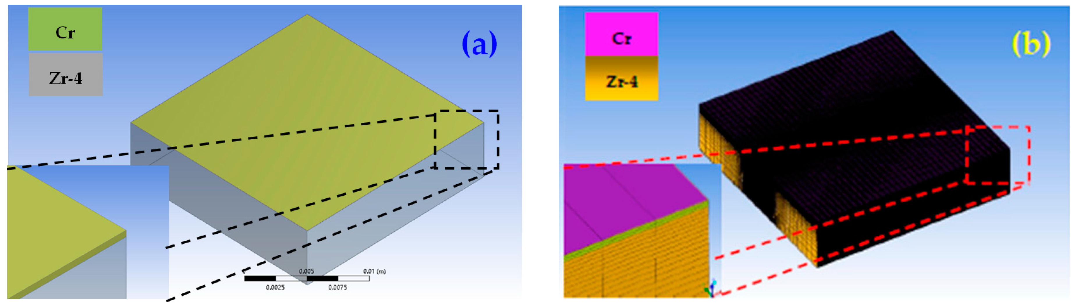
2.2.1. Laser Melting Treatment Temperature Field Model of Cr Coating

Under laser irradiation, the thermal stress generated by the large temperature gradient on the surface of the micrometer scale coating easily leads to cracks in the fusion layer [26]. Therefore, the selection of appropriate laser melting treatment process parameters is the key to the success of preparation of micrometer scale Cr coating with low crack density. We adopted the Gaussian distributed laser heat source model, loading the heat transfer boundary conditions and initial conditions based on the Fourier heat conduction equation [27,30], establishing the temperature field model of laser melting treatment, aiming to optimize the process parameters of the laser melting treatment.
(1). Laser beam heat source model
Gaussian distribution models are adopted as the laser heat source. We set the laser beam energy as constant, and established the Cartesian coordinate system as follows:
Q ( r ) = 2 A P π R 2 exp { 2 × [ ( x x 0 ) 2 + ( y y 0 ) ] 2 R 2 }
where, P is the input power of laser heat source, and A is the laser absorption rate of the sample’s surface; here we set it as 30%. R is the spot radius, since the laser beam is constantly moving, the coordinate of the center point of the spot O is set as ( x 0 , y 0 ), and x 0 and y 0 are the value of the spot center on the coordinate x-axis and y-axis, respectively.
(2). Initial and boundary conditions of laser melting treatment
(1)
Initial conditions: the initial temperature of the sample is set to room temperature 20 °C in the process of the laser melting treatment.
(2)
We applied the line heat source. The laser is loaded as the heat flux, which is the effective power density F of the sample surface, and their relationship is as follows:
F = A P / Ω
where, Ω is the laser irradiation area.
Due to the existence of the gaussian heat source, radiation heat transfer and air convection heat transfer on the sample surface during the process of laser melting, the boundary conditions are set as follows:
λ T Z = Q ( x , y , t ) + h ( T w T e )
where, λ is the heat conduction coefficient, Q is the surface heat flow function on the upper surface of the sample, h is the total heat transfer coefficient, T w is the surface temperature of the sample and T e is the environment temperature.
The heat transfer and radiation transfer are considered on all surfaces of the sample (except the upper surface), and the boundary conditions are set as follows:
λ T Z = h ( T w T e )
where, the total heat transfer coefficient h = h c + h r includes the convective heat transfer coefficient h c and the radiant heat transfer coefficient h r , of which the convective heat transfer coefficient is 10 W/(m2·°C), and the radiation heat transfer coefficient can be expressed as:
h r = σ ε ( T w 2 + T e 2 ) ( T w + T e )
σ is the Stefan–Boltzmann constant, which is 5.67 × 10⁻⁸. ε is the surface radiation coefficient of the sample, and is set as 70%.
(3). Numerical model of temperature field of laser melting treatment Cr coating
The thermally physical properties of the coating Cr and Zr-4 alloy are shown in Table 2. The relation between the specific heat capacity C p and temperature of the Zr-4 alloy is as follows:
C p = 230.925 + 0.638574 T 1.32646 × 10 3 T 2 + 1.016988 × 10 6 T 3   J / ( Kg · K )
The formula of the heat conduction coefficient of Zr-4 alloy is λ = a · C p · ρ , a is the heat diffusion coefficient, C p is the specific heat capacity and ρ is the density. Thus, the relation between λ and the temperature can be obtained as follows:
λ = 10.4777 + 2.77604 × 10 2 T 4.25308 × 10 5 T 2 + 2.30672 × 10 8 T 3 + 1.75853 × 10 11 T 4   W / ( m · K )
Using ANSYS software, the numerical model of the laser melting temperature field of Zr-4 alloy surface, Cr coating samples with the thickness of 7 μm were established, as shown in Figure 1, based on the laser melting process parameters as shown in Table 3. According to the overlap ratio of 40%, the overlap distance between the tracks was calculated, which was about 0.06 mm.

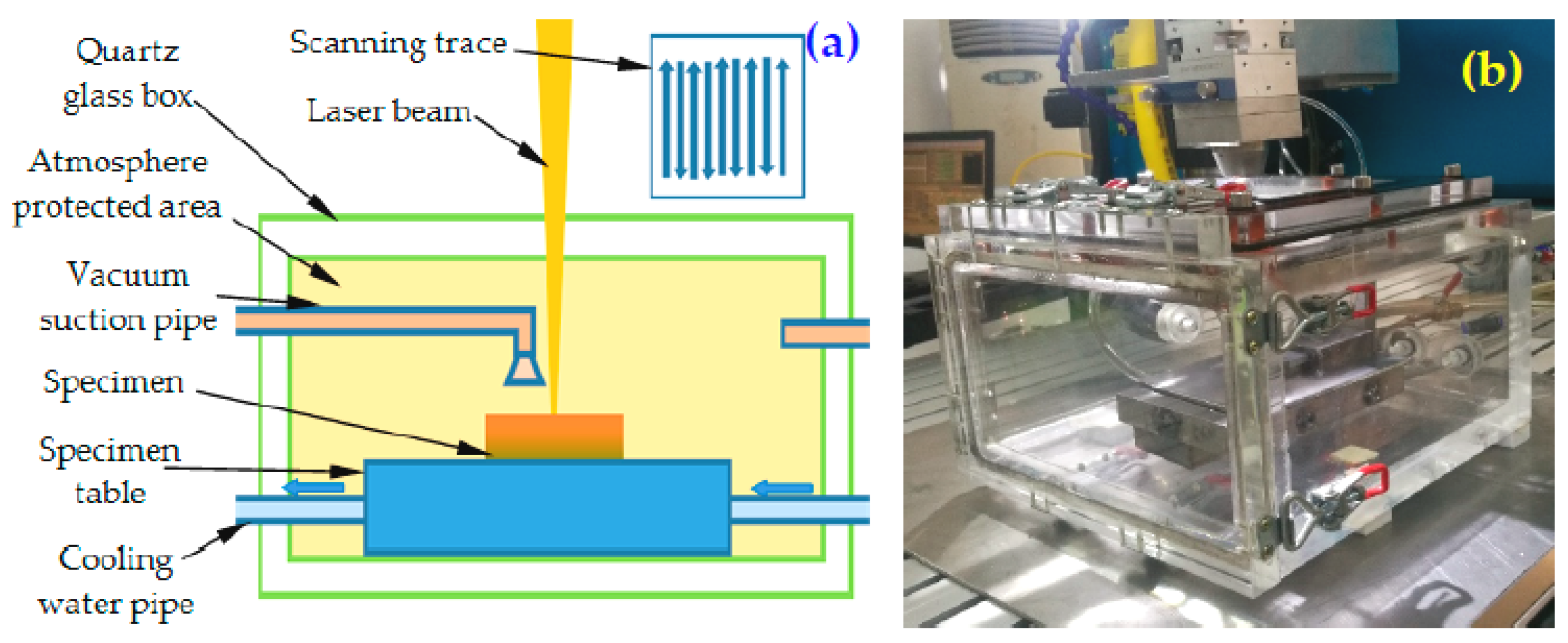
2.2.2. Laser Melting Treatment Test Apparatus

Argon is usually used as protective gas in the laser melting treatment process, however, the gas in the molten pool expands rapidly under the heat of laser irradiation, which makes the coating crack easily. Especially, cracking is more serious when the coating reaches micron level. In order to provide a vacuum environment for the process of coating laser melting treatment, a quartz glass atmosphere protection box is designed as Figure 2.

2.2.3. Laser Melting Treatment of Cr Coating Prepared by Multi-Arc Ion Plating

The laser scanning speed was 1600 mm/min, the spot diameter was 0.1 mm, and the laser power was 24, 30, 36, 42 and 48 W, respectively. The overlap spacing was 0.06 mm. The laser melting treatment test was conducted on samples No. 2–No. 6, while sample No. 1 is used as the contrast sample without the laser melting treatment.

2.3. Characterization and Analysis

Phases of the coating were identified by x-ray diffraction (XRD, xd-3). For the XRD, the X diffractometry with Cu Kα radiation operating at 45 keV and 200 mA was used. The tensile experiments were conducted by the universal material testing machine of WDW-20E under a speed of 0.2 mm/min at room temperature. The tensile fracture were observed using a scanning electron micrograph (SEM, QUANTA FEG 400, FEI) (American FEI Company, HI, USA) and the element distribution was analyzed by energy disperse spectroscopy (EDS, Oxford Instruments X-MaxN, Oxford, UK) equipped with SEM. The software of Image J (version 1.8.0.) was used to analyze the density of the coating.

3. Results and Discussion

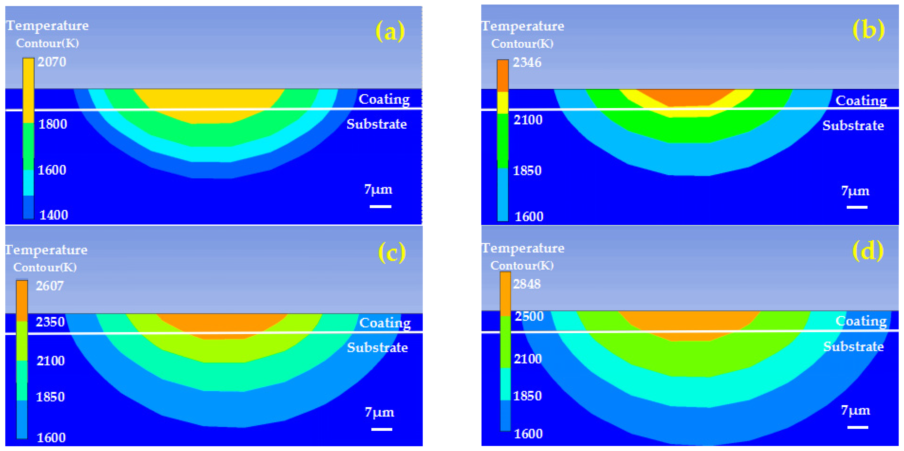
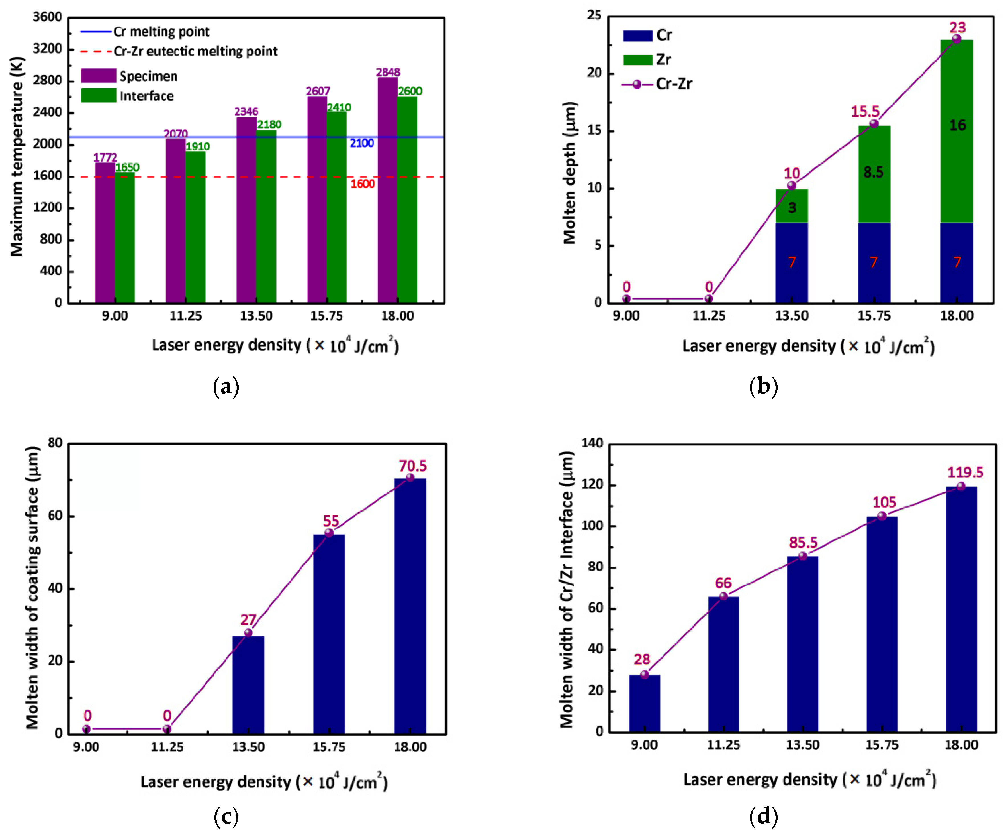
3.1. Temperature Field Simulation Analysis of Cr Coating Laser Melting Treatment

Figure 3 shows the temperature field distribution of each sample fabricated under different laser energy densities. With the increase of energy density, the heat-affected region of the sample can be enlarged. The specific relationship between laser energy density and the maximum temperature of the coating surface and Cr/Zr interface is shown in Figure 4a. In the temperature simulation cloud map, the Cr coating melting point (2130 K) and Zr melting point temperature (2100 K) were taken as the comparison objects, and the measured values of melting pool width and melting depth were calculated. The minimum melting point of Zr and Cr eutectic at the interface between the coating and substrate was taken as the comparison object, and the interfacial diffusion width was calculated. The relationship between the laser energy density and the melting pool width, depth, and the interfacial diffusion width are shown in Figure 4b–d, respectively. When the laser energy density is lower than 11.25 × 10⁴ J/cm2, the maximum temperature of the Cr coating is lower than its melting point, but the maximum temperature of the Cr-Zr interface is higher than the minimum melting point of Cr-Zr eutectic alloy (1600 K). When the laser energy density is higher than 13.5 × 10⁴ J/cm2, the maximum temperature of the Cr coating and Zr-4 alloy reach their melting point, the molten depth exceeds 10 μm, the molten width of Cr coating surface is greater than 27 μm, and the molten width of the Cr/Zr interface is more than 85.5 μm.
Based on the analysis of the above temperature field of the laser melting treatment, and investigating the diffusion behavior of the coating interface at different laser energy densities, we chose the laser energy density of 9 × 10⁴ J/cm2~18 × 104 J/cm2 as the technological parameters for the preparation of the Zr-4 alloy surface protection layer, which can make the Cr/Zr interface or Cr coating micro-melt.

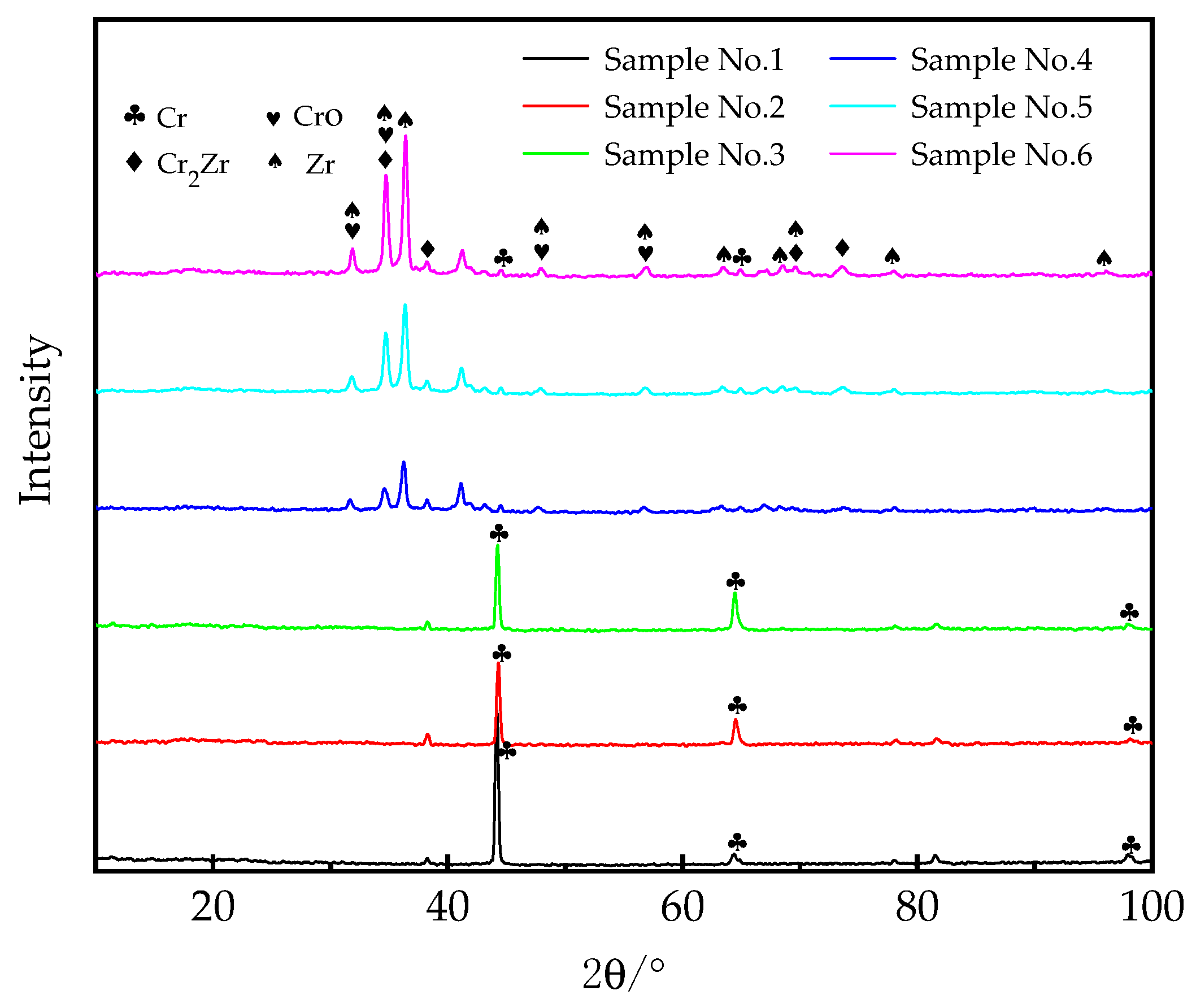
3.2. Composition Analysis

To determine phases of the coating, we performed XRD analysis (Figure 5), which indicated that the phase of the coating prepared with the lower laser energy densities (lower than 11.25 × 10⁴ J/cm2) remains Cr without any change while the peeks of Zr, CrO, Cr2Zr are detected in the coating prepared by the higher laser energy densities (higher than 13.5 × 10⁴ J/cm2). α -Cr2Zr is formed at the temperature range from 973 and 1835 K, while β -Cr2 Zr is generated between 1835 and 1895 K, and γ -Cr2 Zr is generated between 1895 and 1946 K. The forming of Cr2Zr indicates that laser high energy density can promote the diffusion and fusion of coating Cr and substrate Zr alloy.

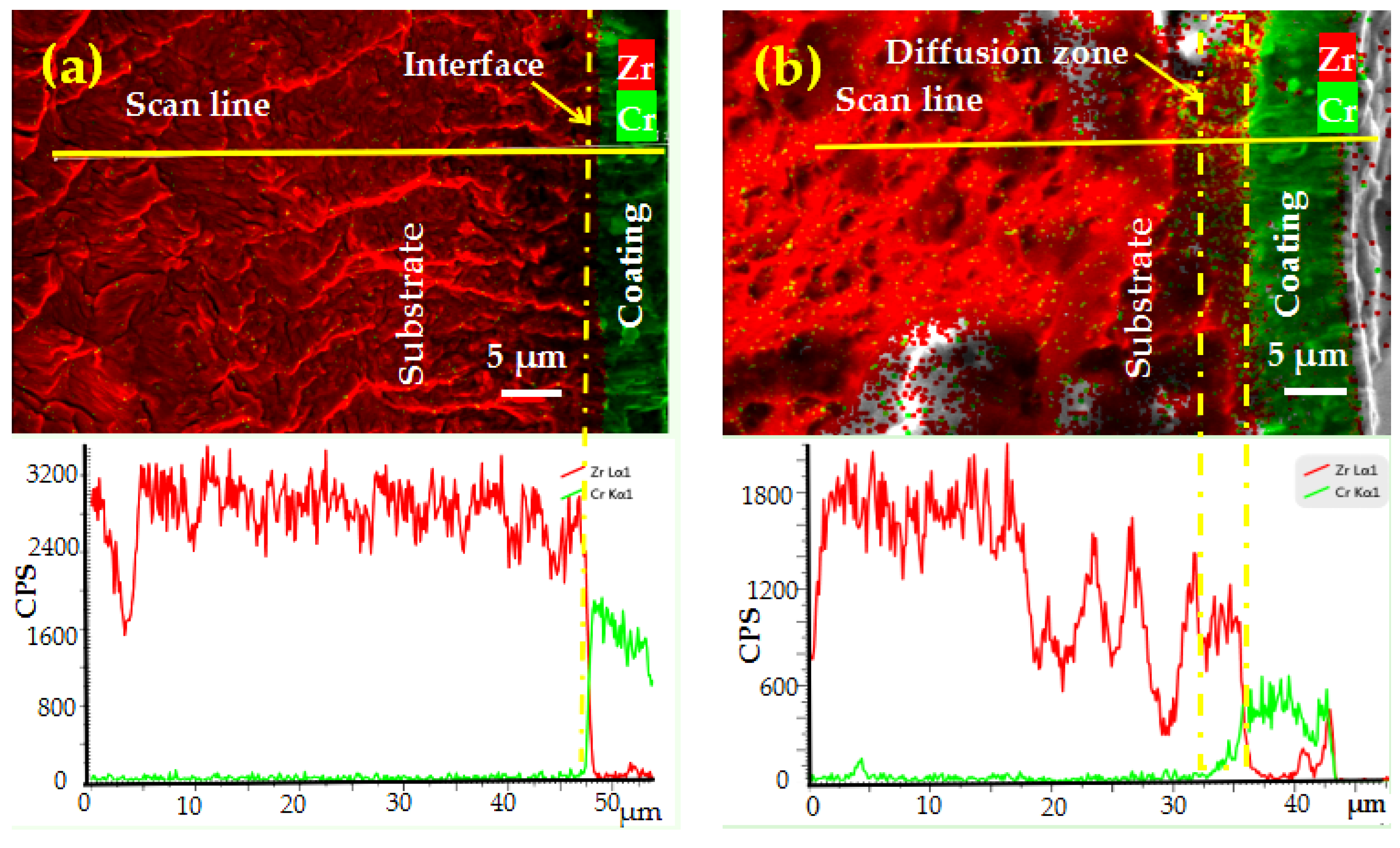
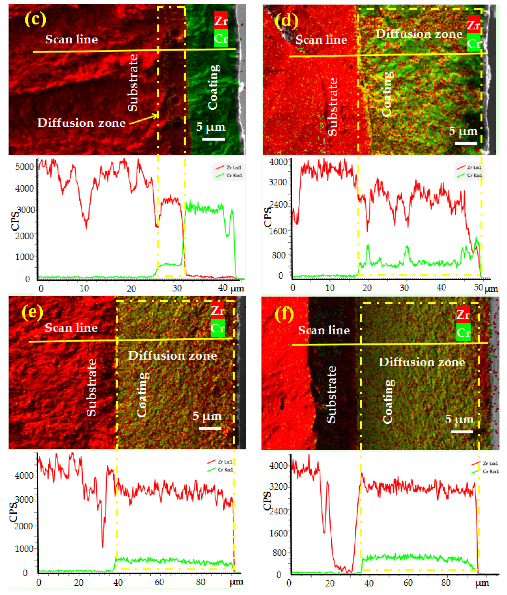
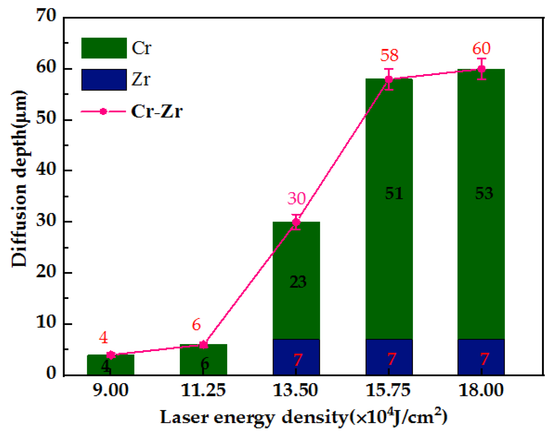
3.3. Membrane-Base Interface Diffusion Analysis

Figure 6 shows the SEM and corresponding EDS of the tensile fracture of the specimens. The element diffusion depth was calculated by scanning the element line of the sample cross section. From Figure 7, we can see that the Cr coating thickness of sample No. 1 was uniform ~7 μm, the interface between the coating and the substrate was observed clearly, indicating that the coating and substrate is physically bonded. When the laser energy density was 9 × 10⁴ J/cm2 and 11.25 × 10⁴ J/cm2, a Cr diffusion layer was found with the thickness of 4–6 μm near the interface of the coating and substrate which leads to the blurring of the interface, as shown in Figure 7. When the laser energy density increases to 13.5 × 10⁴ J/cm2, Zr signals were detected on the surface of the coating, indicating that a Zr-Cr fusion zone with a thickness of 30 μm was formed, and the Cr coating completely melts and the substrate Zr partially melts, which is consistent with the simulation results. The ratio of the thickness of the diffusion layer to the whole coating of sample Nos. 1–6 was 0%, 36.4%, 46.2%, 100%, 100% and 100%, respectively. The thickness of the diffusion layer influences the oxidation resistance of the coating at high temperature.

3.4. Tensile Fracture Morphology

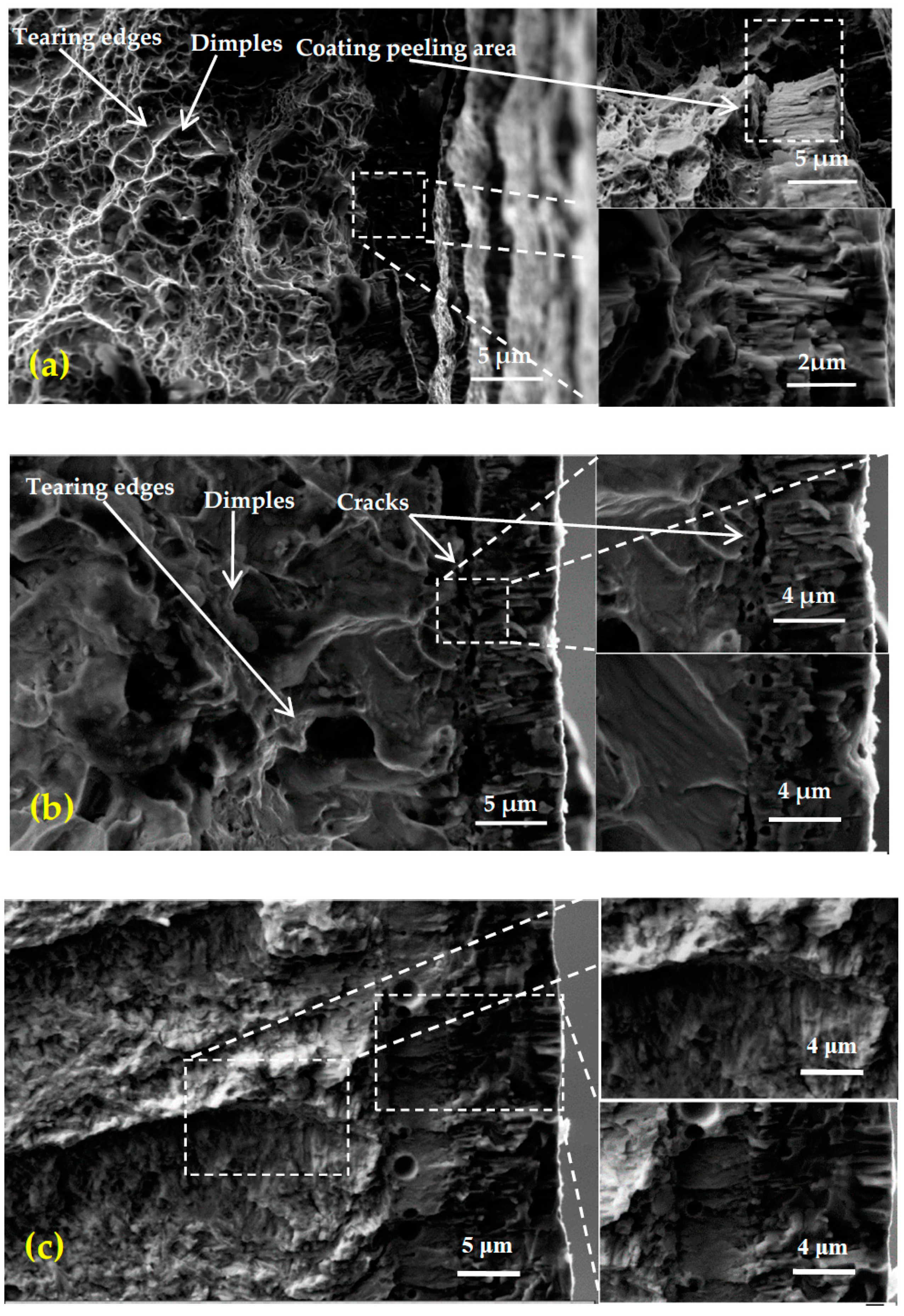
3.4.1. Microstructure of Tensile Fracture

The tensile fracture of the Zr-4 alloy is a ductile fracture [19], while no dimples were observed in the tensile fracture of the chromium coating indicating that the chromium coating was brittle (Figure 8a). This is mainly due to the multi-arc ion plating Cr coating being formed by the deposition and superposition of sputtering particles. The crack distribution is at the interface of the coating and substrate in the fracture of the sample No. 2, while there is no crack in the layers of coating/substrate in sample No. 3 (Figure 8c), sample No. 4 (Figure 8d), sample No. 5 (Figure 8e) and sample No. 6 (Figure 8f). In addition, dimples were found in the fracture of sample No. 6 (Figure 8f), mainly because the Cr and Zr diffused at the interface of the coating and substrate prepared by the multi-arc ion Cr plating using high-energy laser, and formed an interfusion diffusion zone. At the same time, the crack originated from the subsurface layer of columnar crystal region rather than the coating surface layer of fine crystal region.

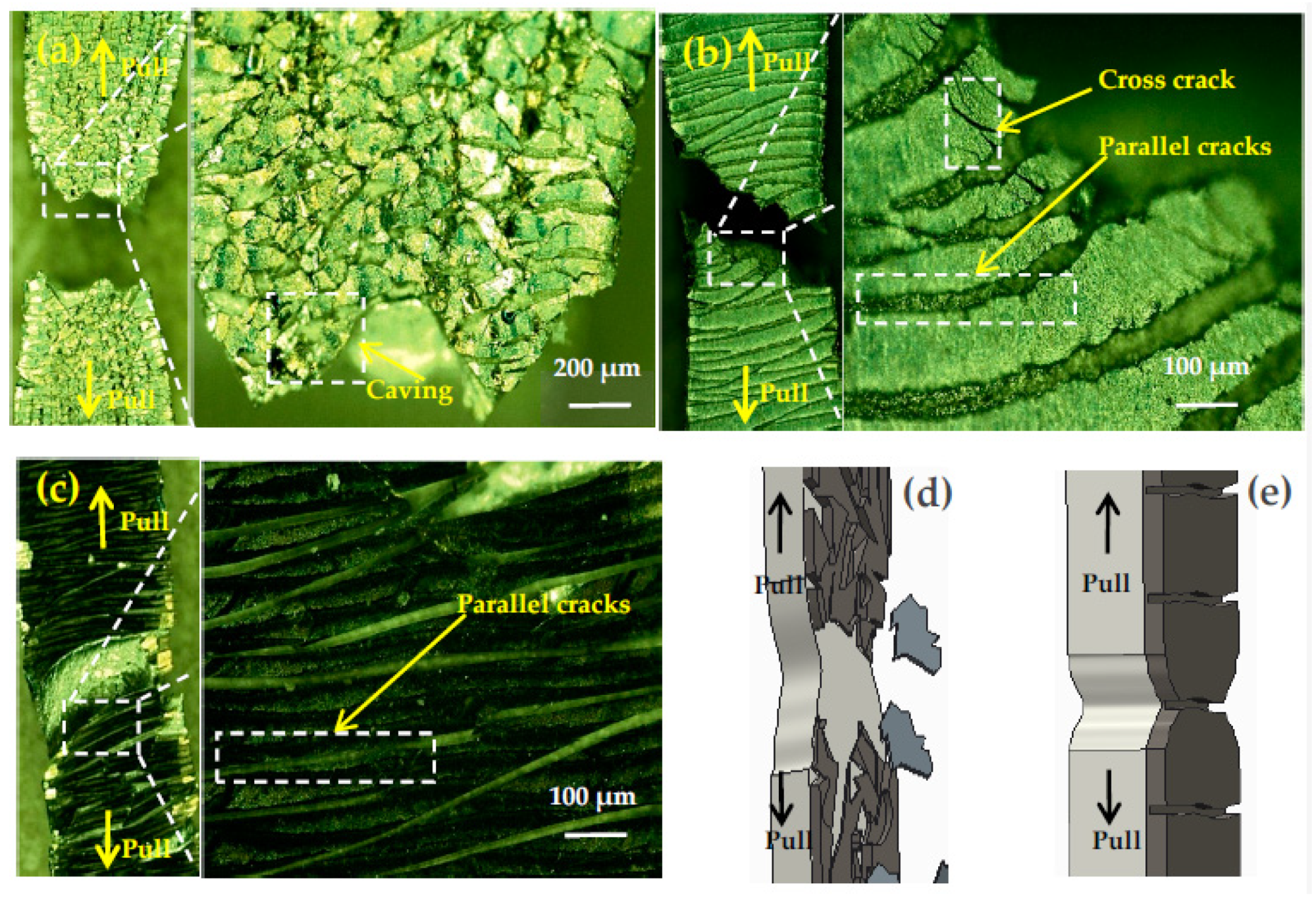
3.4.2. Surface Fracture Morphology of Tensile Specimen

The tensile specimen coating surface morphology of each samples are shown in Figure 9. The sample No. 1 was not subjected to laser fusion treatment, and there were many cross cracks on its coating surface. Meanwhile, the coating near the fracture breaks off. The coating surface of sample No. 6 (Figure 9c) cracked laterally and in parallel with the direction of the crack perpendicular to the direction of the tensile force without falling off, as shown in Figure 9e (schematic diagram), indicating that the coating bonding performance of sample No. 6 was improved. In addition, there are both transverse parallel cracks and cross microcracks in sample No. 4, indicating that the coating bonding performance of sample No. 4 is superior to that of sample No. 1 and inferior to that of sample No. 6. From the above analysis, it can be shown that the laser melting process is conducive to improving the bonding performance of the coating, which increases with the increase of laser energy density. In Figure 9d, we indicate that the coating of sample No. 1 had poor adhesion while the combination performance of the coating fabricated by laser is greatly improved.

3.5. Surface Characterization

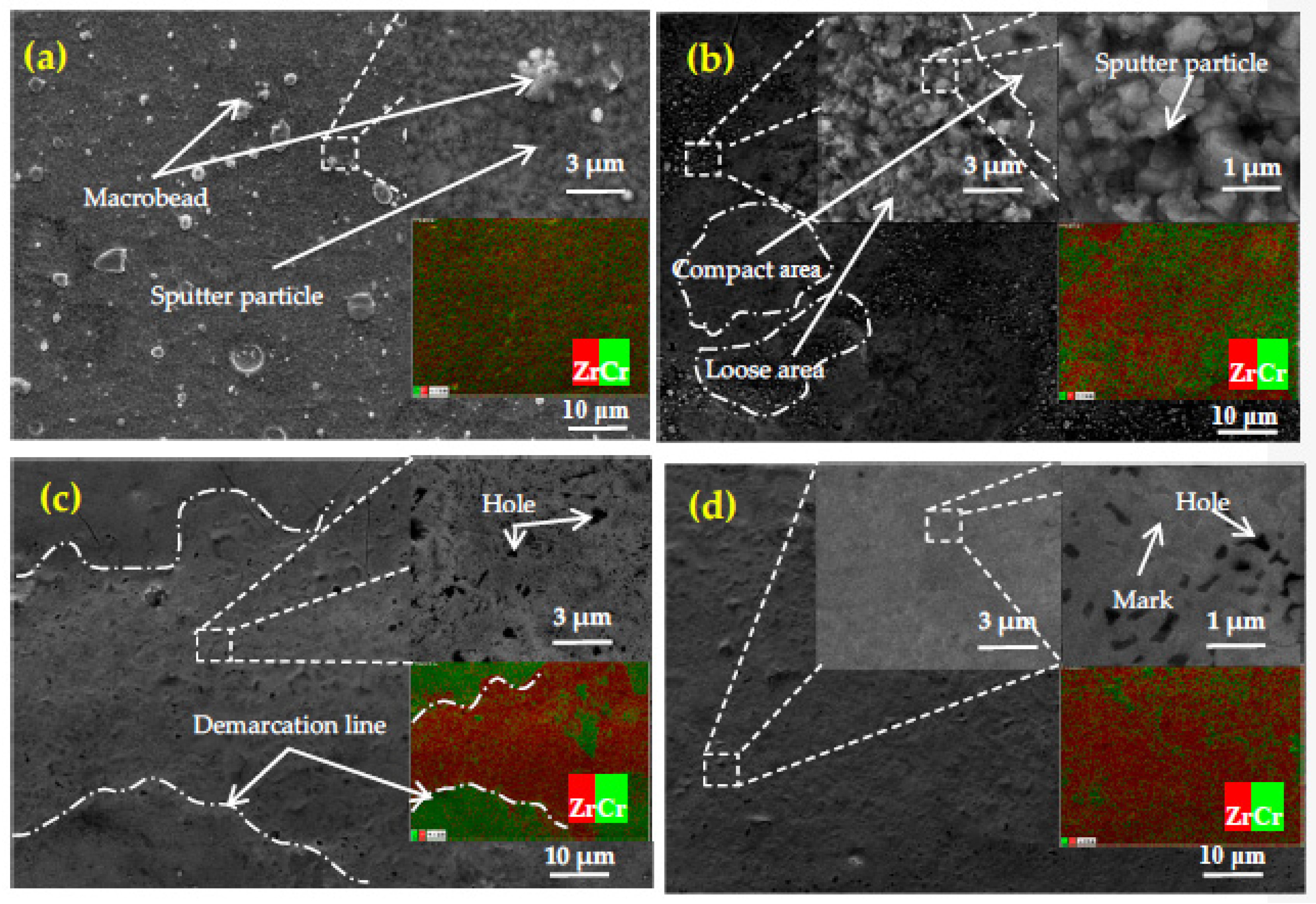
3.5.1. Surface Morphology

The solidified particles are observed on the surface of sample No.1 (Figure 10a) showing typical characteristics of multi-arc ion plating coating [8]. The large particles on the surface of sample No. 4 (Figure 10b) were significantly reduced. At the same time, the local area of the sample showed obvious loose areas and dense areas. Sputtering particles in the loose area have sharp edges and corners, and the number of holes and particles increase. The dense area of the coating is smooth and flat, but the original structure of sputtering particle deposition has not changed. The stronger Zr signal was detected in the dense region of the coating, indicating that the higher the effective energy density of the laser absorbed in this region, the higher the diffusion degree of Zr. The surface of the sample No. 5 (Figure 10c) is relatively flat, with no particles and smaller porosity. The strong Zr peak on the coating surface showed obvious uneven distribution, which was completely different from sample 4. Areas with a strong Zr peak are rougher than areas with a strong Cr peak due to small burrs. The coating surface of sample No. 6 (Figure 10d) is smooth and flat, with almost no holes or particles. The tiny burrs generated by Zr diffusion near the coating surface are evenly distributed, and the burrs become smaller. At the same time, it was found that the Zr peak was relatively strong and evenly distributed on the entire coating surface. However, from the locally enlarged picture of Figure 10d we can see the marks and holes left after the particles were cooled by micro-melting.

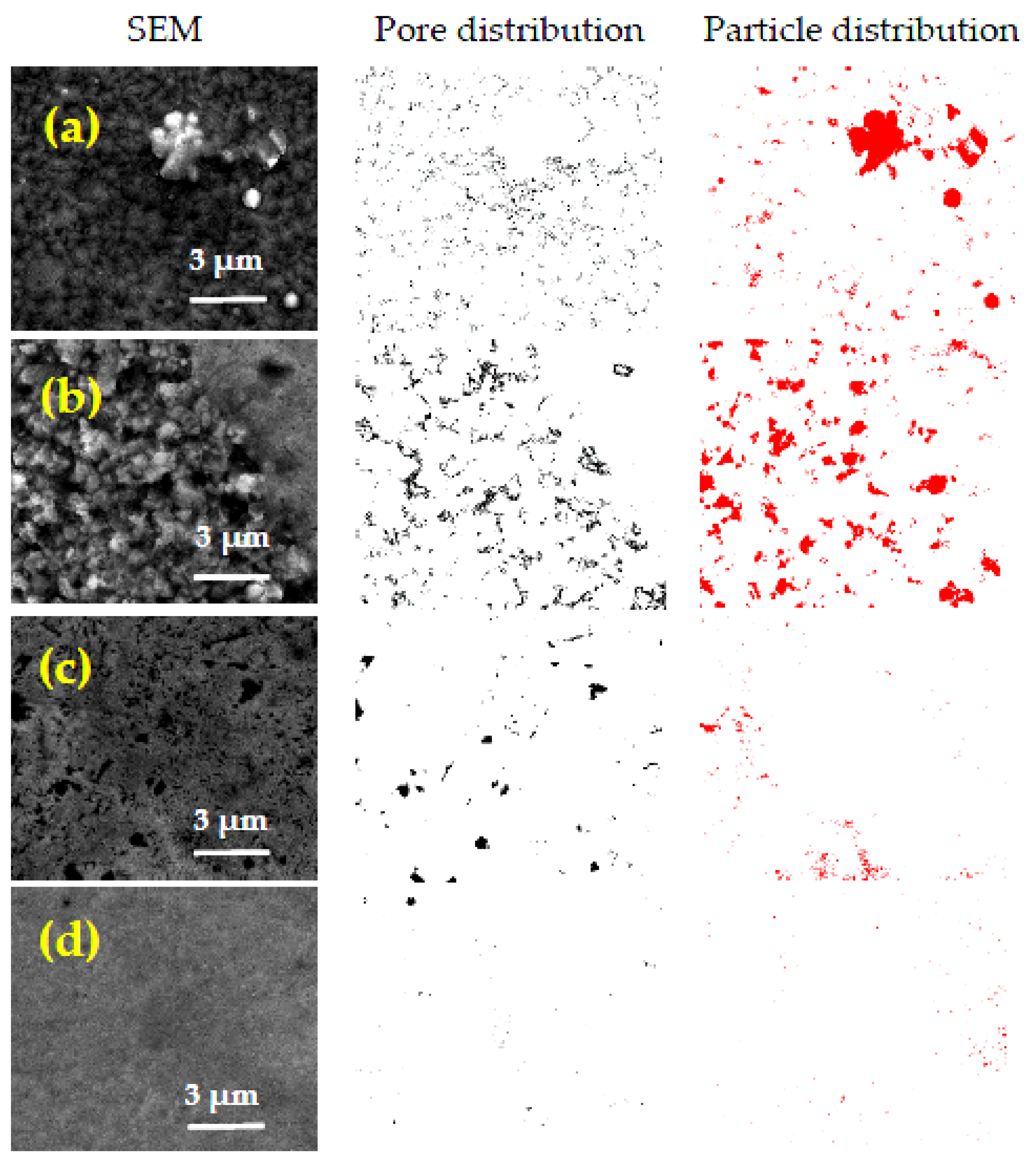
3.5.2. Comparative Analysis of Surface Pores and Particles

We adopted Image J software to analyze the surface density of the coating after laser micro-melting by counting the holes, particle distribution and area proportion of the coating. As can be seen from Figure 11 and Table 4, the proportion of the hole area is 4.6%, 6.8%, 1.9% and 0.3%, respectively. The proportion of particle area was 7%, 10.1%, 1.4% and 0.4%, respectively. This indicates that the laser energy density is a critical value at 13.5 × 10⁴ J/cm2. When the laser energy density is higher than this critical value, the sputtering particles on the coating surface or even the whole coating melts, and the holes are significantly reduced, so the coating surface density is high. When it is lower than this critical value, the coating will oxidize because the surface temperature of the coating is not high enough to melt the sputtering particles. At the same time, the edges and corners of sputtering particles are oxidized seriously due to the rapid temperature rise, so that the flat sputtering particles are oxidized into particles, and the holes and particle area proportion are increased and the surface density is reduced.

4. Conclusions

We adopted laser micro-melting multi-arc ion plating process to fabricate coating with high surface density successfully, and investigated the effect of laser energy density on the coating structure. It is found that under the low power density laser irradiation (9 × 10⁴ J/cm2), the highest temperature of the samples are lower than that of the Cr and Zr melting point, but the temperature at the interface between the coating and substrate exceeds the minimum melting point of Cr-Zr eutectic alloy, the Cr of the coating diffuses slightly, forming a diffusion depth of about 4 μm. In addition, the particle oxidation of sputtering on the coating surface increases the proportion of holes and particle area and decreases the surface density. However, when the laser energy density increased to 13.5 × 10⁴ J/cm2, the substrate Zr partially melts and spreads to the whole Cr coating, forming a Zr-Cr fusion zone with the thickness of 30 μm, which is conducive to the refinement of surface particles and the reduction of pores, so as to increase the surface density. When the laser energy density is up to 18 × 104 J/cm2, the coating is closely bound to the substrate without cracks, forming fluttering protrusions at the membrane base interface, and shallow and small dimples appear in the middle part of the coating. The coating surface shows parallel cracking without peeling. The coating shows good toughness, and the interface is transformed into an interface metallurgical bonding, which is beneficial to improve the bonding performance.

Author Contributions

C.Q. conceived and designed the research; L.H. wrote the paper and carried out the experiments; Y.C., H.L. (Huailin Li), and H.L. (Hao Liu) entered the discussion. All authors have read and agreed to the published version of the manuscript.

Funding

This research was funded by Major Projects of National Science and Technology of China (Grant No. 2015ZX06004001-002); Natural Science Foundation of Hunan Province of China (Grant No. 2019JJ50529), Hunan Education Department Project (Grant No. 18K074); Open fund project of Hunan Collaborative Innovation Center for nuclear fuel cycle technology and equipment (Grant No. 2019KFY08), Key project of Hunan Provincial Education Department (Grant No. 19A424).

Conflicts of Interest

The authors declare no conflict of interest.

References

  1. Terrani, K.A. Accident tolerant fuel cladding development: Promise, status, and challenges. J. Nucl. Mater. 2018, 501, 13–30. [Google Scholar] [CrossRef]
  2. Khatkhatay, F.; Jiao, L.; Jian, J.; Zhang, W.; Jiao, Z.; Gan, J.; Zhang, H.; Zhang, X.; Wang, H. Superior corrosion resistance properties of TiN-based coatings on Zircaloy tubes in supercritical water. J. Nucl. Mater. 2014, 451, 346–351. [Google Scholar] [CrossRef]
  3. Daub, K.; Van Nieuwenhove, R.; Nordin, H. Investigation of the impact of coatings on corrosion and hydrogen uptake of Zircaloy-4. J. Nucl. Mater. 2015, 467, 260–270. [Google Scholar] [CrossRef]
  4. Zinkle, S.J.; Terrani, K.A.; Gehin, J.C.; Ott, L.J.; Snead, L.L. Accident tolerant fuels for LWRs: A perspective. J. Nucl. Mater. 2014, 448, 374–379. [Google Scholar] [CrossRef]
  5. Brown, N.R.; Wysocki, A.J.; Terrani, K.A.; Xu, K.G.; Wachs, D.M. The potential impact of enhanced accident tolerant cladding materials on reactivity initiated accidents in light water reactors. Ann. Nucl. Energy 2017, 99, 353–365. [Google Scholar] [CrossRef] [Green Version]
  6. Tang, C.; Stueber, M.; Seifert, H.J.; Steinbrueck, M. Protective coatings on zirconium-based alloys as accident-tolerant fuel (ATF) claddings. Corros. Rev. 2017, 35, 141–165. [Google Scholar] [CrossRef]
  7. Kim, H.-G.; Kim, I.-H.; Jung, Y.-I.; Park, D.-J.; Park, J.-Y.; Koo, Y.-H. Adhesion property and high-temperature oxidation behavior of Cr-coated Zircaloy-4 cladding tube prepared by 3D laser coating. J. Nucl. Mater. 2015, 465, 531–539. [Google Scholar] [CrossRef]
  8. Kim, H.-G.; Yang, J.-H.; Kim, W.-J.; Koo, Y.-H. Development Status of Accident-tolerant Fuel for Light Water Reactors in Korea. Nucl. Eng. Technol. 2016, 48, 1–15. [Google Scholar] [CrossRef] [Green Version]
  9. Koo, Y.-H.; Yang, J.-H.; Park, J.-Y.; Kim, K.-S.; Kim, H.-G.; Kim, D.-J.; Jung, Y.-I.; Song, K.-W. KAERI’s Development of LWR Accident-Tolerant Fuel. Nucl. Technol. 2017, 186, 295–304. [Google Scholar] [CrossRef]
  10. Pint, B.A.; Terrani, K.A.; Yamamoto, Y.; Snead, L.L. Material Selection for Accident Tolerant Fuel Cladding. Metall. Mater. Trans. E 2015, 2, 190–196. [Google Scholar] [CrossRef] [Green Version]
  11. Zhang, W.; Tang, R.; Yang, Z.B.; Liu, C.H.; Chang, H.; Yang, J.J.; Liao, J.L.; Yang, Y.Y.; Liu, N. Preparation, structure, and properties of an AlCrMoNbZr high-entropy alloy coating for accident-tolerant fuel cladding. Surf. Coat. Technol. 2018, 347, 13–19. [Google Scholar] [CrossRef]
  12. Ma, X.-F.; Wu, Y.-W.; Tan, J.; Meng, C.-Y.; Yang, L.; Dang, W.-A.; He, X.-J. Evaluation of corrosion and oxidation behaviors of TiAlCrN coatings for nuclear fuel cladding. Surf. Coat. Technol. 2019, 358, 521–530. [Google Scholar] [CrossRef]
  13. Bischoff, J.; Delafoy, C.; Vauglin, C.; Barberis, P.; Roubeyrie, C.; Perche, D.; Duthoo, D.; Schuster, F.; Brachet, J.-C.; Schweitzer, E.W.; et al. AREVA NP’s enhanced accident-tolerant fuel developments: Focus on Cr-coated M5 cladding. Nucl. Eng. Technol. 2018, 50, 223–228. [Google Scholar] [CrossRef]
  14. Jiang, L.; Xiu, P.; Yan, Y.; Lu, C.; Huang, M.; Liu, T.; Ye, C.; Sun, H.; Shu, R.; Wang, L. Effects of ion irradiation on chromium coatings of various thicknesses on a zirconium alloy. J. Nucl. Mater. 2019, 526. [Google Scholar] [CrossRef]
  15. Zhong, W.; Mouche, P.A.; Heuser, B.J. Response of Cr and Cr-Al coatings on Zircaloy-2 to high temperature steam. J. Nucl. Mater. 2018, 498, 137–148. [Google Scholar] [CrossRef]
  16. Alat, E.; Motta, A.T.; Comstock, R.J.; Partezana, J.M.; Wolfe, D.E. Ceramic coating for corrosion (c3) resistance of nuclear fuel cladding. Surf. Coat. Technol. 2015, 281, 133–143. [Google Scholar] [CrossRef] [Green Version]
  17. He, X.; Tian, Z.; Shi, B.; Xu, X.; Meng, C.; Dang, W.; Tan, J.; Ma, X. Effect of gas pressure and bias potential on oxidation resistance of Cr coatings. Ann. Nucl. Energy 2019, 132, 243–248. [Google Scholar] [CrossRef]
  18. Park, J.-H.; Kim, H.-G.; Park, J.-y.; Jung, Y.-I.; Park, D.-J.; Koo, Y.-H. High temperature steam-oxidation behavior of arc ion plated Cr coatings for accident tolerant fuel claddings. Surf. Coat. Technol. 2015, 280, 256–259. [Google Scholar] [CrossRef]
  19. Niu, Y.; Wei, J.; Yu, Z. Microstructure and tribological behavior of multilayered CrN coating by arc ion plating. Surf. Coat. Technol. 2015, 275, 332–340. [Google Scholar] [CrossRef]
  20. Kuprin, A.S.; Belous, V.A.; Voyevodin, V.N.; Bryk, V.V.; Vasilenko, R.L.; Ovcharenko, V.D.; Reshetnyak, E.N.; Tolmachova, G.N.; V’Yugov, P.N. Vacuum-arc chromium-based coatings for protection of zirconium alloys from the high-temperature oxidation in air. J. Nucl. Mater. 2015, 465, 400–406. [Google Scholar] [CrossRef]
  21. Yeom, H.; Maier, B.; Mariani, R.; Bai, D.; Fronek, S.; Xu, P.; Sridharan, K. Magnetron sputter deposition of zirconium-silicide coating for mitigating high temperature oxidation of zirconium-alloy. Surf. Coat. Technol. 2017, 316, 30–38. [Google Scholar] [CrossRef] [Green Version]
  22. Lee, Y.; Lee, J.I.; No, H.C. Mechanical analysis of surface-coated zircaloy cladding. Nucl. Eng. Technol. 2017, 49, 1031–1043. [Google Scholar] [CrossRef]
  23. Park, D.J.; Kim, H.G.; Jung, Y.I.; Park, J.H.; Yang, J.H.; Koo, Y.H. Behavior of an improved Zr fuel cladding with oxidation resistant coating under loss-of-coolant accident conditions. J. Nucl. Mater. 2016, 482, 75–82. [Google Scholar] [CrossRef]
  24. Sridharan, K.; Harrington, S.P.; Johnson, A.K.; Licht, J.R.; Anderson, M.H.; Allen, T.R. Oxidation of plasma surface modified zirconium alloy in pressurized high temperature water. Mater. Des. 2007, 28, 1177–1185. [Google Scholar] [CrossRef]
  25. Krishnan, R.; Dash, S.; Kesavamoorthy, R.; Babu Rao, C.; Tyagi, A.K.; Raj, B. Laser surface modification and characterization of air plasma sprayed alumina coatings. Surf. Coat. Technol. 2006, 200, 2791–2799. [Google Scholar] [CrossRef]
  26. Kim, H.-G.; Kim, I.-H.; Jung, Y.-I.; Park, D.-J.; Park, J.-Y.; Koo, Y.-H. Microstructure and Mechanical Strength of Surface Ods Treated Zircaloy-4 Sheet Using Laser Beam Scanning. Nucl. Eng. Technol. 2014, 46, 521–528. [Google Scholar] [CrossRef] [Green Version]
  27. Yeom, H.; Hauch, B.; Cao, G.; Garcia-Diaz, B.; Martinez-Rodriguez, M.; Colon-Mercado, H.; Olson, L.; Sridharan, K. Laser surface annealing and characterization of Ti2AlC plasma vapor deposition coating on zirconium-alloy substrate. Thin Solid Film. 2016, 615, 202–209. [Google Scholar] [CrossRef] [Green Version]
  28. Chen, S.; Yuan, C. Neutronic Analysis on Potential Accident Tolerant Fuel-Cladding Combination U3Si2-FeCrAl. Sci. Technol. Nucl. Install. 2017, 2017, 1–12. [Google Scholar] [CrossRef] [Green Version]
  29. Chen, Y.; Hu, L.; Qiu, C.; He, B.; Zhou, L.; Zhao, J.; Li, Y. Influence of LBE Temperatures on the Microstructure and Properties of Crystalline and Amorphous Multiphase Ceramic Coatings. Coatings 2019, 9, 543. [Google Scholar] [CrossRef] [Green Version]
  30. Murabayashi, M.; Tanaka, S.; Takahashi, Y. Thermal Conductivity and Heat Capacity of Zircaloy-2, −4 and Unalloyed Zirconium. J. Nucl. Sci. Technol. 1975, 12, 661–662. [Google Scholar] [CrossRef]
Figure 1. Temperature field simulation analysis model of Cr coating laser melting treatment.
Coatings 10 00565 g001
Figure 2. Schematic diagram (a) and the apparatus of quartz glass atmosphere protection device (b) for laser melting.
Coatings 10 00565 g002
Figure 3. Sample No. 3 (a), No. 4 (b), No. 5 (c), No. 6 (d) of temperature nephogram for laser melting simulation.
Coatings 10 00565 g003
Figure 4. The relationship between the maximum temperature of the coating surface and Cr/Zr interface (a), the molten depth of Cr coating and Zr substrate (b), the molten width of the coating surface (c). The molten width of the Cr/Zr interface and laser energy density is obtained by laser melting simulation (d).
Coatings 10 00565 g004
Figure 5. X-ray diffraction pattern of the Cr coatings on Zr-4 substrates surface at different laser power densities.
Coatings 10 00565 g005
Figure 6. The SEM and corresponding energy disperse spectroscopy (EDS) of the tensile fracture of sample No. 1 (a), sample No. 2 (b), sample No. 3 (c), sample No. 4 (d), sample No. 5 (e), sample No. 6 (f).
Coatings 10 00565 g006aCoatings 10 00565 g006b
Figure 7. Diffusion depth.
Coatings 10 00565 g007
Figure 8. SEM comparison of fatigue fracture of sample No. 1 (a), sample No. 2 (b), sample No. 3 (c), sample No. 4 (d), sample No. 5 (e), sample No. 6 (f).
Coatings 10 00565 g008aCoatings 10 00565 g008b
Figure 9. The tensile specimen coating surface morphology of sample No. 1 (a), sample No. 4 (b), sample No. 6 (c), schematic diagram of brittle fracture (d) and ductile fracture (e).
Coatings 10 00565 g009
Figure 10. SEM and EDS for coating surface of sample No. 1 (a), sample No. 4 (b), sample No. 5 (c), sample No. 6 (d).
Coatings 10 00565 g010
Figure 11. Pore and particle distribution for SEM treated of sample No. 1 (a), sample No. 4 (b), sample No. 5 (c), sample No. 6 (d) by Image J.
Coatings 10 00565 g011
Table 1. Preparation process parameters of Cr coating deposited by multi-arc ion plating.
Target Material Gas Pressure/(×10−3 Pa)Pulsed Bias/VArc Current/ASubstrate Temperature/°CArgon Flow/(mL·min−1)Deposition Time/h
Cr<6.0−200654001106
Table 2. Thermophysical properties of Cr and Zr-4 alloy [30].
MaterialMelting Point/KDensity/Kg/m3Melting Heat/(×KJ/Kg)Thermal Radiation Coefficient (293 K)Specific Heat Capacity J/(Kg·K)Thermal Conductivity/W/(m·K)
Cr213071903250.345093.7
Zr-4210065604680.3//
Table 3. Process parameters of Cr coating laser melting.
SamplePower/WEnergy Density/(×104 J/cm2)Spot Diameter/mmVelocity of Scanning/(mm·min−1)Distance between Laps/mm
1#000.116000.06
2#249
3#3011.25
4#3613.50
5#4215.75
6#4818
Table 4. Pore and particle area ratio for SEM by Image J.
TypeSample No. 1Sample No. 4Sample No. 5Sample No. 6
Pore 4.6%6.8%1.9%0.3%
Particle7.0%10.1%1.4%0.4%

