Article

Micro-Patterning of Magnetron Sputtered Titanium Dioxide Coatings and Their Efficiency for Photocatalytic Applications

Surface Engineering Group, School of Engineering, Manchester Metropolitan University, Manchester M1 5GD, UK
*
Author to whom correspondence should be addressed.
Coatings 2020, 10(1), 68; https://doi.org/10.3390/coatings10010068
Submission received: 17 December 2019 / Revised: 7 January 2020 / Accepted: 9 January 2020 / Published: 12 January 2020
(This article belongs to the Special Issue Photocatalytic Thin Films)

Abstract

:
Titanium dioxide thin films were deposited onto sola-lime glass substrates by reactive magnetron sputtering. Fine stainless steel mesh sheets with different aperture sizes were applied as masks over glass substrates to allow the deposition of the coatings with micro-patterned structures and, therefore, enhanced surface area. Non-patterned titania films were deposited for comparison purposes. The titanium dioxide films were post-deposition annealed at 873 K for crystallinity development and then extensively analysed by a number of analytical techniques, including scanning electron microscopy (SEM)/energy-dispersive X-ray spectroscopy (EDX), optical and stylus profilometry, X-ray diffraction (XRD), X-ray photoelectron spectroscopy (XPS), and UV-Vis spectroscopy. The photocatalytic activity of non-patterned and micro-patterned titania films was assessed under UV light irradiation by three different methods; namely methylene blue, stearic acid, and oleic acid degradation. The results revealed that the micro-patterned coatings significantly outperformed non-patterned titania in all types of photocatalytic tests, due to their higher values of surface area. Increasing the aperture of the stainless steel mesh resulted in lower photocatalytic activity and lower surface area values, compared to the coatings deposited through a smaller aperture mesh.

1. Introduction

Over the past few decades photocatalytic processes have gained recognition as simple, yet sustainable methods of air/water/surface depollution and disinfection [1,2,3,4]. Despite the fact that the overall focus of photocatalytic research seems to be shifting towards the discovery of novel photocatalytic materials [5], conventional titanium dioxide (or titania)-based photocatalytic materials still remain by far the most studied and practically used photocatalysts, owing to the low cost of the material, high chemical and biological stability, and low toxicity [6]. Titanium dioxide -based photocatalytic surfaces find practical applications in such fields as self-cleaning surfaces, building materials, antimicrobial materials, and non-fogging surfaces [7]. It is clear that, for an efficient photocatalytic process, the area of contact between the catalyst and the pollutant should be rather high.
It is not surprising, therefore, that nanoparticulated titania photocatalysts still remain the material of choice for high throughput processes, with Degussa P25 still being reported as the most used commercial photocatalyst. Despite the efficiency of particulated photocatalysts, their use requires a post-treatment separation step, which may be a serious limitation on their applicability. This is of extreme importance in the light of the recent conclusions of the European Chemicals Agency (ECHA), which indicates that nanoparticulated titanium dioxide may have a carcinogenic effect [8]. Consequently, the immobilisation of titanium dioxide on surfaces by either chemical or physical methods or a combination of both has become an important task [9]. Thus, the majority of titanium dioxide photocatalytic coatings are currently being prepared by sol-gel [10,11], hydrothermal methods [12,13], and chemical [14,15]/physical [16,17,18] vapour deposition techniques.
Of the techniques outlined above, physical vapour deposition, and in particular magnetron sputtering, is frequently reported as a method of choice for the production of photocatalytic titanium dioxide films [16,19,20,21]. Compared to chemical deposition methods, magnetron sputtering offers a number of advantages, such as coating uniformity over large areas, good control over chemical and morphological properties of the films, lack of toxic or hazardous precursors involved, and excellent scalability [22]. Also, according to certain studies, magnetron sputtering offers an additional advantage of higher durability of titanium dioxide films, compared to, e.g., sol-gel techniques [23]. Not surprisingly, magnetron sputtering is widely used for the industrial production of commercially-available photocatalytic products, such as self-cleaning glazing products [24]. While a detailed description of the process can be found elsewhere [22], in brief, magnetron sputtering involves the removal (‘sputtering’) of metal atoms from a negatively-biased solid target by bombardment from positively charged ions (usually argon) generated in a glow discharge plasma, followed by the condensation of the target atoms on the substrate to form a thin film. Reactive gases, such as oxygen, can be introduced to the process to react with the sputtered metal atoms, resulting in oxide film formation.
Sputtered coatings are usually conformal to their substrate, which means that their surface area is very similar to that of the uncoated substrate. As a result, thin solid film photocatalysts deposited onto plane surfaces cannot provide surface areas comparable to nanoparticulated materials. Therefore, a plethora of techniques aimed at increasing the available surface area are being developed and tested. Frequently reported methods include surface structuring techniques, such as the formation of nanocolumns and nanorods [25,26], surface etching [27], oblique angle deposition [28,29], the use of high surface area substrate materials [30], etc. While each of these techniques has, to a certain extent, proven to successfully increase surface area of the photocatalysts, their practical application is very limited. Most of these methods are not necessarily suitable for up-scaling, but rather limited to laboratory scale deposition.
Here we present and assess the efficiency of increasing the surface area of photocatalytic titania coatings using patterning via masked deposition. The idea of masked deposition is not new on its own right; it has been mentioned in several patents—e.g., in the 2004 Atobe and Yotsuya United States patent for masked vacuum deposition for display panels and electronic devices [31], while in 2005 Nichols and Mosier patented masked magnetron sputter deposition for altering coating uniformity or non-uniformity [32]. While several papers mention patterned titanium dioxide surfaces, they typically use polymer/colloidal masks that have to be dissolved/removed post-deposition [33,34,35].
Instead, we have attempted to use fine stainless steel mesh as a mask to obtain micro-patterned titanium dioxide surfaces with higher surface areas in a one-step process by reactive magnetron sputter deposition onto glass substrates. Non-patterned titania coatings (produced without a mesh) were deposited for comparison purposes. The coatings were then analysed by a number of analytical techniques, including their photocatalytic properties, both in aqueous solution (dye degradation), and through direct contact with a model pollutant (stearic acid and oleic acid degradation).

2. Materials and Methods

2.1. Deposition

Coating deposition was performed in a Teer UDP350 sputtering rig (Teer Coatings Ltd., Droitwich, UK), the schematic of the rig can be found elsewhere [36]. In brief, the deposition was performed from one 300 mm × 100 mm type II unbalanced planar magnetron, installed through the chamber wall. A directly cooled titanium (99.5% purity) target was installed on the magnetron. A base pressure of 2 × 10⁻³ Pa or below was achieved through a combination of rotary (Edwards 40) and turbomolecular (Leybold i450) pumps. The magnetron was driven in pulsed DC mode, using an Advanced Energy Pinnacle plus power supply at 1 kW time-averaged power, 100 kHz pulse frequency and a duty cycle of 50% for all deposition runs. The deposition process was carried out in an argon-oxygen atmosphere, at a working pressure of 0.3 Pa. The Ar flow was controlled via a mass-flow controller and set at 15 sccm, while the flow of oxygen was controlled via optical emission monitoring at 25% of full-metal-signal setpoint. The deposition time was 2 h for all produced films.
The distance between the substrate and the magnetron was 10 cm. The depositions were performed onto soda-lime glass; the substrate was ultrasonically pre-cleaned in acetone and methanol prior to the deposition (all chemicals used for this work were purchased from Sigma Aldrich, St. Louis, MO, USA). The substrate was composed of a stainless steel backplate, a soda-lime glass slide and a sheet of stainless steel mesh clamped together. A schematic representation of the substrate arrangement is given in Figure 1. Four types of fine SS316 grade stainless steel (purchased from the Mesh Company, Warrington, UK) were used for production of patterned titania coatings. The overview of the mesh types used is given in the Table 1. Non-patterned titania coatings were deposited for comparison purposes by using the same substrate arrangement, but without the stainless steel mesh layer.
All as-deposited coatings were amorphous, therefore a post-deposition annealing step was required to develop crystallinity. The samples were post-deposition isothermally annealed for 30 min at 873 K (annealing temperature was pre-defined experimentally earlier [17]) in air for crystal structure development and then allowed to cool gradually in air for 10 h to avoid the formation of thermal stresses in the coatings (experimentally pre-defined cooling regime).

2.2. Characterisation of the Coatings

The thickness of the coatings was measured with stylus profilometry (DektakTM (Bruker, Billerica, MA, USA)) and then verified with optical profilometry (ProFilm 3D, Filmetrics, San Diego, CA, USA). The coating compositions were studied with energy-dispersive X-ray spectroscopy (EDX) (EDAX Trident installed on a Zeiss Supra 40 VP-FEG-SEM, Edax Co., Mahwah, NJ, USA). Images of the films were obtained with scanning electron microscopy (SEM) (Zeiss Supra 40 VP-FEG-SEM, Zeiss Microscopy, Jena, Germany). Surface areas were calculated using the optical profilometry (ProFilm 3D, Filmetrics) images. The crystallinity of the coatings was studied using X-ray diffraction (XRD) (Panalytical Xpert powder with CuKa1 radiation at 0.154 nm, in grazing incidence mode at a 3° angle of incidence over a scan range from 20° to 70° 2θ; the accelerating voltage and applied current were 40 kV and 30 mA, respectively). The oxidation state information was obtained with X-ray photoelectron spectroscopy (XPS) using an AMICUS photoelectron spectrometer (Kratos Analytical Ltd., Manchester, UK) equipped with an Mg K X-ray as the primary excitation source. The binding energy was referenced to the C 1s line at 284.8 eV for calibration. Transmittance of the samples was studied with a Cary 300 UV-visible spectrophotometer (Agilent Technologies, Santa Clara, CA, USA). The Tauc plot method was used for calculation of the band gap values of the films [37], by plotting (αhν)1/2 as a function of hν and extrapolating the linear region of the plot to the abscissa (α is the absorbance coefficient, h is Plank’s constant, and ν is the frequency of vibration).

2.3. Photocatalytic Activity Assessment

2.3.1. Methylene Blue Degradation

The initial assessment of the photocatalytic activity of the coatings was performed via a methylene blue (MB) degradation test. For both patterned and non-patterned titania coatings, samples of equal geometrical size (25 × 15 mm2) were tested to determine the dye degradation rates as a function of surface area arising from the micro-patterning. A detailed description of the test and light source irradiance pattern can be found elsewhere [16,17,38]. In brief, the testing methodology applied relies on monitoring the dye absorbance peak height; the absorbance decay, according to the Lambert–Beer law, is proportional to the concentration decay. Methylene blue aqueous solution has a bright blue colour with the absorbance maximum at 664 nm; the concentration of the solution used for the test was 2 µmol/L.
Prior to the test, the dye solution adsorption–desorption equilibrium was reached by immersing the test pieces in 40 mL of MB and keeping them in the dark for a total time of 60 min. Then the sample was withdrawn from the conditioning solution and placed into 40 mL of the testing solution and irradiated with UV light (2 × 15 W 352 nm Sankyo Denki BLB lamps) with continuous magnetic stirring. The MB absorbance peak height was measured with an Ocean Optics USB4000 UV-visible spectrometer (Ocean Optics Inc., Oxford, UK) at 664 nm for a total time of 1 h. The apparent first order reaction constant was calculated for each reaction as the gradient of the plot ln(A0/A) vs time (where A0 and A are the peak absorbance values of MB at time 0 and the time of the experiment, respectively).
Additionally, the same testing procedure was employed for a series of reference tests, including tests of each sample in the dark, and tests performed with a blank substrate (uncoated piece of soda-lime glass of comparable size). Results of the reference tests showed no more than 1% decay in MB concentration, and, therefore, were disregarded in the further calculations. All measurements were conducted in triplicate to ensure reproducibility; the variation of results between three measurements was no greater than 5% for all samples. All photocatalytic activity tests were performed in a temperature-controlled laboratory at a constant temperature of 18 °C.

2.3.2. Stearic Acid Degradation

Following the dye degradation tests, the photocatalytic efficiency of patterned and non-patterned titania samples were further verified with a stearic acid degradation test. The detailed description of the test can be found elsewhere [39]. In brief, samples of the same geometrical size were spin-coated (Osilla spin-coater) with 0.5 mL of 0.1 M stearic acid solution at 1000 rpm speed for a total time of 30 s. Following the spin-coating process, the samples were dried in air at 70° C for 15 min. Stearic acid decomposition was monitored by Fourier transform infrared spectroscopy (FTIR) (Perkin Elmer IR spectrometer, Perkin Elmer, Waltham, MA, USA) in the range 2700–3000 cm−1 every 8 h for a total irradiation time of 48 h.
Degradation of the stearic acid was evaluated by calculation of the integrated area under the corresponding FTIR spectrum. An identical light source to the one described earlier was used for irradiating the samples. The mean values of the integrated area of three test pieces of each sample were used for quantitative assessment of the stearic acid degradation results. The variation of results between three measurements was no greater than 10% for all samples. In parallel with the testing of the samples, identical measurements were performed on a piece of uncoated glass of the same geometrical size to confirm the stability of the model pollutant under the irradiation source used. No changes in the IR absorbance peaks of stearic acid were registered during 48 h of the test, therefore these data were neglected in the further calculations.

2.3.3. Oleic Acid Degradation

An oleic acid degradation test was developed based on ISO 27448 [40]. In brief, samples of the same geometrical size as described earlier, were spin-coated (Osilla spin-coater (Osilla Ltd., Sheffield, UK) at 500 rpm for 1 min) with 0.5 mL of 0.5% (by volume) solution of oleic acid in n-heptane and dried at 70 °C for 15 min. Oleic acid degradation was monitored via water droplet contact angle (WCA) measurements with a ThetaLite optical tensiometer every 24 h. Samples were irradiated for a total time of 96 h using the same UV light source, as described in earlier sections. Mean values of WCA (three points on each sample surface) were then plotted the variation of contact angles between three points on the surface of each sample was no greater than 10%. No changes in water droplet contact angle were registered for oleic acid solution deposited onto uncoated glass during 96 h irradiation time, therefore these data were neglected in further calculations.

3. Results

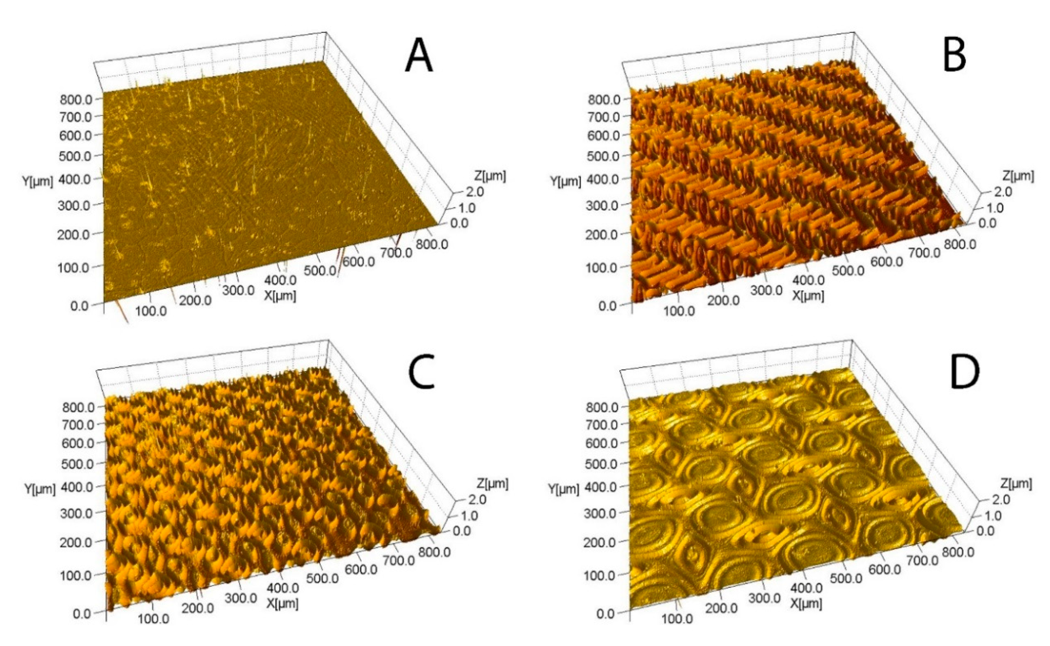
3.1. Coatings Overview

A summary of the structural, compositional, and optical properties of the titania coatings studied is given in Table 2. As expected for masked depositions, the thickness of the micro-patterned coatings was considerably lower, compared to that of the non-masked coating. Increasing the aperture of the stainless steel mask applied resulted in increasing coating thickness. Thus, sample TiO2-M26 was the thinnest one of the masked array, and TiO2-M149—the thickest one.
Energy-dispersive X-ray spectroscopy (EDX) was used for quantitative characterisation of film composition; with the composition of each coating analysed at four points to assess uniformity—the variation of the results was no greater than 2% for the same sample. No significant difference in composition of the films was observed with the EDX (data are given in Table 2); the composition of all studied samples was close to stoichiometric TiO2. Scanning electron microscopy was used for surface imaging of non-patterned and micro-patterned titania films; examples of the SEM images of each type of titania film are given in Figure 2. It is evident that the non-patterned sample was characterised with a relatively smooth surface, with no obvious defects. In contrast to that, the results of mask application can be clearly seen on the surface of the patterned samples (TiO2-M26 in the example given in Figure 2) in the form of regular micro-features. The shape and spacing of the features in all cases clearly resembled the aperture size and shape of the stainless steel mesh applied as a mask.
3D optical profilometry was used for further imaging and morphological characterisation of the titania films. Examples of the optical profilometry images are shown in Figure 3 and the values of the surface area calculated are given in Table 2. Clearly, application of the small aperture steel masks (samples TiO2-M26, TiO2-M58 and TiO2-M77) resulted in deposition of noticeably patterned films with much rougher surfaces, compared to the film deposited without masking. Compared to the rest of the micro-patterned array, sample TiO2-M149 looks visibly smoother, owing to the larger aperture size of the stainless steel mesh applied, as well as the associated higher percentage of open area. Surface area values were in good agreement with the visual comparison of the optical profilometry images, where sample TiO2-M26 was characterised with the highest surface area (ca. 10 times higher than non-patterned titania). The values of the surface area decreased with increasing mesh aperture size and can be presented in the following way: TiO2 ˂ TiO2-M149 ˂ TiO2-M77 ˂ TiO2-M58 ˂ TiO2-M26.

3.2. X-ray Diffraction (XRD) Results

The crystallographic properties of the patterned and non-patterned titanium dioxide coatings were identified by XRD. While, as expected for magnetron-sputtered titanium dioxide coatings, all samples were amorphous in the as-deposited state (XRD patterns of amorphous films did not exhibit any peaks, therefore are not given here), annealing in air at 873 K resulted in crystallinity development for all samples studied. The XRD patterns of the samples are presented in Figure 4. As is evident from the patterns, following the thermal treatment, all samples showed an anatase-only structure (identified with the crystallographic card 96-900-8215); characteristic anatase peaks were observed at 2θ angles of 25.3°, 36.9°, 37.8°, 38.5°, 48.0°, 53.8°, 55.1°, 62.6°, and 68.1°. No additional peaks besides those corresponding to the anatase titanium dioxide were seen on the XRD patterns of all annealed samples. The anatase (101) peak (2θ = 25.3°) was the most pronounced peak for all studied coatings, therefore the crystallite sizes were calculated from this peak using the Scherrer equation (Kα2 and instrumental broadening effects were removed prior to the calculation):
D = 0.89 × λ β × cos θ
where D is the crystallite size, λ is the CuKα wavelength (0.154 nm), β is the full width at half maximum intensity of the peak (in radians), and θ is the corresponding diffraction angle. The calculated crystallite sizes, as well as information on the crystallinity of the coatings are summarised in Table 2. As can be seen, no significant variation in either crystallite sizes or phase was observed as a result of patterning.

3.3. X-ray Photoelectron Spectroscopy (XPS) Results

Chemical states of the elements were analysed with XPS, using the Gaussian function for deconvolution of the individual peaks. Selected examples of the XPS results for patterned and non-patterned titania films are given in Figure 5. As expected, only Ti 2p, O 1s and C 1s peaks can be seen on the survey spectra of the coatings (Figure 5A,D), where the carbon peak is typically attributed to the presence of the adventitious carbon on the surface; the binding energies of the other elements were referenced to this peak at 284.8 eV.
High-resolution Ti 2p spectra of non-patterned and patterned films (shown in Figure 5B,E, respectively) had no significant variation, with two peaks clearly visible for all films studied. The earlier one at 458.3 eV corresponds to Ti 2p3/2, while the latter peak at 464.1 eV can be assigned to Ti 2p1/2; both observed peaks fit well with the positions of Ti in TiO2. The oxygen O 1s peak can be deconvoluted into two peaks at 529.6 and 531.5 eV, assigned to the lattice oxygen of TiO2 and O2 and/or H2O (–OH) on the surface of the TiO2 films, respectively. Increased intensity for the higher binding energy O 1s peak for the patterned films is possibly indicative of the higher water adsorption on the patterned films, compared to the one deposited without the use of a mesh.

3.4. Band Gap Calculation

UV-Vis transmittance spectra of the studied titania coatings were used for estimations of the band gap values. Optical band gaps of non-patterned and micro-patterned titania films were estimated using the Tauc plot method for semiconductor materials. Examples of the band gap calculation for non-patterned (TiO2) and patterned (TiO2-M26) films are shown in Figure 6; the values of the band gap for all studied coatings are listed in Table 2. It is evident that the application of the stainless steel mesh resulted in no significant variation in band gap values, compared to the non-patterned titania coating. The band gap values obtained were in good agreement with the phase information obtained from XRD, as the band gap value of anatase is typically reported as 3.20 eV [41].

3.5. Photocatalytic Activity Assessment

3.5.1. Methylene Blue Degradation Test

The methylene blue degradation test was employed as an initial assessment of the effect of micro-patterning on photocatalytic properties of the samples. Examples of the MB degradation kinetics are presented in Figure 7, while calculated values of the first-order rate constants of the degradation reaction are listed in Table 3. Though no striking improvement of photocatalytic activity can be seen as a result of micro-patterning, a clear trend can be observed in the methylene blue degradation tests: Samples deposited through a smaller aperture mesh are clearly more efficient than those deposited through the mesh with larger apertures, while the non-patterned TiO2 coating was the least efficient sample of the array.

3.5.2. Stearic Acid Degradation Test

Following the initial MB degradation results, the photocatalytic properties of micro-patterned and non-patterned titania coatings were further studied with a stearic acid degradation test. It is frequently reported that under UV irradiation the results of dye and stearic acid degradation tests follow the same trend [42,43]. Unlike dyes that are typically used for assessment of the water purification ability of the photocatalysts, stearic acid is typically used for assessment of the self-cleaning properties of photocatalytic films. Decomposition of the stearic acid was monitored through the disappearance of the characteristic IR peaks and generated plots of integrated area decay are presented in Figure 8. Additionally, reaction rate constants were calculated for quantitative representation of the degradation efficiency; the values are given in Table 3.
Data presented in Figure 8 and Table 3 clearly reveal that micro-patterned titania films, and sample TiO2-M26, in particular, were considerably more efficient, compared to non-patterned TiO2. Thus, for non-patterned titania, full disappearance of the stearic acid peaks was observed only after 48 h of UV irradiation, while for micro-patterned films this time varied from 16 h (for sample TiO2-M26) to 40 h (for sample TiO2-M149). It should be noted here that reaction rate constants were calculated in each case based on data points before full disappearance of the stearic acid IR peaks (e.g., for sample TiO2-M26 on 0 h, 8 h, and 16 h data points).

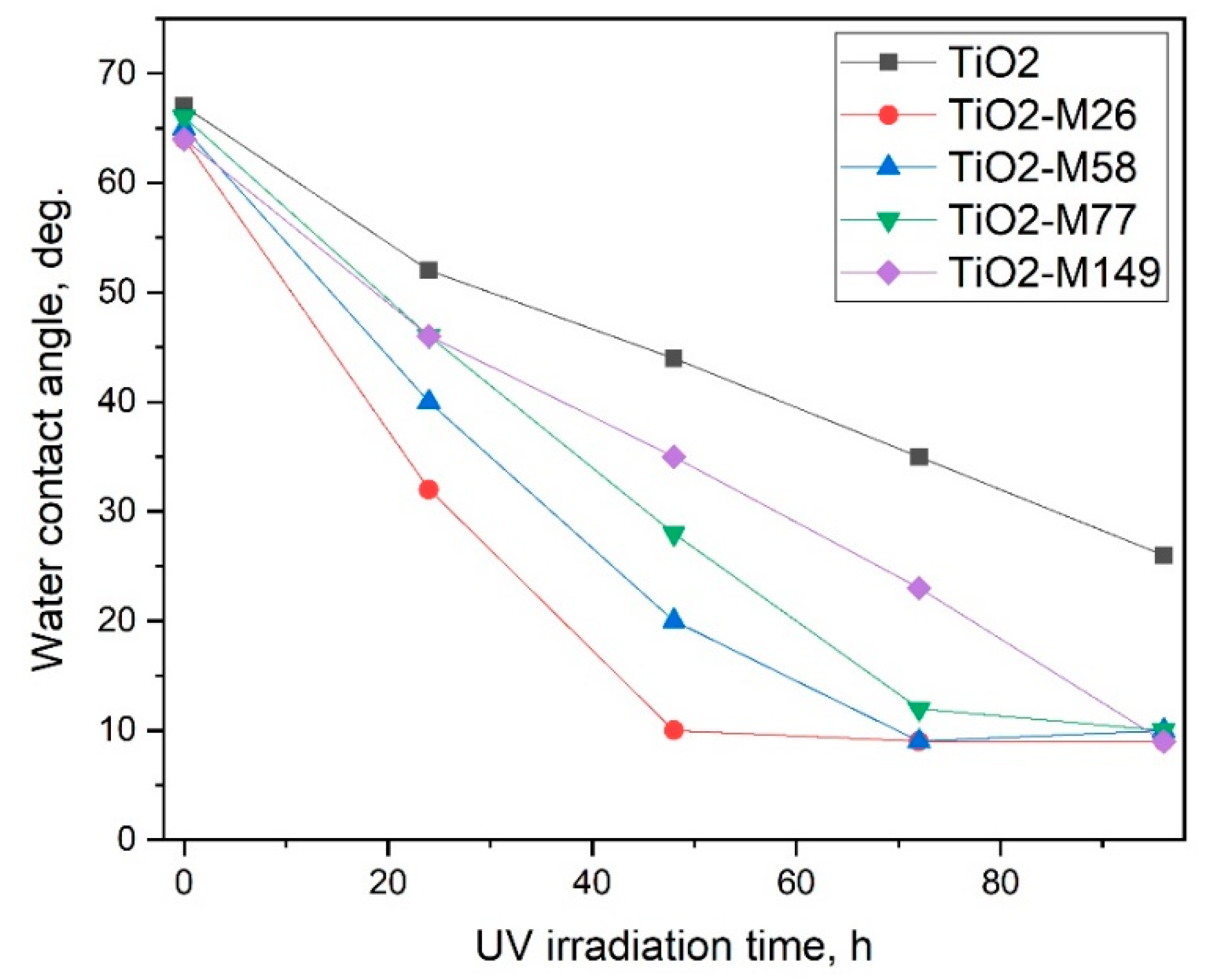
3.5.3. Oleic Acid Degradation Test

Results of the water contact angle measurements on oleic acid-coated titania coatings under UV light irradiation are plotted in Figure 9. For quantitative characterisation of the results here, we used ΔWCA (the difference between the water contact angle in the beginning of the experiment and after 96 h of UV irradiation) and the time required for the samples to achieve a superhydrophilic state (WCA ˂ 10°); both values are given in Table 3. Since, in the superhydrophilic state, the water droplet is spread on the surface in a very thin layer, no accurate measurements of WCA under 9° could be performed with the experimental equipment used. For this purpose, all datapoints after achieving superhydrophilicity are plotted as WCAs of 9°, while in reality, further reduction of WCA could be achieved. It is evident that the photocatalytic activity of the samples generally followed the same trend observed for the two earlier testing techniques, where sample TiO2-M26 was characterised with the highest photocatalytic activity, and non-patterned TiO2 sample—with the lowest one.

4. Discussion

The magnetron sputtering process is a well-known technique for the production of thin functional coatings, including photocatalytic titania films. Despite the number of advantages the process offers (precise composition control, high repeatability, and high durability of deposited coatings), there are also some factors limiting its application in photocatalysis. In particular, it is frequently reported that titanium dioxide coatings deposited under conventional sputtering conditions are smooth and densely packed [44,45], hence, surface area values are rather low.
It is a well-known fact that in photocatalysis, a higher surface area contributes to higher overall photoactivity. Consequently, a large body of effort in the development of thin film photocatalysts is aimed at finding simple yet scalable methods of surface area enlargement. Reportedly, photocatalytic materials with higher surface area provide not only higher areas of contact with the pollutant being degraded, but also higher number of active sites [46]. In the present work, we successfully increased the surface area of thin titania films through the application of stainless steel mesh masks in a one-step dry process. While being almost fully identical in nature (coatings were characterised with very close compositional properties, same crystal phase and crystal grain sizes and almost identical band gap values), the samples exhibited notably different results in the photocatalytic tests, which most likely arose as a function of the increased surface area of the films. The latter can be confirmed by the fact that the photocatalytic test results follow the same trend as the surface area values.
Though photocatalysis is typically described as a surface process, a number of authors highlight the influence of the coating thickness on the photocatalytic activity. Several studies proved the fact that coating photocatalytic activity increases with increasing thickness [47,48,49] until it reaches some critical value (usually reported as 300–400 nm), where further increase of the thickness does not affect the photocatalytic properties. While the initial improvement of photocatalytic activity with thickness is typically explained with the increased surface area of the thicker films, the latter phenomenon can be explained through the limited diffusion length of photogenerated charge carriers [49]. Application of the stainless steel mesh as masks unsurprisingly resulted in thinner films, compared to non-masked titania; however, the fact that the increase in surface area was so remarkable that the thinnest coating of the array (TiO2-M26) exhibited the highest photocatalytic activity is worth highlighting.
Every photocatalytic reaction involves several steps, namely transfer of the reactants to the surface of the photocatalyst, adsorption of the reactants, interfacial reactions on the surface of the photocatalyst, desorption of the reaction products, and transfer of the products away from the surface [46]. As highlighted in the text of BS ISO 27448:2009 (Test method for self-cleaning performance of semiconducting photocatalytic materials—Measurement of water contact angle), test results of the self-cleaning properties of photocatalytic samples are generally in good agreement with the results obtained via dye degradation tests [40]. Similarly, the results obtained by three different methods of assessment of photocatalytic activity of the micro-patterned films follow the same trend here, where the photocatalytic efficiency of the samples can be presented in the following way: TiO2 ˂ TiO2-M149 ˂ TiO2-M77 ˂ TiO2-M58 ˂ TiO2-M26.
However, it is evident that for the tests based on the direct contact of the pollutant with the surface of the photocatalyst (stearic and oleic acid degradation), the micro-patterned surfaces were clearly more efficient, compared to the non-patterned titania coating. While for the methylene blue degradation test, photocatalytic activity followed the same trend, the improvement in activity for the patterned surfaces was not quite as striking. We suggest that the observed phenomenon can be explained by the fact that for both stearic and oleic degradation tests the pollutant is in direct contact with the photocatalyst surface, while in the MB degradation test a transfer step is required. Therefore, the increase of surface area resulted in higher efficiency most notably for the testing methods where no transfer step is required.
Summarising the above observations, since the best improvement of the photocatalytic activity in this case was achieved for the tests where the model pollutant was in direct contact with the photocatalyst surface, rather than for the liquid phase one, we suggest that the proposed method may find a better practical application in self-cleaning surfaces, rather than, e.g., water treatment materials. It should be noted that the present work only presents early results, and precise optimisation of the deposition parameters, including the optimum mesh aperture, optimum thickness of the coating, etc., is the subject of a follow-up stage of work currently in progress.

5. Conclusions

In summary, we proposed a simple, yet efficient, method of photocatalytic thin film surface area enhancement. The surface area of titanium dioxide thin films was enhanced by the application of fine stainless steel meshes over the glass substrate; each mesh acted as a mask resulting in deposition of photocatalytic coatings with considerably higher surface areas, compared to the counterpart deposited without use of a mesh. Four grades of mesh with different aperture sizes were used, ranging from 0.026 to 0.149 mm. The deposited titania coatings were post-deposition annealed in air at 873 K for 30 min to promote crystallinity development. Coatings deposited without/using different grades of mesh were of different thicknesses, otherwise they were almost fully identical in terms of compositional, phase, and optical properties. The photocatalytic activity of coatings was tested under UV light using three different testing methods; namely methylene blue, stearic acid, and oleic acid degradation.
The results of the tests revealed that all micro-patterned films were more active than non-patterned titania, however the trend was more pronounced for stearic and oleic acid degradation tests. The latter phenomenon is likely to be attributed to the direct contact of photocatalyst surface with the model pollutant. We believe that the findings of the study and the proposed method, as well as follow-up work aimed at optimisation of the above findings, are of interest for those working on enhancement of the photocatalytic activity of self-cleaning surfaces.

Author Contributions

Conceptualization, M.R.; methodology, M.R.; software, D.S.; validation, M.R., formal analysis, M.R.; investigation, M.R.; resources, P.J.K.; data curation, M.R.; writing—original draft preparation, M.R.; writing—review and editing, P.J.K.; visualization, M.R.; supervision, P.J.K.; project administration, M.R.; funding acquisition, P.J.K. All authors have read and agreed to the published version of the manuscript.

Funding

This research received no external funding.

Conflicts of Interest

The authors declare no conflict of interest.

References

  1. Malato, S.; Fernández-Ibáñez, P.; Maldonado, M.I.; Blanco, J.; Gernjak, W. Decontamination and disinfection of water by solar photocatalysis: Recent overview and trends. Catal. Today 2009, 147, 1–59. [Google Scholar] [CrossRef]
  2. Pelaez, M.; Nolan, N.T.; Pillai, S.C.; Seery, M.K.; Falaras, P.; Kontos, A.G.; Dunlop, P.S.M.; Hamilton, J.W.J.; Byrne, J.A.; O’Shea, K.; et al. A review on the visible light active titanium dioxide photocatalysts for environmental applications. Appl. Catal. B: Environ. 2012, 125, 331–349. [Google Scholar] [CrossRef] [Green Version]
  3. Khataee, A.R.; Fathinia, M. Chapter 11—Recent Advances in Photocatalytic Processes by Nanomaterials. In New and Future Developments in Catalysis; Suib, S.L., Ed.; Elsevier: Amsterdam, The Netherlands, 2013; pp. 267–288. [Google Scholar] [CrossRef]
  4. Chen, J.; Poon, C.-S. Photocatalytic construction and building materials: From fundamentals to applications. Build. Environ. 2009, 44, 1899–1906. [Google Scholar] [CrossRef]
  5. Hernandez-Alonso, M.D.; Fresno, F.; Suarez, S.; Coronado, J.M. Development of alternative photocatalysts to TiO2: Challenges and opportunities. Energy Environ. Sci. 2009, 2, 1231–1257. [Google Scholar] [CrossRef]
  6. Fujishima, A.; Zhang, X. Titanium dioxide photocatalysis: Present situation and future approaches. Comptes Rendus Chim. 2006, 9, 750–760. [Google Scholar] [CrossRef]
  7. Spasiano, D.; Marotta, R.; Malato, S.; Fernandez-Ibañez, P.; Di Somma, I. Solar photocatalysis: Materials, reactors, some commercial, and pre-industrialized applications. A comprehensive approach. Appl. Catal. B: Environ. 2015, 170–171, 90–123. [Google Scholar] [CrossRef]
  8. ECHA proposes classification of TiO2 as category 2 carcinogen. Addit. Polym. 2017, 2017, 9–10. [CrossRef]
  9. Wang, Y.; He, Y.; Lai, Q.; Fan, M. Review of the progress in preparing nano TiO2: An important environmental engineering material. J. Environ. Sci. 2014, 26, 2139–2177. [Google Scholar] [CrossRef]
  10. Curcio, M.S.; Oliveira, M.P.; Waldman, W.R.; Sánchez, B.; Canela, M.C. TiO2 sol-gel for formaldehyde photodegradation using polymeric support: Photocatalysis efficiency versus material stability. Environ. Sci. Pollut. Res. 2015, 22, 800–809. [Google Scholar] [CrossRef]
  11. Nam, S.H.; Cho, S.J.; Jung, C.K.; Boo, J.H.; Sicha, J.; Herman, D.; Musil, J.; Vlcek, J. Comparison of hydrophilic properties of TiO2 thin films prepared by sol-gel method and reactive magnetron sputtering system. Thin Solid Film. 2011, 519, 6944–6950. [Google Scholar] [CrossRef]
  12. Zhou, W.; Du, G.; Hu, P.; Li, G.; Wang, D.; Liu, H.; Wang, J.; Boughton, R.I.; Liu, D.; Jiang, H. Nanoheterostructures on TiO2 nanobelts achieved by acid hydrothermal method with enhanced photocatalytic and gas sensitive performance. J. Mater. Chem. 2011, 21, 7937–7945. [Google Scholar] [CrossRef]
  13. Yang, D.; Liu, H.; Zheng, Z.; Yuan, Y.; Zhao, J.-C.; Waclawik, E.R.; Ke, X.; Zhu, H. An efficient photocatalyst structure: TiO2(B) nanofibers with a shell of anatase nanocrystals. J. Am. Chem. Soc. 2009, 131, 17885–17893. [Google Scholar] [CrossRef] [PubMed]
  14. Karches, M.; Morstein, M.; Rudolf von Rohr, P.; Pozzo, R.L.; Giombi, J.L.; Baltanás, M.A. Plasma-CVD-coated glass beads as photocatalyst for water decontamination. Catal. Today 2002, 72, 267–279. [Google Scholar] [CrossRef]
  15. Dunnill, C.W.H.; Aiken, Z.A.; Pratten, J.; Wilson, M.; Morgan, D.J.; Parkin, I.P. Enhanced photocatalytic activity under visible light in N-doped TiO2 thin films produced by APCVD preparations using t-butylamine as a nitrogen source and their potential for antibacterial films. J. Photochem. Photobiol. A: Chem. 2009, 207, 244–253. [Google Scholar] [CrossRef]
  16. Kelly, P.J.; West, G.T.; Ratova, M.; Fisher, L.; Ostovarpour, S.; Verran, J. Structural formation and photocatalytic activity of magnetron sputtered titania and doped-titania coatings. Molecules 2014, 19, 16327–16348. [Google Scholar] [CrossRef]
  17. Ratova, M.; Kelly, P.J.; West, G.T.; Iordanova, I. Enhanced properties of magnetron sputtered photocatalytic coatings via transition metal doping. Surf. Coat. Technol. 2013, 228 (Suppl. 1), S544–S549. [Google Scholar] [CrossRef]
  18. Marcelino, R.B.P.; Amorim, C.C.; Ratova, M.; Delfour-Peyrethon, B.; Kelly, P. Novel and versatile TiO2 thin films on PET for photocatalytic removal of contaminants of emerging concern from water. Chem. Eng. J. 2019, 370, 1251–1261. [Google Scholar] [CrossRef]
  19. Boukrouh, S.; Bensaha, R.; Bourgeois, S.; Finot, E.; de Lucas, M.C.M. Reactive direct current magnetron sputtered TiO2 thin films with amorphous to crystalline structures. Thin Solid Film. 2008, 516, 6353–6358. [Google Scholar] [CrossRef]
  20. Daviosdottir, S.; Shabadi, R.; Galca, A.C.; Andersen, I.H.I.; Dirscherl, K.; Ambat, R. Investigation of DC magnetron-sputtered TiO2 coatings: Effect of coating thickness, structure, and morphology on photocatalytic activity. Appl. Surf. Sci. 2014, 313, 677–686. [Google Scholar] [CrossRef] [Green Version]
  21. Tavares, C.J.; Vieira, J.; Rebouta, L.; Hungerford, G.; Coutinho, P.; Teixeira, V.; Carneiro, J.O.; Fernandes, A.J. Reactive sputtering deposition of photocatalytic TiO2 thin films on glass substrates. Mater. Sci. Eng. B-Solid State Mater. Adv. Technol. 2007, 138, 139–143. [Google Scholar] [CrossRef]
  22. Kelly, P.J.; Arnell, R.D. Magnetron sputtering: A review of recent developments and applications. Vacuum 2000, 56, 159–172. [Google Scholar] [CrossRef]
  23. Takeda, S.; Suzuki, S.; Odaka, H.; Hosono, H. Photocatalytic TiO2 thin film deposited onto glass by DC magnetron sputtering. Thin Solid Film. 2001, 392, 338–344. [Google Scholar] [CrossRef]
  24. Letcher, T.M.; Scott, J.L. Materials for a Sustainable Future; RSC Publishing: Cambridge, UK, 2012. [Google Scholar]
  25. Lin, Z.A.; Lu, W.C.; Wu, C.Y.; Chang, K.S. Facile fabrication and tuning of TiO2 nanoarchitectured morphology using magnetron sputtering and its applications to photocatalysis. Ceram. Int. 2014, 40, 15523–15529. [Google Scholar] [CrossRef]
  26. Wu, M.-C.; Chih, J.-S.; Huang, W.-K. Bismuth doping effect on TiO2 nanofibres for morphological change and photocatalytic performance. CrystEngComm 2014, 16, 10692–10699. [Google Scholar] [CrossRef]
  27. Zhang, X.; Jin, M.; Liu, Z.; Tryk, D.A.; Nishimoto, S.; Murakami, T.; Fujishima, A. Superhydrophobic TiO2 surfaces:  Preparation, photocatalytic wettability conversion, and superhydrophobic−superhydrophilic patterning. J. Phys. Chem. C 2007, 111, 14521–14529. [Google Scholar] [CrossRef]
  28. Pyun, M.W.; Kim, E.J.; Yoo, D.-H.; Hahn, S.H. Oblique angle deposition of TiO2 thin films prepared by electron-beam evaporation. Appl. Surf. Sci. 2010, 257, 1149–1153. [Google Scholar] [CrossRef]
  29. He, Y.P.; Zhang, Z.Y.; Zhao, Y.P. Optical and photocatalytic properties of oblique angle deposited TiO2 nanorod array. J. Vac. Sci. Technol. B Microelectron. Nanometer Struct. Process. Meas. Phenom. 2008, 26, 1350–1358. [Google Scholar] [CrossRef]
  30. Shang, J.; Li, W.; Zhu, Y. Structure and photocatalytic characteristics of TiO2 film photocatalyst coated on stainless steel webnet. J. Mol. Catal. A: Chem. 2003, 202, 187–195. [Google Scholar] [CrossRef]
  31. Atobe, M.; Yotsuya, S. Mask Vapor Deposition Method, Mask Vapor Deposition System, Mask, Process for Manufacturing, Mask, Apparatus for Manufacturing Display Panel, Display Panel and Electronic Device. U.S. Patent 20040142108A1, 22 July 2004. [Google Scholar]
  32. Nichols, R.; Mosier, J. Sputter Deposition Masking and Methods. U.S. Patent 20050006223A1, 13 January 2005. [Google Scholar]
  33. Demeter, A.; Tiron, V.; Lupu, N.; Stoian, G.; Sirghi, L. Plasma sputtering depositions with colloidal masks for fabrication of nanostructured surfaces with enhanced photocatalytic activity. Nanotechnology 2017, 28, 255302. [Google Scholar] [CrossRef]
  34. Paz, Y. Self-assembled monolayers and titanium dioxide: From surface patterning to potential applications. Beilstein J. Nanotechnol. 2011, 2, 845–861. [Google Scholar] [CrossRef] [Green Version]
  35. Yang, P.; Yang, M.; Zou, S.; Xie, J.; Yang, W. Positive and negative TiO2 micropatterns on organic polymer substrates. J. Am. Chem. Soc. 2007, 129, 1541–1552. [Google Scholar] [CrossRef] [PubMed]
  36. Klaysri, R.; Ratova, M.; Praserthdam, P.; Kelly, P. Deposition of visible light-active C-doped titania films via magnetron sputtering using CO2 as a source of carbon. Nanomaterials 2017, 7, 113. [Google Scholar] [CrossRef] [PubMed] [Green Version]
  37. Tauc, J.; Grigorovici, R.; Vancu, A. Optical properties and electronic structure of amorphous germanium. Phys. Status Solidi B 1966, 15, 627–637. [Google Scholar] [CrossRef]
  38. Ratova, M.; West, G.T.; Kelly, P.J.; Xia, X.; Gao, Y. Synergistic effect of doping with nitrogen and molybdenum on the photocatalytic properties of thin titania films. Vacuum 2015, 114, 205–212. [Google Scholar] [CrossRef]
  39. Ratova, M.; Klaysri, R.; Praserthdam, P.; Kelly, P.J. Visible light active photocatalytic C-doped titanium dioxide films deposited via reactive pulsed DC magnetron co-sputtering: Properties and photocatalytic activity. Vacuum 2018, 149, 214–224. [Google Scholar] [CrossRef]
  40. ISO27448 Fine Ceramics (Advanced Ceramics, Advanced Technical Ceramics)—Test Method for Self-Cleaning Performance of Semiconducting Photocatalytic Materials—Measurement of Water Contact Angle; ISO: Geneva, Switzerland, 2009.
  41. Schneider, J.; Matsuoka, M.; Takeuchi, M.; Zhang, J.; Horiuchi, Y.; Anpo, M.; Bahnemann, D.W. Understanding TiO2 photocatalysis: Mechanisms and materials. Chem. Rev. 2014, 114, 9919–9986. [Google Scholar] [CrossRef]
  42. Evans, P.; Mantke, S.; Mills, A.; Robinson, A.; Sheel, D.W. A comparative study of three techniques for determining photocatalytic activity. J. Photochem. Photobiol. A Chem. 2007, 188, 387–391. [Google Scholar] [CrossRef]
  43. Mills, A.; McFarlane, M. Current and possible future methods of assessing the activities of photocatalyst films. Catal. Today 2007, 129, 22–28. [Google Scholar] [CrossRef]
  44. Farahani, N.; Kelly, P.J.; West, G.; Ratova, M.; Hill, C.; Vishnyakov, V. Photocatalytic activity of reactively sputtered and directly sputtered titania coatings. Thin Solid Film. 2011, 520, 1464–1469. [Google Scholar] [CrossRef]
  45. Ratova, M.; West, G.; Kelly, P. Optimization studies of photocatalytic tungsten-doped titania coatings deposited by reactive magnetron co-sputtering. Coatings 2013, 3, 194–207. [Google Scholar] [CrossRef]
  46. Friedmann, D.; Mendive, C.; Bahnemann, D. TiO2 for water treatment: Parameters affecting the kinetics and mechanisms of photocatalysis. Appl. Catal. B: Environ. 2010, 99, 398–406. [Google Scholar] [CrossRef]
  47. Eufinger, K.; Poelman, D.; Poelman, H.; De Gryse, R.; Marin, G.B. Photocatalytic activity of dc magnetron sputter deposited amorphous TiO2 thin films. Appl. Surf. Sci. 2007, 254, 148–152. [Google Scholar] [CrossRef]
  48. Wu, C.-Y.; Lee, Y.-L.; Lo, Y.-S.; Lin, C.-J.; Wu, C.-H. Thickness-dependent photocatalytic performance of nanocrystalline TiO2 thin films prepared by sol–gel spin coating. Appl. Surf. Sci. 2013, 280, 737–744. [Google Scholar] [CrossRef]
  49. Xu, Y.; Xu, W.; Huang, F.; Wei, Q. Preparation and photocatalytic activity of TiO2-deposited fabrics. Int. J. Photoenergy 2012, 2012. [Google Scholar] [CrossRef] [Green Version]
Figure 1. Schematic representation of substrate arrangement.
Coatings 10 00068 g001
Figure 2. Examples of scanning electron microscopy (SEM) images of titania coatings: (A) non-patterned coating (Sample TiO2); (B) micro-patterned coating deposited through mesh with aperture 0.026 mm (Sample TiO2-M26).
Coatings 10 00068 g002
Figure 3. Examples of optical profilometry images: (A) sample TiO2, (B) sample TiO2-M26, (C) sample TiO2-M58, (D) sample TiO2-M149.
Coatings 10 00068 g003
Figure 4. X-ray diffraction (XRD) patterns of non-patterned and micro-patterned titanium dioxide samples.
Coatings 10 00068 g004
Figure 5. Selected X-ray photoelectron spectroscopy (XPS) results: (A) survey spectrum of sample TiO2; (B) Ti 2p spectrum of sample TiO2; (C) O 1s spectrum of sample TiO2; (D) survey spectrum of sample TiO2-M26; (E) Ti 2p spectrum of sample TiO2-M26; (F) O 1s spectrum of sample TiO2-M26.
Coatings 10 00068 g005
Figure 6. Examples of band gap calculation for samples TiO2 (non-patterned film) and TiO2-M26 (micro-patterned film).
Coatings 10 00068 g006
Figure 7. MB degradation kinetics under UV light in contact with non-patterned and micro-patterned titania coatings.
Coatings 10 00068 g007
Figure 8. Plots of the integrated area changes of the Fourier transform infrared spectroscopy (FTIR) spectra of the stearic acid peaks (3000–2700 cm−1) under UV light irradiation for non-patterned and micro-patterned titania coatings.
Coatings 10 00068 g008
Figure 9. Results of water contact angle measurements under UV light irradiation for non-patterned and micro-patterned titania coatings.
Coatings 10 00068 g009
Table 1. Parameters of the stainless steel mesh used for production of patterned titania coatings.
Sample IDStainless Steel Aperture, mmStainless Steel Wire Diameter, mmStainless Steel Mesh Open Area, %
TiO2
TiO2-M260.0260.02537
TiO2-M580.0580.03638
TiO2-M770.0770.05037
TiO2-M1490.1490.06349
Table 2. Summary of structural, compositional, and optical properties of the samples.
Sample IDCoating Thickness, nmComposition, at.% Ti/at.% OSurface Area S3a, µm2Crystal PhaseCrystallite Size, nmBand Gap, eV
TiO260034.6/65.4141.83Anatase14.63.20
TiO2-M2618035.2/64.81361.23Anatase14.73.21
TiO2-M5824032.9/67.1779.51Anatase14.63.21
TiO2-M7728034.7/65.3740.93Anatase14.53.20
TiO2-M14948035.0/65.0419.67Anatase14.63.20
Table 3. Results of photocatalytic tests (methylene blue (MB), stearic acid, and oleic acid degradation) for micro-patterned and non-patterned titania coatings.
Sample IDMB Degradation First Order Constant,
ka × 10−5, s−1
MB Removal After 1 h, %Stearic acid Degradation First Order Constant, ka, A cm−1 h−1Oleic Acid Degradation,ΔWCA, °OA Degradation-Time to Superhydrophilic State, h (WCA ˂ 10°)
TiO21.396.30.06941n/a
TiO2-M262.4011.40.2065548
TiO2-M581.9110.20.1425572
TiO2-M771.719.50.1045696
TiO2-M1491.477.20.0875596

