Metal Slot Color Filter Based on Thin Air Slots on Silver Block Array


Abstract
:1. Introduction
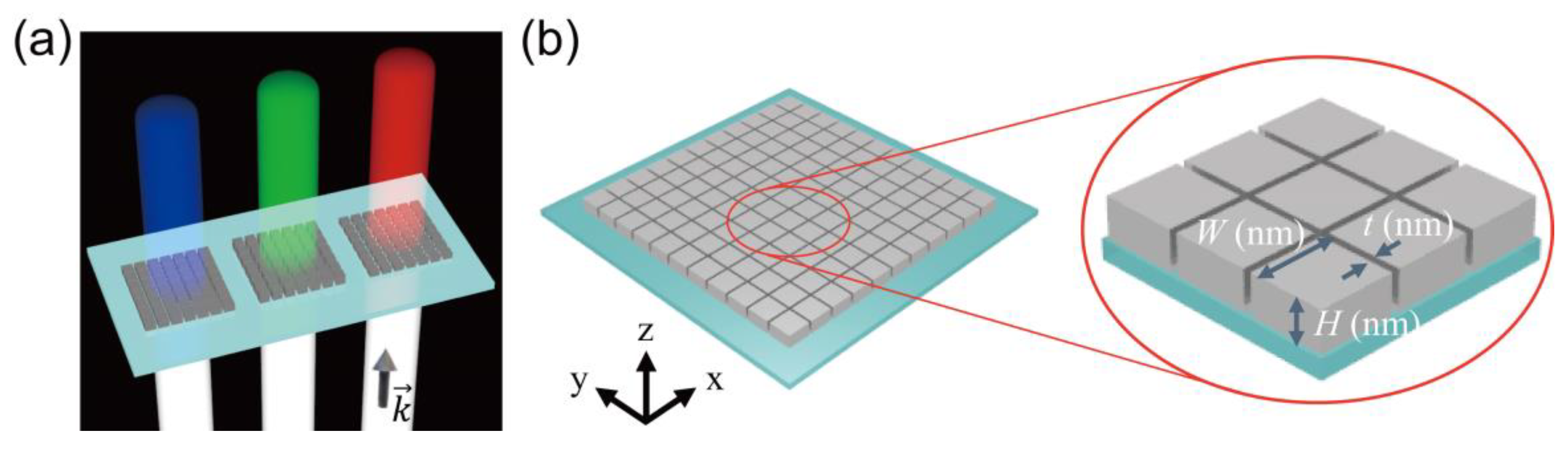
2. Structure Design
3. Optimized Structure and Color Space
4. Angular Distribution of Transmitted Light
5. Conclusions
Author Contributions
Funding
Conflicts of Interest
References
- Painter, O. Two-dimensional photonic band-gap defect mode laser. Science 1999, 284, 1819–1821. [Google Scholar] [CrossRef] [PubMed]
- Park, H.-G.; Kim, S.-H.; Seo, M.-K.; Ju, Y.-G.; Kim, S.-B.; Lee, Y.-H. Characteristics of electrically driven two-dimensional photonic crystal lasers. IEEE J. Quantum Electron. 2005, 41, 1131–1141. [Google Scholar] [CrossRef]
- Park, H.-G.; Kim, S.-H.; Kwon, S.-H.; Ju, Y.-G.; Yang, J.-K.; Baek, J.-H.; Kim, S.-B.; Lee, Y.-H. Electrically driven single-cell photonic crystal laser. Science 2004, 305, 1444–1447. [Google Scholar] [CrossRef] [PubMed]
- Lee, Y.J.; Lee, T.-W.; Lee, D.E.; Hong, S.; Kwon, S.-H. Spatially relocatable and spectrally tunable photonic crystal cavity by using a microsphere. J. Nanophotonics 2016, 10, 030501. [Google Scholar] [CrossRef]
- Fafarman, A.T.; Hong, S.H.; Caglayan, H.; Ye, X.; Diroll, B.T.; Paik, T.; Engheta, N.; Murray, C.B.; Kagan, C.R. Chemically tailored dielectric-to-metal transition for the design of metamaterials from nanoimprinted colloidal nanocrystals. Nano Lett. 2013, 13, 350c357. [Google Scholar] [CrossRef]
- Barnes, W.L.; Dereux, A.; Ebbesen, T.W. Surface plasmon subwavelength optics. Nature 2003, 424, 824–830. [Google Scholar] [CrossRef] [PubMed]
- Hong, S.; Lee, Y.J.; Moon, K.; Kwon, S.-H. Double resonance perfect absorption in a dielectric nanoparticle array. Curr. Opt. Photonics 2017, 1, 228–232. [Google Scholar]
- Wu, Y.-K.R.; Hollowell, A.E.; Zhang, C.; Guo, L.J. Angle-insensitive structural colours based on metallic nanocavities and coloured pixels beyond the diffraction limit. Sci. Rep. 2013, 3, 1194. [Google Scholar] [CrossRef]
- Wood, T.; Naffouti, M.; Berthelot, J.; David, T.; Claude, J.B.; Métayer, L.; Delobbe, A.; Favre, L.; Ronda, A.; Berbezier, I.; et al. All-dielectric color filters using sige-based mie resonator arrays. ACS Photonics 2017, 4, 873–883. [Google Scholar] [CrossRef]
- Proust, J.; Bedu, F.; Gallas, B.; Ozerov, I.; Bonod, N. All-dielectric colored metasurfaces with silicon mie resonators. ACS Nano 2016, 10, 7761–7767. [Google Scholar] [CrossRef]
- Yokogawa, S.; Burgos, S.P.; Atwater, H.A. Plasmonic color filters for CMOS image sensor applications. Nano Lett. 2012, 12, 4349–4354. [Google Scholar] [CrossRef] [PubMed]
- Li, Z.; Clark, A.W.; Cooper, J.M. Dual color plasmonic pixels create a polarization controlled nano color palette. ACS Nano 2016, 10, 492–498. [Google Scholar] [CrossRef] [PubMed]
- Arbabi, A.; Horie, Y.; Ball, A.J.; Bagheri, M.; Faraon, A. Subwavelength-thick lenses with high numerical apertures and large efficiency based on high-contrast transmitarrays. Nat. Commun. 2015, 6, 7069. [Google Scholar] [CrossRef] [PubMed]
- Ni, X.; Ishii, S.; Kildishev, A.V.; Shalaev, V.M. Ultra-thin, planar, Babinet-inverted plasmonic metalenses. Light. Appl. 2013, 2, e72. [Google Scholar] [CrossRef]
- Aieta, F.; Genevet, P.; Kats, M.A.; Yu, N.; Blanchard, R.; Gahurro, Z.; Capasso, F. Aberration-free ultrathin flat lenses and axicons at telecom wavelengths based on plasmonic metasurfaces. NANO Lett. 2012, 12, 4932–4936. [Google Scholar] [CrossRef] [PubMed]
- Kim, T.-H.; Cho, K.-S.; Lee, E.K.; Lee, S.J.; Chae, J.; Kim, J.W.; Kim, D.H.; Kwon, J.-Y.; Amaratunga, G.; Lee, S.Y.; et al. Full-colour quantum dot displays fabricated by transfer printing. Nat. Photonics 2011, 5, 176–182. [Google Scholar] [CrossRef]
- Forrest, S.R.; Burrows, P.E.; Shen, Z.; Gu, G.; Bulovic, V.; Thompson, M.E. The stacked OLED (SOLED): A new type of organic device for achieving high-resolution full-color displays. Synth. Met. 1997, 91, 9–13. [Google Scholar] [CrossRef]
- Miyamichi, A.; Ono, A.; Kamehama, H.; Kagawa, K.; Yasutomi, K.; Kawahito, S. Multi-band plasmonic color filters for visible-to-near-infrared image sensors. Opt. Express 2018, 26, 25178–25187. [Google Scholar] [CrossRef]
- Fleischman, D.; Fountaine, K.T.; Bukowsky, C.R.; Tagliabue, G.; Sweatlock, L.A.; Atwater, H.A. High spectral resolution plasmonic color filters with subwavelength dimensions. ACS Photonics 2019, 6, 332–338. [Google Scholar] [CrossRef]
- Xu, Q.; Almeida, V.R.; Panepucci, R.R.; Lipson, M. Experimental demonstration of guiding and confining light in nanometer-size low-refractive-index material. Opt. Lett. 2004, 29, 1626. [Google Scholar] [CrossRef]
- Veronis, G.; Fan, S. Modes of subwavelength plasmonic slot waveguides. J. Light. Technol. 2007, 25, 2511–2521. [Google Scholar] [CrossRef]
- Davoyan, A.R.; Shadrivov, I.V.; Kivshar, Y.S. Nonlinear plasmonic slot waveguides. Opt. Express 2008, 16, 21209. [Google Scholar] [CrossRef] [PubMed]
- Feng, N.-N.; Brongersma, M.L.; Dal Negro, L. Metal–dielectric slot-waveguide structures for the propagation of surface plasmon polaritons at 1.55 $\mu{\hbox {m}}$. IEEE J. Quantum Electron. 2007, 43, 479–485. [Google Scholar] [CrossRef]
- Lu, Z.; Zhao, W. Nanoscale electro-optic modulators based on graphene-slot waveguides. J. Opt. Soc. Am. B 2012, 29, 1490. [Google Scholar] [CrossRef]
- Choi, J.-H.; No, Y.-S.; So, J.-P.; Lee, J.M.; Kim, K.-H.; Hwang, M.-S.; Kwon, S.-H.; Park, H.-G. A high-resolution strain-gauge nanolaser. Nat. Commun. 2016, 7. [Google Scholar] [CrossRef] [PubMed]
- Kim, S.K.; Zhang, X.; Hill, D.J.; Song, K.D.; Park, J.S.; Park, H.G.; Cahoon, J.F. Doubling absorption in nanowire solar cells with dielectric shell optical antennas. Nano Lett. 2015, 15, 753–758. [Google Scholar] [CrossRef] [PubMed]
- Dusanowski, Ł.; Kwon, S.H.; Schneider, C.; Höfling, S. Near-Unity Indistinguishability Single Photon Source for Large-Scale Integrated Quantum Optics. Phys. Rev. Lett. 2019, 122, 1–6. [Google Scholar] [CrossRef] [PubMed]
- Iff, O.; Lundt, N.; Betzold, S.; Tripathi, L.N.; Emmerling, M.; Lee, Y.J.; Kwon, S.-H.; Höfling, S.; Schneider, C. Deterministic coupling of quantum emitters in WSe$_2$ monolayers to plasmonic nanocavities. Opt. Express 2018, 26, 25944–25951. [Google Scholar] [CrossRef]
- Malitson, I.H. Interspecimen comparison of the refractive index of fused silica. J. Opt. Soc. Am. 1965, 55, 1205. [Google Scholar] [CrossRef]
- Huang, K.C.Y.; Seo, M.K.; Sarmiento, T.; Huo, Y.; Harris, J.S.; Brongersma, M.L. Electrically driven subwavelength optical nanocircuits. Nat. Photonics 2014, 8, 244–249. [Google Scholar] [CrossRef]
- López-Tejeira, F.; Rodrigo, S.G.; Martín-Moreno, L.; García-Vidal, F.J.; Devaux, E.; Ebbesen, T.W.; Krenn, J.R.; Radko, I.P.; Bozhevolnyi, S.I.; González, M.U.; et al. Efficient unidirectional nanoslit couplers for surface plasmons. Nat. Phys. 2007, 3, 324–328. [Google Scholar] [CrossRef] [Green Version]
- Henzie, J.; Andrews, S.C.; Ling, X.Y.; Li, Z.; Yang, P. Oriented assembly of polyhedral plasmonic nanoparticle clusters. Proc. Natl. Acad. Sci. USA 2013, 110, 6640–6645. [Google Scholar] [CrossRef] [PubMed] [Green Version]
- Nakagawa, Y.; Kageyama, H.; Oaki, Y.; Imai, H. Direction control of oriented self-assembly for 1D, 2D, and 3D microarrays of anisotropic rectangular nanoblocks. J. Am. Chem. Soc. 2014, 136, 3716–3719. [Google Scholar] [CrossRef] [PubMed]
- Lee, T.-W.; Lee, D.E.; Lee, Y.J.; Kwon, S.-H. Low cross-talk, deep subwavelength plasmonic metal/insulator/metal waveguide intersections with broadband tunability. Photonics Res. 2016, 4, 272. [Google Scholar] [CrossRef]
- Miyazaki, H.T.; Kurokawa, Y. Squeezing visible light waves into a 3-nm-thick and 55-nm-long plasmon cavity. Phys. Rev. Lett. 2006, 96, 1–4. [Google Scholar] [CrossRef] [PubMed]
- Moon, K.; Lee, T.-W.; Lee, Y.; Kwon, S.-H. A Metal-insulator-metal deep subwavelength cavity based on cutoff frequency modulation. Appl. Sci. 2017, 7, 86. [Google Scholar] [CrossRef]
- Chen, Z.; Li, P.; Zhang, S.; Chen, Y.; Liu, P.; Duan, H. Enhanced extraordinary optical transmission and refractive-index sensing sensitivity in tapered plasmonic nanohole arrays. Nanotechnology 2019, 30, 335201. [Google Scholar] [CrossRef]
- Parashar, P.K.; Komarala, V.K. Engineered optical properties of silver-aluminum alloy nanoparticles embedded in SiON matrix for maximizing light confinement in plasmonic silicon solar cells. Sci. Rep. 2017, 7, 1–9. [Google Scholar] [CrossRef]
- Gerard, D.; Gray, S.K. Aluminium plasmonics. J. Phys. D Appl. Phys. 2015, 48. [Google Scholar] [CrossRef]


© 2019 by the authors. Licensee MDPI, Basel, Switzerland. This article is an open access article distributed under the terms and conditions of the Creative Commons Attribution (CC BY) license (http://creativecommons.org/licenses/by/4.0/).
Share and Cite
Kim, Y.; Moon, K.; Lee, Y.J.; Hong, S.; Kwon, S.-H. Metal Slot Color Filter Based on Thin Air Slots on Silver Block Array. Nanomaterials 2019, 9, 912. https://doi.org/10.3390/nano9060912
Kim Y, Moon K, Lee YJ, Hong S, Kwon S-H. Metal Slot Color Filter Based on Thin Air Slots on Silver Block Array. Nanomaterials. 2019; 9(6):912. https://doi.org/10.3390/nano9060912
Chicago/Turabian StyleKim, Youngsoo, Kihwan Moon, Young Jin Lee, Seokhyeon Hong, and Soon-Hong Kwon. 2019. "Metal Slot Color Filter Based on Thin Air Slots on Silver Block Array" Nanomaterials 9, no. 6: 912. https://doi.org/10.3390/nano9060912