Article

Short-Chain Modified SiO2 with High Absorption of Organic PCM for Thermal Protection

1
Guangdong Provincial Key Laboratory of Emergency Test for Dangerous Chemicals, Guangdong Institute of Analysis, Guangzhou 510070, China
2
The Engineering Research Center of None-Food Biomass Efficient Pyrolysis and Utilization Technology of Guangdong Higher Education Institutes, Dongguan University of Technology, Dongguan 523808, China
3
Guangdong Provincial Key Laboratory of Distributed Energy Systems, School of Chemical Engineering and Energy Technology, Dongguan University of Technology, Dongguan 523808, China
*
Author to whom correspondence should be addressed.
Nanomaterials 2019, 9(4), 657; https://doi.org/10.3390/nano9040657
Submission received: 2 April 2019 / Revised: 18 April 2019 / Accepted: 19 April 2019 / Published: 25 April 2019
(This article belongs to the Special Issue Thermal Transport in Nanostructures and Nanomaterials)

Abstract

:
Organic phase change materials (PCMs) have great potential in thermal protection applications but they suffer from high volumetric change and easy leakage, which require “leak-proof” packaging materials with low thermal conductivity. Herein, we successfully modify SiO2 through a simple 2-step method consisting of n-hexane activation followed by short-chain alkane silanization. The modified SiO2 (M-SiO2) exhibits superior hydrophobic property while maintaining the intrinsic high porosity of SiO2. The surface modification significantly improves the absorption rate of RT60 in SiO2 by 38%. The M-SiO2/RT60 composite shows high latent heat of 180 J·g−1, low thermal conductivity of 0.178 W·m−1·K−1, and great heat capacity behavior in a high-power thermal circuit with low penetrated heating flow. Our results provide a simple approach for preparing hydrophobic SiO2 with high absorption of organic PCM for thermal protection applications.

1. Introduction

Phase change materials (PCMs), a kind of materials with significant amounts of enthalpy through their phase transformations from liquid to solid [1,2], have attracted attention for their application in the thermal protection [3,4], energy storage [5,6,7], thermoregulation [8,9] and energy saving [10]. In thermal protection, the PCMs usually work as heat capacitors since they could absorb heating/cooling thermal energy in the thermal circuit to protect the back-end equipment/materials from thermal runaway/overcooling. Among different PCMs, organic PCMs possess the merits of good chemical stability, low supercooling, high latent heat, and they are generally non-toxic [11]. They have been widely used in thermal packaging industry to maintain temperature sensitive products within the required temperature range during their transfer [12]. However, the application of organic PCMs in thermal protection is largely hindered by the high volumetric change and easy leakage at the liquid state [13]. Therefore, providing “leak-proof” packaging is one of the biggest challenges for the application of organic PCM in thermal protection.
Various packaging materials have been tested to encapsulate organic PCM to form phase change composites. Prepolymers such as Melamine-formaldehyde (MF) resin [14,15], urea-formaldehyde (UF) resin [16], poly(urea−urethane) (PU) resin [17,18], gelatin and Arabic gum [19], and polymethylmethacrylate (PMMA) [20] can encase the organic PCMs via sol-gel, electrostatic spinning and microfluidics methods. These phase change composites usually turn into micro/nano encapsulations or phase change fibers. However, they suffer low phase change enthalpy, complex preparation process, and high cost. The other way is to use porous materials to absorb the organic PCMs by capillary force and surface tension. Porous carbon-based materials such as expanded graphite [21,22], graphene form [23,24], carbon nanotube sponge [25,26,27,28] could encase organic PCMs, but the high conductivity of carbon-based materials makes them unfavorable for thermal protection application. Moreover, carbon materials like graphene form, carbon nanotube sponge are currently too expansive for industrial application. Porous oxide materials such as bentonite [29], diatomite [30], and expanded perlite [31] can absorb PCMs to form phase change composite with low thermal conductivity, but these phase change composites are seriously restricted by their poor absorption of organic PCMs.
Silica (SiO2) aerogel, a scaffold ultralight material with high pore volume, large surface area, low thermal conductivity and high thermal stability, is a promising material for encapsulating organic PCMs [32,33] for thermal protection applications. However, the SiO2 aerogel is hydrophilic with hydroxyl on the surface, whereas organic PCMs are long chain alkane with hydrophobic property [34]. This incompatibility significantly restricts the mass fraction of organic PCMs in the SiO2 aerogel. Efforts have been paid to modify the SiO2 surface to be hydrophobic by inducing organic groups. Specifically, amine/methyltrimethoxysilane and methyltrimethoxysilane-dimethyldimethoxysilane modifications have been reported to effectively change the hydrophilicity of SiO2 [35,36,37]. However, the long carbon chains of the induced organic groups inevitably result in significant narrowing of the pore size of SiO2 aerogel, and consequently a decrease in absorption capacity of organic PCMs [38,39,40]. Therefore, developing hydrophobic SiO2 with high porosity is the crucial task ahead for applying SiO2 as an encapsulating material for organic PCMs composite. Actually, Rao et al. have demonstrated the possibility of using short-chain -Si-(CH3)3 modification to prepare hydrophobic SiO2, but the 8-step synthesis is rather complicated, and they did not investigate its application for organic PCM absorption [41]. Nevertheless, this inspires us to consider short-chain modified SiO2 as organic PCM packing material. Short-chain -Si-(CH3)3 occupies less space itself, and thus short-chain modification is expected to retain more porosity of SiO2 compared to the long-chain modification mentioned above. Therefore, our efforts have been applied to simplify the 8-step synthesis of hydrophobic SiO2 developed by Rao et al., evaluate its absorption capacity of organic PCM, and promote its application for thermal protection.
In this work, a simple 2-step method was used to prepare hydrophobic SiO2. N-hexane was found to effectively activate the surface of SiO2, which further benefits the replacement of hydroxy with short-chain silicane via hexamethyl disilazane silanization. The short-chain modified SiO2 (M-SiO2) exhibits excellent hydrophobic property while maintaining the intrinsic high porosity of SiO2. The M-SiO2 shows much-improved absorption of RT60 (a typical organic PCM) than SiO2. Compared to SiO2-based composite, the M-SiO2-based phase change composite shows improved thermal protection behavior and greater latent heat. Moreover, the M-SiO2-based phase change composite shows good reversible stability and no leakage of PCMs was observed after 200 heating-cooling cycles. The M-SiO2 aerogel-based phase change composite could rectify the large ambient heat flow and exhibits great potential for thermal protection applications.

2. Materials and Methods

2.1. Materials

The hydrophilic SiO2 aerogel and technical grade paraffin RT60 (melting point Tm = 60 °C) were purchased from Guangzhou GBS Technology Co, Ltd, Guangzhou, China. and Hangzhou ruhr energy science and technology Co, Ltd, Hangzhou, China, respectively. Hexamethyl disilazane and n-hexane were provided by Aladdin Co, Ltd, Shanghai, China.

2.2. Preparation of M-SiO2 Aerogel and RT60/M-SiO2 Composite

The M-SiO2 aerogel was synthesized by the method reported previously with minor modification [41], as shown in Figure 1. First, 20 g of hydrophilic SiO2 aerogel was dried at 80 °C for 12 h, then poured into the 200 mL of n-hexane to activate the surface of SiO2 aerogel. After ultrasonic dispersion at 50 °C for 1 h, the activated SiO2 aerogel was centrifuged from the suspension and immersed into the 200 mL Hexamethyl disilazane for 48 h to replace the hydroxy with silicane and release ammonia at room temperature. Last, the modified SiO2 aerogel was centrifuged and dried under vacuum at 50 °C for 5 h. The hydrophobic SiO2 aerogel was obtained and defined as modified SiO2 aerogel (M-SiO2 aerogel). For comparison, Hexamethyl disilazane silanized SiO2 without n-hexane activation was also prepared and defined as unactivated modified SiO2 (unactivated M-SiO2). The PCM composite was prepared through the infiltrating method. 80 g of RT60 was kept in a thermal chamber at 80 °C until it completely melted. Then 20 g of M-SiO2 aerogel was added into the liquid RT60 to encapsulate the melting RT60. After stirring at 80 °C for 2 h, the RT60/M-SiO2 aerogel was fabricated.

2.3. Characterization of M-SiO2 Aerogel and RT60/M-SiO2 Aerogel

The morphology and microstructure of SiO2 aerogel and M-SiO2 aerogel were observed by a field emission scanning electron microscopy (SEM SU8020, Hitachi, Tokyo, Japan). The water contact angle of the SiO2 aerogel and M-SiO2 aerogel were observed by a water contact angle meter (SDC 500, Dongguan Chengding Technology Co. Ltd, Dongguan, China.). The SiO2 aerogel and M-SiO2 aerogel were compressed into blocks, then pure water was dropped onto the surface of SiO2 aerogel and M-SiO2 aerogel blocks. The microscopic pores of SiO2 aerogel and M-SiO2 aerogel were observed by a transmission electron microscopy (FEI Tecnai G20, Hillsboro, OR, USA). The structure of the phase change material was characterized by FT-IR spectra and XRD. The FT-IR spectra were recorded on a Bruker 550 from 400–4000 cm−1 using KBr pellets. The XRD pattern was scanned from 10–70° with intervals of 0.2°. The phase change temperature and latent heat of SiO2 aerogel and M-SiO2 aerogel-based phase change materials were measured using a differential scanning calorimeter (Q200, TA). For DSC measurements, 5–8 mg of each sample was sealed in an aluminum pan. The heating rate is 10 °C·min−1 and the N2 flow rate was 50 mL·min−1. The thermal stability of SiO2 aerogel and M-SiO2 aerogel-based phase change composite was investigated by the thermogravimetric analysis (TGA) using a thermal analyzer (Q600 SDT, TA, URT100, New Castle, PA, USA). The measurements were conducted by heating the samples from room temperature to 600 °C at a heating rate of 10 °C·min−1 under N2 atmosphere with a flow rate of 100 mL·min−1. The thermal conductivity of SiO2 aerogel and M-SiO2 aerogel-based phase change composite was measured using a thermal constants analyzer (Hot Disk TPS 2500 S, Hot Disk AB, Gothenburg, Sweden). The thermal insulation performance of SiO2 aerogel and M-SiO2 aerogel-based phase change material was conducted in a double layer cubic box. The SiO2 aerogel and M-SiO2 aerogel-based phase change material was placed in the inner face of the box. The box was heated to 65 °C and placed in a cool stage at 20 °C. Then, the temperature of the inner box was measured by thermocouples. For comparison, the XPS foam was also used as thermal insulation material, and the synergistic effect of XPS foam, SiO2 aerogel and M-SiO2 aerogel-based phase change composite was also investigated. The temperature data was recorded by Agilent 34970A, Agilent Technologies Inc, Santa Clara, CA, USA.

3. Results and Discussion

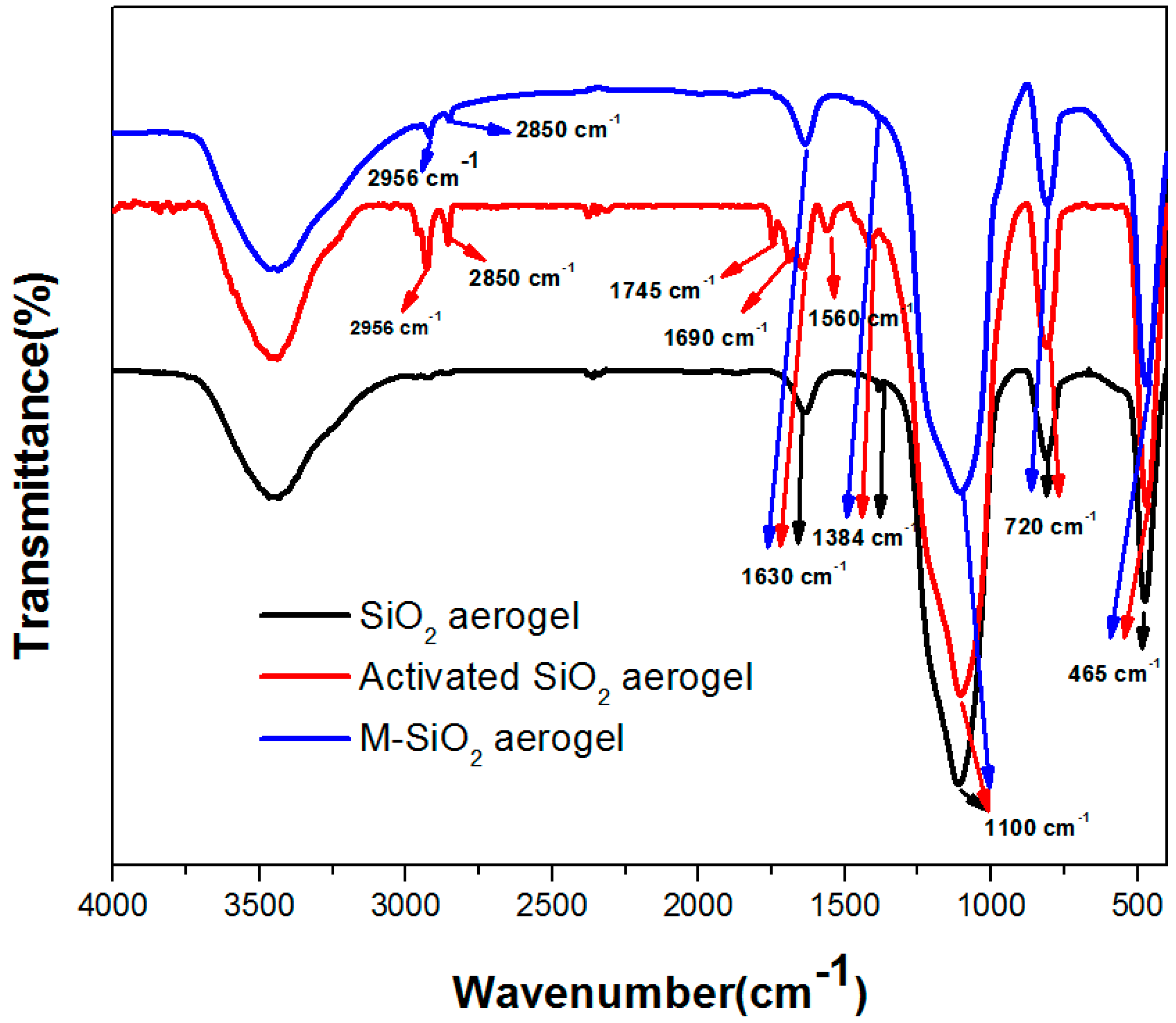
3.1. FT-IR Investigation of SiO2, Activated SiO2 and M-SiO2 Aerogels

To analyze the structures of SiO2 aerogel and M-SiO2 aerogel-based PCM, the FT-IR analysis was conducted. The FT-IR spectra of SiO2 aerogel, activated SiO2 aerogel, and M-SiO2 aerogel are displayed in Figure 2. The low intensity bands at 3000–3700 cm−1 and around 1630 cm−1 are assigned to -OH stretching vibrations [42], the peaks at 1100, 788, and 465 cm−1 are ascribed to the bending vibration of Si-O-Si. The activated SiO2 aerogel shows two absorptive peaks at 2956 cm−1 and 2850 cm−1, which correspond to the stretching vibration of -CH3 and -CH2-. In addition, the activated SiO2 show peaks at 1745 cm−1 and 1690 cm−1, which could be assigned to the C=O stretching vibration [43], yet the mechanism of the C=O formation in the activated SiO2 is not clear. The band at 1560 cm−1 can be attributed to the stretching vibration of C=C [44]. The M-SiO2 aerogel shows two weak absorptive peaks at 2956 cm−1 and 2850 cm−1, verifying the successful surface modification. The FT-IR spectrum of other samples can be found in Figure S1. Specifically, in RT60, the peaks at 2956 cm−1 and 2850 cm−1 correspond to the stretching vibration of -CH3 and -CH2-, the peaks at around 1465 cm−1 belong to the deformation vibration of -CH2 and -CH3, and the peak at 1415 cm−1, 1384 cm−1 and 720 cm−1 are due to the CH vibration [45], CH3 deformation [46] and in-plane rocking vibration of -CH2 respectively [19]. The spectrum of the RT60/SiO2 aerogel and RT60/M-SiO2 aerogel keeps all of the absorptive peaks of RT60, SiO2 aerogel or M-SiO2 aerogel, indicating that the combination of the RT60 and SiO2 aerogel or M-SiO2 aerogel is a physical process.

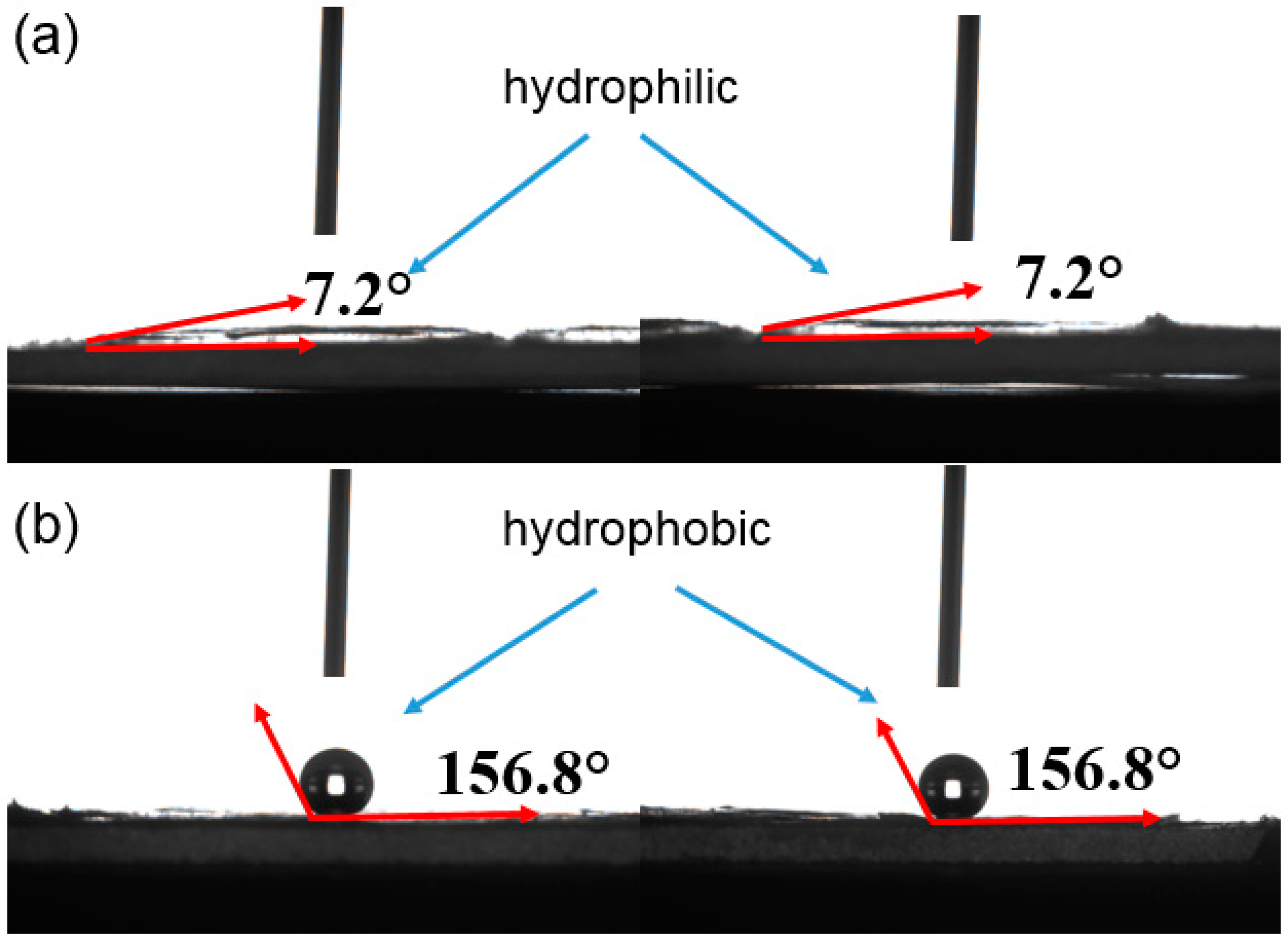
3.2. Wettability of SiO2 and M-SiO2 Aerogels

The water contact angle of the SiO2 aerogel and M-SiO2 aerogel is illustrated in Figure 3. The water contact angle of the SiO2 aerogel is 7.2° (Figure 3a), suggesting that the SiO2 aerogel is hydrophilic, which is caused by the surface group of –Si-OH. In contrast, Figure 3b shows that the water contact angle of M-SiO2 aerogel is 156.8°, indicating the successful hydrophobic modification. The obtained M-SiO2 aerogel is hydrophobic, which is consistent with previous reports, where the M-SiO2 aerogel was used as a super-hydrophobic layer for light transition systems [47].

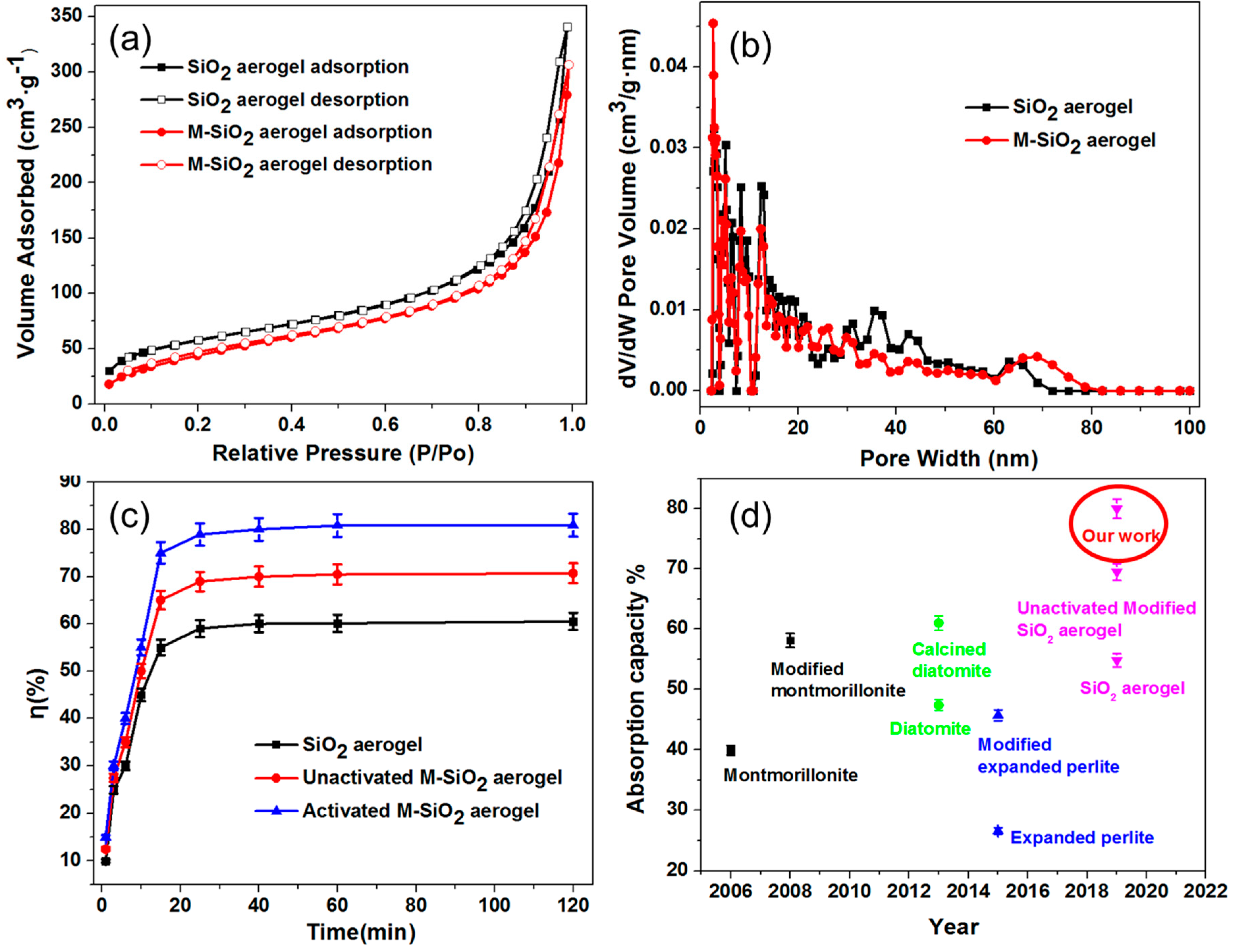
3.3. Porosity and Absorption Capacity of SiO2, Unactivated M-SiO2, and Activated M-SiO2 Aerogels

To evaluate the porosity of SiO2 and M-SiO2 aerogels, the N2 adsorption and desorption isotherms were measured. As shown in Figure 4a, the N2 adsorption/desorption curve shows a steep hysteresis loop [48], indicating the week connection between N2 and the SiO2 aerogel. This is because the mesoporous was built within SiO2 or M-SiO2 particles by Van der Waals’ force. The sharp rise at a relative pressure (P/P0) of ~0.9 indicates the existence of mesoporous with narrow pore size. The BET surface area (SBET) of SiO2 aerogel and M-SiO2 aerogel is 350 m2·g−1 and 306 m2·g−1, suggesting that the alkyl surface modification does not result in a significant decrease in surface area of the SiO2 aerogel. This is consistent with our hypothesis that the short chain -O-Si-(CH3)3 occupies less space compared to the long chain counterparts. Both SiO2 aerogel and M-SiO2 aerogel show wide range pore size distribution from 2–80 nm and most of them are in the range of 2–20 nm, as shown in Figure 4b. After modifying with -O-S-(CH3)3, the average pore size slightly decreases since the surface of the M-SiO2 aerogel is connected with-O-Si-(CH3)3.
Leakage test was carried out to evaluate the RT60 encapsulating capacity of SiO2 aerogel and M-SiO2 aerogel, as shown in Figure S2. The RT60/SiO2 aerogel and RT60/M-SiO2 aerogel powders were placed on the paper and heated at 90 °C for 2 h. After cooling down to room temperature, the appearance of the RT60/SiO2 and RT60/M-SiO2 composites on the paper was recorded. The RT60/SiO2 aerogel shows no leakage with RT60 mass fraction of 55% and 60%. When the mass fraction of RT60 increased to 65%, obvious leakage was observed. As a contrast, no leakage was observed for the RT60/M-SiO2 aerogel with RT60 mass fraction of 75% and 80%. As the mass fraction of RT60 increased to 85%, the RT60/M-SiO2 aerogel started to leak. Obviously, the M-SiO2 aerogel demonstrated higher RT60 absorption capacity than SiO2, and the RT60/M-SiO2 exhibited better thermal stability than the RT60/SiO2 even, at a higher loading of RT60.
Figure 4a illustrates the mass fraction of RT60 absorbed in the SiO2 aerogel, unactivated M-SiO2 aerogel and activated M-SiO2 aerogel with different adsorption time. The encapsulation ratio of RT60 in SiO2 aerogel and M-SiO2 aerogel was calculated from the DSC results (vide infra). For SiO2 aerogel, the mass fraction rapidly increased from 0 to 50% in 20 min, and gently increased from 50.0% to 55.1% from 20–40 min. Then, the RT60 tended to a stationary mass ratio of 57.9%, which was considered as the maximum adsorption ratio of the SiO2 aerogel. For unactivated M-SiO2 aerogel, the mass fraction of RT60 increased to 65% in 19 min and tended to a stationary mass ratio of 70.5%. For activated M-SiO2 aerogel, the mass fraction of RT60 increased from 0 to 72.8% in 18 min, and slightly increased from 72.8% to 76.8% from 18–30 min. Finally, the RT60 in RT60/activated M-SiO2 aerogel reached a stationary mass ratio up to 80.0%. Above all, the activated M-SiO2 aerogel showed larger absorption capacity of RT60 than SiO2 aerogel and unactivated M-SiO2 aerogel. For comparison, the absorption capacities of previously reported porous oxides were summarized in Figure 4d and Table S1. The state of art montmorillonite [49], diatomite [50], expanded perlite [51] and SiO2 aerogel [40] could absorb paraffin at a mass ratio of 39.9%, 47.4%, 26.6%, and 54.8%. When modified with organic groups, the absorption capacity of the aforementioned porous oxides increased to 58.1% [52], 61% [53], 45.7%, and 69.5%. Obviously, our M-SiO2 aerogel showed the highest absorption capacity of up to 80%. We note that, in general, the absorbability of porous materials decreases with the length of the carbon chain of paraffin [54]. Therefore, in principle, the organic PCM we choose (RT60) to test the absorption ability of our M-SiO2 should be more difficult to encapsulate since it has the longest carbon chain among all the paraffins summarized in Figure 4d and Table S1. Therefore, the high RT60 encapsulation capacity of our M-SiO2 highlights its outstanding absorbability. As mentioned previously, the short chain-O-Si-(CH3)3 occupy less space compared to the long chain counterparts, and therefore does not result in significant shrinking in pore size. This is also accompanied with an additional benefit, the M-SiO2 aerogel with the short chain does not block (or block less) the pores of the SiO2 aerogel. Therefore, the less obstructed infiltration path allows for easier RT60 siphoning and consequently a higher absorption rate.

3.4. Morphology of SiO2, M-SiO2 Aerogels and Their PCMs Composites

The morphology and microstructure of SiO2 aerogel and M-SiO2 aerogel are shown in Figure 5. The SiO2 aerogel was created by the second accumulation of SiO2 particles with diameters of ~10 nm, the SiO2 particle built mesoporous mountain range and the pores were typical scaffold with SiO2 particles [55], as shown in Figure 5a. After modification, the surface of the M-SiO2 aerogel turned hydrophobic as illustrated previously in Figure 3b. Obviously, the short chain modification did not result in a significant narrowing of the pore size of the SiO2 aerogel, the M-SiO2 aerogel largely maintained the secondary pores of the SiO2 aerogel, as shown in Figure 5b. After modifying the surface with alkyl, the surface tension of SiO2 aerogel also increased. TEM analysis was carried out to further investigate the microstructure of SiO2 aerogel and M-SiO2 aerogel, as shown in Figure 6a,d. It could be clearly seen that the SiO2 particles of SiO2 aerogel accumulate together with a high surface area. When modified with -Si-(CH3)3, the M-SiO2 aerogel was dispersed better than SiO2 aerogel, the number of accumulated SiO2 particles decreases largely, verifying the successful surface modification of the SiO2 aerogel, as shown in Figure 6b. The SiO2 aerogel and M-SiO2 aerogel were used to absorb the RT60, and the morphology and microstructure of RT60/SiO2 aerogel and RT60/M-SiO2 aerogel are shown in Figure 5c,d. When absorbing RT60 into the pores of SiO2 aerogel, each SiO2 particle was inflated by RT60 like tomatoes on sticks, as shown in Figure 5c. The pores of SiO2 aerogel were only partially filled with RT60, since the SiO2 aerogel was hydrophilic. For comparison, the narrow space of the M-SiO2 aerogel was almost completely filled by RT60, which was attributed to hydrophobic nature of both the M-SiO2 aerogel and RT60.

3.5. Thermal Properties of RT60/SiO2 and RT60/M-SiO2 Aerogels

The phase change temperatures and latent heats of RT60, RT60/SiO2 aerogel, and RT60/M-SiO2 aerogel were investigated. Figure 7a and Table S2 show the melting and freezing curves of RT60, RT60/SiO2 aerogel, and RT60/M-SiO2 aerogel. For the pure RT60, there was an endothermic peak in the melting DSC curve and an exothermic peak in the solidifying DSC curve. The melting and freezing temperatures were measured to be 57.98 and 56.61 °C for the pure RT60, 57.78 and 57.56 °C for RT60/SiO2 aerogel and 57.32 and 57.16 °C for RT60/M-SiO2 aerogel. The melting and freezing latent heats were measured to be 225.3 and 223.9 J·g−1 for the pure RT60, 130.5 and 129.4 J·g−1 for the pure RT60/SiO2 aerogel, and 180.2 and 178.9 J·g−1 for RT60/M-SiO2 aerogel. The phase change characteristics of the RT60/M-SiO2 aerogel were similar to those of the pure RT60, because there was no chemical reaction between RT60 and M-SiO2 aerogel in the preparation process. The encapsulation ratio (R) of RT60 by SiO2 aerogel and M-SiO2 aerogel was calculated from the DSC results using Equation (1).
R = Δ H m , C o m p o s i t e Δ H m , P a r a f f i n × 100 %
where ΔHm,Composite and ΔHm,Paraffin represent the melting latent heat of RT60/SiO2 aerogel, RT60/M-SiO2 aerogel and RT60, respectively. The encapsulation ratio (R) of paraffin in the RT60/SiO2 aerogel and RT60/M-SiO2 aerogel was calculated to be 57.9 and 80.0%, the encapsulation ratio of M-SiO2 aerogel increased by 38.1% as compared to SiO2 aerogel. The encapsulation ratio of M-SiO2 aerogel was also higher than other porous oxides such as bentonite [29], diatomite [30], and expanded perlite [31], which showed encapsulation ratio of paraffin lower than 60% as previously summarized in Table S1.
The thermal stability of RT60, RT60/SiO2 aerogel and RT60/M-SiO2 aerogel were tested by TGA and the weight loss as a function of temperature is depicted in Figure 7b and Figure S5. The RT60 started to evaporate at about 230 °C, and the final weight loss percentage was nearly 100% at 410 °C. For SiO2 aerogel and M-SiO2 aerogel, there was no obvious weight loss till 600 °C, as confirmed in Figure S5. The SiO2 aerogel showed slight weight lost from 100% to 97.5% as the temperature rises from room temperature to 600 °C, the M-SiO2 aerogel had a weight loss stage of 1.5% at about 100 °C, which was attributed to the evaporation of the short chain alkyl. In the TGA curve of the RT60/SiO2 aerogel, the composite started to lose weight at ~270 °C and the final weight loss percentage was nearly 40%. The weight percentage of the RT60 in RT60/SiO2 aerogel was ~60%. The RT60/M-SiO2 composite started to lose weight at ~270 °C and the final weight loss percentage was nearly 20%. The weight percentage of the RT60 in RT60/M-SiO2 aerogel was ~80%, which matches well with the calculation from the DSC results. The TGA results also suggested that the PCM composite could slightly enhance the thermal stability of the RT60.

3.6. Reversible Stability of RT60/SiO2 and RT60/M-SiO2 Aerogels

To investigate the reversible stability, the RT60/M-SiO2 aerogel was heated and cooled with different heating-cooling cycles. As shown in Figure 8a,b, no obvious change was found in the morphology and microstructure of RT60/SiO2 aerogel and RT60/M-SiO2 aerogel after 200 heating/cooling cycles, meaning that the RT60/SiO2 and RT60/M-SiO2 aerogels have great reversible stability. To further verify the stability of RT60/SiO2 aerogel and RT60/M-SiO2 aerogel, the melting and freezing enthalpy of RT60/SiO2 aerogel and RT60/M-SiO2 aerogel after every heating/cooling cycles were recorded. The melting enthalpy of RT60/SiO2 aerogel and RT60/M-SiO2 aerogel maintained at 130.5 and 180.2 J·g−1 from 1–200 heating/cooling cycles. The freezing enthalpy of RT60/SiO2 aerogel and RT60/M-SiO2 aerogel kept at 128.8 and 178.8 J·g−1 in the heating/cooling process. These results confirmed the excellent reversible stability of RT60/SiO2 and RT60/M-SiO2 aerogels.

3.7. Thermal Conductivity of RT60/SiO2 and RT60/M-SiO2 Aerogels

The thermal conductivity of RT60/SiO2 and RT60/M-SiO2 aerogel blocks were measured and the results are shown in Figure 9. The thermal conductivity of RT60/SiO2 aerogel block increased from 0.114 to 0.164 W·m−1·K−1 as the packing density increases from 600 to 1000 kg·m−3, while the thermal conductivity of RT60/M-SiO2 aerogel block increased from 0.132 to 0.174 W·m−1·K−1, as shown in Figure 9a. The thermal conductivity of RT60/SiO2 aerogel and RT60/M-SiO2 aerogel kept at ~0.164 W·m−1·K−1 and 0.174 W·m−1·K−1 as the temperature increase from room temperature to 70 °C, as shown in Figure 9b. For comparison, the thermal conductivity of RT60 was measured to be 0.23 W·m−1·K−1. Note that the RT60/SiO2 aerogel and RT60/M-SiO2 aerogel block showed lower thermal conductivity than RT60, which is due to the low thermal conductivity of SiO2 aerogel and M-SiO2 aerogel (0.026 W·m−1·K−1) [56].

3.8. Thermal Capacity Behavior of RT60/SiO2 and RT60/M-SiO2 Aerogels

To investigate the thermal capacity behavior of SiO2 and M-SiO2 aerogel-based PCMs, the SiO2 and M-SiO2 aerogel-based PCMs were compressed into a cuboid with packing density of 1000 kg·m−3, and the cuboid was placed inner the XPS (polystyrene) box, as shown in Figure 10a. To record the temperature of SiO2 aerogel and M-SiO2 aerogel-based PCMs, the thermocouples were placed in the center of the PCMs cuboid with a thickness of 2 cm, the relative error of temperature data is within ± 1%. For comparison, the thermal insulation property of the XPS form with a thickness of 2 cm was also tested, as shown in Figure 9b. The XPS form, SiO2 aerogel and M-SiO2 aerogel-based PCMs decorative box was placed in the thermal oven to be heated at 65 °C. Then the box was then placed at an ambient temperature of 20 °C to perform the cooling energy storage property. Figure 10b showed that the temperature of XPS form decreased quickly from 65 to 30 °C in 400 s, while the temperature of SiO2 aerogel kept at 60 °C for 4800 s. The temperature of M-SiO2 aerogel-based PCMs decreased quickly from 65 to 60 °C in 700 s, and leveled at 60 °C from 700 to 8000 s, then dropped from 60 to 30 °C in 3000 s. The SiO2 aerogel and M-SiO2 aerogel-based PCMs demonstrated much better thermal insulation property than XPS form. The M-SiO2 aerogel-based PCMs could keep the temperature at 60 °C 2500 s longer than SiO2 aerogel-based PCMs. This is due to the large enthalpy of M-SiO2 aerogel-based PCMs.
To quantitatively evaluate the thermal capacity of SiO2 aerogel and M-SiO2 aerogel-based PCMs, the rectified heat flow from ambient to the box was calculated by Equation (2):
q = λ T T 0 Δ x
where q is the apparent rectified heat flow (W·m−2), λ is the thermal conductivity(W·m−1·K−1), T is the temperature of PCMs side, T0 is the ambient temperature, Δx is the thickness of the PCMs.
The rectification of the heat flow by SiO2 aerogel and M-SiO2 aerogel-based PCMs is shown in Figure 10c. The rectified heat flow of XPS form was only 75 W·m−2 and dropped rapidly to 0 W·m−2 in 2000 s, while the rectified heat flow of the SiO2 aerogel and M-SiO2 aerogel-based PCM was as high as 245 W·m−2, which was much higher than that of the XPS form. This is because the PCMs could absorb a larger mass of the heat than the XPS form. The M-SiO2 aerogel-based PCMs could rectify the heat flow for a longer time than SiO2 aerogel-based PCMs since the M-SiO2 aerogel-based PCMs have larger enthalpy.
In thermal circuit systems, the thermal behavior could be analyzed by the equivalent circuit method [57,58]. The XPS form could restrict the heat flow in the thermal circuit, and the PCMs could rectify the high-power heat flow in the thermal circuit. For thermal protection, the rectified effect of the PCMs is much better than the restriction effect of the XPS form. The rectified heat flow of the M-SiO2 aerogel-based PCM was 226.7% higher than that of the XPS form. The rectified heat flow decreased with exposure time as the temperature difference became small. The XPS form-based box could be equivalent to a thermal resistance, while the PCMs could be regarded as a heat capacitor, as shown in Figure 10d. In the thermal flow circuit, the thermal resistance could reduce the heat flow from q0 to qR, while the PCMs could rectify large heat flow from q0 to qC. The M-SiO2 aerogel-based PCM has a large thermal capacity with excellent rectification capability of heat flow, which is promising in high heat power systems includes thermal insulation applications, such as medicine, transportation and hot food storage.

4. Conclusions

In this work, hydrophobic SiO2 aerogel was obtained by short chain alkyl modification through a simple 2 step method. The N-hexane activation followed by short-chain alkane silanization yielded hydrophobic M-SiO2. In contrast to conventional long-chain modification of SiO2, the short chain modification did not result in significant shrinking of the pore size. The M-SiO2 showed outstanding absorption capacity of RT60 at a mass ratio up to 80%, which is significantly higher than un-modified SiO2 (58%) and also other porous oxides. The phase change composite RT60/M-SiO2 aerogel showed a high phase change enthalpy of 180 J·g−1 and low thermal conductivity of 0.178 W·m−1·K−1. The RT60/M-SiO2 composite was able to rectify of cooling thermal energy of 245 W·m−2, and could be used as a thermal capacitor. Moreover, the RT60 and M-SiO2 exhibited great compatibility, and the thermal properties of the RT60/M-SiO2 composite could be well maintained after 200 heat/cooling cycles. The hydrophobic M-SiO2 shows great potential for encapsulating organic PCMs for thermal protection applications. Specifically, the RT60/M-SiO2 aerogel is well suited for thermal protection during hot food transfer.

Supplementary Materials

The following are available online at https://www.mdpi.com/2079-4991/9/4/657/s1, Figure S1: FT-IR spectrum of all samples, Figure S2: leakage test of RT60/SiO2 aerogel and RT60/M-SiO2 aerogel, Figure S3: XRD patterns of the SiO2 aerogel and M-SiO2 aerogel, Figure S4: XRD patterns of all samples, Figure S5: Weight loss of SiO2 aerogel and M-SiO2 aerogel, Figure S6: Melting and freezing behavior of RT60/SiO2 aerogel with different heating/cooling, Figure S7: Melting and freezing behavior of RT60/M-SiO2 aerogel with different heating/cooling cycle, Table S1: The absorption capacity of different supporting materials, Table S2: The melting and freezing behavior of SiO2 aerogel and M-SiO2 aerogel based PCM.

Author Contributions

F.W. and J.L. conceived the idea. S.G. performed the samples preparation, characterization and measurement of PCMs and wrote the manuscript. F.W., J.L., S.G., J.P. and X.L. discussed and analyzed the results. J.L. and F.W. revised the manuscript. J.L. and F.W. supervised the whole research work. All authors read and approved the final version of the manuscript.

Funding

This work was supported by Science and Technology Planning Project of Guangdong Province, China(2017A070702017), China Postdoctoral Science Foundation (No. 2018M640784), High-level Talents Project of Dongguan University of Technology (KCYKYQD2017017) and Research Start-up Funds of Dongguan University of Technology (GC300502-40).

Conflicts of Interest

The authors declare no conflict of interest.

References

  1. Choon, H.D.; Levinson, N.S.; Unyong, J.; Younan, X. Emerging applications of phase-change materials (pcms): Teaching an old dog new tricks. Angew. Chem. Int. Ed. 2014, 53, 3780–3795. [Google Scholar]
  2. Aftab, W.; Huang, X.; Wu, W.; Liang, Z.; Mahmood, A.; Zou, R. Nanoconfined phase change materials for thermal energy applications. Energy Environ. Sci. 2018, 11, 1392–1424. [Google Scholar] [CrossRef]
  3. Mccann, J.T.; Marquez, M.; Xia, Y. Melt coaxial electrospinning: A versatile method for the encapsulation of solid materials and fabrication of phase change nanofibers. Nano Lett. 2006, 6, 2868. [Google Scholar] [CrossRef] [PubMed]
  4. Qi, Z.; He, Z.; Fang, X.; Zhang, X.; Zhang, Z. Experimental and numerical investigations on a flexible paraffin/fiber composite phase change material for thermal therapy mask. Energy Storage Mater. 2017, 6, 36–45. [Google Scholar]
  5. Han, G.; Li, H.; Grossman, J.C. Optically-controlled long-term storage and release of thermal energy in phase-change materials. Nat. Commun. 2017, 8, 1446. [Google Scholar] [CrossRef] [Green Version]
  6. Zhitomirsky, D.; Grossman, J.C. Conformal electroplating of azobenzene-based solar thermal fuels onto large-area and fiber geometries. Acs Appl. Mater. Interfaces 2016, 8, 26319–26325. [Google Scholar] [CrossRef] [PubMed]
  7. Lu, X.; Huang, J.; Kang, B.; Yuan, T.; Qu, J.-P. Bio-based poly (lactic acid)/high-density polyethylene blends as shape-stabilized phase change material for thermal energy storage applications. Sol. Energy Mater. Sol. Cells 2019, 192, 170–178. [Google Scholar] [CrossRef]
  8. Hou, S.; Wang, M.; Guo, S.; Su, M. Photo-thermally driven refreshable microactuators based on graphene oxide doped paraffin. Acs Appl. Mater. Interfaces 2017, 9, 26476–26482. [Google Scholar] [CrossRef] [PubMed]
  9. Xue, J.; Zhu, C.; Li, J.; Li, H.; Xia, Y. Integration of phase-change materials with electrospun fibers for promoting neurite outgrowth under controlled release. Adv. Funct. Mater. 2018, 28, 1705563. [Google Scholar] [CrossRef]
  10. Ji, H.; Sellan, D.P.; Pettes, M.T.; Kong, X.; Ji, J.; Shi, L.; Ruoff, R.S. Enhanced thermal conductivity of phase change materials with ultrathin-graphite foams for thermal energy storage. Energy Environ. Sci. 2014, 7, 1185–1192. [Google Scholar] [CrossRef]
  11. Huang, X.; Liu, Z.; Xia, W.; Zou, R.; Han, R.S. Alkylated phase change composites for thermal energy storage based on surface-modified silica aerogels. J. Mater. Chem. A 2015, 3, 1935–1940. [Google Scholar] [CrossRef]
  12. Zalba, B.; Marın, J.M.; Cabeza, L.F.; Mehling, H. Review on thermal energy storage with phase change: Materials, heat transfer analysis and applications. Appl. Therm. Eng. 2003, 23, 251–283. [Google Scholar] [CrossRef]
  13. Liangjie, C.; Ruqiang, Z.; Wei, X.; Zhenpu, L.; Yuanyuan, S.; Jinlong, Z.; Yingxia, W.; Jianhua, L.; Dingguo, X.; Anyuan, C. Electro- and photodriven phase change composites based on wax-infiltrated carbon nanotube sponges. Acs Nano 2012, 6, 10884–10892. [Google Scholar]
  14. Chen, Z.; Wang, J.; Fei, Y.; Zhang, Z.; Gao, X. Preparation and properties of graphene oxide-modified poly(melamine-formaldehyde) microcapsules containing phase change material n-dodecanol for thermal energy storage. J. Mater. Chem. A 2015, 3, 11624–11630. [Google Scholar] [CrossRef]
  15. Zhang, H.; Wang, X. Fabrication and performances of microencapsulated phase change materials based on n -octadecane core and resorcinol-modified melamine–formaldehyde shell. Colloids Surf. A Physicochem. Eng. Asp. 2009, 332, 129–138. [Google Scholar] [CrossRef]
  16. Jian-Ping, W.; Xiao-Peng, Z.; Hui-Lin, G.; Qing, Z. Preparation of microcapsules containing two-phase core materials. Langmuir ACS J. Surf. Colloids 2004, 20, 10845. [Google Scholar]
  17. Yoo, Y.; Martinez, C.; Youngblood, J.P. Synthesis and characterization of microencapsulated phase change materials with poly(urea-urethane) shells containing cellulose nanocrystals. Acs Appl. Mater. Interfaces 2017, 9, 31763–31776. [Google Scholar] [CrossRef]
  18. Yoo, Y.; Martinez, C.; Youngblood, J.P. Sustained dye release using poly(urea-urethane)/cellulose nanocrystal composite microcapsules. Langmuir 2017, 33, 1521–1532. [Google Scholar] [CrossRef]
  19. Hawlader, M.N.A.; Uddin, M.S.; Khin, M.M. Microencapsulated pcm thermal-energy storage system. Appl. Energy 2003, 74, 195–202. [Google Scholar] [CrossRef]
  20. Alkan, C.; Sarı, A.; Karaipekli, A. Preparation, thermal properties and thermal reliability of microencapsulated -eicosane as novel phase change material for thermal energy storage. Energy Convers. Manag. 2011, 93, 143–147. [Google Scholar] [CrossRef]
  21. Sarı, A.; Karaipekli, A. Thermal conductivity and latent heat thermal energy storage characteristics of paraffin/expanded graphite composite as phase change material. Appl. Therm. Eng. 2007, 27, 1271–1277. [Google Scholar] [CrossRef]
  22. Zhang, Z.; Fang, X. Study on paraffin/expanded graphite composite phase change thermal energy storage material. Energy Convers. Manag. 2006, 47, 303–310. [Google Scholar] [CrossRef]
  23. Li, G.; Hong, G.; Dong, D.; Song, W.; Zhang, X. Multiresponsive graphene-aerogel-directed phase-change smart fibers. Adv. Mater. 2018, 30, e1801754. [Google Scholar] [CrossRef]
  24. Haiyan, S.; Zhen, X.; Chao, G. Multifunctional, ultra-flyweight, synergistically assembled carbon aerogels. Adv. Mater. 2013, 25, 2554–2560. [Google Scholar]
  25. Liu, Z.; Zou, R.; Lin, Z.; Gui, X.; Chen, R.; Lin, J.; Shang, Y.; Cao, A. Tailoring carbon nanotube density for modulating electro-to-heat conversion in phase change composites. Nano Lett. 2013, 13, 4028–4035. [Google Scholar] [CrossRef]
  26. Zhang, Q.; Liu, J. Sebacic acid/cnt sponge phase change material with excellent thermal conductivity and photo-thermal performance. Sol. Energy Mater. Sol. Cells 2017. [Google Scholar] [CrossRef]
  27. Chen, Y.; Zhang, Q.; Wen, X.; Yin, H.; Liu, J. A novel cnt encapsulated phase change material with enhanced thermal conductivity and photo-thermal conversion performance. Sol. Energy Mater. Sol. Cells 2018, 184, 82–90. [Google Scholar] [CrossRef]
  28. Zhang, Q.; Liu, J. Anisotropic thermal conductivity and photodriven phase change composite based on rt100 infiltrated carbon nanotube array. Sol. Energy Mater. Sol. Cells 2019, 190, 1–5. [Google Scholar] [CrossRef]
  29. Min, L.; Wu, Z.; Kao, H.; Tan, J. Experimental investigation of preparation and thermal performances of paraffin/bentonite composite phase change material. Energy Convers. Manag. 2011, 52, 3275–3281. [Google Scholar]
  30. Karaman, S.; Karaipekli, A.; Sarı, A.; Biçer, A. Polyethylene glycol (peg)/diatomite composite as a novel form-stable phase change material for thermal energy storage. Sol. Energy Mater. Sol. Cells 2011, 95, 1647–1653. [Google Scholar] [CrossRef]
  31. Karaipekli, A.; Sarı, A. Capric–myristic acid/expanded perlite composite as form-stable phase change material for latent heat thermal energy storage. Renew. Energy 2008, 33, 2599–2605. [Google Scholar] [CrossRef]
  32. Leventis, N.; Sotiriouleventis, C.; Guohui Zhang, A.; Rawashdeh, A.M.M. Nanoengineering strong silica aerogels. Nano Lett. 2002, 2, 957–960. [Google Scholar] [CrossRef]
  33. Kistler, S.S. The relation between heat conductivity and structure in silica aerogel. J. Phys. Chem 1935, 39, 79–85. [Google Scholar] [CrossRef]
  34. Xiangfa, Z.; Hanning, X.; Jian, F.; Changrui, Z.; Yonggang, J. Preparation, properties and thermal control applications of silica aerogel infiltrated with solid–liquid phase change materials. J. Exp. Nanosci. 2012, 7, 17–26. [Google Scholar] [CrossRef] [Green Version]
  35. Katti, A.; Shimpi, N.; Roy, S.; Lu, H.; Fabrizio, E.F.; Dass, A.; Capadona, L.A.; Leventis, N. Chemical, physical, and mechanical characterization of isocyanate cross-linked amine-modified silica aerogels. Chem. Mater. 2006, 18, 285–296. [Google Scholar] [CrossRef]
  36. Boday, D.J.; Stover, R.J.; Muriithi, B.; Keller, M.W.; Wertz, J.T.; Defriend Obrey, K.A.; Loy, D.A. Strong, low-density nanocomposites by chemical vapor deposition and polymerization of cyanoacrylates on aminated silica aerogels. Acs Appl. Mater. Interfaces 2009, 1, 1364–1369. [Google Scholar] [CrossRef]
  37. Malfait, W.J.; Zhao, S.; Verel, R.; Iswar, S.; Rentsch, D.; Fener, R.; Zhang, Y.; Milow, B.; Koebel, M.M. Surface chemistry of hydrophobic silica aerogels. Chem. Mater. 2015, 27, 6737–6745. [Google Scholar] [CrossRef]
  38. Daniel, E.; Bharat, B. Transparent, superhydrophobic, and wear-resistant coatings on glass and polymer substrates using sio2, zno, and ito nanoparticles. Langmuir ACS J. Surf. Colloids 2012, 28, 11391. [Google Scholar]
  39. Zhou, Y.; Han, S.T.; Xu, Z.X.; Yang, X.B.; Ng, H.P.; Huang, L.B.; Roy, V.A.L. Functional high-k nanocomposite dielectrics for flexible transistors and inverters with excellent mechanical properties. J. Mater. Chem. 2012, 22, 14246–14253. [Google Scholar] [CrossRef]
  40. Li, H.; Chen, H.; Li, X.; Sanjayan, J.G. Development of thermal energy storage composites and prevention of pcm leakage. Appl. Energy 2014, 135, 225–233. [Google Scholar] [CrossRef]
  41. Shewale, P.M.; Venkateswara Rao, A.; Parvathy Rao, A.; Bhagat, S.D. Synthesis of transparent silica aerogels with low density and better hydrophobicity by controlled sol–gel route and subsequent atmospheric pressure drying. J. Sol-Gel Sci. Technol. 2009, 49, 285–292. [Google Scholar] [CrossRef]
  42. Gaspar, H.; Andrade, M.; Pereira, C.; Pereira, A.; Rebelo, S.; Araújo, J.; Pires, J.; Carvalho, A.; Freire, C. Alkene epoxidation by manganese (iii) complexes immobilized onto nanostructured carbon cmk-3. Catal. Today 2013, 203, 103–110. [Google Scholar] [CrossRef]
  43. Babu, B.C.; Naresh, V.; Prakash, B.J.; Buddhudu, S. Structural, thermal and dielectric properties of lithium zinc silicate ceramic powders by sol-gel method. Ferroelectr. Lett. 2011, 38, 114–127. [Google Scholar] [CrossRef]
  44. Lopes, B.B.; Rangel, R.C.; Antonio, C.A.; Durrant, S.F.; Cruz, N.C.; Rangel, E.C. Mechanical and tribological properties of plasma deposited ac: H: Si: O films. In Nanoindentation in Materials Science; IntechOpen: Rijeka, Croatia, 2012. [Google Scholar]
  45. Smith, D.M.; Chughtai, A.R. The surface structure and reactivity of black carbon. Colloids Surf. A Physicochem. Eng. Asp. 1995, 105, 47–77. [Google Scholar] [CrossRef]
  46. Ruhai, T.; Oliver, S.; Meng, L.; Wenchuang Walter, H.; Chabal, Y.J.; Jinming, G. Infrared characterization of interfacial si-o bond formation on silanized flat sio2/si surfaces. Langmuir 2010, 26, 4563–4566. [Google Scholar]
  47. Budunoglu, H.; Yildirim, A.; Guler, M.O.; Bayindir, M. Highly transparent, flexible, and thermally stable superhydrophobic ormosil aerogel thin films. Acs Appl. Mater. Interfaces 2011, 3, 539. [Google Scholar] [CrossRef] [PubMed]
  48. Kleitz, F.; Choi, S.H.; Ryoo, R. Cubic ia3d large mesoporous silica: Synthesis and replication to platinum nanowires, carbon nanorods and carbon nanotubes. Chem. Commun. 2003, 9, 2136–2137. [Google Scholar] [CrossRef]
  49. Fang, X.; Zhang, Z. A novel montmorillonite-based composite phase change material and its applications in thermal storage building materials. Energy Build. 2006, 38, 377–380. [Google Scholar] [CrossRef]
  50. Xu, B.; Li, Z. Paraffin/diatomite composite phase change material incorporated cement-based composite for thermal energy storage. Appl. Energy 2013, 105, 229–237. [Google Scholar] [CrossRef]
  51. Ramakrishnan, S.; Sanjayan, J.; Wang, X.; Alam, M.; Wilson, J. A novel paraffin/expanded perlite composite phase change material for prevention of pcm leakage in cementitious composites. Appl. Energy 2015, 157, 85–94. [Google Scholar] [CrossRef]
  52. Fang, X.; Zhang, Z.; Chen, Z. Study on preparation of montmorillonite-based composite phase change materials and their applications in thermal storage building materials. Energy Convers. Manag. 2008, 49, 718–723. [Google Scholar] [CrossRef]
  53. Sun, Z.; Zhang, Y.; Zheng, S.; Park, Y.; Frost, R.L. Preparation and thermal energy storage properties of paraffin/calcined diatomite composites as form-stable phase change materials. Thermochim. Acta 2013, 558, 16–21. [Google Scholar] [CrossRef] [Green Version]
  54. Jeong, S.G.; Jeon, J.; Lee, J.H.; Kim, S. Optimal preparation of pcm/diatomite composites for enhancing thermal properties. Int. J. Heat Mass Transf. 2013, 62, 711–717. [Google Scholar] [CrossRef]
  55. Zu, G.; Shen, J.; Wang, W.; Zou, L.; Lian, Y.; Zhang, Z. Silica-titania composite aerogel photocatalysts by chemical liquid deposition of titania onto nanoporous silica scaffolds. Acs Appl. Mater. Interfaces 2015, 7, 5400–5409. [Google Scholar] [CrossRef] [PubMed]
  56. Domínguez-Muñoz, F.; Anderson, B.; Cejudo-López, J.M.; Carrillo-Andrés, A. Uncertainty in the thermal conductivity of insulation materials. Energy Build. 2010, 42, 2159–2168. [Google Scholar] [CrossRef] [Green Version]
  57. Dambrine, G.; Cappy, A.; Heliodore, F.; Playez, E. A new method for determining the fet small-signal equivalent circuit. IEEE Trans. Microw. Theory Tech. 2002, 36, 1151–1159. [Google Scholar] [CrossRef]
  58. Baena, J.D.; Bonache, J.; Martín, F.; Sillero, R.M.; Falcone, F.; Lopetegi, T.; Laso, M.A.G.; Garcia-Garcia, J.; Gil, I.; Portillo, M.F. Equivalent-circuit models for split-ring resonators and complementary split-ring resonators coupled to planar transmission lines. IEEE Trans. Microw. Theory Tech. 2005, 53, 1451–1461. [Google Scholar] [CrossRef]
Figure 1. Illustration of M-SiO2 aerogel and RT60/M-SiO2 aerogel preparations.
Nanomaterials 09 00657 g001
Figure 2. The FT-IR spectrum of SiO2, activated SiO2, and M-SiO2 aerogels.
Nanomaterials 09 00657 g002
Figure 3. Water contact angles of SiO2 aerogel (a) and M-SiO2 aerogel (b).
Nanomaterials 09 00657 g003
Figure 4. N2 adsorption/desorption isotherms of SiO2 and M-SiO2 aerogels (a), pore size distribution of SiO2 and M-SiO2 aerogels (b), and absorption capacities of SiO2 and M-SiO2 aerogels: Our results (c) and a summary of the recent studies (d) are shown.
Nanomaterials 09 00657 g004
Figure 5. SEM images of SiO2 aerogel (a) and M-SiO2 aerogel (b), SiO2 aerogel-based phase change materials (PCMs) (c) and M-SiO2 aerogel-based PCMs (d).
Nanomaterials 09 00657 g005
Figure 6. TEM images of SiO2 aerogel (a) and M-SiO2 aerogel (b).
Nanomaterials 09 00657 g006
Figure 7. DSC curves of RT60, RT60/SiO2, RT60/M-SiO2 aerogels at a heating rate of 10 °C·min−1 (a), thermal stability measurements of SiO2 aerogel, M-SiO2, RT60, RT60/SiO2, RT60/M-SiO2 aerogels at 10 °C·min−1 (b).
Nanomaterials 09 00657 g007
Figure 8. SEM image of RT60/SiO2 and RT60/M-SiO2 aerogels after 200 heating/cooling cycles (a,b). Absolute values of the melting and freezing enthalpy of RT60/SiO2 and RT60/M-SiO2 aerogels after different heating/cooling cycles (c,d) are shown.
Nanomaterials 09 00657 g008
Figure 9. Thermal conductivity of RT60/SiO2 and RT60/M-SiO2 aerogels with different packing densities (a) and different temperatures (b).
Nanomaterials 09 00657 g009
Figure 10. Experimental setup of thermal barrier property of M-SiO2 aerogel-based PCM (a), temperature response curve of SiO2 and M-SiO2 aerogels based PCMs (b), the rectified heat flow of the XPS form, SiO2 aerogel, and M-SiO2 aerogel-based PCMs (c), and the equivalent circuits of two kinds of thermal barrier boxes (d).
Nanomaterials 09 00657 g010

