Gram-Scale Synthesis of Bimetallic ZIFs and Their Thermal Conversion to Nanoporous Carbon Materials

 , ,
, ,  ,
,
Abstract
:1. Introduction
2. Methods
2.1. Synthesis of Hybrid MOFs Having Bimetallic Ions (Zn2+/Co2+) with Different Molar Ratios
2.2. Carbonization of Hybrid ZIFs
2.3. Activation of NPCs
2.4. Characterization
2.5. Electrochemical Measurement
3. Results and Discussion
4. Conclusions
Supplementary Materials
Author Contributions
Funding
Conflicts of Interest
References
- Liu, M.; Johnston, M.B.; Snaith, H.J. Efficient planar heterojunction perovskite solar cells by vapour deposition. Nature 2013, 501, 395. [Google Scholar] [CrossRef] [PubMed]
- Na, J.; Kim, Y.; Park, C.; Kim, E. Multi-layering of a nanopatterned TiO2 layer for highly efficient solid-state solar cells. NPG Asia Mater. 2015, 7, e217. [Google Scholar] [CrossRef] [Green Version]
- Staffell, I.; Pfenninger, S. Using bias-corrected reanalysis to simulate current and future wind power output. Energy 2016, 114, 1224–1239. [Google Scholar] [CrossRef] [Green Version]
- Kumar, Y.; Ringenberg, J.; Depuru, S.S.; Devabhaktuni, V.K.; Lee, J.W.; Nikolaidis, E.; Andersen, B.; Afjeh, A. Wind energy: Trends and enabling technologies. Renew. Sustain. Energy Rev. 2016, 53, 209–224. [Google Scholar] [CrossRef]
- Zheng, B.; Xu, J.; Ni, T.; Li, M. Geothermal energy utilization trends from a technological paradigm perspective. Renew. Energy 2015, 77, 430–441. [Google Scholar] [CrossRef]
- Li, K.; Bian, H.; Liu, C.; Zhang, D.; Yang, Y. Comparison of geothermal with solar and wind power generation systems. Renew. Sustain. Energy Rev. 2015, 42, 1464–1474. [Google Scholar] [CrossRef]
- Na, J.; Kim, J.; Park, C.; Kim, E. TiO2 nanoparticulate-wire hybrids for highly efficient solid-state dye-sensitized solar cells using SSP-PEDOTs. Rsc Adv. 2014, 4, 44555–44562. [Google Scholar] [CrossRef]
- Pramanik, M.; Tsujimoto, Y.; Malgras, V.; Dou, S.X.; Kim, J.H.; Yamauchi, Y. Mesoporous iron phosphonate electrodes with crystalline frameworks for lithium-ion batteries. Chem. Mater. 2015, 27, 1082–1089. [Google Scholar] [CrossRef]
- Hwang, S.M.; Lim, Y.-G.; Kim, J.-G.; Heo, Y.-U.; Lim, J.H.; Yamauchi, Y.; Park, M.-S.; Kim, Y.-J.; Dou, S.X.; Kim, J.H. A case study on fibrous porous SnO2 anode for robust, high-capacity lithium-ion batteries. Nano Energy 2014, 10, 53–62. [Google Scholar] [CrossRef]
- Xue, H.; Zhao, J.; Tang, J.; Gong, H.; He, P.; Zhou, H.; Yamauchi, Y.; He, J. High-Loading Nano-SnO2 Encapsulated in situ in Three-Dimensional Rigid Porous Carbon for Superior Lithium-Ion Batteries. Chem. Eur. J. 2016, 22, 4915–4923. [Google Scholar] [CrossRef]
- Huang, H.S.; Chang, K.H.; Suzuki, N.; Yamauchi, Y.; Hu, C.C.; Wu, K.C.W. Evaporation-Induced Coating of Hydrous Ruthenium Oxide on Mesoporous Silica Nanoparticles to Develop High-Performance Supercapacitors. Small 2013, 9, 2520–2526. [Google Scholar] [CrossRef] [PubMed]
- Bastakoti, B.P.; Huang, H.-S.; Chen, L.-C.; Wu, K.C.-W.; Yamauchi, Y. Block copolymer assisted synthesis of porous α-Ni(OH)2 microflowers with high surface areas as electrochemical pseudocapacitor materials. Chem. Commun. 2012, 48, 9150–9152. [Google Scholar] [CrossRef] [PubMed]
- Makino, S.; Yamauchi, Y.; Sugimoto, W. Synthesis of electro-deposited ordered mesoporous RuOx using lyotropic liquid crystal and application toward micro-supercapacitors. J. Power Sour. 2013, 227, 153–160. [Google Scholar] [CrossRef]
- Eddaoudi, M.; Kim, J.; Rosi, N.; Vodak, D.; Wachter, J.; O’Keeffe, M.; Yaghi, O.M. Systematic design of pore size and functionality in isoreticular MOFs and their application in methane storage. Science 2002, 295, 469–472. [Google Scholar] [CrossRef] [Green Version]
- Stock, N.; Biswas, S. Synthesis of metal-organic frameworks (MOFs): Routes to various MOF topologies, morphologies, and composites. Chem. Rev. 2011, 112, 933–969. [Google Scholar] [CrossRef]
- Maurin, G.; Serre, C.; Cooper, A.; Férey, G. The new age of MOFs and of their porous-related solids. Chem. Soc. Rev. 2017, 46, 3104–3107. [Google Scholar] [CrossRef]
- Tang, J.; Yamauchi, Y. Carbon materials: MOF morphologies in control. Nat. Chem. 2016, 8, 638–639. [Google Scholar] [CrossRef]
- Zhang, W.; Jiang, X.; Zhao, Y.; Carné-Sánchez, A.; Malgras, V.; Kim, J.; Kim, J.H.; Wang, S.; Liu, J.; Jiang, J.-S. Hollow carbon nanobubbles: Monocrystalline MOF nanobubbles and their pyrolysis. Chem. Sci. 2017, 8, 3538–3546. [Google Scholar] [CrossRef] [Green Version]
- Wang, C.; Kaneti, Y.V.; Bando, Y.; Lin, J.; Li, J.; Yamauchi, Y. Metal-organic framework-derived one-dimensional porous or hollow carbon-based nanofibers for energy storage and conversion. Mater. Horiz. 2018, 5, 394–407. [Google Scholar] [CrossRef] [Green Version]
- Torad, N.L.; Li, Y.; Ishihara, S.; Ariga, K.; Kamachi, Y.; Lian, H.-Y.; Hamoudi, H.; Sakka, Y.; Chaikittisilp, W.; Wu, K.C.-W. MOF-derived nanoporous carbon as intracellular drug delivery carriers. Chem. Lett. 2014, 43, 717–719. [Google Scholar] [CrossRef]
- Zhang, W.; Jiang, X.; Wang, X.; Kaneti, Y.V.; Chen, Y.; Liu, J.; Jiang, J.S.; Yamauchi, Y.; Hu, M. Spontaneous Weaving of Graphitic Carbon Networks Synthesized by Pyrolysis of ZIF-67 Crystals. Angew. Chem. Int. Ed. 2017, 56, 8435–8440. [Google Scholar] [CrossRef] [PubMed]
- Young, C.; Salunkhe, R.R.; Tang, J.; Hu, C.-C.; Shahabuddin, M.; Yanmaz, E.; Hossain, M.S.A.; Kim, J.H.; Yamauchi, Y. Zeolitic imidazolate framework (ZIF-8) derived nanoporous carbon: The effect of carbonization temperature on the supercapacitor performance in an aqueous electrolyte. Phys. Chem. Chem. Phys. 2016, 18, 29308–29315. [Google Scholar] [CrossRef] [PubMed]
- Salunkhe, R.R.; Young, C.; Tang, J.; Takei, T.; Ide, Y.; Kobayashi, N.; Yamauchi, Y. A high-performance supercapacitor cell based on ZIF-8-derived nanoporous carbon using an organic electrolyte. Chem. Commun. 2016, 52, 4764–4767. [Google Scholar] [CrossRef] [PubMed]
- Park, K.S.; Ni, Z.; Côté, A.P.; Choi, J.Y.; Huang, R.; Uribe-Romo, F.J.; Chae, H.K.; O’Keeffe, M.; Yaghi, O.M. Exceptional chemical and thermal stability of zeolitic imidazolate frameworks. Proc. Natl. Acad. Sci. USA 2006, 103, 10186–10191. [Google Scholar] [CrossRef] [Green Version]
- Ameloot, R.; Gobechiya, E.; Uji-i, H.; Martens, J.A.; Hofkens, J.; Alaerts, L.; Sels, B.F.; De Vos, D.E. Direct patterning of oriented metal–organic framework crystals via control over crystallization kinetics in clear precursor solutions. Adv. Mater. 2010, 22, 2685–2688. [Google Scholar] [CrossRef]
- Kim, J.; Young, C.; Lee, J.; Park, M.-S.; Shahabuddin, M.; Yamauchi, Y.; Kim, J.H. CNTs grown on nanoporous carbon from zeolitic imidazolate frameworks for supercapacitors. Chem. Commun. 2016, 52, 13016–13019. [Google Scholar] [CrossRef]
- Kaneti, Y.V.; Tang, J.; Salunkhe, R.R.; Jiang, X.; Yu, A.; Wu, K.C.W.; Yamauchi, Y. Nanoarchitectured design of porous materials and nanocomposites from metal-organic frameworks. Adv. Mater. 2017, 29, 1604898. [Google Scholar] [CrossRef]
- Kim, J.; Young, C.; Lee, J.; Heo, Y.-U.; Park, M.-S.; Hossain, M.S.A.; Yamauchi, Y.; Kim, J.H. Nanoarchitecture of MOF-derived nanoporous functional composites for hybrid supercapacitors. J. Mater. Chem. A 2017, 5, 15065–15072. [Google Scholar] [CrossRef]
- Torad, N.L.; Hu, M.; Ishihara, S.; Sukegawa, H.; Belik, A.A.; Imura, M.; Ariga, K.; Sakka, Y.; Yamauchi, Y. Direct synthesis of MOF-derived nanoporous carbon with magnetic Co nanoparticles toward efficient water treatment. Small 2014, 10, 2096–2107. [Google Scholar] [CrossRef]
- Torad, N.L.; Hu, M.; Kamachi, Y.; Takai, K.; Imura, M.; Naito, M.; Yamauchi, Y. Facile synthesis of nanoporous carbons with controlled particle sizes by direct carbonization of monodispersed ZIF-8 crystals. Chem. Commun. 2013, 49, 2521–2523. [Google Scholar] [CrossRef]
- Chaikittisilp, W.; Hu, M.; Wang, H.; Huang, H.-S.; Fujita, T.; Wu, K.C.-W.; Chen, L.-C.; Yamauchi, Y.; Ariga, K. Nanoporous carbons through direct carbonization of a zeolitic imidazolate framework for supercapacitor electrodes. Chem. Commun. 2012, 48, 7259–7261. [Google Scholar] [CrossRef] [PubMed]
- Paulraj, A.R.; Kiros, Y. La0.1Ca0.9MnO3/Co3O4 for oxygen reduction and evolution reactions (ORER) in alkaline electrolyte. J. Solid State Electr. 2018, 22, 1697–1710. [Google Scholar] [CrossRef] [Green Version]
- Tatykayev, B.; Donat, F.; Alem, H.; Balan, L.; Medjahdi, G.; Uralbekov, B.; Schneider, R. Synthesis of core/shell ZnO/rGO nanoparticles by calcination of ZIF-8/rGO composites and their photocatalytic activity. ACS Omega 2017, 2, 4946–4954. [Google Scholar] [CrossRef] [PubMed] [Green Version]
- Xiong, Y.; Xu, W.; Zhu, Z.; Xue, Q.; Lu, W.; Ding, D.; Zhu, L. ZIF-derived porous ZnO-Co3O4 hollow polyhedrons heterostructure with highly enhanced ethanol detection performance. Sens. Actuators B Chem. 2017, 253, 523–532. [Google Scholar] [CrossRef]
- Zhuang, G.; Gao, Y.; Zhou, X.; Tao, X.; Luo, J.; Gao, Y.; Yan, Y.; Gao, P.; Zhong, X.; Wang, J. ZIF-67/COF-derived highly dispersed Co3O4/N-doped porous carbon with excellent performance for oxygen evolution reaction and Li-ion batteries. Chem. Eng. J. 2017, 330, 1255–1264. [Google Scholar] [CrossRef]
- Tuan, D.D.; Kun-Yi Andrew, L. ZIF-67-derived Co3O4 rhombic dodecahedron as an efficient non-noble-metal catalyst for hydrogen generation from borohydride hydrolysis. J. Taiwan Inst. Chem. Eng. 2018, 91, 274–280. [Google Scholar] [CrossRef]


| Sample | Surface Area (m2 g−1) | Pore Volume (cm3 g−1) |
|---|---|---|
| MOF-3:1 | 1393 | 0.126 |
| MOF-1:1 | 1414 | 0.124 |
| MOF-1:3 | 1417 | 0.103 |
| NPC-3:1 | 655 | 0.238 |
| NPC-1:1 | 551 | 0.388 |
| NPC-1:3 | 413 | 0.579 |
| AC-3:1 | 423 | 0.416 |
| AC-1:1 | 205 | 0.335 |
| AC-1:3 | 224 | 0.453 |
| Elemental Analysis (at.%) | |||||
|---|---|---|---|---|---|
| Sample | Zn | Co | C | N | O |
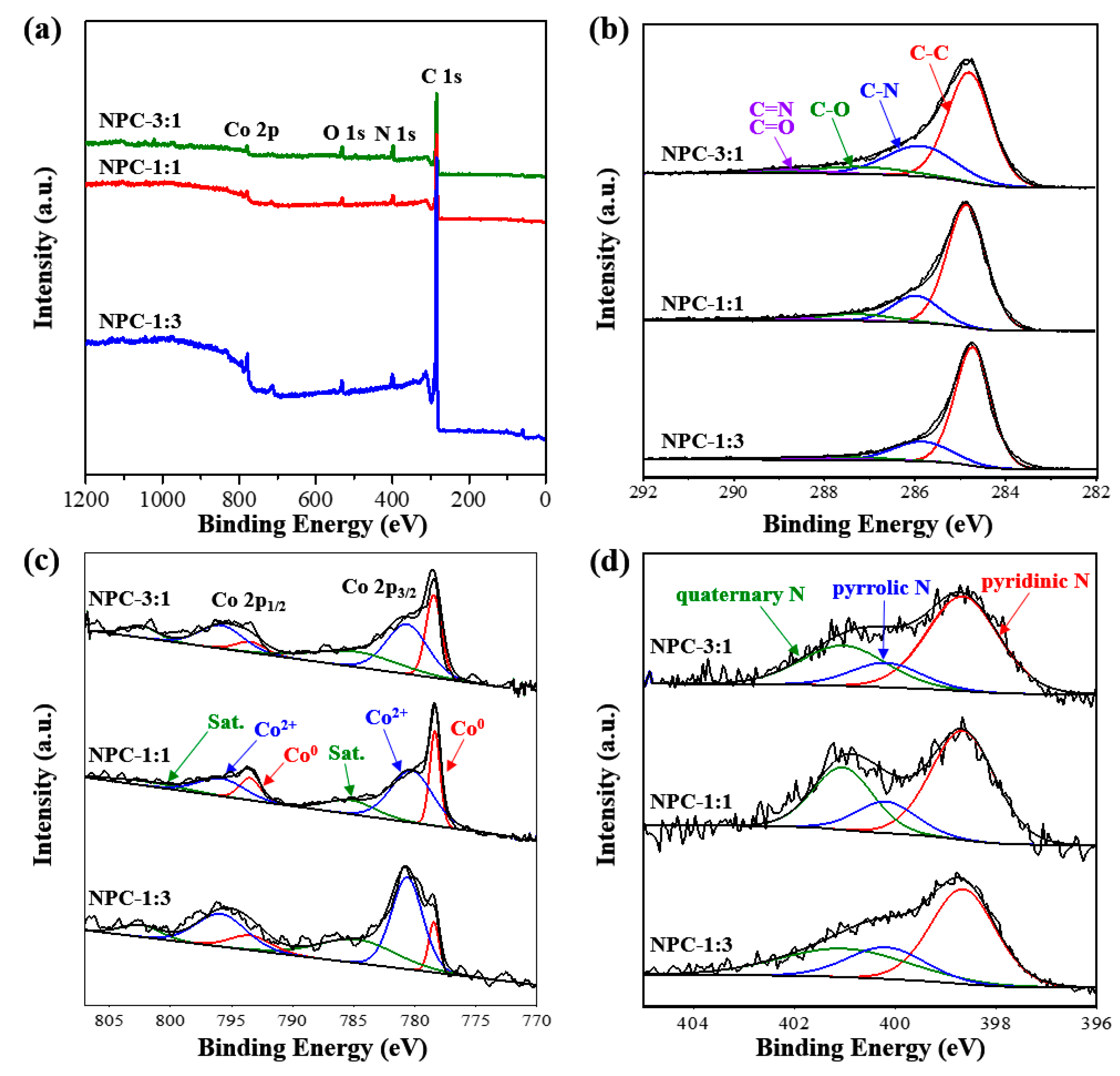
| NPC-3:1 | 0.37 | 0.70 | 83.1 | 10.8 | 5.08 |
| NPC-1:1 | - | 1.11 | 89.5 | 6.42 | 3.00 |
| NPC-1:3 | - | 0.94 | 93.5 | 3.70 | 1.84 |
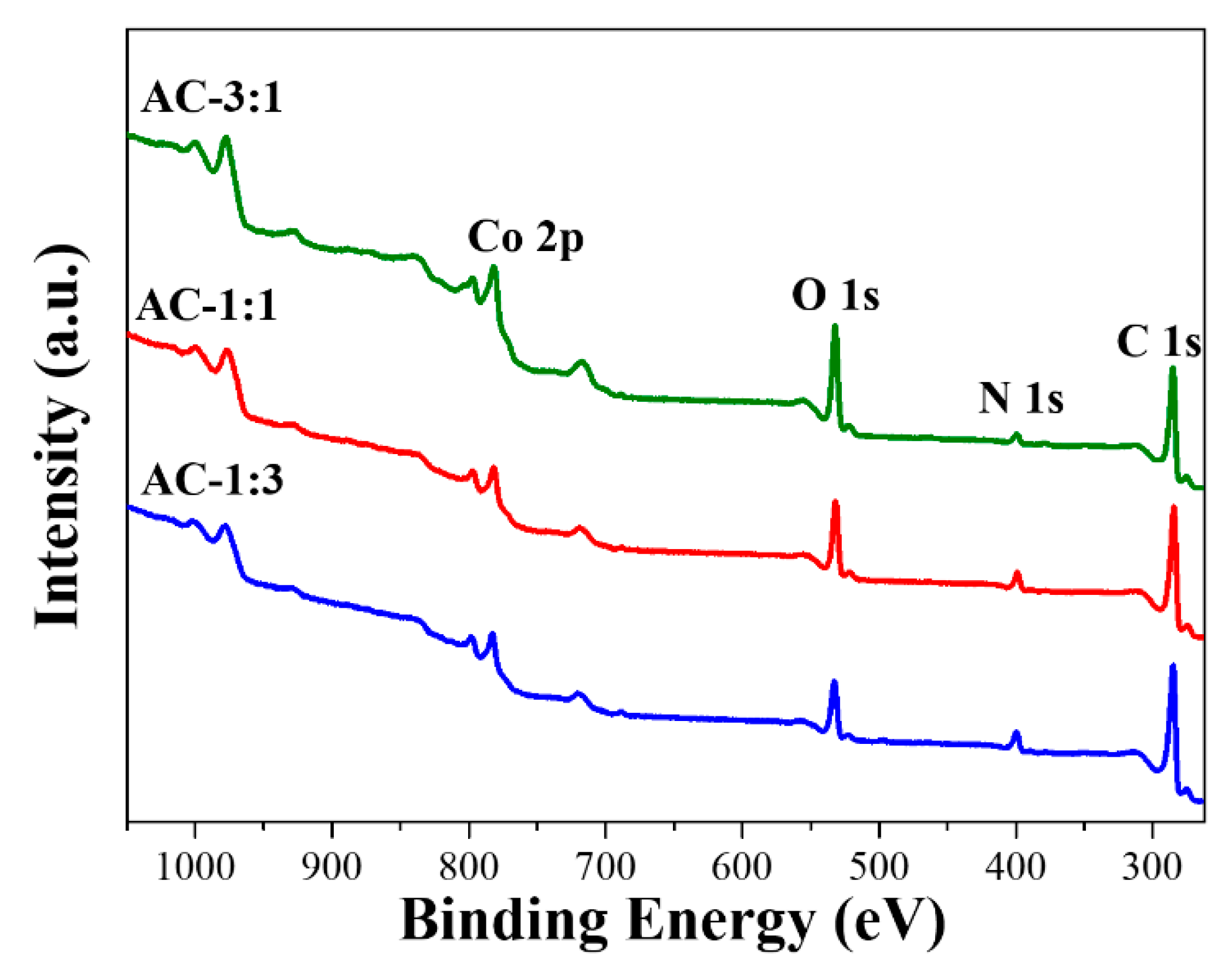
| AC-3:1 | 0.05 | 2.50 | 84.03 | 3.92 | 9.50 |
| AC-1:1 | - | 5.28 | 78.63 | 2.36 | 13.73 |
| AC-1:3 | 0.01 | 3.35 | 80.30 | 6.05 | 10.28 |
© 2019 by the authors. Licensee MDPI, Basel, Switzerland. This article is an open access article distributed under the terms and conditions of the Creative Commons Attribution (CC BY) license (http://creativecommons.org/licenses/by/4.0/).
Share and Cite
Marpaung, F.; Park, T.; Kim, M.; Yi, J.W.; Lin, J.; Wang, J.; Ding, B.; Lim, H.; Konstantinov, K.; Yamauchi, Y.; et al. Gram-Scale Synthesis of Bimetallic ZIFs and Their Thermal Conversion to Nanoporous Carbon Materials. Nanomaterials 2019, 9, 1796. https://doi.org/10.3390/nano9121796
Marpaung F, Park T, Kim M, Yi JW, Lin J, Wang J, Ding B, Lim H, Konstantinov K, Yamauchi Y, et al. Gram-Scale Synthesis of Bimetallic ZIFs and Their Thermal Conversion to Nanoporous Carbon Materials. Nanomaterials. 2019; 9(12):1796. https://doi.org/10.3390/nano9121796
Chicago/Turabian StyleMarpaung, Freddy, Teahoon Park, Minjun Kim, Jin Woo Yi, Jianjian Lin, Jie Wang, Bing Ding, Hyunsoo Lim, Konstantin Konstantinov, Yusuke Yamauchi, and et al. 2019. "Gram-Scale Synthesis of Bimetallic ZIFs and Their Thermal Conversion to Nanoporous Carbon Materials" Nanomaterials 9, no. 12: 1796. https://doi.org/10.3390/nano9121796