
Textile-Based Electronic Components for Energy Applications: Principles, Problems, and Perspective


Abstract
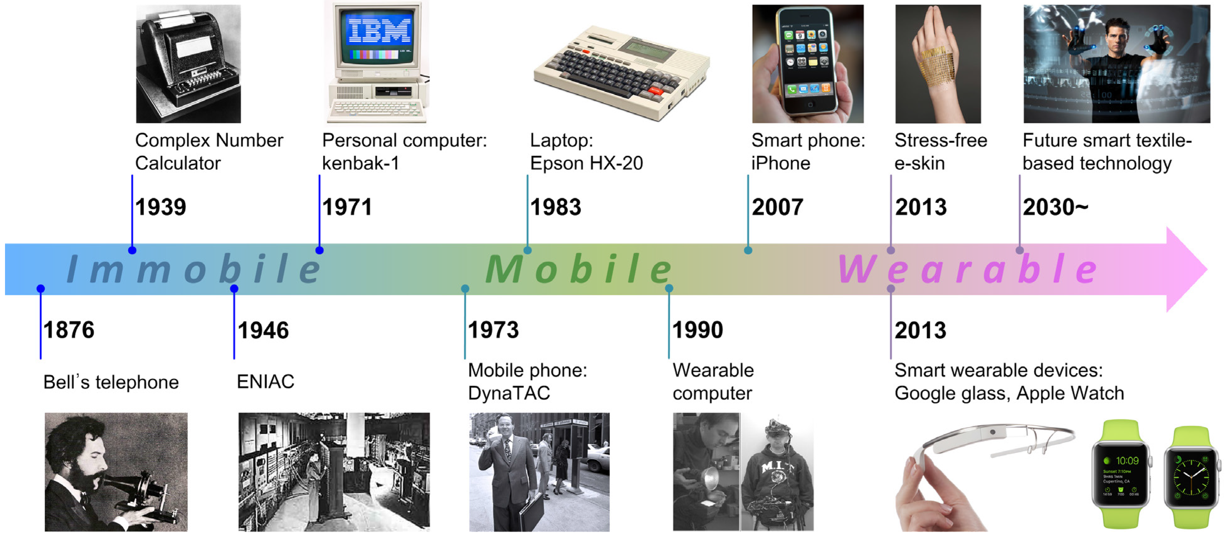
:1. Introduction

2. Conductive Textile: Materials and Fabrication
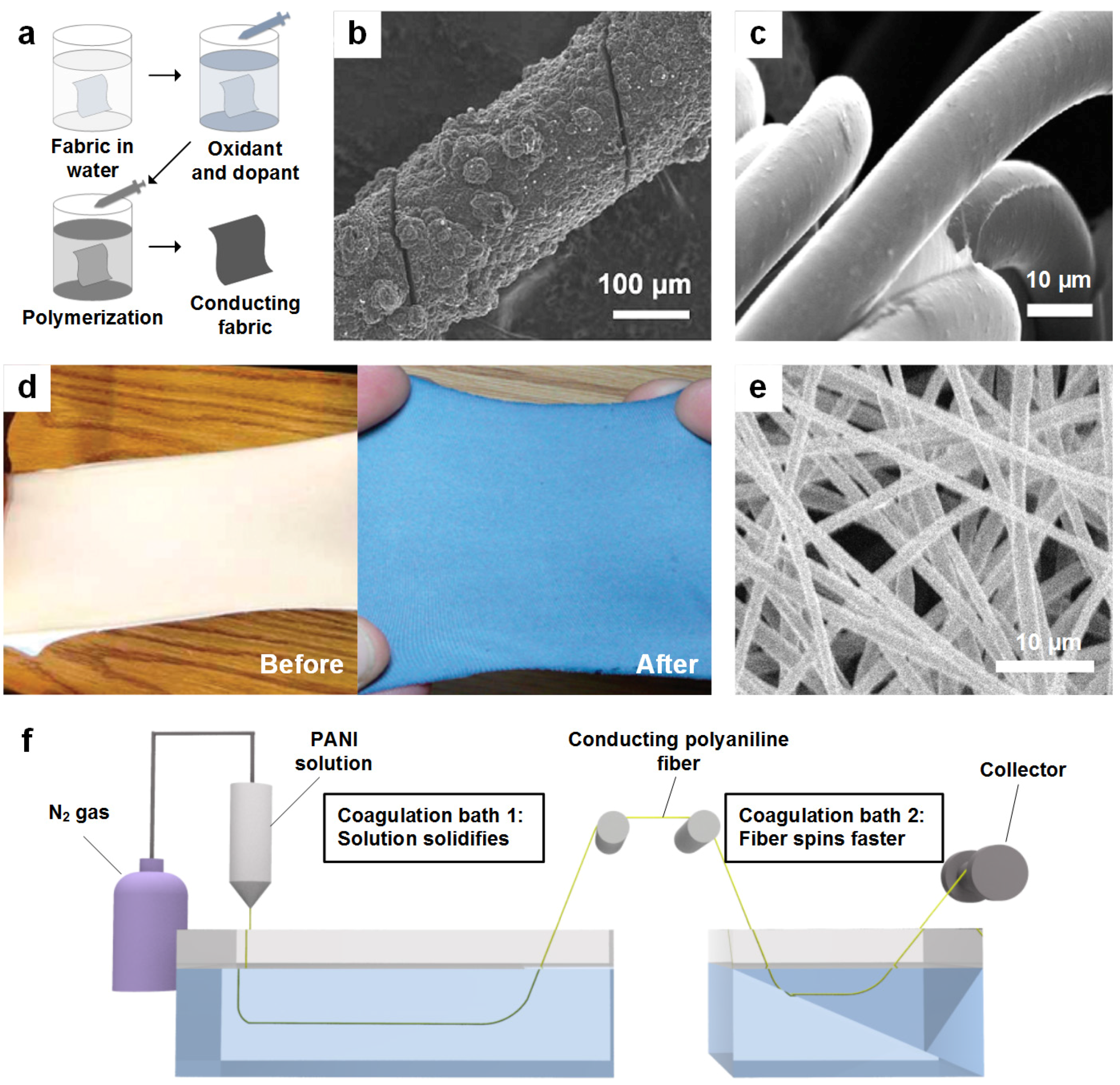
2.1. Polymer-Based Conductive Textiles


| Structure of conductive textile | Material use to prepare or to coat on fibers | Merits of Conductive textiles | Technique used to fabricate conductive textile | Advantages of growth technique | Disadvantages of growth technique | Electrical property | Ref. |
|---|---|---|---|---|---|---|---|
| Polymer-based | Polypyrrole | Chemical and environment stable | Functional dopant induced process | Novel & Easy process, High Yield easily deposit on fabric surface | Need to optimize dopant concentration for better conductivity results | 120–130 S/cm | [78] |
| Polyaniline | Cost effective, stable | Wet Spinning | Produced fibers show high electronic and mechanical strength, fabricated thick fibers | Need to combine Individual fibers | 140-750 S/cm | [79,80,81] | |
| PEDOT:PSS | Highly conductive good thermal and chemical stability | Dip Coating | Simple process | Coating is slow, tide lines can forms | 0.4–2.0 S/cm | [68,82] | |
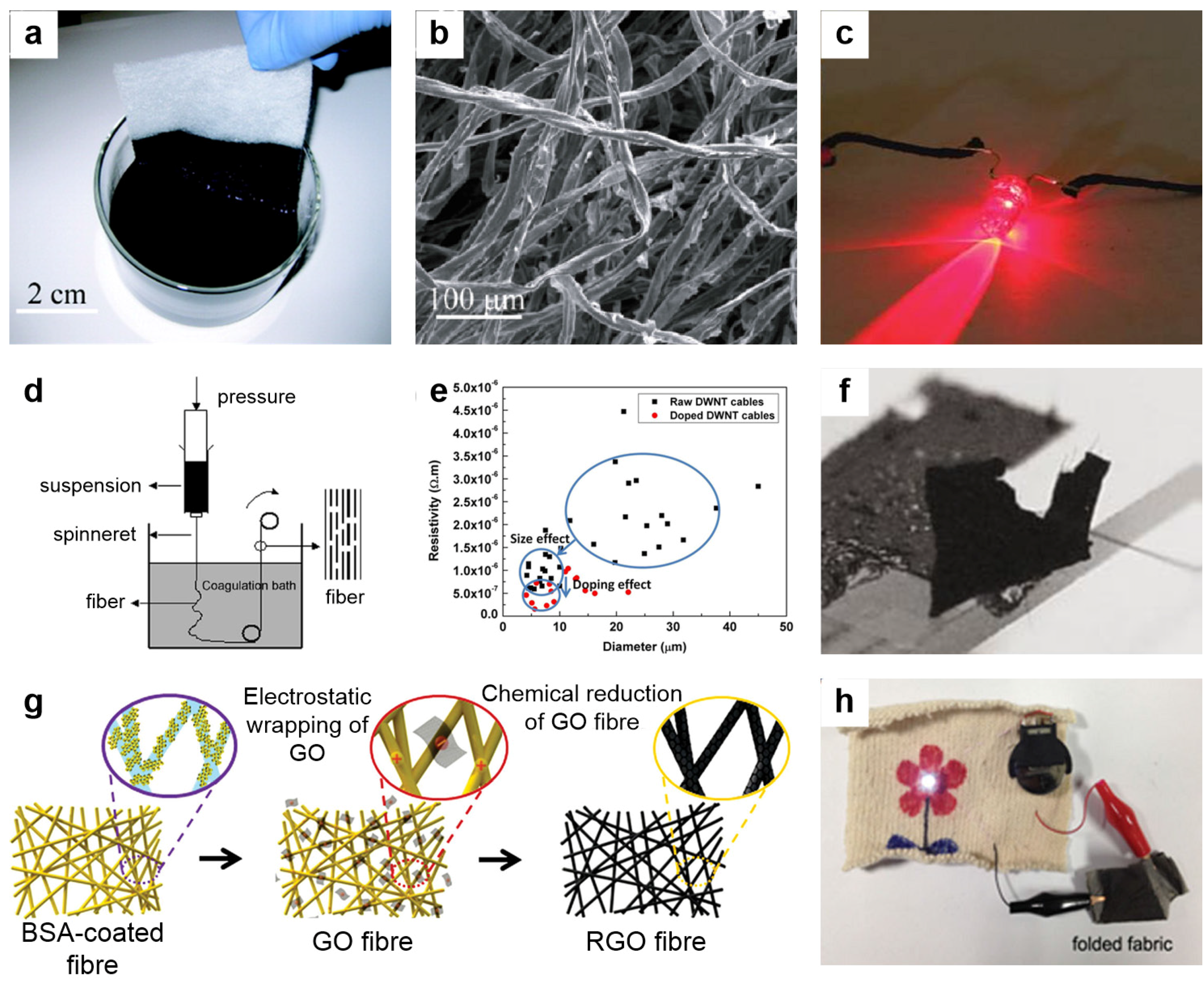
| Carbon-based | Graphene | Highly conductive & stable, high strength | Electrostatic self-assembly with BSA followed by chemical reduction | Easy to attach graphene oxide films to textiles | Multistep process, wrinkles observed on surface of samples | 10–20 S/cm | [83,84] |
| Carbon nanotubes | Conductive, high mechanical strength | Wet spinning | Continuous long length (cm) CNT yarns | Slow processing | 125–3000 S/cm | [85,86,87] | |
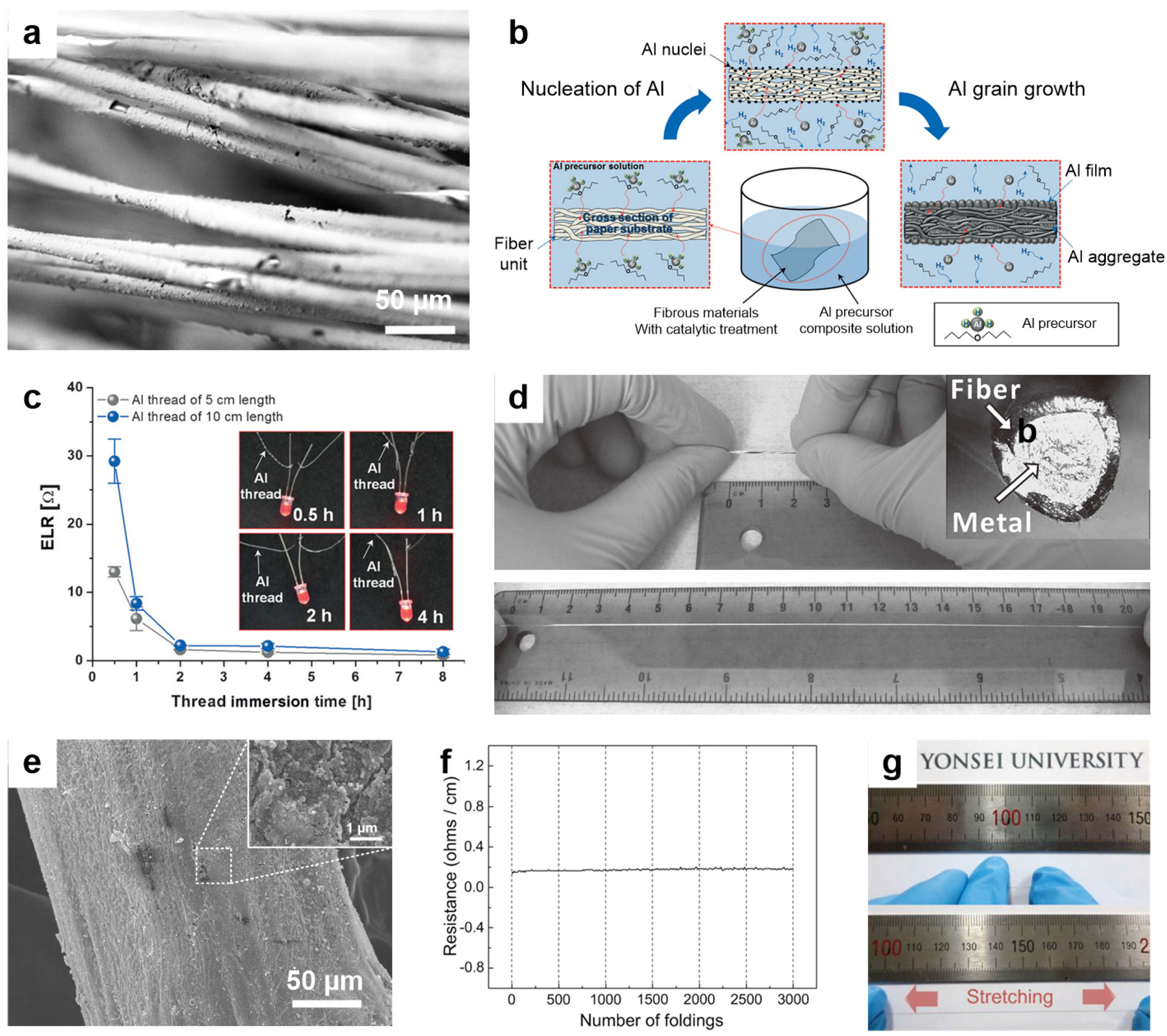
| Metal-based | Al-coated conductive paper | Stable, conductive, stretchable | Chemical solution process | Low cost, Vacuum not required, Direct deposition of Al on fibers | Need a suitable catalyst for decomposition process | 19 mΩ/□ | [88] |
| AgNP/Ag nanowires | Conductive | Wet spinning | Simple, highly conductive material | Need optimization of suitable solvents and coagulation liquids | 2200–5400 S/cm | [89,90] |
2.2. Carbon-Based Conductive Textile

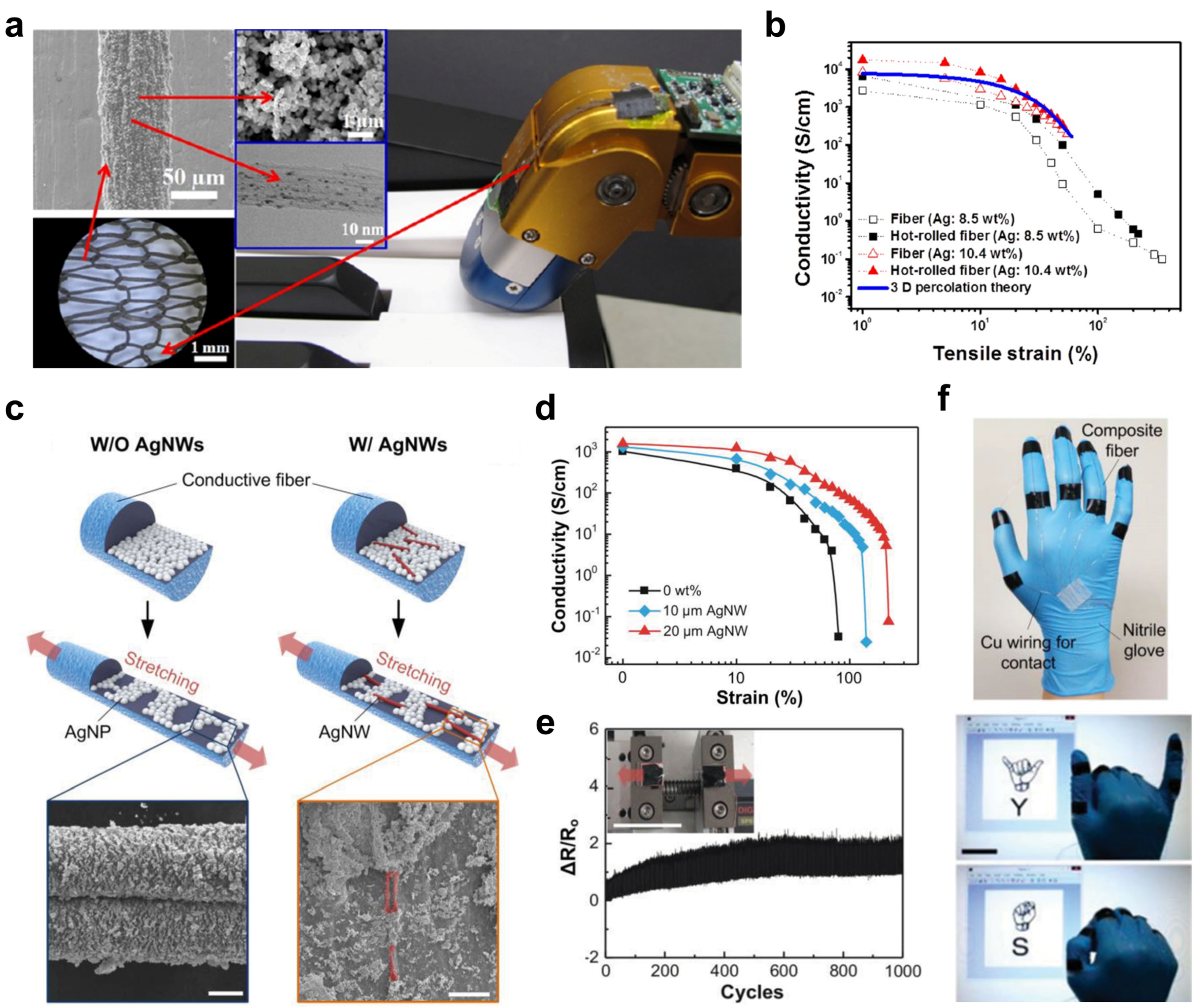
2.3. Metal-Based Conductive Textiles

3. Textile Electronic Components
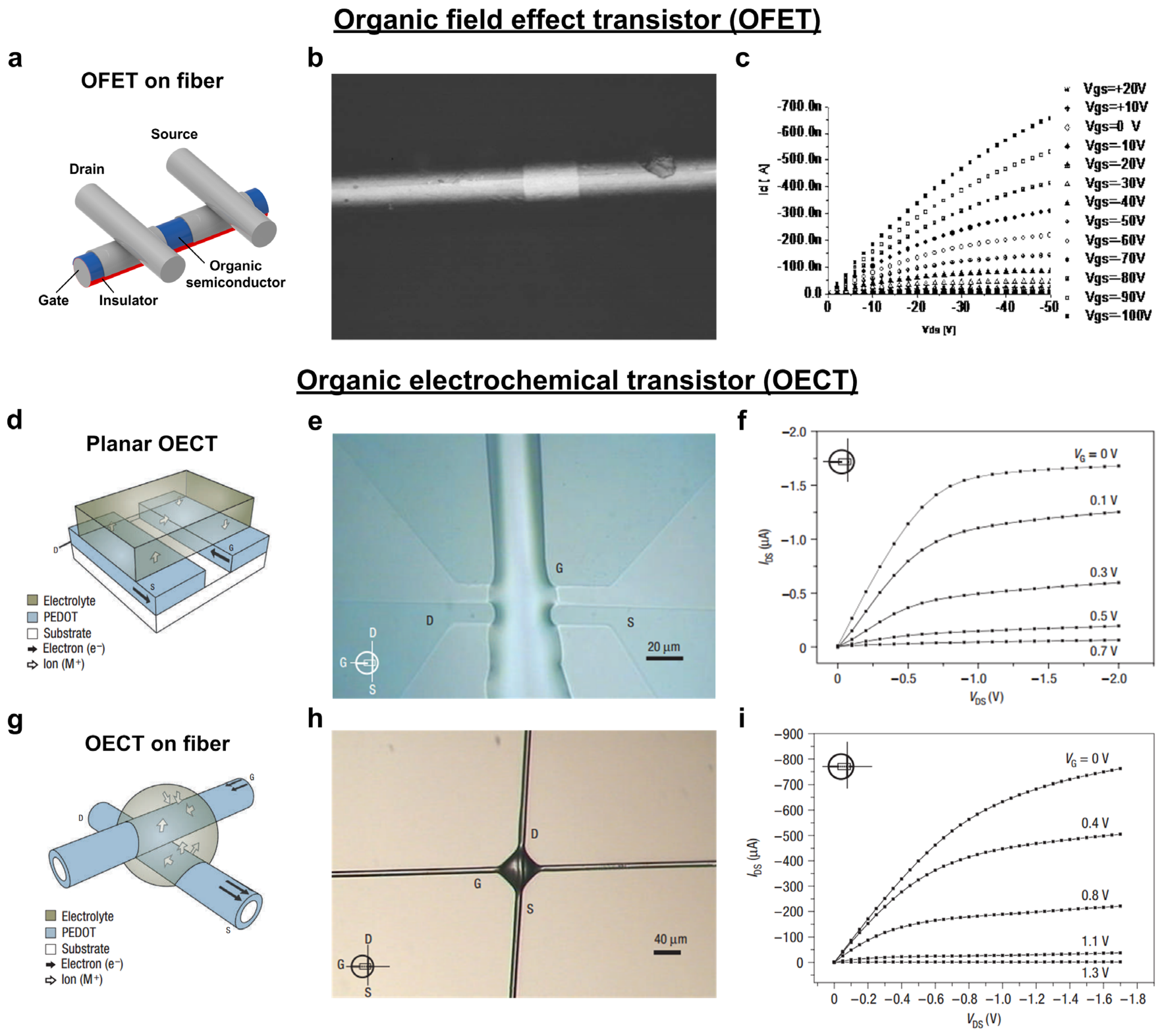
3.1. Transistor

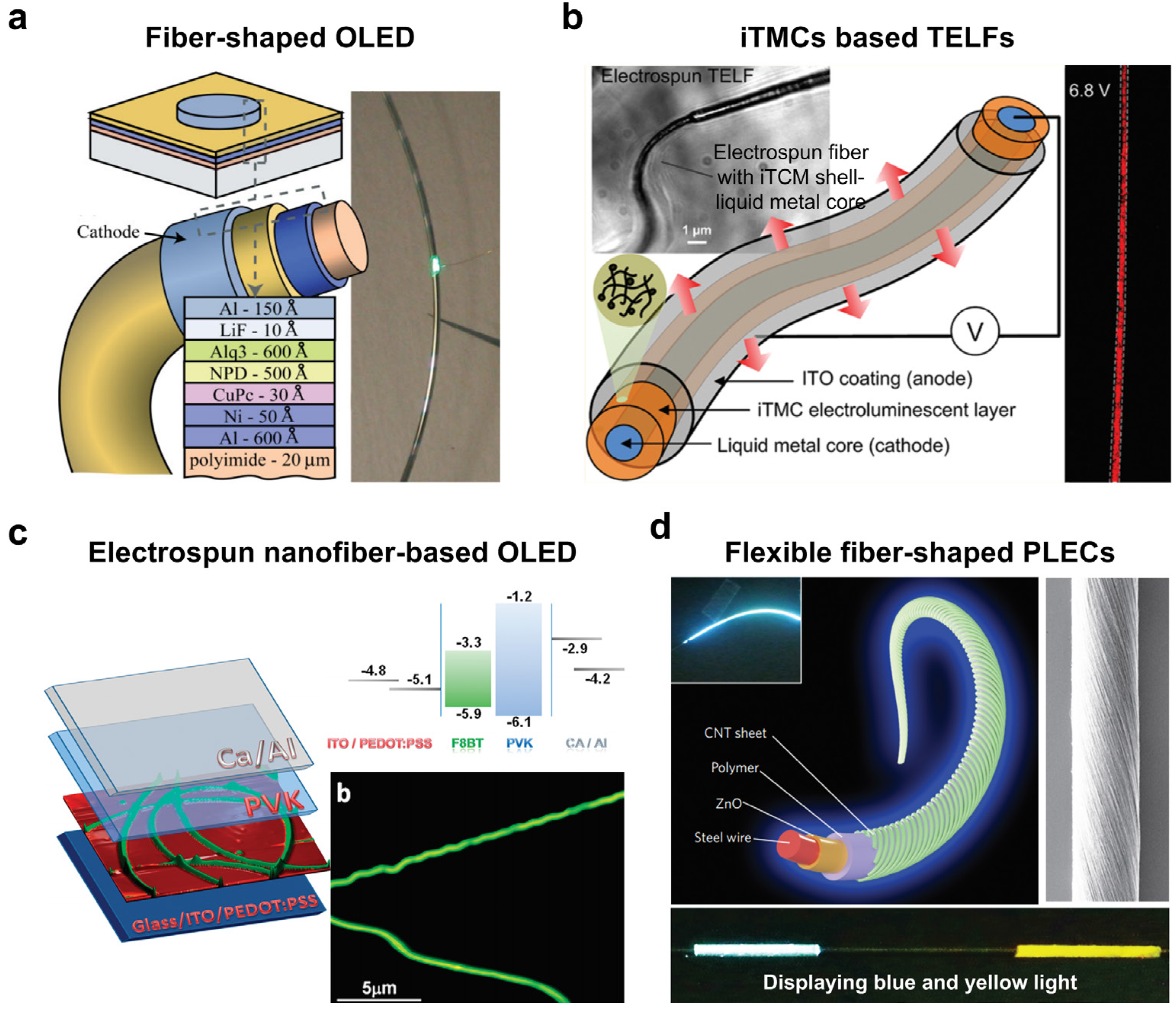
3.2. Light-Emitting Diodes

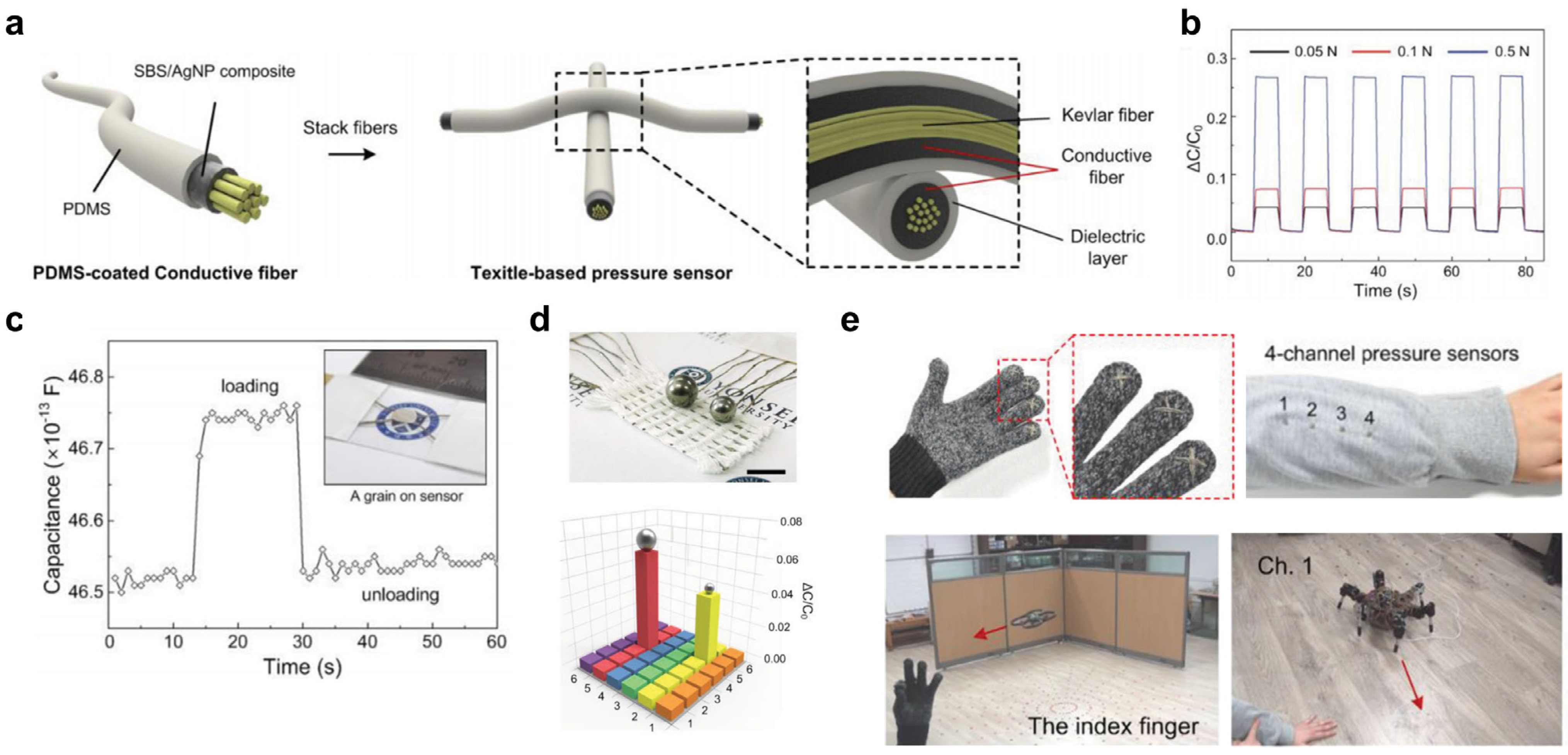
3.3. High Sensitivity Sensors


4. Textile-Based Energy Applications: Energy Harvesting & Storage
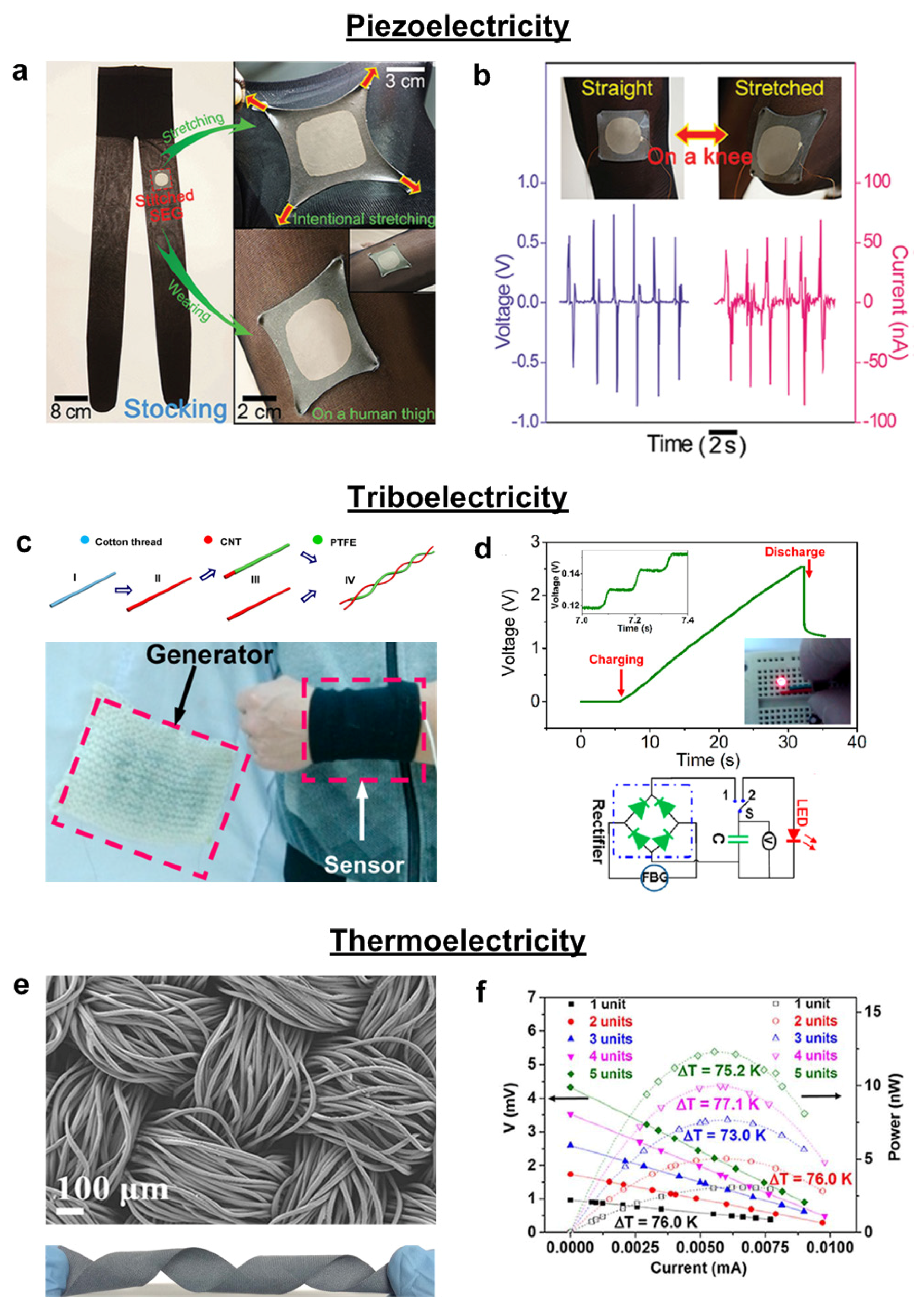
4.1. Energy Harvesting from Human Motion

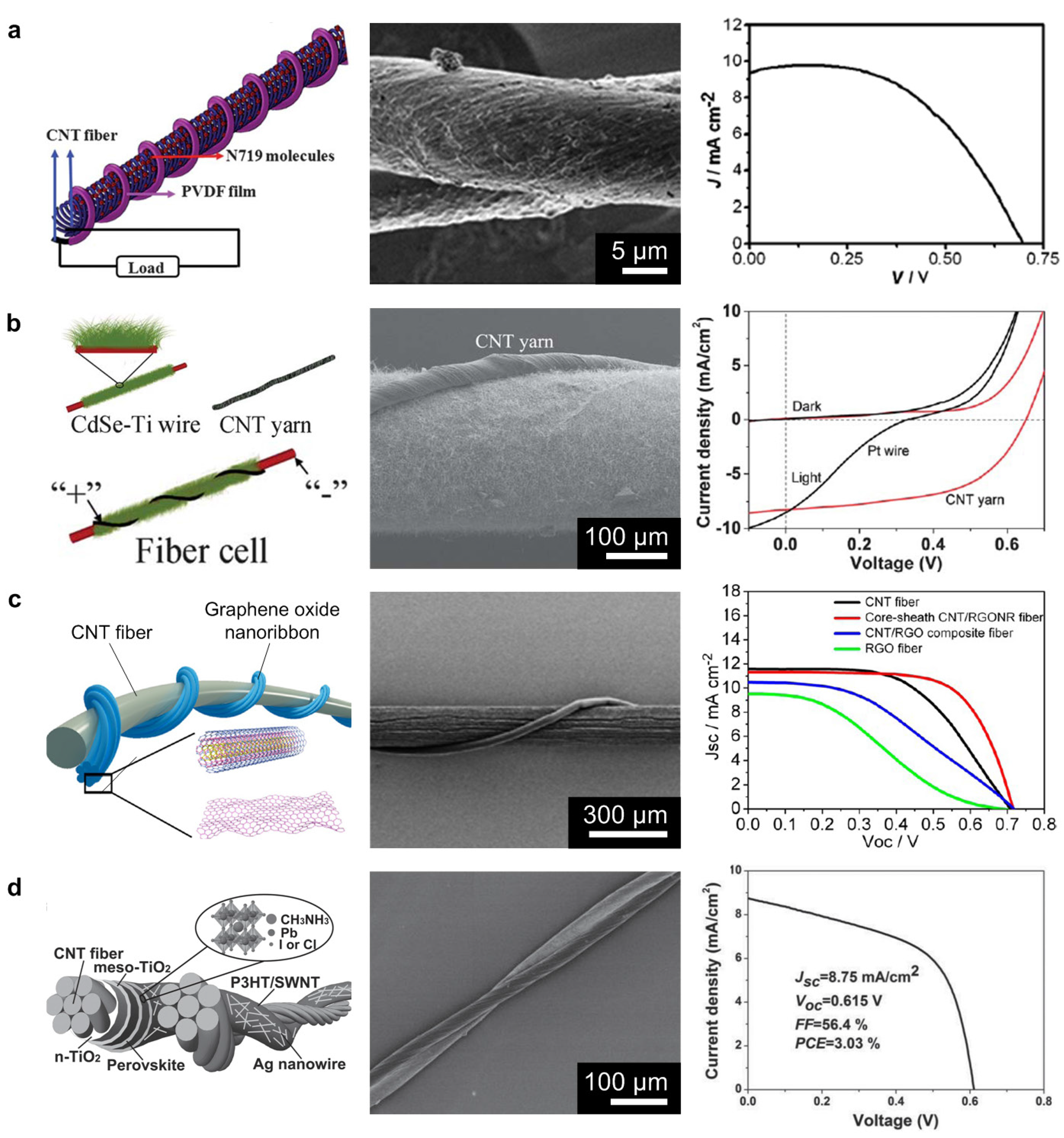
4.2. Solar Cells on Textiles

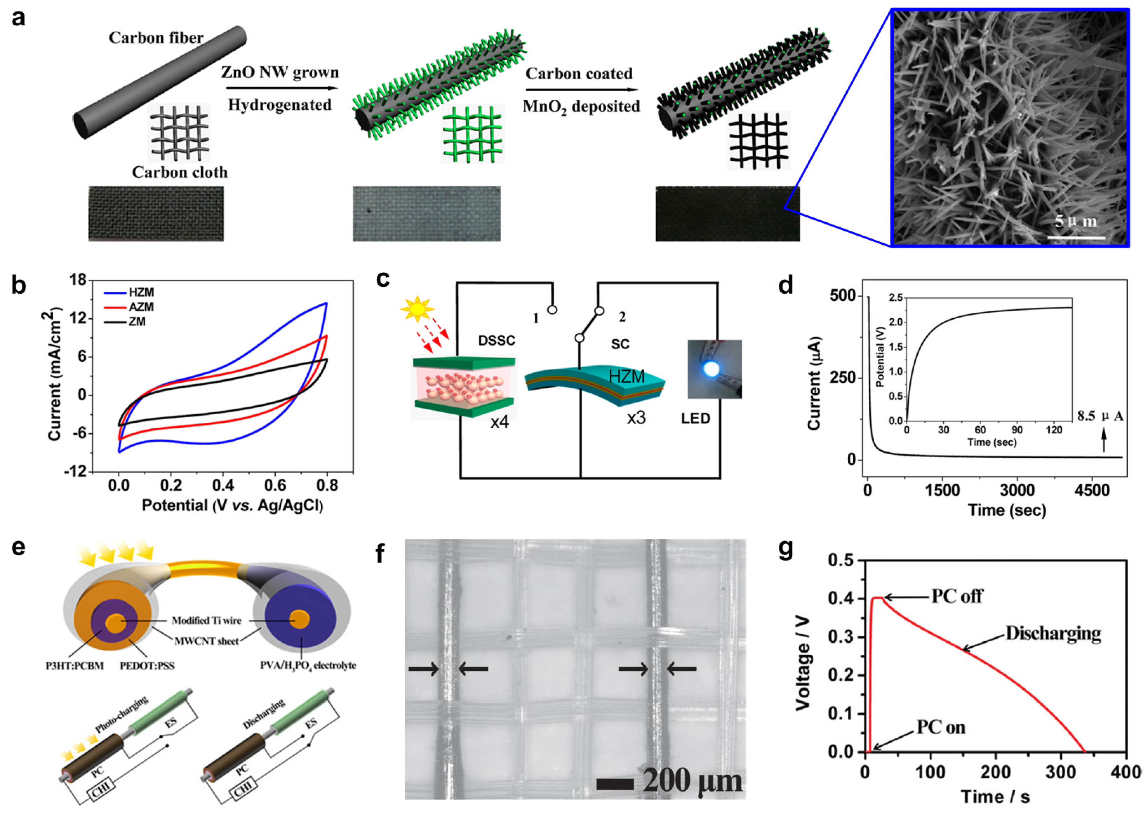
4.3. Fabric-Based Supercapacitors

5. Current Limitations of Wearable E-textiles
6. Conclusions and Perspectives
Acknowledgments
Author Contributions
Conflicts of Interest
References
- Csapó, Á.; Wersényi, G.; Nagy, H.; Stockman, T. A survey of assistive technologies and applications for blind users on mobile platforms: A review and foundation for research. J. Multimodal User Interfaces 2015. [Google Scholar] [CrossRef] [Green Version]
- Lewis, Z.H.; Lyons, E.J.; Jarvis, J.M.; Baillargeon, J. Using an electronic activity monitor system as an intervention modality: A systematic review. BMC Public Health 2015, 15, 585–600. [Google Scholar] [CrossRef] [PubMed]
- Vanveerdeghem, P.; Van Torre, P.; Thielens, A.; Knockaert, J.; Joseph, W.; Rogier, H. Compact personal distributed wearable exposimeter. IEEE Sens. J. 2015, 15, 4393–4401. [Google Scholar] [CrossRef]
- Yun, J.Y.; Hong, W.G.; Choi, N.-J.; Kim, H.B.; Jun, Y.; Lee, H.-K. Ultrasensitive and highly selective graphene-based single yarn for use in wearable gas sensor. Sci. Rep. 2015, 5, 10904–10910. [Google Scholar] [CrossRef] [PubMed]
- Bai, P.F.; Hayes, R.A.; Jin, M.; Shui, L.; Yi, Z.C.; Wang, L.; Zhang, X.; Zhou, G. Review of paper-like display technologies (invited review). Prog. Electromagn. Res. 2014, 147, 95–116. [Google Scholar] [CrossRef]
- Patel, S.; Park, H.; Bonato, P.; Chan, L.; Rodgers, M. A review of wearable sensors and systems with application in rehabilitation. J. Neuroeng. Rehabil. 2012, 9, 1–17. [Google Scholar] [CrossRef] [PubMed]
- Bell, A.G. Phone and Other Inventions. Available online: http://www.carnetdevol.org/Bell/Phone.html (accessed on 3 August 2015).
- Tropp, H. Computer report VII: The effervescent years: A retrospective: Behind the computer revolution lay the vision and perseverance of a handful of pioneers committed to open information exchange. IEEE Spectr. 1974, 11, 70–79. [Google Scholar] [CrossRef]
- Goldstine, H.H.; Goldstine, A. The electronic numerical integrator and computer (ENIAC). IEEE Ann. Hist. Comput. 1996, 18, 10–16. [Google Scholar] [CrossRef]
- Myslewski, R. File:Ibm pcjr with display.jpg. Available online: https://commons.wikimedia.org/wiki/File:Ibm_pcjr_with_display.jpg (accessed on 14 July 2015).
- Gilbert, D. Mobile Phone Celebrates 40th Birthday. Available online: http://www.ibtimes.co.uk/mobile-phone-40-years-motorola-dynatac-history-453057 (accessed on 3 August 2015).
- Steven, S. Epson-hx-20. Available online: https://upload.wikimedia.org/wikipedia/commons/8/8d/Epson-hx-20.jpg (accessed on 14 July 2015).
- Mann, S. Smart clothing: The wearable computer and wearcam. Pers. Technol. 1997, 1, 21–27. [Google Scholar] [CrossRef]
- Ritchie, R. History of iPhone: Apple reinvents the phone. Available online: http://www.imore.com/history-iphone-2g (accessed on 3 August 2015).
- Ackerman, E. Google gets in your face. IEEE Spectr. 2013, 50, 26–29. [Google Scholar]
- Apple. Apple Watch. Available online: http://www.apple.com/kr/watch/gallery/ (accessed on 3 August 2015).
- Popat, K.A.; Sharma, P. Wearable computer applications a future perspective. Int. J. Eng. Innov. Technol. 2013, 3, 213–217. [Google Scholar]
- Someya Group Organic Transistor Lab Press Kits. Available online: http://www.ntech.t.u-tokyo.ac.jp/en/press/press_for_media/index.html (accessed on 3 August 2015).
- Caron, N. Meet the Rest of the Cast for Fox’s Minority Report TV series. Available online: http://www.blastr.com/2015-3-3/meet-rest-cast-foxs-minority-report-tv-series (accessed on 3 August 2015).
- Lee, J.; Kwon, H.; Seo, J.; Shin, S.; Koo, J.H.; Pang, C.; Son, S.; Kim, J.H.; Jang, Y.H.; Kim, D.E.; Lee, T. Conductive fiber-based ultrasensitive textile pressure sensor for wearable electronics. Adv. Mater. 2015, 27, 2433–2439. [Google Scholar] [CrossRef] [PubMed]
- Seesaard, T.; Lorwongtragool, P.; Kerdcharoen, T. Development of fabric-based chemical gas sensors for use as wearable electronic noses. Sensors 2015, 15, 1885–1902. [Google Scholar] [CrossRef] [PubMed]
- Skrzetuska, E.; Puchalski, M.; Krucińska, I. Chemically driven printed textile sensors based on graphene and carbon nanotubes. Sensors 2014, 14, 16816–16828. [Google Scholar] [CrossRef] [PubMed]
- Lanata, A.; Valenza, G.; Nardelli, M.; Gentili, C.; Scilingo, E.P. Complexity index from a personalized wearable monitoring system for assessing remission in mental health. IEEE J. Biomed. Health Inform. 2015, 19, 132–139. [Google Scholar] [CrossRef] [PubMed]
- Zheng, Y.-L.; Ding, X.-R.; Poon, C.C.Y.; Lo, B.P.L.; Zhang, H.; Zhou, X.-L.; Yang, G.-Z.; Zhao, N.; Zhang, Y.-T. Unobtrusive sensing and wearable devices for health informatics. IEEE Trans. Biomed. Eng. 2014, 61, 1538–1554. [Google Scholar] [CrossRef] [PubMed]
- Zheng, N.; Wu, Z.; Lin, M.; Yang, L.T. Enhancing battery efficiency for pervasive health-monitoring systems based on electronic textiles. IEEE Trans. Inf. Technol. Biomed. 2010, 14, 350–359. [Google Scholar] [CrossRef] [PubMed]
- Paradiso, R.; Loriga, G.; Taccini, N. A wearable health care system based on knitted integrated sensors. IEEE Trans. Inf. Technol. Biomed. 2005, 9, 337–344. [Google Scholar] [CrossRef] [PubMed]
- Quinlan, M.; Mayhew, C. The effects of outsourcing on occupational health and safety: A comparative study of factory-based workers and outworkers in the Australian clothing industry. Int. J. Health Serv. 1999, 29, 83–107. [Google Scholar] [CrossRef]
- Rofouei, M.; Potkonjak, M.; Sarrafzadeh, M. Energy efficient collaborative sensing-based design: Soft keyboard case study. IEEE Trans. Hum. Mach. Syst. 2014, 44, 115–124. [Google Scholar] [CrossRef]
- Yoo, H.-J. Your heart on your sleeve: Advances in textile-based electronics are weaving computers right into the clothes we wear. IEEE Solid State Circuits Mag. 2013, 5, 59–70. [Google Scholar]
- Li, W.; Zhu, L.; Gu, J.; Liu, H. Microwave absorption properties of fabric coated absorbing material using modified carbonyl iron power. Compos. Part B Eng. 2011, 42, 626–630. [Google Scholar] [CrossRef]
- Moro, R.; Agneessens, S.; Rogier, H.; Dierck, A.; Bozzi, M. Textile microwave components in substrate integrated waveguide technology. IEEE Trans. Microw. Theory Tech. 2015, 63, 422–432. [Google Scholar] [CrossRef]
- Castano, L.M.; Flatau, A.B. Smart fabric sensors and E-textile technologies: A review. Smart Mater. Struct. 2014, 23, 053001–053027. [Google Scholar] [CrossRef]
- Stoppa, M.; Chiolerio, A. Wearable electronics and smart textiles: A critical review. Sensors 2014, 14, 11957–11992. [Google Scholar] [CrossRef] [PubMed]
- Zięba, J.; Frydrysiak, M. Textronics–electrical and electronic textiles. Sensors for breathing frequency measurement. Fibres Text. East. Eur. 2006, 14, 43–48. [Google Scholar]
- Sun, H.; You, X.; Yang, Z.; Deng, J.; Peng, H. Winding ultrathin, transparent, and electrically conductive carbon nanotube sheets into high-performance fiber-shaped dye-sensitized solar cells. J. Mater. Chem. A 2013, 1, 12422–12425. [Google Scholar] [CrossRef]
- Weintraub, B.; Wei, Y.; Wang, Z.L. Optical fiber/nanowire hybrid structures for efficient three-dimensional dye-sensitized solar cells. Angew. Chem. Int. Ed. 2009, 48, 8981–8985. [Google Scholar] [CrossRef] [PubMed]
- Liu, D.; Zhao, M.; Li, Y.; Bian, Z.; Zhang, L.; Shang, Y.; Xia, X.; Zhang, S.; Yun, D.; Liu, Z.; Cao, A.; Huang, C. Solid-state, polymer-based fiber solar cells with carbon nanotube electrodes. ACS Nano 2012, 6, 11027–11034. [Google Scholar] [CrossRef] [PubMed]
- Li, R.; Xiang, X.; Tong, X.; Zou, J.; Li, Q. Wearable double-twisted fibrous perovskite solar cell. Adv. Mater. 2015, 27, 3831–3835. [Google Scholar] [CrossRef] [PubMed]
- Lee, J.B.; Subramanian, V. Weave patterned organic transistors on fiber for E-textiles. IEEE Trans. Electron Devices 2005, 52, 269–275. [Google Scholar] [CrossRef]
- Tao, X.; Koncar, V.; Dufour, C. Geometry pattern for the wire organic electrochemical textile transistor. J. Electrochem. Soc. 2011, 158, H572–H577. [Google Scholar] [CrossRef]
- Kylberg, W.; de Castro, F.A.; Chabrecek, P.; Sonderegger, U.; Chu, B.T.-T.; Nüesch, F.; Hany, R. Woven electrodes for flexible organic photovoltaic cells. Adv. Mater. 2011, 23, 1015–1019. [Google Scholar] [CrossRef] [PubMed]
- Zhang, Z.; Guo, K.; Li, Y.; Li, X.; Guan, G.; Li, H.; Luo, Y.; Zhao, F.; Zhang, Q.; Wei, B.; Pei, Q.; Peng, H. A colour-tunable, weavable fibre-shaped polymer light-emitting electrochemical cell. Nat. Photonics 2015, 9, 233–238. [Google Scholar] [CrossRef]
- Vohra, V.; Giovanella, U.; Tubino, R.; Murata, H.; Botta, C. Electroluminescence from conjugated polymer electrospun nanofibers in solution processable organic light-emitting diodes. ACS Nano 2011, 5, 5572–5578. [Google Scholar] [CrossRef] [PubMed]
- Bedeloglu, A.; Demir, A.; Bozkurt, Y.; Sariciftci, N.S. A flexible textile structure based on polymeric photovoltaics using transparent cathode. Synth. Met. 2009, 159, 2043–2048. [Google Scholar] [CrossRef]
- Jost, K.; Dion, G.; Gogotsi, Y. Textile energy storage in perspective. J. Mater. Chem. A 2014, 2, 10776–10787. [Google Scholar] [CrossRef]
- Wang, Z.L. Towards self-powered nanosystems: From nanogenerators to nanopiezotronics. Adv. Funct. Mater. 2008, 18, 3553–3567. [Google Scholar] [CrossRef]
- Das, T.K.; Prusty, S. Review on conducting polymers and their applications. Polym. Plast. Technol. Eng. 2012, 51, 1487–1500. [Google Scholar] [CrossRef]
- Wegner, G. Polymers with metal-like conductivity—A review of their synthesis, structure and properties. Angew. Chem. Int. Ed. Engl. 1981, 20, 361–381. [Google Scholar] [CrossRef]
- Patil, A.O.; Heeger, A.J.; Wudl, F. Optical properties of conducting polymers. Chem. Rev. 1988, 88, 183–200. [Google Scholar] [CrossRef]
- Gerard, M.; Chaubey, A.; Malhotra, B.D. Application of conducting polymers to biosensors. Biosens. Bioelectron. 2002, 17, 345–359. [Google Scholar] [CrossRef]
- Janata, J.; Josowicz, M. Conducting polymers in electronic chemical sensors. Nat. Mater. 2003, 2, 19–24. [Google Scholar] [CrossRef] [PubMed]
- Svirskis, D.; Travas-Sejdic, J.; Rodgers, A.; Garg, S. Electrochemically controlled drug delivery based on intrinsically conducting polymers. J. Controlled Release 2010, 146, 6–15. [Google Scholar] [CrossRef] [PubMed]
- Pernaut, J.-M.; Reynolds, J.R. Use of conducting electroactive polymers for drug delivery and sensing of bioactive molecules. A redox chemistry approach. J. Phys. Chem. B 2000, 104, 4080–4090. [Google Scholar] [CrossRef]
- Tallman, D.E.; Spinks, G.; Dominis, A.; Wallace, G.G. Electroactive conducting polymers for corrosion control. J. Solid State Electrochem. 2001, 6, 73–84. [Google Scholar] [CrossRef]
- Hohnholz, D.; Okuzaki, H.; MacDiarmid, A.G. Plastic electronic devices through line patterning of conducting polymers. Adv. Funct. Mater. 2005, 15, 51–56. [Google Scholar] [CrossRef]
- Green, R.A.; Lovell, N.H.; Wallace, G.G.; Poole-Warren, L.A. Conducting polymers for neural interfaces: Challenges in developing an effective long-term implant. Biomaterials 2008, 29, 3393–3399. [Google Scholar] [CrossRef] [PubMed]
- Olmedo, L.; Hourquebie, P.; Jousse, F. Microwave absorbing materials based on conducting polymers. Adv. Mater. 1993, 5, 373–377. [Google Scholar] [CrossRef]
- Malinauskas, A. Electrocatalysis at conducting polymers. Synth. Met. 1999, 107, 75–83. [Google Scholar] [CrossRef]
- Kingsborough, R.P.; Swager, T.M. Electrocatalytic conducting polymers: Oxygen reduction by a polythiophene-cobalt salen hybrid. Chem. Mater. 2000, 12, 872–874. [Google Scholar] [CrossRef]
- Shirakawa, H.; Louis, E.J.; MacDiarmid, A.G.; Chiang, C.K.; Heeger, A.J. Synthesis of electrically conducting organic polymers: Halogen derivatives of polyacetylene, (CH)x. J. Chem. Soc. Chem. Commun. 1977, 578–580. [Google Scholar] [CrossRef]
- Schreuder-Gibson, H.L.; Truong, Q.; Walker, J.E.; Owens, J.R.; Wander, J.D.; Jones, W.E. Chemical and biological protection and detection in fabrics for protective clothing. MRS Bull. 2003, 28, 574–578. [Google Scholar] [CrossRef]
- Cochrane, C.; Koncar, V.; Lewandowski, M.; Dufour, C. Design and development of a flexible strain sensor for textile structures based on a conductive polymer composite. Sensors 2007, 7, 473–492. [Google Scholar] [CrossRef]
- De Rossi, D.; Carpi, F.; Lorussi, F.; Mazzoldi, A.; Paradiso, R.; Scilingo, E.P.; Tognetti, A. Electroactive fabrics and wearable biomonitoring devices. AUTEX Res. J. 2003, 3, 180–185. [Google Scholar]
- Smith, D. Smart clothes and wearable technology. AI Soc. 2007, 22, 1–3. [Google Scholar] [CrossRef]
- Park, S.; Jayaraman, S. Smart textiles: Wearable electronic systems. MRS Bull. 2003, 28, 585–591. [Google Scholar] [CrossRef]
- Kim, M.S.; Kim, H.K.; Byun, S.W.; Jeong, S.H.; Hong, Y.K.; Joo, J.S.; Song, K.T.; Kim, J.K.; Lee, C.J.; Lee, J.Y. PET fabric/polypyrrole composite with high electrical conductivity for EMI shielding. Synth. Met. 2002, 126, 233–239. [Google Scholar] [CrossRef]
- Varesano, A.; Dall’Acqua, L.; Tonin, C. A study on the electrical conductivity decay of polypyrrole coated wool textiles. Polym. Degrad. Stab. 2005, 89, 125–132. [Google Scholar] [CrossRef]
- Ding, Y.; Invernale, M.A.; Sotzing, G.A. Conductivity trends of PEDOT-PSS impregnated fabric and the effect of conductivity on electrochromic textile. ACS Appl. Mater. Interfaces 2010, 2, 1588–1593. [Google Scholar] [CrossRef] [PubMed]
- Gospodinova, N.; Terlemezyan, L. Conducting polymers prepared by oxidative polymerization: Polyaniline. Prog. Polym. Sci. 1998, 23, 1443–1484. [Google Scholar] [CrossRef]
- Jianming, J.; Wei, P.; Shenglin, Y.; Guang, L. Electrically conductive PANI-DBSA/Co-PAN composite fibers prepared by wet spinning. Synth. Met. 2005, 149, 181–186. [Google Scholar] [CrossRef]
- Dallas, P.; Niarchos, D.; Vrbanic, D.; Boukos, N.; Pejovnik, S.; Trapalis, C.; Petridis, D. Interfacial polymerization of pyrrole and in situ synthesis of polypyrrole/silver nanocomposites. Polymer 2007, 48, 2007–2013. [Google Scholar] [CrossRef]
- Müller, D.; Rambo, C.R.; Recouvreux, D.O.S.; Porto, L.M.; Barra, G.M.O. Chemical in situ polymerization of polypyrrole on bacterial cellulose nanofibers. Synth. Met. 2011, 161, 106–111. [Google Scholar] [CrossRef]
- Xu, R.; Wei, J.; Guo, F.; Cui, X.; Zhang, T.; Zhu, H.; Wang, K.; Wu, D. Highly conductive, twistable and bendable polypyrrole–carbon nanotube fiber for efficient supercapacitor electrodes. RSC Adv. 2015, 5, 22015–22021. [Google Scholar] [CrossRef]
- Zhang, Y.; Rutledge, G.C. Electrical conductivity of electrospun polyaniline and polyaniline-blend fibers and mats. Macromolecules 2012, 45, 4238–4246. [Google Scholar] [CrossRef] [Green Version]
- Balint, R.; Cassidy, N.J.; Cartmell, S.H. Conductive polymers: Towards a smart biomaterial for tissue engineering. Acta Biomater. 2014, 10, 2341–2353. [Google Scholar] [CrossRef] [PubMed]
- Moulé, A.J.; Jung, M.-C.; Rochester, C.W.; Tress, W.; LaGrange, D.; Jacobs, I.E.; Li, J.; Mauger, S.A.; Rail, M.D.; Lin, O.; Bilsky, D.J.; Qi, Y.; Stroeve, P.; Berben, L.A.; Riede, M. Mixed interlayers at the interface between PEDOT:PSS and conjugated polymers provide charge transport control. J. Mater. Chem. C 2015, 3, 2664–2676. [Google Scholar] [CrossRef]
- Pomfret, S.J.; Adams, P.N.; Comfort, N.P.; Monkman, A.P. Electrical and mechanical properties of polyaniline fibres produced by a one-step wet spinning process. Polymer 2000, 41, 2265–2269. [Google Scholar] [CrossRef]
- Huang, K.; Wan, M.; Long, Y.; Chen, Z.; Wei, Y. Multi-functional polypyrrole nanofibers via a functional dopant-introduced process. Synth. Met. 2005, 155, 495–500. [Google Scholar] [CrossRef]
- Wallace, G.G.; Campbell, T.E.; Innis, P.C. Putting function into fashion: Organic conducting polymer fibres and textiles. Fibers Polym. 2007, 8, 135–142. [Google Scholar] [CrossRef]
- Chacko, A.P.; Hardaker, S.S.; Gregory, R.V.; Samuels, R.J. Viscoelastic characterization of concentrated polyaniline solutions: New insights into conductive polymer processing. Synth. Met. 1997, 84, 41–44. [Google Scholar] [CrossRef]
- Mottaghitalab, V.; Spinks, G.M.; Wallace, G.G. The development and characterisation of polyaniline—Single walled carbon nanotube composite fibres using 2-acrylamido-2 methyl-1-propane sulfonic acid (AMPSA) through one step wet spinning process. Polymer 2006, 47, 4996–5002. [Google Scholar] [CrossRef]
- Takahashi, T.; Ishihara, M.; Okuzaki, H. Poly(3,4-ethylenedioxythiophene)/poly(4-styrenesulfonate) microfibers. Synth. Met. 2005, 152, 73–76. [Google Scholar] [CrossRef]
- Yun, Y.J.; Hong, W.G.; Kim, W.-J.; Jun, Y.; Kim, B.H. A novel method for applying reduced graphene oxide directly to electronic textiles from yarns to fabrics. Adv. Mater. 2013, 25, 5701–5705. [Google Scholar] [CrossRef] [PubMed]
- Meng, Y.; Zhao, Y.; Hu, C.; Cheng, H.; Hu, Y.; Zhang, Z.; Shi, G.; Qu, L. All-graphene core-sheath microfibers for all-solid-state, stretchable fibriform supercapacitors and wearable electronic textiles. Adv. Mater. 2013, 25, 2326–2331. [Google Scholar] [CrossRef] [PubMed]
- Jang, E.Y.; Kang, T.J.; Im, H.; Baek, S.J.; Kim, S.; Jeong, D.H.; Park, Y.W.; Kim, Y.H. Macroscopic single-walled-carbon-nanotube fiber self-assembled by dip-coating method. Adv. Mater. 2009, 21, 4357–4361. [Google Scholar] [CrossRef] [PubMed]
- Chen, T.; Cai, Z.; Yang, Z.; Li, L.; Sun, X.; Huang, T.; Yu, A.; Kia, H.G.; Peng, H. Nitrogen-doped carbon nanotube composite fiber with a core-sheath structure for novel electrodes. Adv. Mater. 2011, 23, 4620–4625. [Google Scholar] [CrossRef] [PubMed]
- Hu, L.; Pasta, M.; Mantia, F.L.; Cui, L.; Jeong, S.; Deshazer, H.D.; Choi, J.W.; Han, S.M.; Cui, Y. Stretchable, porous, and conductive energy textiles. Nano Lett. 2010, 10, 708–714. [Google Scholar] [CrossRef] [PubMed]
- Lee, H.M.; Choi, S.-Y.; Jung, A.; Ko, S.H. Highly conductive aluminum textile and paper for flexible and wearable electronics. Angew. Chem. Int. Ed. 2013, 52, 7718–7723. [Google Scholar] [CrossRef] [PubMed]
- Park, M.; Im, J.; Shin, M.; Min, Y.; Park, J.; Cho, H.; Park, S.; Shim, M.-B.; Jeon, S.; Chung, D.-Y.; et al. Highly stretchable electric circuits from a composite material of silver nanoparticles and elastomeric fibres. Nat. Nanotechnol. 2012, 7, 803–809. [Google Scholar] [CrossRef] [PubMed]
- Lee, S.; Shin, S.; Lee, S.; Seo, J.; Lee, J.; Son, S.; Cho, H.J.; Algadi, H.; Al-Sayari, S.; Kim, D.E.; Lee, T. Ag nanowire reinforced highly stretchable conductive fibers for wearable electronics. Adv. Funct. Mater. 2015, 25, 3114–3121. [Google Scholar] [CrossRef]
- Wu, A.S.; Nie, X.; Hudspeth, M.C.; Chen, W.W.; Chou, T.-W.; Lashmore, D.S.; Schauer, M.W.; Tolle, E.; Rioux, J. Strain rate-dependent tensile properties and dynamic electromechanical response of carbon nanotube fibers. Carbon 2012, 50, 3876–3881. [Google Scholar] [CrossRef]
- Koziol, K.; Vilatela, J.; Moisala, A.; Motta, M.; Cunniff, P.; Sennett, M.; Windle, A. High-performance carbon nanotube fiber. Science 2007, 318, 1892–1895. [Google Scholar] [CrossRef] [PubMed]
- Chen, H.; Müller, M.B.; Gilmore, K.J.; Wallace, G.G.; Li, D. Mechanically strong, electrically conductive, and biocompatible graphene paper. Adv. Mater. 2008, 20, 3557–3561. [Google Scholar] [CrossRef]
- Baughman, R.H.; Zakhidov, A.A.; de Heer, W.A. Carbon nanotubes—The route toward applications. Science 2002, 297, 787–792. [Google Scholar] [CrossRef] [PubMed]
- Kaushik, V.; Sharma, H.; Girdhar, P.; Shukla, A.K.; Vankar, V.D. Structural modification and enhanced electron emission from multiwalled carbon nanotubes grown on Ag/Fe catalysts coated Si-substrates. Mater. Chem. Phys. 2011, 130, 986–992. [Google Scholar] [CrossRef]
- Cao, A.; Dickrell, P.L.; Sawyer, W.G.; Ghasemi-Nejhad, M.N.; Ajayan, P.M. Super-compressible foamlike carbon nanotube films. Science 2005, 310, 1307–1310. [Google Scholar] [CrossRef] [PubMed]
- Jakubinek, M.B.; Johnson, M.B.; White, M.A.; Jayasinghe, C.; Li, G.; Cho, W.; Schulz, M.J.; Shanov, V. Thermal and electrical conductivity of array-spun multi-walled carbon nanotube yarns. Carbon 2012, 50, 244–248. [Google Scholar] [CrossRef]
- Ericson, L.M.; Fan, H.; Peng, H.; Davis, V.A.; Zhou, W.; Sulpizio, J.; Wang, Y.; Booker, R.; Vavro, J.; Guthy, C.; et al. Macroscopic, neat, single-walled carbon nanotube fibers. Science 2004, 305, 1447–1450. [Google Scholar] [CrossRef] [PubMed]
- Zhang, L.; Shi, E.; Ji, C.; Li, Z.; Li, P.; Shang, Y.; Li, Y.; Wei, J.; Wang, K.; Zhu, H.; et al. Fiber and fabric solar cells by directly weaving carbon nanotube yarns with CdSe nanowire-based electrodes. Nanoscale 2012, 4, 4954–4959. [Google Scholar] [CrossRef] [PubMed]
- Davis, V.A.; Parra-Vasquez, A.N.G.; Green, M.J.; Rai, P.K.; Behabtu, N.; Prieto, V.; Booker, R.D.; Schmidt, J.; Kesselman, E.; Zhou, W.; et al. True solutions of single-walled carbon nanotubes for assembly into macroscopic materials. Nat. Nanotechnol. 2009, 4, 830–834. [Google Scholar] [CrossRef] [PubMed]
- Vigolo, B.; Pénicaud, A.; Coulon, C.; Sauder, C.; Pailler, R.; Journet, C.; Bernier, P.; Poulin, P. Macroscopic fibers and ribbons of oriented carbon nanotubes. Science 2000, 290, 1331–1334. [Google Scholar] [CrossRef] [PubMed]
- Shim, B.S.; Chen, W.; Doty, C.; Xu, C.; Kotov, N.A. Smart electronic yarns and wearable fabrics for human biomonitoring made by carbon nanotube coating with polyelectrolytes. Nano Lett. 2008, 8, 4151–4157. [Google Scholar] [CrossRef] [PubMed]
- Zhang, S.; Koziol, K.K.K.; Kinloch, I.A.; Windle, A.H. Macroscopic fibers of well-aligned carbon nanotubes by wet spinning. Small 2008, 4, 1217–1222. [Google Scholar] [CrossRef] [PubMed]
- Zhao, Y.; Wei, J.; Vajtai, R.; Ajayan, P.M.; Barrera, E.V. Iodine doped carbon nanotube cables exceeding specific electrical conductivity of metals. Sci. Rep. 2011, 1, 83–87. [Google Scholar] [CrossRef] [PubMed]
- Jiang, K.; Li, Q.; Fan, S. Nanotechnology: Spinning continuous carbon nanotube yarns. Nature 2002, 419, 801–801. [Google Scholar] [CrossRef] [PubMed]
- Xu, Z.; Zhang, Y.; Li, P.; Gao, C. Strong, conductive, lightweight, neat graphene aerogel fibers with aligned pores. ACS Nano 2012, 6, 7103–7113. [Google Scholar] [CrossRef] [PubMed]
- Scholz, J.; Nocke, G.; Hollstein, F.; Weissbach, A. Investigations on fabrics coated with precious metals using the magnetron sputter technique with regard to their anti-microbial properties. Surf. Coat. Technol. 2005, 192, 252–256. [Google Scholar] [CrossRef]
- Hegemann, D.; Amberg, M.; Ritter, A.; Heuberger, M. Recent developments in Ag metallised textiles using plasma sputtering. Mater. Technol. 2009, 24, 41–45. [Google Scholar] [CrossRef]
- Little, B.K.; Li, Y.; Cammarata, V.; Broughton, R.; Mills, G. Metallization of kevlar fibers with gold. ACS Appl. Mater. Interfaces 2011, 3, 1965–1973. [Google Scholar] [CrossRef] [PubMed]
- Zhang, Z.; Dai, S.; Blom, D.A.; Shen, J. Synthesis of ordered metallic nanowires inside ordered mesoporous materials through electroless deposition. Chem. Mater. 2002, 14, 965–968. [Google Scholar] [CrossRef]
- Zrnic, D.; Swatik, D.S. On the resistivity and surface tension of the eutectic alloy of gallium and indium. J. Common Met. 1969, 18, 67–68. [Google Scholar] [CrossRef]
- Zhu, S.; So, J.-H.; Mays, R.; Desai, S.; Barnes, W.R.; Pourdeyhimi, B.; Dickey, M.D. Ultrastretchable fibers with metallic conductivity using a liquid metal alloy core. Adv. Funct. Mater. 2013, 23, 2308–2314. [Google Scholar] [CrossRef]
- Atwa, Y.; Maheshwari, N.; Goldthorpe, I.A. Silver nanowire coated threads for electrically conductive textiles. J. Mater. Chem. C 2015, 3, 3908–3912. [Google Scholar] [CrossRef]
- Horowitz, G. Organic field-effect transistors. Adv. Mater. 1998, 10, 365–377. [Google Scholar] [CrossRef]
- Muccini, M. A bright future for organic field-effect transistors. Nat. Mater. 2006, 5, 605–613. [Google Scholar] [CrossRef] [PubMed]
- Małachowski, M.J.; Żmija, J. Organic field-effect transistors. Opto-Electron. Rev. 2010, 18, 121–136. [Google Scholar] [CrossRef]
- Sun, Y.; Liu, Y.; Zhu, D. Advances in organic field-effect transistors. J. Mater. Chem. 2005, 15, 53–65. [Google Scholar] [CrossRef]
- Lee, J.B.; Subramanian, V. Organic Transistors on Fiber: A First Step Towards Electronic Textiles. In Proceedings of IEEE International Electron Devices Meeting (IEDM ’03), Technical Digest, Washington, DC, USA, 8–10 December 2003; pp. 8.3.1–8.3.4.
- Garnier, F.; Horowitz, G.; Peng, X.; Fichou, D. An all-organic “soft” thin film transistor with very high carrier mobility. Adv. Mater. 1990, 2, 592–594. [Google Scholar] [CrossRef]
- Tsumura, A.; Koezuka, H.; Ando, T. Macromolecular electronic device: Field-effect transistor with a polythiophene thin film. Appl. Phys. Lett. 1986, 49, 1210–1212. [Google Scholar] [CrossRef]
- De Rossi, D. Electronic textiles: A logical step. Nat. Mater. 2007, 6, 328–329. [Google Scholar] [CrossRef] [PubMed]
- Maccioni, M.; Orgiu, E.; Cosseddu, P.; Locci, S.; Bonfiglio, A. Towards the textile transistor: Assembly and characterization of an organic field effect transistor with a cylindrical geometry. Appl. Phys. Lett. 2006, 89, 143515–143517. [Google Scholar] [CrossRef]
- Hamedi, M.; Forchheimer, R.; Inganäs, O. Towards woven logic from organic electronic fibres. Nat. Mater. 2007, 6, 357–362. [Google Scholar] [CrossRef] [PubMed]
- Hamedi, M.; Herlogsson, L.; Crispin, X.; Marcilla, R.; Berggren, M.; Inganäs, O. Fiber-embedded electrolyte-gated field-effect transistors for e-textiles. Adv. Mater. 2009, 21, 573–577. [Google Scholar] [CrossRef] [PubMed]
- Bonderover, E.; Wagner, S. A Woven Inverter Circuit for E-Textile Applications. IEEE Electron Device Lett. 2004, 25, 295–297. [Google Scholar] [CrossRef]
- Holonyak, N. News - First LED by the GE Engineer, Nick Holonyak. Available online: http://www.gelighting.com/LightingWeb/emea/news-and-media/news/First-LED-by-the-GE-engineer-Nick-Holonyak.jsp (accessed on 16 July 2015).
- Tan, J.J.; Zou, C.Q.; Du, S.H.; Tan, J.T. Simulation of MIMO channel characteristics for indoor visible light communication with LEDs. Opt. Int. J. Light Electron Opt. 2014, 125, 44–49. [Google Scholar] [CrossRef]
- Yu, H.; Deng, D.; Chen, L.; Chen, D.; Zhong, J.; Zhao, H.; Xu, S. Luminescent properties of novel Ca2.89Mg0.11(PO4)2:Eu2+ single-phase white light-emitting phosphor for white LEDs. Ceram. Int. 2015, 41, 3800–3805. [Google Scholar] [CrossRef]
- Zhang, Z.; Wang, J.; Yin, Y.; Zhou, J.; Zhou, S.; Pan, Y. A novel green-to-yellow emitting phosphor: BaSi2SN2.67:Eu2+ for potential application in UV-LEDs. Opt. Mater. 2013, 35, 1273–1275. [Google Scholar] [CrossRef]
- Park, S.; Choi, I.-M.; Kim, S.-S.; Kim, S.-M. A portable mid-range localization system using infrared LEDs for visually impaired people. Infrared Phys. Technol. 2014, 67, 583–589. [Google Scholar] [CrossRef]
- Lourenço, M.A.; Homewood, K.P. Crystalline-silicon-based infra-red LEDs and routes to laser diodes. Thin Solid Films 2011, 519, 8441–8445. [Google Scholar] [CrossRef] [Green Version]
- Tang, C.W.; VanSlyke, S.A. Organic electroluminescent diodes. Appl. Phys. Lett. 1987, 51, 913–915. [Google Scholar] [CrossRef]
- Misra, A.; Kumar, P.; Kamalasanan, M.N.; Chandra, S. White organic LEDs and their recent advancements. Semicond. Sci. Technol. 2006, 21, R35–R47. [Google Scholar] [CrossRef]
- O’Connor, B.; An, K.H.; Zhao, Y.; Pipe, K.P.; Shtein, M. Fiber shaped light emitting device. Adv. Mater. 2007, 19, 3897–3900. [Google Scholar] [CrossRef]
- Yang, H.; Lightner, C.R.; Dong, L. Light-emitting coaxial nanofibers. ACS Nano 2012, 6, 622–628. [Google Scholar] [CrossRef] [PubMed]
- Wise, K.D. Integrated sensors: Interfacing electronics to a non-electronic world. Sens. Actuators 1981, 2, 229–237. [Google Scholar] [CrossRef]
- Nese, M.; Seeberg, B.E. Silicon MEMS pressure sensors for aerospace applications. ASME Proc. 2006, 195–198. [Google Scholar]
- Lin, L.; Yun, W. MEMS Pressure Sensors for Aerospace Applications. In Proceedings of 1998 IEEE Aerospace Conference, Aspen, CO, USA, 28 March 1998; Volume 1, pp. 429–436.
- Mishra, V.; Singh, N.; Tiwari, U.; Kapur, P. Fiber grating sensors in medicine: Current and emerging applications. Sens. Actuators Phys. 2011, 167, 279–290. [Google Scholar] [CrossRef]
- Girão, P.S.; Ramos, P.M.P.; Postolache, O.; Miguel Dias Pereira, J. Tactile sensors for robotic applications. Measurement 2013, 46, 1257–1271. [Google Scholar] [CrossRef]
- Wu, W.; Liang, L.; Xu, R.; Liu, X.; Qin, Z. The application of fiber grating sensor network in port-machinery monitoring. Opt. Lasers Eng. 2010, 48, 427–434. [Google Scholar] [CrossRef]
- Kinnunen, M.; Mian, S.Q.; Oinas-Kukkonen, H.; Riekki, J.; Jutila, M.; Ervasti, M.; Ahokangas, P.; Alasaarela, E. Wearable and mobile sensors connected to social media in human well-being applications. Telemat. Inform. 2016, 33, 92–101. [Google Scholar] [CrossRef]
- Mansoor, M.; Haneef, I.; Akhtar, S.; De Luca, A.; Udrea, F. Silicon diode temperature sensors—A review of applications. Sens. Actuators Phys. 2015, 232, 63–74. [Google Scholar] [CrossRef]
- Della Lucia, F.; Zambrozi, P., Jr.; Frazatto, F.; Piazzetta, M.; Gobbi, A. Design, fabrication and characterization of SAW pressure sensors for offshore oil and gas exploration. Sens. Actuators Phys. 2015, 222, 322–328. [Google Scholar] [CrossRef]
- Yamazoe, N.; Shimizu, Y. Humidity sensors: Principles and applications. Sens. Actuators 1986, 10, 379–398. [Google Scholar] [CrossRef]
- Zhu, Z.-T.; Mason, J.T.; Dieckmann, R.; Malliaras, G.G. Humidity sensors based on pentacene thin-film transistors. Appl. Phys. Lett. 2002, 81, 4643–4645. [Google Scholar] [CrossRef]
- Merkys, A.J.; Laurinavichius, R.S.; Rupainene, O.J.; Savichene, E.K.; Jaroshius, A.V.; Shvegzhdene, D.V.; Bendoraityte, D.P. The state of gravity sensors and peculiarities of plant growth during different gravitational loads. Adv. Space Res. 1983, 3, 211–219. [Google Scholar] [CrossRef]
- Pasterkamp, H.; Kraman, S.S.; DeFrain, P.D.; Wodicka, G.R. Measurement of respiratory acoustical signals. Comparison of sensors. Chest 1993, 104, 1518–1525. [Google Scholar] [CrossRef] [PubMed]
- Turner, R.C.; Fuierer, P.A.; Newnham, R.E.; Shrout, T.R. Materials for high temperature acoustic and vibration sensors: A review. Appl. Acoust. 1994, 41, 299–324. [Google Scholar] [CrossRef]
- Papadimitriou, C.; Fritzen, C.-P.; Kraemer, P.; Ntotsios, E. Fatigue predictions in entire body of metallic structures from a limited number of vibration sensors using Kalman filtering. Struct. Control Health Monit. 2011, 18, 554–573. [Google Scholar] [CrossRef]
- Inaba, M.; Hoshino, Y.; Nagasaka, K.; Ninomiya, T.; Kagami, S.; Inoue, H. A Full-Body Tactile Sensor Suit Using Electrically Conductive Fabric and Strings. In Proceedings of the 1996 IEEE/RSJ International Conference on Intelligent Robots and Systems ’96 (IROS 96), Osaka, Japan, 4–8 November 1996; Volume 2, pp. 450–457.
- Shimojo, M.; Namiki, A.; Ishikawa, M.; Makino, R.; Mabuchi, K. A tactile sensor sheet using pressure conductive rubber with electrical-wires stitched method. IEEE Sens. J. 2004, 4, 589–596. [Google Scholar] [CrossRef]
- Takamatsu, S.; Kobayashi, T.; Shibayama, N.; Miyake, K.; Itoh, T. Fabric pressure sensor array fabricated with die-coating and weaving techniques. Sens. Actuators Phys. 2012, 184, 57–63. [Google Scholar] [CrossRef]
- Ma, R.; Lee, J.; Choi, D.; Moon, H.; Baik, S. Knitted fabrics made from highly conductive stretchable fibers. Nano Lett. 2014, 14, 1944–1951. [Google Scholar] [CrossRef] [PubMed]
- Starner, T. Human-powered wearable computing. IBM Syst. J. 1996, 35, 618–629. [Google Scholar] [CrossRef]
- Wang, X.; Song, J.; Liu, J.; Wang, Z.L. Direct-current nanogenerator driven by ultrasonic waves. Science 2007, 316, 102–105. [Google Scholar] [CrossRef] [PubMed]
- Paradiso, J.; Starner, T. Energy scavenging for mobile and wireless electronics. IEEE Pervasive Comput. 2005, 4, 18–27. [Google Scholar] [CrossRef]
- Zhang, M.; Gao, T.; Wang, J.; Liao, J.; Qiu, Y.; Yang, Q.; Xue, H.; Shi, Z.; Zhao, Y.; Xiong, Z.; Chen, L. A hybrid fibers based wearable fabric piezoelectric nanogenerator for energy harvesting application. Nano Energy 2015, 13, 298–305. [Google Scholar] [CrossRef]
- Bouendeu, E.; Greiner, A.; Smith, P.J.; Korvink, J.G. A low-cost electromagnetic generator for vibration energy harvesting. IEEE Sens. J. 2011, 11, 107–113. [Google Scholar] [CrossRef]
- Mitcheson, P.D.; Miao, P.; Stark, B.H.; Yeatman, E.M.; Holmes, A.S.; Green, T.C. MEMS electrostatic micropower generator for low frequency operation. Sens. Actuators Phys. 2004, 115, 523–529. [Google Scholar] [CrossRef] [Green Version]
- Qin, Y.; Wang, X.; Wang, Z.L. Microfibre–nanowire hybrid structure for energy scavenging. Nature 2008, 451, 809–813. [Google Scholar] [CrossRef] [PubMed]
- Jeong, C.K.; Lee, J.; Han, S.; Ryu, J.; Hwang, G.-T.; Park, D.Y.; Park, J.H.; Lee, S.S.; Byun, M.; Ko, S.H.; et al. A hyper-stretchable elastic-composite energy harvester. Adv. Mater. 2015, 27, 2866–2875. [Google Scholar] [CrossRef] [PubMed]
- Zhong, J.; Zhang, Y.; Zhong, Q.; Hu, Q.; Hu, B.; Wang, Z.L.; Zhou, J. Fiber-based generator for wearable electronics and mobile medication. ACS Nano 2014, 8, 6273–6280. [Google Scholar] [CrossRef] [PubMed]
- Jung, S.; Lee, J.; Hyeon, T.; Lee, M.; Kim, D.-H. Fabric-based integrated energy devices for wearable activity monitors. Adv. Mater. 2014, 26, 6329–6334. [Google Scholar] [CrossRef] [PubMed]
- Lee, S.; Ko, W.; Oh, Y.; Lee, J.; Baek, G.; Lee, Y.; Sohn, J.; Cha, S.; Kim, J.; Park, J.; et al. Triboelectric energy harvester based on wearable textile platforms employing various surface morphologies. Nano Energy 2015, 12, 410–418. [Google Scholar] [CrossRef]
- Fan, F.-R.; Tian, Z.-Q.; Lin Wang, Z. Flexible triboelectric generator. Nano Energy 2012, 1, 328–334. [Google Scholar] [CrossRef]
- Zhu, G.; Pan, C.; Guo, W.; Chen, C.-Y.; Zhou, Y.; Yu, R.; Wang, Z.L. Triboelectric-generator-driven pulse electrodeposition for micropatterning. Nano Lett. 2012, 12, 4960–4965. [Google Scholar] [CrossRef] [PubMed]
- Du, Y.; Cai, K.; Chen, S.; Wang, H.; Shen, S.Z.; Donelson, R.; Lin, T. Thermoelectric fabrics: Toward power generating clothing. Sci. Rep. 2015, 5, 6411–6416. [Google Scholar] [CrossRef] [PubMed]
- Kim, M.-K.; Kim, M.-S.; Lee, S.; Kim, C.; Kim, Y.-J. Wearable thermoelectric generator for harvesting human body heat energy. Smart Mater. Struct. 2014, 23, 105002–105008. [Google Scholar] [CrossRef]
- Liang, D.; Yang, H.; Finefrock, S.W.; Wu, Y. Flexible nanocrystal-coated glass fibers for high-performance thermoelectric energy harvesting. Nano Lett. 2012, 12, 2140–2145. [Google Scholar] [CrossRef] [PubMed]
- O’Regan, B.; Grätzel, M. A low-cost, high-efficiency solar cell based on dye-sensitized colloidal TiO2 films. Nature 1991, 353, 737–740. [Google Scholar] [CrossRef]
- Kippelen, B.; Brédas, J.-L. Organic photovoltaics. Energy Environ. Sci. 2009, 2, 251–261. [Google Scholar] [CrossRef]
- Liu, D.; Kelly, T.L. Perovskite solar cells with a planar heterojunction structure prepared using room-temperature solution processing techniques. Nat. Photonics 2013, 8, 133–138. [Google Scholar] [CrossRef]
- Chen, S.-G.; Stradins, P.; Gregg, B.A. Doping highly ordered organic semiconductors: Experimental results and fits to a self-consistent model of excitonic processes, doping, and transport. J. Phys. Chem. B 2005, 109, 13451–13460. [Google Scholar] [CrossRef] [PubMed]
- Pan, S.; Yang, Z.; Chen, P.; Fang, X.; Guan, G.; Zhang, Z.; Deng, J.; Peng, H. Carbon nanostructured fibers as counter electrodes in wire-shaped dye-sensitized solar cells. J. Phys. Chem. C 2014, 118, 16419–16425. [Google Scholar] [CrossRef]
- Cai, X.; Hou, S.; Wu, H.; Lv, Z.; Fu, Y.; Wang, D.; Zhang, C.; Kafafy, H.; Chu, Z.; Zou, D. All-carbon electrode-based fiber-shaped dye-sensitized solar cells. Phys. Chem. Chem. Phys. 2012, 14, 125–130. [Google Scholar] [CrossRef] [PubMed]
- Hou, S.; Cai, X.; Fu, Y.; Lv, Z.; Wang, D.; Wu, H.; Zhang, C.; Chu, Z.; Zou, D. Transparent conductive oxide-less, flexible, and highly efficient dye-sensitized solar cells with commercialized carbon fiber as the counter electrode. J. Mater. Chem. 2011, 21, 13776–13779. [Google Scholar] [CrossRef]
- Cai, F.; Chen, T.; Peng, H. All carbon nanotube fiber electrode-based dye-sensitized photovoltaic wire. J. Mater. Chem. 2012, 22, 14856–14860. [Google Scholar] [CrossRef]
- Zhang, L.; Shi, E.; Li, Z.; Li, P.; Jia, Y.; Ji, C.; Wei, J.; Wang, K.; Zhu, H.; Wu, D.; et al. Wire-supported CdSe nanowire array photoelectrochemical solar cells. Phys. Chem. Chem. Phys. 2012, 14, 3583–3588. [Google Scholar] [CrossRef] [PubMed]
- Grätzel, M. The light and shade of perovskite solar cells. Nat. Mater. 2014, 13, 838–842. [Google Scholar] [CrossRef] [PubMed]
- McGehee, M.D. Perovskite solar cells: Continuing to soar. Nat. Mater. 2014, 13, 845–846. [Google Scholar] [CrossRef] [PubMed]
- Zhou, H.; Chen, Q.; Li, G.; Luo, S.; Song, T.-b.; Duan, H.-S.; Hong, Z.; You, J.; Liu, Y.; Yang, Y. Interface engineering of highly efficient perovskite solar cells. Science 2014, 345, 542–546. [Google Scholar] [CrossRef] [PubMed]
- Jeon, N.J.; Noh, J.H.; Yang, W.S.; Kim, Y.C.; Ryu, S.; Seo, J.; Seok, S.I. Compositional engineering of perovskite materials for high-performance solar cells. Nature 2015, 517, 476–480. [Google Scholar] [CrossRef] [PubMed]
- Qiu, L.; Deng, J.; Lu, X.; Yang, Z.; Peng, H. Integrating perovskite solar cells into a flexible fiber. Angew. Chem. Int. Ed. 2014, 53, 10425–10428. [Google Scholar] [CrossRef] [PubMed]
- Liu, J.; Mirri, F.; Notarianni, M.; Pasquali, M.; Motta, N. High performance all-carbon thin film supercapacitors. J. Power Sources 2014, 274, 823–830. [Google Scholar] [CrossRef]
- Wang, G.; Zhang, L.; Zhang, J. A review of electrode materials for electrochemical supercapacitors. Chem Soc Rev 2012, 41, 797–828. [Google Scholar] [CrossRef] [PubMed]
- Yu, Z.; Tetard, L.; Zhai, L.; Thomas, J. Supercapacitor electrode materials: Nanostructures from 0 to 3 dimensions. Energy Env. Sci 2015, 8, 702–730. [Google Scholar] [CrossRef]
- Yang, P.; Xiao, X.; Li, Y.; Ding, Y.; Qiang, P.; Tan, X.; Mai, W.; Lin, Z.; Wu, W.; Li, T.; et al. Hydrogenated ZnO core–shell nanocables for flexible supercapacitors and self-powered systems. ACS Nano 2013, 7, 2617–2626. [Google Scholar] [CrossRef] [PubMed]
- Jiang, H.; Yang, L.; Li, C.; Yan, C.; Lee, P.S.; Ma, J. High–rate electrochemical capacitors from highly graphitic carbon–tipped manganese oxide/mesoporous carbon/manganese oxide hybrid nanowires. Energy Environ. Sci. 2011, 4, 1813–1819. [Google Scholar] [CrossRef]
- Li, Q.; Wang, Z.-L.; Li, G.-R.; Guo, R.; Ding, L.-X.; Tong, Y.-X. Design and synthesis of MnO2/Mn/MnO2 sandwich-structured nanotube arrays with high supercapacitive performance for electrochemical energy storage. Nano Lett. 2012, 12, 3803–3807. [Google Scholar] [CrossRef] [PubMed]
- Zhang, Z.; Chen, X.; Chen, P.; Guan, G.; Qiu, L.; Lin, H.; Yang, Z.; Bai, W.; Luo, Y.; Peng, H. Integrated polymer solar cell and electrochemical supercapacitor in a flexible and stable fiber format. Adv. Mater. 2014, 26, 466–470. [Google Scholar] [CrossRef] [PubMed]
- Jiang, D.; Jin, Z.; Henderson, D.; Wu, J. Solvent effect on the pore-size dependence of an organic electrolyte supercapacitor. J. Phys. Chem. Lett. 2012, 3, 1727–1731. [Google Scholar] [CrossRef] [PubMed]
- Jost, K.; Perez, C.R.; McDonough, J.K.; Presser, V.; Heon, M.; Dion, G.; Gogotsi, Y. Carbon coated textiles for flexible energy storage. Energy Environ. Sci. 2011, 4, 5060–5067. [Google Scholar] [CrossRef]
- Pasta, M.; La Mantia, F.; Hu, L.; Deshazer, H.D.; Cui, Y. Aqueous supercapacitors on conductive cotton. Nano Res. 2010, 3, 452–458. [Google Scholar] [CrossRef]
- Prosini, P.P.; Pozio, A.; Botti, S.; Ciardi, R. Electrochemical studies of hydrogen evolution, storage and oxidation on carbon nanotube electrodes. J. Power Sources 2003, 118, 265–269. [Google Scholar] [CrossRef]
- Zou, D.; Lv, Z.; Cai, X.; Hou, S. Macro/microfiber-shaped electronic devices. Nano Energy 2012, 1, 273–281. [Google Scholar] [CrossRef]
© 2015 by the authors; licensee MDPI, Basel, Switzerland. This article is an open access article distributed under the terms and conditions of the Creative Commons Attribution license (http://creativecommons.org/licenses/by/4.0/).
Share and Cite
Kaushik, V.; Lee, J.; Hong, J.; Lee, S.; Lee, S.; Seo, J.; Mahata, C.; Lee, T. Textile-Based Electronic Components for Energy Applications: Principles, Problems, and Perspective. Nanomaterials 2015, 5, 1493-1531. https://doi.org/10.3390/nano5031493
Kaushik V, Lee J, Hong J, Lee S, Lee S, Seo J, Mahata C, Lee T. Textile-Based Electronic Components for Energy Applications: Principles, Problems, and Perspective. Nanomaterials. 2015; 5(3):1493-1531. https://doi.org/10.3390/nano5031493
Chicago/Turabian StyleKaushik, Vishakha, Jaehong Lee, Juree Hong, Seulah Lee, Sanggeun Lee, Jungmok Seo, Chandreswar Mahata, and Taeyoon Lee. 2015. "Textile-Based Electronic Components for Energy Applications: Principles, Problems, and Perspective" Nanomaterials 5, no. 3: 1493-1531. https://doi.org/10.3390/nano5031493