
All Fiber Vector Magnetometer Based on Nitrogen-Vacancy Center
 and
and 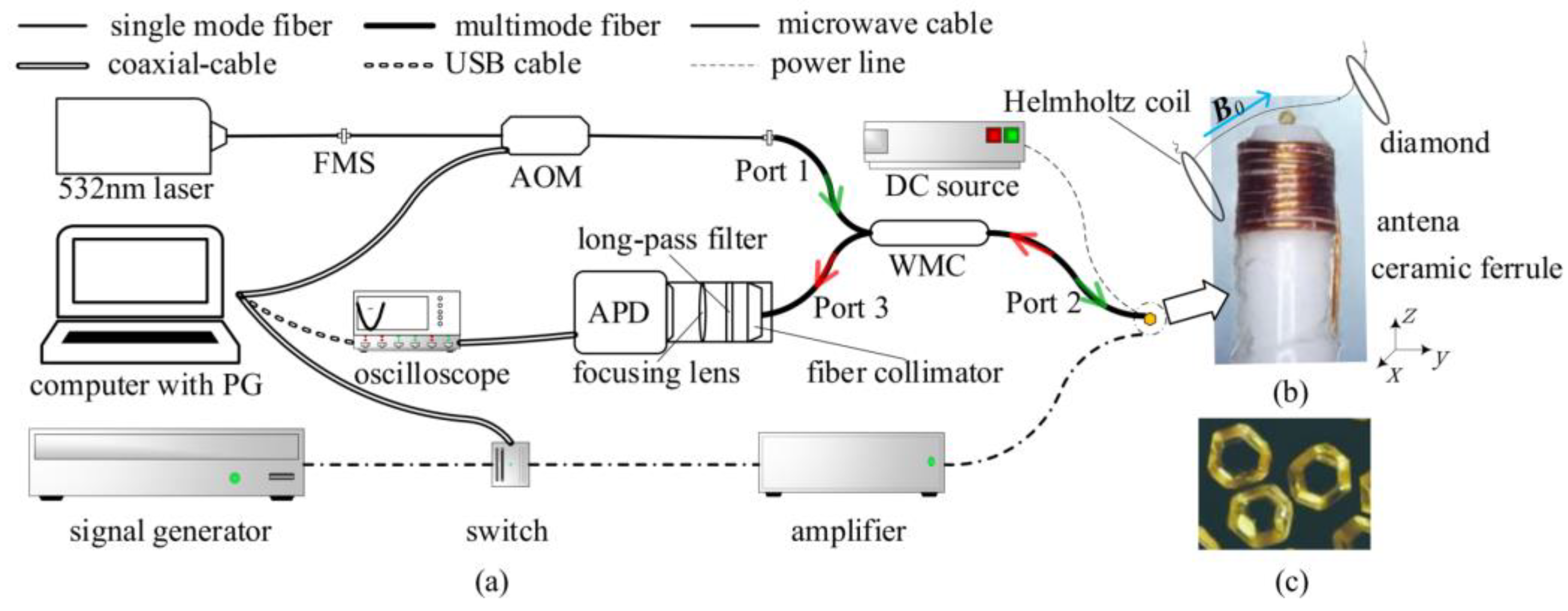
Abstract
:1. Introduction
2. Materials and Methods
3. Experiments and Discussion
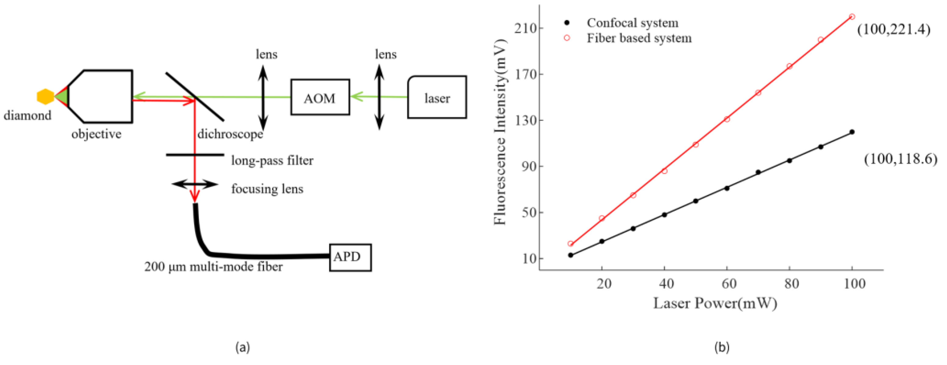
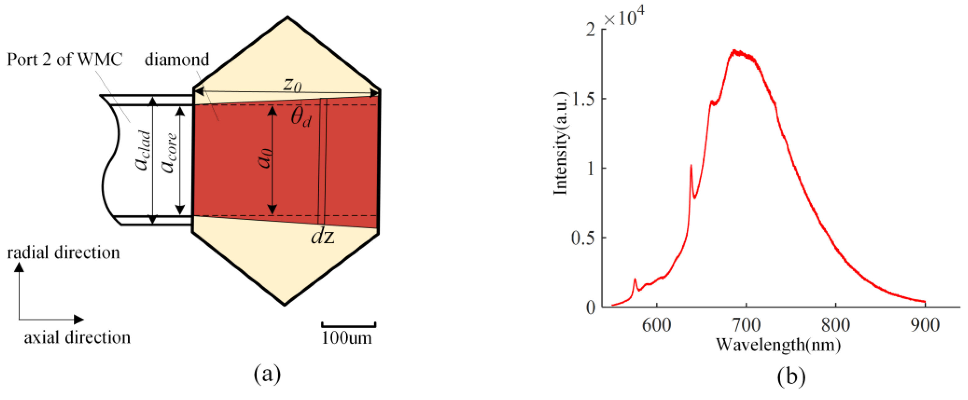
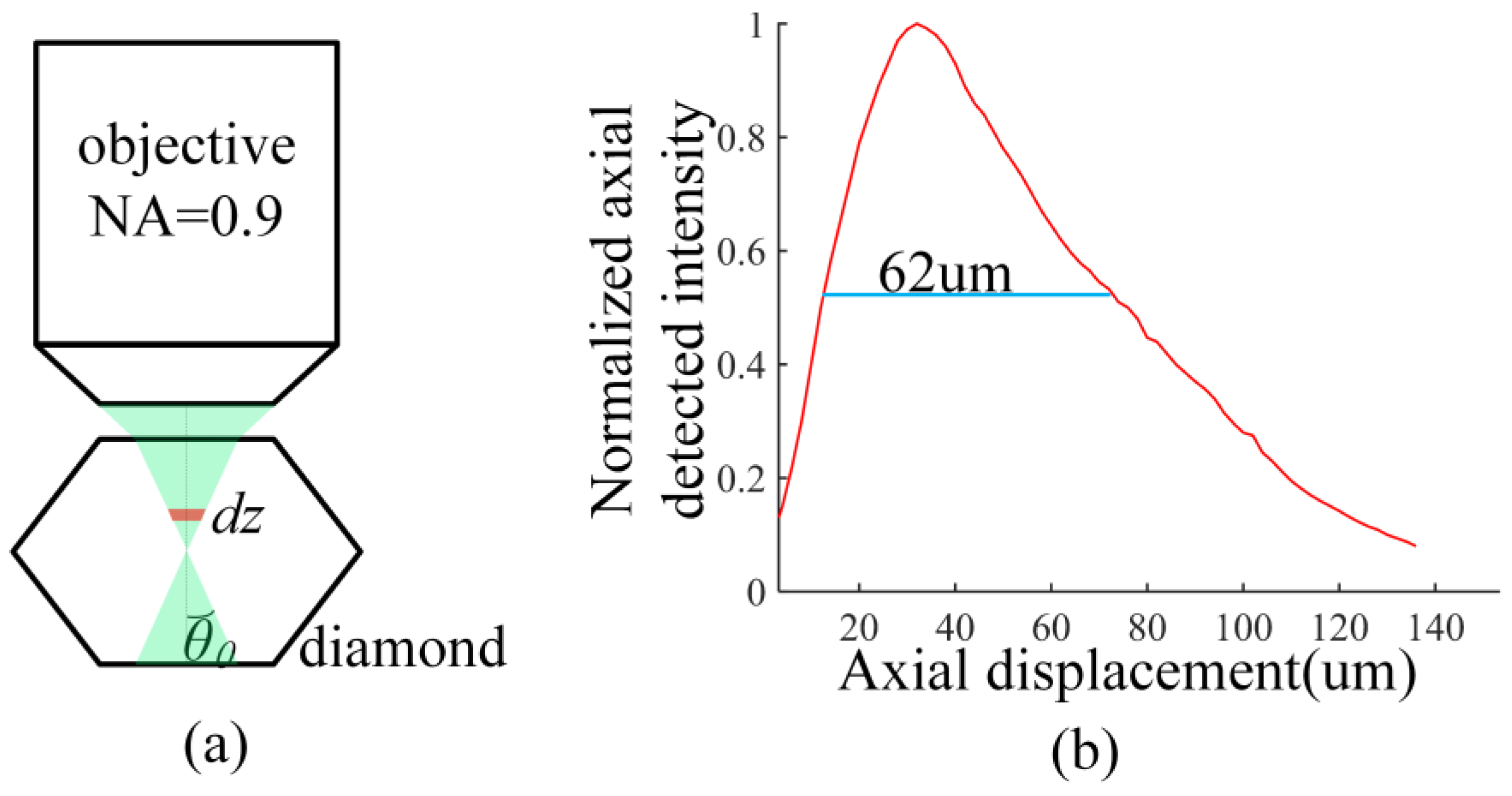
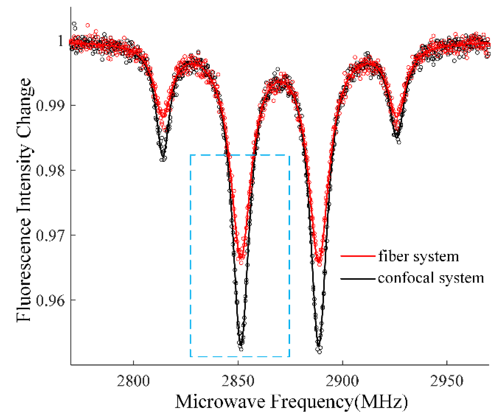
3.1. Optical Interrogation of NV Centers in Diamond
3.2. Sensitivity Analysis
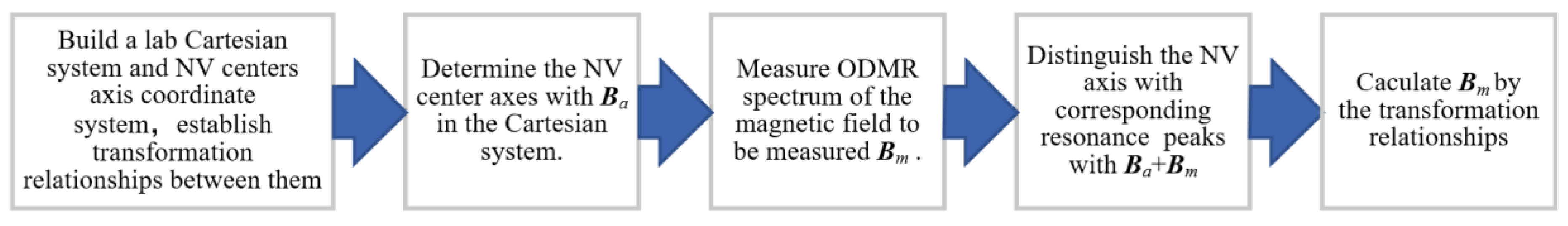
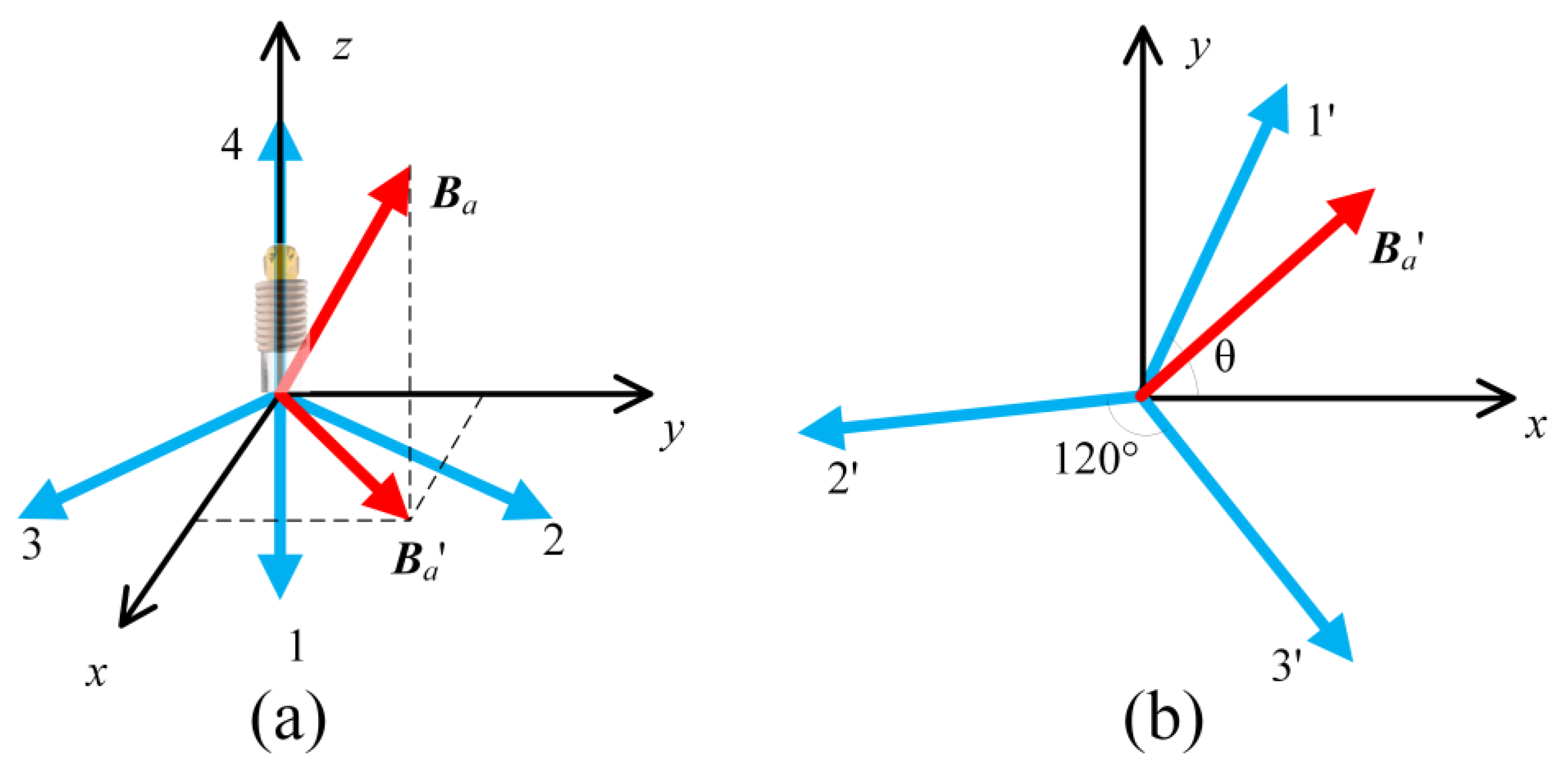
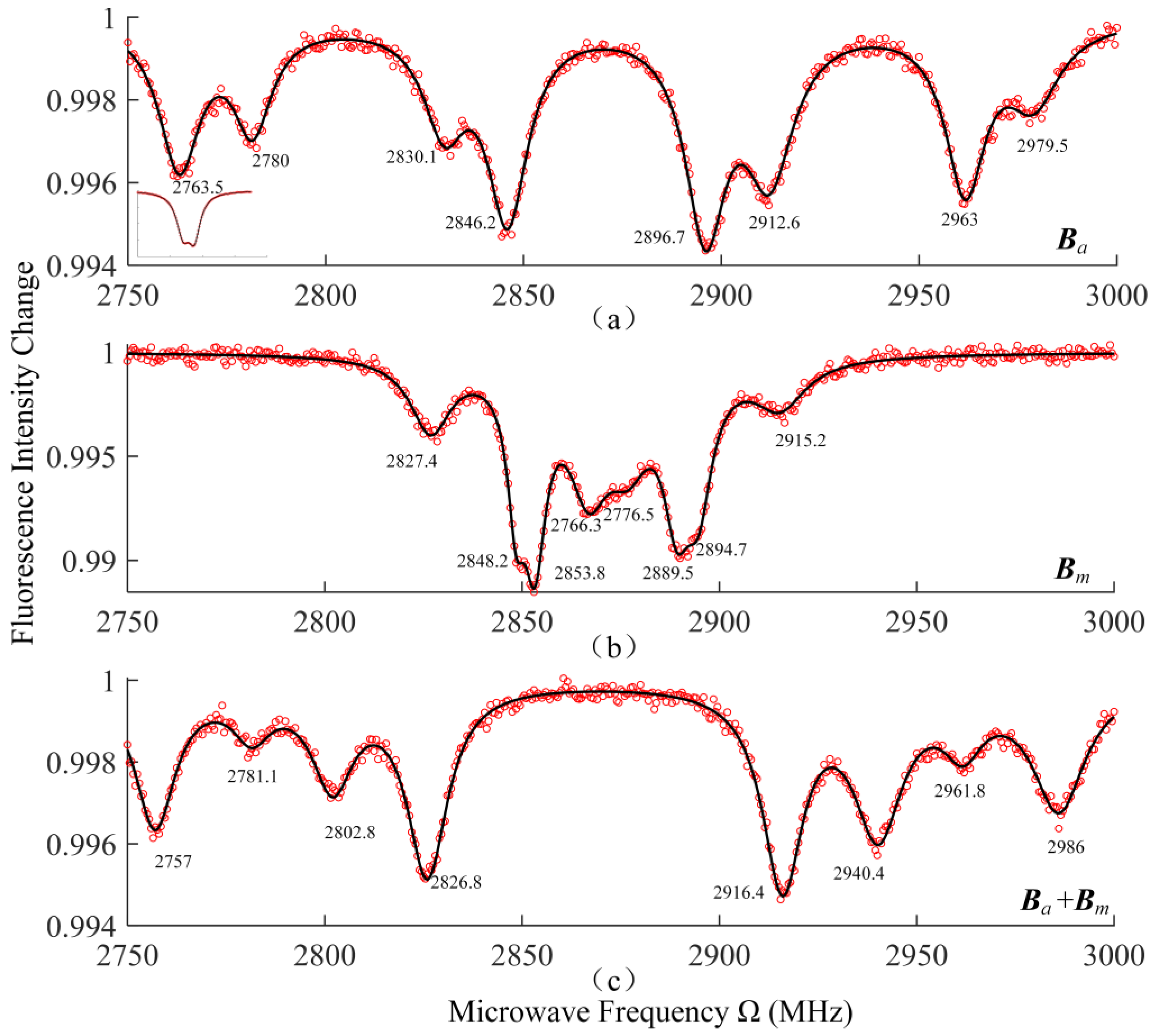
3.3. Vector Magnetic Field Measurement
4. Conclusions
Author Contributions
Funding
Data Availability Statement
Acknowledgments
Conflicts of Interest
References
- Childress, L.; Dutt, M.V.G.; Taylor, J.M.; Zibrov, A.S.; Jelezko, F.; Wrachtrup, J.; Hemmer, P.R.; Lukin, M.D. Coherent dynamics of coupled electron and nuclear spin qubits in diamond. Science 2006, 314, 281–285. [Google Scholar] [CrossRef] [PubMed] [Green Version]
- Degen, C.L.; Reinhard, F.; Cappellaro, P. Quantum sensing. Rev. Mod. Phys. 2017, 89, 39. [Google Scholar] [CrossRef] [Green Version]
- Gaebel, T.; Domhan, M.; Popa, I.; Wittmann, C.; Neumann, P.; Jelezko, F.; Rabeau, J.R.; Stavrias, N.; Greentree, A.D.; Prawer, S.; et al. Room-temperature coherent coupling of single spins in diamond. Nat. Phys. 2006, 2, 408–413. [Google Scholar] [CrossRef] [Green Version]
- Glenn, D.R.; Bucher, D.B.; Lee, J.; Lukin, M.D.; Park, H.; Walsworth, R.L. High-resolution magnetic resonance spectroscopy using a solid-state spin sensor. Nature 2018, 555, 351–354. [Google Scholar] [CrossRef] [PubMed] [Green Version]
- Zhang, J.X.; Yuan, H.; Zhang, N.; Xu, L.X.; Bian, G.D.; Fan, P.C.; Li, M.X.; Zhan, Z.; Yu, K. A Modified Spin Pulsed Readout Method for NV Center Ensembles Reducing Optical Noise. IEEE Trans. Instrum. Meas. 2020, 69, 4370–4378. [Google Scholar] [CrossRef]
- Zhang, N.; Yuan, H.; Zhang, C.; Xu, L.X.; Zhang, J.X.; Bian, G.D.; Fan, P.C.; Yuan, H.D.; Fang, J.C. Microwave Field Uniformity Impact on DC Magnetic Sensing With NV Ensembles in Diamond. IEEE Sens. J. 2019, 19, 451–456. [Google Scholar] [CrossRef]
- Le Sage, D.; Arai, K.; Glenn, D.R.; DeVience, S.J.; Pham, L.M.; Rahn-Lee, L.; Lukin, M.D.; Yacoby, A.; Komeili, A.; Walsworth, R.L. Optical magnetic imaging of living cells. Nature 2013, 496, 486–489. [Google Scholar] [CrossRef] [Green Version]
- Hall, L.T.; Beart, G.C.G.; Thomas, E.A.; Simpson, D.A.; McGuinness, L.P.; Cole, J.H.; Manton, J.H.; Scholten, R.E.; Jelezko, F.; Wrachtrup, J.; et al. High spatial and temporal resolution wide-field imaging of neuron activity using quantum NV-diamond. Sci. Rep. 2012, 2, 9. [Google Scholar] [CrossRef] [Green Version]
- Lee, M.; Jang, B.; Yoon, J.; Mathpal, M.C.; Lee, Y.; Kim, C.; Pane, S.; Nelson, B.J.; Lee, D. Magnetic imaging of a single ferromagnetic nanowire using diamond atomic sensors. Nanotechnology 2018, 29, 7. [Google Scholar] [CrossRef]
- Ku, M.J.H.; Zhou, T.X.; Li, Q.; Shin, Y.J.; Shi, J.K.; Burch, C.; Anderson, L.E.; Pierce, A.T.; Xie, Y.L.; Hamo, A.; et al. Imaging viscous flow of the Dirac fluid in graphene. Nature 2020, 583, 537–541. [Google Scholar] [CrossRef] [PubMed]
- Zhou, L.Q.; Patel, R.L.; Frangeskou, A.C.; Nikitin, A.; Green, B.L.; Breeze, B.G.; Onoda, S.; Isoya, J.; Morley, G.W. Imaging Damage in Steel Using a Diamond Magnetometer. Phys. Rev. Appl. 2021, 15, 10. [Google Scholar] [CrossRef]
- Li, S.; Bai, D.B.; Capelli, M.; Sun, Q.; Afshar, V.S.; Simpson, D.A.; Foster, S.; Ebendorff-Heidepriem, H.; Gibson, B.C.; Greentree, A.D. Preferential coupling of diamond NV centres in step-index fibres. Opt. Express 2021, 29, 14425–14437. [Google Scholar] [CrossRef]
- Zhang, S.C.; Dong, Y.; Du, B.; Lin, H.B.; Li, S.; Zhu, W.; Wang, G.Z.; Chen, X.D.; Guo, G.C.; Sun, F.W. A robust fiber-based quantum thermometer coupled with nitrogen-vacancy centers. Rev. Sci. Instrum. 2021, 92, 11. [Google Scholar] [CrossRef]
- Lanin, A.A.; Fedotov, I.V.; Ermakova, Y.G.; Sidorov-Biryukov, D.A.; Fedotov, A.B.; Hemmer, P.; Belousov, V.V.; Zheltikov, A.M. Fiber-optic electron-spin-resonance thermometry of single laser-activated neurons. Opt. Lett. 2016, 41, 5563–5566. [Google Scholar] [CrossRef] [PubMed]
- Guo, Z.; Chen, G.; Gu, B.; He, W.; Jiang, H.; Wang, H.; Du, G. Microwave Field Imaging of Stripline Chip Based on Nitrogen-Vacancy Center Ensembles in Diamond. Acta Electron. Sin. 2020, 48, 2258–2262. [Google Scholar]
- Zheng, D.D.; Ma, Z.M.; Guo, W.J.; Niu, L.M.; Wang, J.Q.; Chai, X.H.; Li, Y.J.; Sugawara, Y.; Yu, C.; Shi, Y.B.; et al. A hand-held magnetometer based on an ensemble of nitrogen-vacancy centers in diamond. J. Phys. D-Appl. Phys. 2020, 53, 6. [Google Scholar] [CrossRef]
- Webb, J.L.; Clement, J.D.; Troise, L.; Ahmadi, S.; Johansen, G.J.; Huck, A.; Andersen, U.L. Nanotesla sensitivity magnetic field sensing using a compact diamond nitrogen-vacancy magnetometer. Appl. Phys. Lett. 2019, 114, 5. [Google Scholar] [CrossRef] [Green Version]
- Liu, X.D.; Cui, J.M.; Sun, F.W.; Song, X.R.; Feng, F.P.; Wang, J.F.; Zhu, W.; Lou, L.R.; Wang, G.Z. Fiber-integrated diamond-based magnetometer. Appl. Phys. Lett. 2013, 103, 4. [Google Scholar] [CrossRef]
- Liebermeister, L.; Petersen, F.; Munchow, A.V.; Burchardt, D.; Hermelbracht, J.; Tashima, T.; Schell, A.W.; Benson, O.; Meinhardt, T.; Krueger, A.; et al. Tapered fiber coupling of single photons emitted by a deterministically positioned single nitrogen vacancy center. Appl. Phys. Lett. 2014, 104, 4. [Google Scholar] [CrossRef] [Green Version]
- Duan, D.W.; Kavatamane, V.K.; Arumugam, S.R.; Rahane, G.; Tzeng, Y.K.; Chang, H.C.; Sumiya, H.; Onoda, S.; Isoya, J.; Balasubramanian, G. Enhancing fluorescence excitation and collection from the nitrogen-vacancy center in diamond through a micro-concave mirror. Appl. Phys. Lett. 2018, 113, 5. [Google Scholar] [CrossRef] [Green Version]
- Kuwahata, A.; Kitaizumi, T.; Saichi, K.; Sato, T.; Igarashi, R.; Ohshima, T.; Masuyama, Y.; Iwasaki, T.; Hatano, M.; Jelezko, F.; et al. Magnetometer with nitrogen-vacancy center in a bulk diamond for detecting magnetic nanoparticles in biomedical applications. Sci. Rep. 2020, 10, 9. [Google Scholar] [CrossRef] [PubMed] [Green Version]
- Fedotov, I.V.; Doronina-Amitonova, L.V.; Voronin, A.A.; Levchenko, A.O.; Zibrov, S.A.; Sidorov-Biryukov, D.A.; Fedotov, A.B.; Velichansky, V.L.; Zheltikov, A.M. Electron spin manipulation and readout through an optical fiber. Sci. Rep. 2014, 4, 6. [Google Scholar] [CrossRef] [PubMed] [Green Version]
- Chen, G.B.; He, W.H.; Dong, M.M.; Zhao, Y.; Du, G.X. Nitrogen-Vacancy Axis Orientation Measurement in Diamond Micro-Crystal for Tunable RF Vectorial Field Sensing. IEEE Sens. J. 2020, 20, 2440–2445. [Google Scholar] [CrossRef]
- Li, C.S.; Sun, L.; Yang, S.M.; Zhang, L.C.; Wu, C.H.; Jiang, Z.D. Three-dimensional characterization and modeling of diamond electroplated grinding wheels. Int. J. Mech. Sci. 2018, 144, 553–563. [Google Scholar] [CrossRef]
- Barry, J.F.; Schloss, J.M.; Bauch, E.; Turner, M.J.; Hart, C.A.; Pham, L.M.; Walsworth, R.L. Sensitivity optimization for NV-diamond magnetometry. Rev. Mod. Phys. 2020, 92, 68. [Google Scholar] [CrossRef]
- Siyushev, P.; Kaiser, F.; Jacques, V.; Gerhardt, I.; Bischof, S.; Fedder, H.; Dodson, J.; Markham, M.; Twitchen, D.; Jelezko, F.; et al. Monolithic diamond optics for single photon detection. Appl. Phys. Lett. 2010, 97, 3. [Google Scholar] [CrossRef] [Green Version]
- Doronina-Amitonova, L.V.; Fedotov, I.V.; Ivashkina, O.I.; Zots, M.A.; Fedotov, A.B.; Anokhin, K.V.; Zheltikov, A.M. Enhancing the locality of optical interrogation with photonic-crystal fibers. Appl. Phys. Lett. 2012, 101, 4. [Google Scholar] [CrossRef] [Green Version]
- Martinez-Corral, M.; Caballero, M.T.; Ibanez-Lopez, C.; Sarafis, V. Optical sectioning by two-pinhole confocal fluorescence microscopy. Micron 2003, 34, 313–318. [Google Scholar] [CrossRef] [PubMed] [Green Version]
- Rondin, L.; Tetienne, J.P.; Hingant, T.; Roch, J.F.; Maletinsky, P.; Jacques, V. Magnetometry with nitrogen-vacancy defects in diamond. Rep. Prog. Phys. 2014, 77, 26. [Google Scholar] [CrossRef] [Green Version]
- Jensen, K.; Acosta, V.M.; Jarmola, A.; Budker, D. Light narrowing of magnetic resonances in ensembles of nitrogen-vacancy centers in diamond. Phys. Rev. B 2013, 87, 10. [Google Scholar] [CrossRef] [Green Version]
- Vershovskii, A.K.; Dmitriev, A.K. Micro-Scale Three-Component Quantum Magnetometer Based on Nitrogen-Vacancy Color Centers in Diamond Crystal. Tech. Phys. Lett. 2015, 41, 393–396. [Google Scholar] [CrossRef]


Disclaimer/Publisher’s Note: The statements, opinions and data contained in all publications are solely those of the individual author(s) and contributor(s) and not of MDPI and/or the editor(s). MDPI and/or the editor(s) disclaim responsibility for any injury to people or property resulting from any ideas, methods, instructions or products referred to in the content. |
© 2023 by the authors. Licensee MDPI, Basel, Switzerland. This article is an open access article distributed under the terms and conditions of the Creative Commons Attribution (CC BY) license (https://creativecommons.org/licenses/by/4.0/).
Share and Cite
Zhao, M.; Lin, Q.; Meng, Q.; Shan, W.; Zhu, L.; Chen, Y.; Liu, T.; Zhao, L.; Jiang, Z. All Fiber Vector Magnetometer Based on Nitrogen-Vacancy Center. Nanomaterials 2023, 13, 949. https://doi.org/10.3390/nano13050949
Zhao M, Lin Q, Meng Q, Shan W, Zhu L, Chen Y, Liu T, Zhao L, Jiang Z. All Fiber Vector Magnetometer Based on Nitrogen-Vacancy Center. Nanomaterials. 2023; 13(5):949. https://doi.org/10.3390/nano13050949
Chicago/Turabian StyleZhao, Man, Qijing Lin, Qingzhi Meng, Wenjun Shan, Liangquan Zhu, Yao Chen, Tao Liu, Libo Zhao, and Zhuangde Jiang. 2023. "All Fiber Vector Magnetometer Based on Nitrogen-Vacancy Center" Nanomaterials 13, no. 5: 949. https://doi.org/10.3390/nano13050949