Article

Construction of Built-In Electric Field in TiO2@Ti2O3 Core-Shell Heterojunctions toward Optimized Photocatalytic Performance

1
State Key Laboratory Base for Eco-Chemical Engineering, College of Chemical Engineering, Qingdao University of Science and Technology, Qingdao 266042, China
2
Shandong Provincial Key Laboratory of Molecular Engineering, School of Chemistry and Chemical Engineering, Qilu University of Technology (Shandong Academy of Sciences), Jinan 250353, China
3
School of Chemistry and Pharmaceutical Engineering, Shandong First Medical University & Shandong Academy of Medical Sciences, Jinan 250117, China
*
Authors to whom correspondence should be addressed.
Nanomaterials 2023, 13(14), 2125; https://doi.org/10.3390/nano13142125
Submission received: 1 June 2023 / Revised: 12 July 2023 / Accepted: 18 July 2023 / Published: 21 July 2023
(This article belongs to the Special Issue Synthesis of TiO2 Nanoparticles and Their Catalytic Activity)

Abstract

:
A series of Ti2O3@TiO2 core-shell heterojunction composite photocatalysts with different internal electric fields were synthesized using simple heat treatment methods. The synthesized Ti2O3@TiO2 core-shell heterojunction composites were characterized by means of SEM, XRD, PL, UV–Vis, BET, SPV, TEM and other related analytical techniques. Tetracycline (TC) was used as the degradation target to evaluate the photocatalytic performance of the synthesized Ti2O3@TiO2 core-shell heterojunction composites. The relevant test results show that the photocatalytic performance of the optimized materials has been significantly enhanced compared to Ti2O3, while the photocatalytic degradation rate has increased from 28% to 70.1%. After verification via several different testing and characterization techniques, the excellent catalytic performance is attributed to the efficient separation efficiency of the photogenerated charge carriers derived from the built-in electric field formed between Ti2O3 and TiO2. When the recombination of electrons and holes is occupied, more charges are generated to reach the surface of the photocatalyst, thereby improving the photocatalytic degradation efficiency. Thus, this work provides a universal strategy to enhance the photocatalytic performance of Ti2O3 by coupling it with TiO2 to build an internal electric field.

1. Introduction

Tetracycline (TC) has stable properties due to its four-complex benzene cycloalkyl groups [1,2]. It is highly susceptible to accumulation in the environment, and it is a difficult-to-degrade organic pollutant. Tetracycline (TC) in the environment is persistent, easy to accumulate, and difficult to degrade, which causes serious harm to the food chain and human health [3,4]. In addition, due to its long application, drug resistance is a serious concern. It can be absorbed from the gastrointestinal tract, albeit not completely. About 60%~70% of the dose is residual in the environment. Therefore, the long-term residue of TC in the aquatic environment harms human health and the ecological environment. To alleviate this serious situation, applying photocatalysis technology to the degradation of water pollutants as soon as possible will greatly help with the purification of the water environment [5,6]. Compared with traditional chemical, physical, and biological technologies, semiconductor photocatalytic technology can efficiently degrade organic pollutants in wastewater, such as antibiotic wastewater, into small-molecule substances [7,8,9].
As the ninth most abundant element on Earth, titanium has been widely studied for its high thermal stability, low cost, and light-responsive ability in metal oxide composites such as titanium dioxide (TiO2) [10,11,12]. TiO2 can be stimulated by light to produce strong oxidizing h+ and strong reducing e, which makes TiO2 highly efficient in terms of its photocatalytic performance [13,14]. However, due to its inherent large bandgap (≈3 eV), typical titanium dioxide only responds to ultraviolet radiation with a wavelength of <378 nm [15,16,17]. In the past few decades, researchers have considerably reduced the bandgap to achieve titanium dioxide absorption of solar energy in the visible spectral range [18]. Research in the literature confirms that titanium dioxide’s bandgap width can be reduced to 1.5 eV, while its optical response can be extended to 800 nm, achieving a utilization rate of 40% for total solar energy [19]. However, to design an efficient full-spectrum solar converter with high solar energy utilization, further modification of titanium oxide is needed to reduce the bandgap to less than 0.5 eV.
Magnéli phase titanium oxides were only identified as conductive compounds in the 1950s, with the general formula TinO2n−1 (3 < n < 10). This non-stoichiometric semiconductor titanium oxide, which contains structural vacancies in both the titanium and oxygen sublattices, exhibits excellent photocatalytic performance. Due to the limitations of the methods used to manufacture Magnéli phase materials, it is difficult to prepare individual pure phases [20,21]. Therefore, the Magnéli phase materials synthesized by heating TiO2 or Ti at different temperatures typically contain mixed phases. In addition, the reliability of the electrical and chemical properties of the phases obtained through separation methods is relatively low. Even the most common methods (such as lame synthesis methods, both electrochemical and chemical) for synthesizing titanium suboxides still have many problems, such as the low active surface of the obtained material and the difficulty in adjusting the size and structure. For example, processing must be carried out in a high-temperature and oxygen-free atmosphere. In addition, even at temperatures ranging from 425 to 525 °C, TinO2n−1 is unstable and decomposes into various upper structures. However, the enhanced part of the photocatalytic performance with regard to photocatalytic degradation comes from the nanostructures on the surface of bulk titanium suboxides. Ti3+ ions play a significant role in reducing the bandgap and effectively boosting the adsorption and activation of reactants, which markedly enhances the light-responsive ability [22]. The relatively small bandgap of Ti2O3 enables it to absorb solar energy within the full spectral range [23,24]. In addition, Ti2O3 is one of the most representative examples of the Mott insulation system, and its metal–insulator transition characteristics are derived from the electronic correlation effect [25,26]. Due to its narrow bandgap, Ti2O3 exhibits high theoretical photocurrent density and high carrier mobility. After modification, the light absorption ability of traditional Ti2O3 can be further enhanced. Among many methods, constructing an internal electric field at the interface of the photocatalysts as a driving force for charge separation is considered an efficient method for achieving maximum carrier separation and driving target surface reactions in photocatalytic systems [27]. Specifically, photogenerated electrons will undergo reverse transfer driven by an electric field, greatly accelerating the separation of electron–hole pairs [28,29]. For example, Cui et al. constructed an internal electric field by preparing p–n homojunction perovskite solar cells, which directionally promoted the transport of photogenerated carriers, greatly reducing the carrier recombination losses and improving the power conversion efficiency [30].
As titanium suboxides are usually prepared via heat treatment under an inert or reductive atmosphere, there is a demand for methods to prepare nanostructured titanium suboxides via hydrothermal or other methods. During these synthesis processes, the phase structure of the material is not easily controlled, making it even more difficult to construct controllable heterojunctions in an orderly manner. Research has shown that introducing TiO2 (anatase)-based symbionts into the low oxidation state structure can significantly improve the conductivity of the composite and the properties related to photoluminescence [31]. Therefore, in this work, we combined the TiO2 and Ti2O3 to construct an orderly core-shell heterojunction, creating an internal electric field. In addition, the band structures of Ti2O3@TiO2 heterojunctions were investigated by means of UV–Vis spectroscopy, the Mott–Schottky curve, and surface photovoltage (SPV). Constructing an internal electric field has been proven to promote the transfer efficiency of photogenerated charges and improve photocatalytic activity. The correlation between built-in electric fields and photocatalytic performance was revealed based on multiple test characterizations. The possible enhanced photocatalytic degradation mechanism of tetracycline (TC) was proposed. This work provides a simple and universal method for regulating the built-in electric fields in photocatalysts that can be applied to environmental pollution purification.

2. Materials and Methods

2.1. Chemicals

The Ti2O3 chemicals and tetracycline (TC) were purchased from Aladdin. The ethanol and Nafion solution were purchased from Sigma–Aldrich. Deionized water was used in the experiments. The materials used were all of analytical grade (99%) and had not undergone purification treatment.

2.2. Methods

Synthesis of the Ti2O3@TiO2 Heterojunction

The Ti2O3@TiO2 heterojunction was synthesized via a simple heat treatment method. First, using commercial Ti2O3 as the research object, a Ti2O3@TiO2 heterojunction system was constructed in an orderly fashion using heat treatment methods. Then, 1 g of Ti2O3 was dispersed in a porcelain boat. Program heating was used to raise the temperature at 2 °C min−1 from room temperature to different predetermined temperatures. The temperature was kept constant for 2 h and cooled to room temperature. The reaction conditions for the preparation of the TiO2@Ti2O3 heterojunction were explored. Reaction temperatures of 100 °C, 200 °C, 300 °C, 400 °C, 500 °C, 550 °C, 600 °C, and 700 °C were selected to explore the photocatalytic activity of TiO2@Ti2O3 toward TC decomposition. The prepared catalysts were named Ti2O3-100, Ti2O3-200, Ti2O3-300, Ti2O3-400, Ti2O3-500, Ti2O3-550, Ti2O3-600, and Ti2O3-700, respectively.

2.3. Characterizations

The crystalline phase structures of the Ti2O3@TiO2 samples were determined via X-ray diffraction (XRD) (Rigaku, Tokyo, Japan) with Cu Kα irradiation. Field emission scanning electron microscopy (SEM) (HITACHI, SU8010, Tokyo, Japan) and transmission electron microscopy (TEM) (JEM-ARM200F, Tokyo, Japan) were performed to reveal the surface topography of the Ti2O3@TiO2 samples. The adsorption isotherm of the Ti2O3@TiO2 samples was used to measure the specific surface area, and a pore size distribution analyzer (BET, Micromeritics, ASAP2460, Norcross, GA, USA) with N2 as the adsorption medium was used in combination with analysis via the Brunauer–Emmett–Teller (BET) method. The carrier recombination was evaluated based on the photoluminescence (PL) spectra (Edinburgh, Livingston, FLS 980, Scotland, UK) with using a Xenon lamp (excitation wavelength 375 nm). UV–Vis diffuse reflectance spectroscopy was used to analyze the spectral response range of the Ti2O3@TiO2 (DRS, Shimadzu, SolidSpec-3700, Tokyo, Japan). The energy gap (Eg) of the Ti2O3@TiO2 and Ti2O3 was obtained via the Tauc plot method. Thermogravimetric analysis (TGA) was used to monitor the thermal stability performance of the Ti2O3@TiO2 and Ti2O3 on an SDT Q600 (TA Instruments, New Castle, DE, USA). The SPV transient was recorded using a tunable Nd:YAG laser (EKSPLA, NT 342/1/UVE) excited by pulses with a duration of 5 ns and wavelengths between 420 and 720 nm, and a sampling oscilloscope (GAGE, CS14200, sampling rate of 100 Mm/s) was used by applying logarithmic readings without averaging to avoid potential accuracy loss in a short period. An electrochemical station (CHI660E, Chenhua, Shanghai, China) with a conventional three-electrode system was employed to carry out the electrochemical measurements. The three-electrode system contained working, counter (carbon rod) and reference (Ag/AgCl) electrodes in 1 M KOH alkaline medium. The steps for making the working electrodes were as follows: 4 mg of catalysts was dispersed in 1 mL of mixed solution (water:ethanol = 3:1) before 10 μL was taken and added dropwise to the surface of 1 × 1 cm−2 ITO and then left to dry naturally.

2.4. Measurement of Photocatalytic Activity

The photocatalytic performances of the Ti2O3@TiO2 and Ti2O3 were mainly confirmed by examining the photocatalytic degradation under simulated visible light. First, 100 mg of catalyst was added to 100 mL of TC solution (5 mg/L). A mechanical stirrer was used to stir the solution with a speed range of 0–1500 rpm. Before irradiation, a 20 min dark reaction was performed to achieve adsorption–desorption equilibrium. Then, the reaction solution was irradiated using a 300 W Xenon lamp with AM 1.5 (the current was 1.8 A; PLS-SXE300D, Perfect Light, Beijing, China). During the photocatalytic reaction, 4 mL of the solution was withdrawn every 20 min and the concentration of TC was measured. Correspondingly, the absorbance of TC in the supernatant solution was measured at a detection wavelength of 357 nm using a UV–Vis spectrophotometer corresponding to the maximum adsorption for the solution. The photocatalytic activities of the Ti2O3@TiO2 and Ti2O3 were studied by analyzing the degradation curves of the tetracycline.

3. Results and Discussion

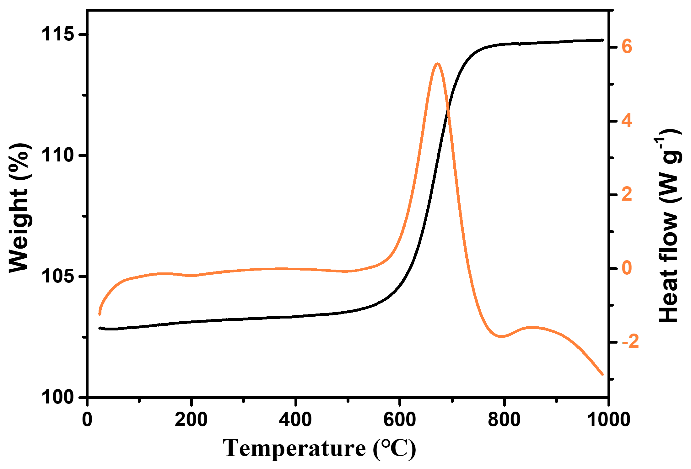
3.1. The Results of the TGA

To investigate the changes in the quality and heat flux of the materials at different temperatures, TG tests were conducted on the samples. From the results (Figure 1), it can be seen that when the temperature reaches above 500 °C, the material mass gradually increases, which is due to the gradual oxidation of Ti2O3 to form TiO2. When the temperature reaches 750 °C, the mass of the sample tends to stabilize. The sample undergoes phase transformation at different temperatures, so it is highly feasible to construct a Ti2O3@TiO2 heterojunction system in an orderly manner using heat treatment methods.
As shown in Figure 2, after treatment at different temperatures, the color of the Ti2O3 changed significantly, with the pure Ti2O3 turning black. When the temperature was below 600 °C, the color of the sample became lighter as the temperature increased. When the temperature was above 600 °C, the sample color turned yellow. Therefore, to further investigate the effect of temperature on the microstructures of the materials, scanning electron microscopy (SEM) was used to study the changes in the microstructure of the Ti2O3 under different heat treatment temperatures. Based on the results in Figure 1 and Figure 2, the Ti2O3, Ti2O3-400, Ti2O3-500, Ti2O3-550, Ti2O3-600, and Ti2O3-700 were selected for the SEM characterization.

3.2. The Results of the SEM and XRD Analyses

From the results in Figure 3, it can be seen that the Ti2O3 before heat treatment has an irregular 3D particle structure with a smooth surface. When the temperature is below 500 °C, there is no significant change in the microstructure and size of the sample. When the temperature reaches 550 °C, the surface roughness of the sample significantly increases and small particles are generated on the outer surface. As the temperature further increases, the outer particle diameter continuously increases and agglomeration occurs.
In order to investigate the crystal form changes in Ti2O3 after the heat treatment reaction, the samples were characterized by measn of XRD. As shown in Figure 4, the diffraction peaks detected at 23.8°, 33.0°, 34.8°, 40.2°, 48.8°, and 53.7° are related to the Ti2O3 phase (JCPDS No. 43-1033) and can be attributed to the (012), (104), (110), (113), (024), and (116) crystal planes, respectively [32]. When the heat treatment temperature reaches 400 °C, new diffraction peaks begin to appear at 27.4° (110) and 36.0° (101), which belong to the rutile phase TiO2 (JCPDS No. 21-1276) [33]. With the further increase in temperature, the diffraction peaks attributed to the rutile phase TiO2 further appear at 27.4° (110), 36.0° (101), 39.2° (200), 41.2° (111), 44.0° (210), 54.3° (211), 56.6° (220), and 64.1° (310), and the peak intensity also increases with the thermal treatment temperature. When the temperature reaches 600 °C, all the Ti2O3 is converted into the TiO2 rutile phase. In addition, no diffraction peaks of impurities are observed. Therefore, Ti2O3 gradually undergoes phase transition into TiO2 during the heat treatment process. Combining XRD and SEM shows that the Ti2O3-450, Ti2O3-500 and Ti2O3-550 are composed of Ti2O3 and TiO2, forming a core-shell heterojunction. The experimental results show that the progress of TiO2 conversion can be controlled by changing the heat treatment temperature, thereby achieving the orderly construction of a Ti2O3@TiO2 heterojunction system.

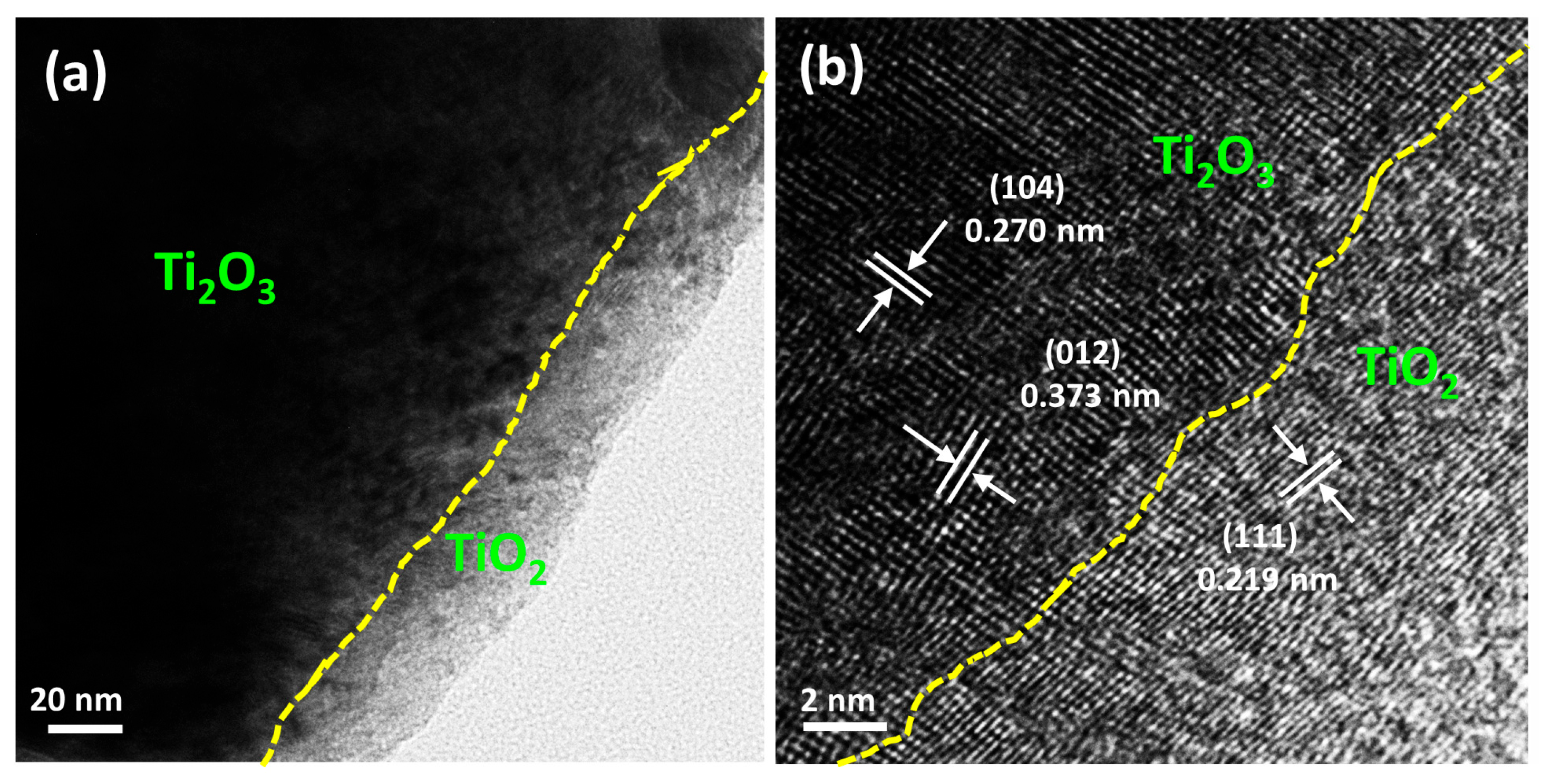
3.3. The Results of the TEM Analyses

In order to further investigate the microstructure and crystal plane changes of the Ti2O3-based samples during the high-temperature reaction, we conducted TEM testing on the Ti2O3 samples after high-temperature treatment at 550 °C. Figure 5a shows that after the high-temperature treatment, there are significant differences between the microstructure of the outer layer and the internal structure of the Ti2O3@TiO2 heterostructure, such as the particle accumulation and size. As shown in Figure 5b, electron diffraction can further indicate that the particulate matter comprises Ti2O3 and TiO2. The high-resolution transmission test results show that the lattice fringes are d = 0.27 nm and 0.373 nm, belonging to the (104) and (0.12) of Ti2O3, and d = 0.219 nm, belonging to the (111) of TiO2. The TEM results are consistent with the previous XRD and scanning test results, once again proving that the heat treatment method can construct Ti2O3@TiO2 heterojunctions.

3.4. The Results of the N2 Adsorption Analyses

N2 adsorption–desorption experiments were conducted to investigate the effects of different temperatures on the specific surface area and pore size of the composite materials. Figure 6a shows that the specific surface area of the Ti2O3-550 is the largest, approximately 0.796 m2/g, which is about 12 times that of the original Ti2O3 (approximately 0.067 m2/g). The pore volume of the Ti2O3 significantly increased from 0.000467 cm3/g to 0.0058 cm3/g (Ti2O3-550), demonstrating the reconstruction of the microstructure of the material during the transition from Ti2O3 to TiO2. In addition, in the Ti2O3@TiO2 heterojunction system, the Ti2O3-700 bulk phase has the highest content of TiO2, although its specific surface area is not the largest. This phenomenon proves that the expansion effect of the specific surface area in the system does not originate from the TiO2. Therefore, the research results indicate that the temperature has significant control over the microstructure of the system. In addition, from the pore size distribution map (Figure 6b), it can be seen that the pore size of the original Ti2O3 is mainly distributed around 37.5 nm and 50 nm. With the increase in the heat treatment temperature, the Ti2O3@TiO2 heterojunctions generate new pore structures in the bulk phase after retaining the original pore structure of the material, with the pore sizes mainly being concentrated in the range of 18–20 nm. The results suggest that the microstructure of the Ti2O3 did not undergo significant changes during the heat treatment process.

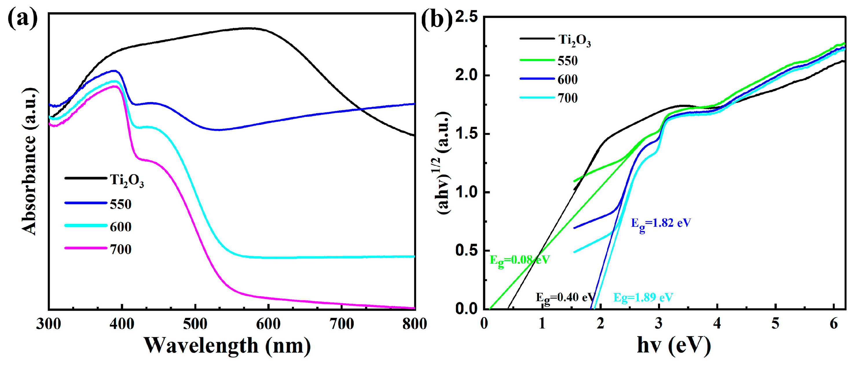
3.5. The Results of the UV–Vis Analyses

UV visible absorption spectroscopy was used to study the regulatory effect of the built-in electric field on the optical properties of the Ti2O3 and Ti2O3@TiO2 heterojunctions. As shown in Figure 7, both the Ti2O3 and Ti2O3@TiO2 heterojunctions exhibit strong absorption from 200 to 500 nm. It is worth noting that the Ti2O3-550 sample exhibits excellent absorption capacity throughout the entire process and significant tail absorption under the irradiation of visible light (λ > 600 nm). Compared with the as-received Ti2O3, the absorption ability of the Ti2O3-550 sample in the visible light absorption region remains unchanged, or even slightly enhanced. The existence of an internal electric field can promote the absorption ability of the Ti2O3-550 with regard to visible light. In addition, the bandgaps of the Ti2O3 and Ti2O3@TiO2 heterojunctions can be estimated using the formula of α hv = A ( hv Eg ) 1 2 (Eg is the bandgap energy, α is the absorption coefficient, A is a constant, v is the optical frequency, and h is the Planck constant) [34]. In the graph of photon energy, the bandgap energy value is the intersection point between the extended dashed line and the horizontal axis of the coordinate system (the horizontal axis value is hv = 1240/wavelength, while the vertical axis value is (α Hv) ½) [35,36]. As shown in Figure 7b, the calculated bandgaps of the pure Ti2O3 and Ti2O3-550, Ti2O3-600, and Ti2O3-700 are 0.4 eV, 0.08 eV, 1.82 eV, and 1.89 eV, respectively, indicating that the bandgaps of semiconductor materials can be effectively adjusted and optimized by constructing a reasonable internal electric field. Compared with other reported materials, the synthesized materials have relatively small bandgaps (Table 1).

3.6. The Results of the Optoelectronic Performance Analyses

Photoelectrochemical measurements in a typical three-electrode battery were used to study the electron generation and migration characteristics of the Ti2O3 and Ti2O3@TiO2 heterojunctions. As shown in Figure 8a, among the pure Ti2O3 and Ti2O3@TiO2 heterojunction systems, the Ti2O3-550 has the strongest photocurrent density, much higher than the original Ti2O3, confirming its excellent solar energy utilization ability. The above measurements intuitively prove that the material prepared at 550 °C has the best photoelectric performance. In addition, the relationship between the samples prepared at different heat treatment temperatures and the photocatalytic performance was systematically studied. The catalytic performance of the Ti2O3 and Ti2O3@TiO2 heterojunctions (Ti2O3-400, Ti2O3-500, Ti2O3-550, Ti2O3-600) under visible light was investigated using TC as the substrate. As shown in Figure 8b, after stirring under dark conditions for 20 min, the matrix adsorption–desorption equilibrium of all the samples was observed. The photocatalytic performance of the Ti2O3 and Ti2O3@TiO2 heterojunction composite materials was evaluated by measuring the degradation of the tetracycline in the sample under simulated visible light irradiation. From the results, it can be seen that Ti2O3 significantly enhances its ability to degrade tetracycline by constructing a Ti2O3@TiO2 heterojunction, with the degradation rate increasing from 28% to 70.1% (35.05 mg of tetracycline degraded/100 mg of photocatalyst). Compared with other reported materials, the synthesized materials have relatively good photocatalytic degradation efficiency (Table 2). As the temperature further increases, the catalytic efficiency decreases. The experimental results indicate that the excellent photocatalytic performance of the Ti2O3-550 can be attributed to the narrower bandgap, reasonable band structure, and larger specific surface area. More importantly, the proper construction of the heterojunction may result in the redistribution of the electron density to build an internal electric field in the Ti2O3@TiO2 and inhibit the recombination process of the electron–hole pairs. Therefore, by constructing heterojunctions reasonably and achieving precise regulation of the built-in electric fields, the photocatalytic activity of semiconductor materials can be optimized.

3.7. Discussion on the Photocatalytic Mechanism

In order to investigate the built-in electric field effect in the Ti2O3 and Ti2O3@TiO2 heterojunctions in depth, the surface photovoltage (SPV) was used to investigate the separation and migration process of the photogenerated charge carriers in the materials [48]. Figure 9a,b show that the SPV response signals of the original Ti2O3 and Ti2O3-400 were not detected. This may be due to the materials’ low separation efficiency or the high recombination efficiency of the photogenerated carriers. When the heat treatment temperature was further increased to 500 and 550 °C (Figure 9c,d), significant photovoltage response signals were observed at 275–400 nm for the Ti2O3-500 and Ti2O3-550, which can be attributed to the electronic transitions between the valence band and conduction band [49,50]. Moreover, the SPV response is positive, indicating that the upward energy band bends toward the surface/interface [51]. It can be clearly seen that the SPV response values have increased to 4.1 μV and 2.33 mV, respectively. This increase is caused by the built-in electric field constructed by the Ti2O3 and TiO2, which continuously adjusts with the composition. With the increase in the heat treatment temperature, the amount of TiO2 in the outer layer from the conversion of the Ti2O3 gradually increases and the built-in electric field effect is continuously enhanced. Thus, the separation of the photoexcited charge carriers is promoted, resulting in changes in the surface photovoltage. When the direction of the applied electric field is changed, there is no significant change in the photogenerated voltage of the Ti2O3-500 (Figure 9c), indicating that the direction of the built-in electric field of the Ti2O3-500 is opposite to the direction of the positive applied electric field. As shown in Figure 9d, the photogenerated voltage of the Ti2O3-550 significantly increases with the applied electric field. When the direction of the applied electric field is changed, the photogenerated voltage of the Ti2O3-500 is suppressed and reduced, indicating that the direction of the built-in electric field of the Ti2O3-550 is the same as the direction of the positive applied electric field. However, when the heat treatment temperature is increased to 600 °C (Figure 9e), the outer TiO2 content further increases. The SPV response of the Ti2O3-600 decreases to 0.75 mV, indicating that in the presence of excessive TiO2, the built-in electric field effect decreases and the separation of the photoexcited charge carriers and the recombination of the photogenerated electron–hole pairs are suppressed. In addition, the photogenerated voltage of the Ti2O3-600 increases significantly with the increase in the applied electric field. When the direction of the applied electric field changes, the photogenerated voltage of the Ti2O3-600 is suppressed and reduced, indicating that the direction of the built-in electric field of the Ti2O3-600 is the same as that of the positive applied electric field. Photogenerated charge carriers can recombine through radiation or non-radiation decay. Therefore, by comparing the changes in the SPV response with the heat treatment temperature in the Ti2O3 and Ti2O3@TiO2 heterojunctions, it can be inferred that the Ti2O3-550 has the best built-in electric field effect, which can effectively suppress non-radiative decay, allowing for the more effective separation of the photogenerated charge carriers and transport of the photogenerated electrons to the catalyst surface to facilitate the degradation of the tetracycline [52,53].
As shown in Figure 10, the slope of the straight-line portion of the Mott–Schottky curve of the Ti2O3 and Ti2O3@TiO2 heterojunctions (Ti2O3-500, Ti2O3-550, and Ti2O3-600) within the passivation zone is positive, indicating that the semiconductor film formed by the composite materials in this solution is an n-type semiconductor [54,55]. When the Ti2O3@TiO2 heterojunction is not in contact with the solution, the material’s Fermi energy level is higher than the solution’s chemical potential. When the Ti2O3@TiO2 heterojunction enters the solution, the carriers, i.e., electrons, in the bulk phase will spontaneously transfer from the high energy level to the low energy level, that is, from the side of the Ti2O3@TiO2 to the solution, to balance the Fermi energy levels [56]. A space charge layer is formed on one side of the Ti2O3@TiO2 film, causing the bulk phase to carry opposite charges to the solution. Excess charges are distributed within the space charge layer. Due to the lower concentration of electrons in the Ti2O3@TiO2 bulk phase compared to the solution, electrons continue to enter the solution. Therefore, in the surface area on the semiconductor side, electrons are consumed, leaving only positive charges. This process causes the energy ratio near the surface to be corrected internally in the semiconductor, resulting in the energy bands of the Ti2O3 and Ti2O3@TiO2 heterojunctions bending upwards in this region. As electrons continue to propagate, the energy band continues to bend upwards. If an external voltage is continuously applied to the Ti2O3 and Ti2O3@TiO2 heterojunctions, the charge distribution at the interface changes with the electron input and the band bending changes. When the electrons that flood into the space charge layer neutralize the excess positive charge there, the energy band of the semiconductor returns to the same level as when it was not in contact with the solution. At this point, the required voltage is the flat band voltage. Suppose there is a built-in electric field in the semiconductor. In that case, it will decrease the necessary external voltage required to determine the potential size of the built-in electric field.
As shown by the results, the flat band potentials of the Ti2O3, Ti2O3-500, Ti2O3-550, and Ti2O3-600 are −0.55 V, −0.49 V, −0.34 V, and −0.43 V, respectively. The results indirectly prove that in the Ti2O3@TiO2 heterojunction system, the built-in electric field of the Ti2O3-550 has the highest potential. In addition, the results of the Mott–Schottky curve indicate that the Ti2O3-550 has the highest carrier concentration, which is consistent with the conclusion obtained via the SPV. The Ti2O3-550 has a high Fermi energy level, which can endow the Ti2O3@TiO2 heterostructure with a more excellent electronic reservoir capability and accelerate the carrier separation and conversion.
These experimental results indicate that under visible light irradiation, the photocatalytic reaction of the Ti2O3@TiO2 heterojunction is direct photocatalysis, where electrons are excited by visible light from the valence band of the TiO2 to the transition band of the Ti2O3, which is lower than the conduction band of the TiO2. Then, electrons can easily transfer from the Ti (III) site to the adjacent Ti (IV) sites through the valence excitation process [22]. Under visible light irradiation, photogenerated holes are injected into the conduction band of the photocatalyst by the built-in electric field. Subsequently, electrons are captured to produce reactive substances and induce degradation reactions (Figure 11).

4. Conclusions

In summary, Ti2O3@TiO2 heterojunctions have been constructed via a sample heat treatment method as an efficient TC degradation system. The photocatalytic activity of the Ti2O3@TiO2 heterojunctions for TC degradation under visible light was investigated. Compared with the pure Ti2O3, the photocatalytic performance of the Ti2O3@TiO2 heterojunctions was significantly improved. After the heterojunction structure was constructed, the photodegradation rate increased from 28% to 70.1% (35.05 mg of tetracycline degraded/100 mg of photocatalyst). The relevant experimental results indicated that the excellent photocatalytic performance of the Ti2O3-550 can be attributed to the narrow bandgap and reasonable band structure derived from the built-in electric field. By using the SPV and Mott–Schottky methods, it was revealed that the construction of the heterojunctions in the Ti2O3@TiO2 resulted in the construction of an internal electric field, which suppressed the recombination process of the photogenerated electron–hole pairs. The most significant aspect here is that the built-in electric field can be controlled by changing the content of Ti2O3 and TiO2. Overall, this work provides a simple method to precisely regulate the built-in electric field and optimize the photocatalytic activity of semiconductor materials by reasonably constructing heterojunctions.

Author Contributions

Conceptualization, F.L., P.F. and H.C.; methodology, T.H. and L.G.; formal analysis, T.H., F.L., P.F. and H.C.; investigation, T.H. and L.G.; writing—original draft preparation, T.H.; writing—review and editing, F.L., P.F. and H.C.; visualization, P.F.; supervision, F.L., P.F. and H.C. All authors have read and agreed to the published version of the manuscript.

Funding

We gratefully acknowledge the support of the National Natural Science Foundation of China (22205124), the Shandong Province Natural Science Foundation (ZR2021QB070), Basic Research Projects for the Pilot Project of Integrating Science and Education and Industry of Qilu University of Technology (Shandong Academy of Sciences) (2023PY024), the Development Plan of the Youth Innovation Team in Colleges and Universities of Shandong Province, and Basic Research Projects for the Pilot Project of Integrating Science and Education and Industry of Qilu University of Technology (Shandong Academy of Sciences) (2023PX108).

Data Availability Statement

Not applicable.

Conflicts of Interest

The authors declare no conflict of interest.

References

  1. Wu, S.; Hu, H.; Lin, Y.; Zhang, J.; Hu, Y.H. Visible light photocatalytic degradation of tetracycline over TiO2. Chem. Eng. J. 2020, 382, 122842. [Google Scholar] [CrossRef]
  2. Xiao, Z.-J.; Feng, X.-C.; Shi, H.-T.; Zhou, B.-Q.; Wang, W.-Q.; Ren, N.-Q. Why the cooperation of radical and non-radical pathways in PMS system leads to a higher efficiency than a single pathway in tetracycline degradation. J. Hazard. Mater. 2022, 424, 127247. [Google Scholar] [CrossRef] [PubMed]
  3. Zhang, Q.; Jiang, L.; Wang, J.; Zhu, Y.; Pu, Y.; Dai, W. Photocatalytic degradation of tetracycline antibiotics using three-dimensional network structure perylene diimide supramolecular organic photocatalyst under visible-light irradiation. Appl. Catal. B Environ. 2020, 277, 119122. [Google Scholar] [CrossRef]
  4. Li, R.; Zhang, Y.; Deng, H.; Zhang, Z.; Wang, J.J.; Shaheen, S.M.; Xiao, R.; Rinklebe, J.; Xi, B.; He, X.; et al. Removing tetracycline and Hg(II) with ball-milled magnetic nanobiochar and its potential on polluted irrigation water reclamation. J. Hazard. Mater. 2020, 384, 121095. [Google Scholar] [CrossRef]
  5. Guo, J.; Wang, L.; Wei, X.; Alothman, Z.A.; Albaqami, M.D.; Malgras, V.; Yamauchi, Y.; Kang, Y.; Wang, M.; Guan, W.; et al. Direct Z-scheme CuInS2/Bi2MoO6 heterostructure for enhanced photocatalytic degradation of tetracycline under visible light. J. Hazard. Mater. 2021, 415, 125591. [Google Scholar] [CrossRef]
  6. Yang, D.; Xu, Y.; Pan, K.; Yu, C.; Wu, J.; Li, M.; Yang, F.; Qu, Y.; Zhou, W. Engineering surface oxygen vacancy of mesoporous CeO2 nanosheets assembled microspheres for boosting solar-driven photocatalytic performance. Chin. Chem. Lett. 2022, 33, 378–384. [Google Scholar] [CrossRef]
  7. Shen, Q.; Wei, L.; Bibi, R.; Wang, K.; Hao, D.; Zhou, J.; Li, N. Boosting photocatalytic degradation of tetracycline under visible light over hierarchical carbon nitride microrods with carbon vacancies. J. Hazard. Mater. 2021, 413, 125376. [Google Scholar] [CrossRef]
  8. Wang, Y.; Rao, L.; Wang, P.; Guo, Y.; Guo, X.; Zhang, L. Porous oxygen-doped carbon nitride: Supramolecular preassembly technology and photocatalytic degradation of organic pollutants under low-intensity light irradiation. Environ. Sci. Pollut. Res. 2019, 26, 15710–15723. [Google Scholar] [CrossRef]
  9. Fang, B.; Xing, Z.; Sun, D.; Li, Z.; Zhou, W. Hollow semiconductor photocatalysts for solar energy conversion. Adv. Powder Mater. 2022, 1, 100021. [Google Scholar] [CrossRef]
  10. Cui, Y.; Zheng, J.; Wang, Z.; Li, B.; Yan, Y.; Meng, M. Magnetic induced fabrication of core-shell structure Fe3O4@TiO2 photocatalytic membrane: Enhancing photocatalytic degradation of tetracycline and antifouling performance. J. Environ. Chem. Eng. 2021, 9, 106666. [Google Scholar] [CrossRef]
  11. Low, J.; Dai, B.; Tong, T.; Jiang, C.; Yu, J. In situ irradiated X-ray photoelectron spectroscopy investigation on a direct Z-scheme TiO2/CdS composite film photocatalyst. Adv. Mater. 2019, 31, 1802981. [Google Scholar] [CrossRef]
  12. Zhou, W.; Li, W.; Wang, J.-Q.; Qu, Y.; Yang, Y.; Xie, Y.; Zhang, K.; Wang, L.; Fu, H.; Zhao, D. Ordered mesoporous black TiO2 as highly efficient hydrogen evolution photocatalyst. J. Am. Chem. Soc. 2014, 136, 9280–9283. [Google Scholar] [CrossRef]
  13. Wang, W.; Han, Q.; Zhu, Z.; Zhang, L.; Zhong, S.; Liu, B. Enhanced photocatalytic degradation performance of organic contaminants by heterojunction photocatalyst BiVO4/TiO2/RGO and its compatibility on four different tetracycline antibiotics. Adv. Powder Technol. 2019, 30, 1882–1896. [Google Scholar] [CrossRef]
  14. Zhou, W.; Sun, F.; Pan, K.; Tian, G.; Jiang, B.; Ren, Z.; Tian, C.; Fu, H. Well-ordered large-pore mesoporous anatase TiO2 with remarkably high thermal stability and improved crystallinity: Preparation, characterization, and photocatalytic performance. Adv. Funct. Mater. 2011, 21, 1922–1930. [Google Scholar] [CrossRef]
  15. Guo, Q.; Zhou, C.; Ma, Z.; Yang, X. Fundamentals of TiO2 photocatalysis: Concepts, mechanisms, and challenges. Adv. Mater. 2019, 31, 1901997. [Google Scholar] [CrossRef]
  16. Li, Z.; Li, Z.; Zuo, C.; Fang, X. Application of nanostructured TiO2 in UV photodetectors: A review. Adv. Mater. 2022, 34, 2109083. [Google Scholar] [CrossRef]
  17. Schneider, J.; Matsuoka, M.; Takeuchi, M.; Zhang, J.; Horiuchi, Y.; Anpo, M.; Bahnemann, D.W. Understanding TiO2 photocatalysis: Mechanisms and materials. Chem. Rev. 2014, 114, 9919–9986. [Google Scholar] [CrossRef]
  18. Li, Z.; Li, H.; Wang, S.; Yang, F.; Zhou, W. Mesoporous black TiO2/MoS2/Cu2S hierarchical tandem heterojunctions toward optimized photothermal-photocatalytic fuel production. Chem. Eng. J. 2022, 427, 131830. [Google Scholar] [CrossRef]
  19. Boscaro, P.; Cacciaguerra, T.; Cot, D.; Fajula, F.; Hulea, V.; Galarneau, A. C, N-doped TiO2 monoliths with hierarchical macro-/mesoporosity for water treatment under visible light. Microporous Mesoporous Mater. 2019, 280, 37–45. [Google Scholar] [CrossRef]
  20. Jagminas, A.; Ramanavičius, S.; Jasulaitiene, V.; Šimėnas, M. Hydrothermal synthesis and characterization of nanostructured titanium monoxide films. RSC Adv. 2019, 9, 40727–40735. [Google Scholar] [CrossRef]
  21. Walsh, F.; Wills, R. The continuing development of Magnéli phase titanium sub-oxides and Ebonex® electrodes. Electrochim. Acta 2010, 55, 6342–6351. [Google Scholar] [CrossRef]
  22. Liu, H.; Yang, W.; Ma, Y.; Yao, J. Extended visible light response of binary TiO2-Ti2O3 photocatalyst prepared by a photo-assisted sol–gel method. Appl. Catal. A Gen. 2006, 299, 218–223. [Google Scholar] [CrossRef]
  23. Li, Y.; Zhu, Y.; Wang, M.; Zhao, M.; Xue, J.; Chen, J.; Wu, T. Recent Progress on Titanium Sesquioxide: Fabrication, Properties, and Applications. Adv. Funct. Mater. 2022, 32, 2203491. [Google Scholar] [CrossRef]
  24. Cai, Y.; Zhu, H.; Shi, Q.; Cheng, Y.; Chang, L.; Huang, W. Photothermal conversion of Ti2O3 film for tuning terahertz waves. iScience 2022, 25, 103661. [Google Scholar] [CrossRef] [PubMed]
  25. Li, Y.; Weng, Y.; Yin, X.; Yu, X.; Kumar, S.S.; Wehbe, N.; Wu, H.; Alshareef, H.N.; Pennycook, S.J.; Breese, M.B.; et al. Orthorhombic Ti2O3: A Polymorph-Dependent Narrow-Bandgap Ferromagnetic Oxide. Adv. Funct. Mater. 2018, 28, 1705657. [Google Scholar] [CrossRef]
  26. Chen, H.; Liang, J.; Li, L.; Zheng, B.; Feng, Z.; Xu, Z.; Luo, Y.; Liu, Q.; Shi, X.; Liu, Y.; et al. Ti2O3 nanoparticles with Ti3+ sites toward efficient NH3 electrosynthesis under ambient conditions. ACS Appl. Mater. Interfaces 2021, 13, 41715–41722. [Google Scholar] [CrossRef]
  27. Luo, Z.; Ye, X.; Zhang, S.; Xue, S.; Yang, C.; Hou, Y.; Xing, W.; Yu, R.; Sun, J.; Yu, Z.; et al. Unveiling the charge transfer dynamics steered by built-in electric fields in BiOBr photocatalysts. Nat. Commun. 2022, 13, 2230. [Google Scholar] [CrossRef]
  28. Zhang, H.; Chen, X.; Zhang, Z.; Yu, K.; Zhu, W.; Zhu, Y. Highly-crystalline triazine-PDI polymer with an enhanced built-in electric field for full-spectrum photocatalytic phenol mineralization. Appl. Catal. B Environ. 2021, 287, 119957. [Google Scholar] [CrossRef]
  29. Li, Z.; Wang, S.; Wu, J.; Zhou, W. Recent progress in defective TiO2 photocatalysts for energy and environmental applications. Renew. Sustain. Energy Rev. 2022, 156, 111980. [Google Scholar] [CrossRef]
  30. Cui, P.; Wei, D.; Ji, J.; Huang, H.; Jia, E.; Dou, S.; Wang, T.; Wang, W.; Li, M. Planar p–n homojunction perovskite solar cells with efficiency exceeding 21.3%. Nat. Energy 2019, 4, 150–159. [Google Scholar] [CrossRef]
  31. Ramanavicius, S.; Jagminas, A.; Ramanavicius, A. Gas sensors based on titanium oxides. Coatings 2022, 12, 699. [Google Scholar] [CrossRef]
  32. Chen, Y.; Mao, J. Sol–gel preparation and characterization of black titanium oxides Ti2O3 and Ti3O5. J. Mater. Sci. Mater. Electron. 2014, 25, 1284–1288. [Google Scholar] [CrossRef]
  33. Liu, X.; Li, X.; Zhu, L.; Wang, X. Preparation of molecularly imprinted Ag-TiO2 for photocatalytic removal of ethyl paraben. Environ. Sci. Pollut. Res. 2021, 29, 10308–10318. [Google Scholar] [CrossRef]
  34. Lai, M.T.L.; Lee, K.M.; Yang, T.C.K.; Lai, C.W.; Chen, C.Y.; Johan, M.R.; Juan, J.C. Highly effective interlayer expanded MoS2 coupled with Bi2WO6 as pn heterojunction photocatalyst for photodegradation of organic dye under LED white light. J. Alloys Compd. 2023, 953, 169834. [Google Scholar] [CrossRef]
  35. Thill, A.S.; Lobato, F.O.; Vaz, M.O.; Fernandes, W.P.; Carvalho, V.E.; Soares, E.A.; Poletto, F.; Teixeira, S.R.; Bernardi, F. Shifting the band gap from UV to visible region in cerium oxide nanoparticles. Appl. Surf. Sci. 2020, 528, 146860. [Google Scholar] [CrossRef]
  36. Jian, S.; Tian, Z.; Hu, J.; Zhang, K.; Zhang, L.; Duan, G.; Yang, W.; Jiang, S. Enhanced visible light photocatalytic efficiency of La-doped ZnO nanofibers via electrospinning-calcination technology. Adv. Powder Mater. 2022, 1, 100004. [Google Scholar] [CrossRef]
  37. Zhao, X.; Selcuk, S.; Selloni, A. Formation and stability of reduced TiOx layers on anatase TiO2 (101): Identification of a novel Ti2O3 phase. Phys. Rev. Mater. 2018, 2, 015801. [Google Scholar] [CrossRef]
  38. Velempini, T.; Prabakaran, E.; Pillay, K. Recent developments in the use of metal oxides for photocatalytic degradation of pharmaceutical pollutants in water—A review. Mater. Today Chem. 2021, 19, 100380. [Google Scholar] [CrossRef]
  39. Yu, X.; Li, Y.; Hu, X.; Zhang, D.; Tao, Y.; Liu, Z.; He, Y.; Haque, A.; Liu, Z.; Wu, T.; et al. Narrow bandgap oxide nanoparticles coupled with graphene for high performance mid-infrared photodetection. Nat. Commun. 2018, 9, 4299. [Google Scholar] [CrossRef] [Green Version]
  40. Abdel-Aziz, M.; Yahia, I.; Wahab, L.; Fadel, M.; Afifi, M. Determination and analysis of dispersive optical constant of TiO2 and Ti2O3 thin films. Appl. Surf. Sci. 2006, 252, 8163–8170. [Google Scholar] [CrossRef]
  41. Zhang, H.; Zhao, Y.; Chen, S.; Yu, B.; Xu, J.; Xu, H.; Haoa, L.; Liu, Z. Ti3+ self-doped TiOx@anatase core–shell structure with enhanced visible light photocatalytic activity. J. Mater. Chem. A 2013, 1, 6138–6144. [Google Scholar] [CrossRef]
  42. Thinley, T.; Yadav, S.; Prabagar, J.S.; Hosakote, A.; Kumar, K.A.; Shivaraju, H.P. Facile synthesis of MnTiO3/Ag/gC3N4 nanocomposite for photocatalytic degradation of tetracycline antibiotic and synthesis of ammonia. Mater. Today Proc. 2023, 75, 24–30. [Google Scholar] [CrossRef]
  43. Li, J.; Wang, B.; Pang, Y.; Sun, M.; Liu, S.; Fang, W.; Chen, L. Fabrication of 0D/1D Bi2MoO6/Bi/TiO2 heterojunction with effective interfaces for boosted visible-light photo-catalytic degradation of tetracycline. Colloids Surf. A Physicochem. Eng. Asp. 2022, 638, 128297. [Google Scholar] [CrossRef]
  44. Zhang, W.; Peng, Y.; Yang, Y.; Zhang, L.; Bian, Z.; Wang, H. Bismuth-rich strategy intensifies the molecular oxygen activation and internal electrical field for the photocatalytic degradation of tetracycline hydrochloride. Chem. Eng. J. 2021, 430, 132963. [Google Scholar] [CrossRef]
  45. Hosny, M.; Fawzy, M.; Eltaweil, A.S. Green synthesis of bimetallic Ag/ZnO@Biohar nanocomposite for photocatalytic degradation of tetracycline, antibacterial and antioxidant activities. Sci. Rep. 2022, 12, 7316. [Google Scholar] [CrossRef]
  46. Ma, C.; Wei, J.; Jiang, K.; Yang, Z.; Yang, X.; Yang, K.; Zhang, Y.; Zhang, C. Self-assembled micro-flowers of ultrathin Au/BiOCOOH nanosheets photocatalytic degradation of tetracycline hydrochloride and reduction of CO2. Chemosphere 2021, 283, 131228. [Google Scholar] [CrossRef]
  47. Feng, C.; Ouyang, X.; Deng, Y.; Wang, J.; Tang, L. A novel g-C3N4/g-C3N4−x homojunction with efficient interfacial charge transfer for photocatalytic degradation of atrazine and tetracycline. J. Hazard. Mater. 2023, 441, 129845. [Google Scholar] [CrossRef]
  48. Zhang, Y.; Xie, T.; Jiang, T.; Wei, X.; Pang, S.; Wang, X.; Wang, D. Surface photovoltage characterization of a ZnO nanowire array/CdS quantum dot heterogeneous film and its application for photovoltaic devices. Nanotechnology 2009, 20, 155707. [Google Scholar] [CrossRef]
  49. Hao, L.; Huang, H.; Guo, Y.; Zhang, Y. Multifunctional Bi2O2(OH)(NO3) nanosheets with {001} active exposing facets: Efficient photocatalysis, dye-sensitization, and piezoelectric-catalysis. ACS Sustain. Chem. Eng. 2018, 6, 1848–1862. [Google Scholar] [CrossRef]
  50. Kronik, L.; Shapira, Y. Surface photovoltage phenomena: Theory, experiment, and applications. Surf. Sci. Rep. 1999, 37, 1–206. [Google Scholar] [CrossRef]
  51. Chen, R.; Fan, F.; Dittrich, T.; Li, C. Imaging photogenerated charge carriers on surfaces and interfaces of photocatalysts with surface photovoltage microscopy. Chem. Soc. Rev. 2018, 47, 8238–8262. [Google Scholar] [CrossRef] [PubMed]
  52. Chen, R.; Fan, F.; Li, C. Unraveling charge-separation mechanisms in photocatalyst particles by spatially resolved surface photovoltage techniques. Angew. Chem. Int. Ed. 2022, 134, e202117567. [Google Scholar] [CrossRef]
  53. Zhang, Z.; Chen, X.; Zhang, H.; Liu, W.; Zhu, W.; Zhu, Y. A highly crystalline perylene imide polymer with the robust built-in electric field for efficient photocatalytic water oxidation. Adv. Mater. 2020, 32, 1907746. [Google Scholar] [CrossRef] [PubMed]
  54. Forghani, M.; McCarthy, J.; Cameron, A.P.; Davey, S.B.; Donne, S.W. Semiconductor properties of electrodeposited manganese dioxide for electrochemical capacitors: Mott-schottky analysis. J. Electrochem. Soc. 2021, 168, 020508. [Google Scholar] [CrossRef]
  55. Sun, B.; Zhou, W.; Li, H.; Ren, L.; Qiao, P.; Li, W.; Fu, H. Synthesis of particulate hierarchical tandem heterojunctions toward optimized photocatalytic hydrogen production. Adv. Mater. 2018, 30, 1804282. [Google Scholar] [CrossRef]
  56. Xu, D.; Zhang, S.-N.; Chen, J.-S.; Li, X.-H. Design of the Synergistic Rectifying Interfaces in Mott–Schottky Catalysts. Chem. Rev. 2022, 123, 1–30. [Google Scholar] [CrossRef]
Figure 1. Optical photos of the Ti2O3@TiO2 heterojunction at different heat treatment temperatures.
Nanomaterials 13 02125 g001
Figure 2. Optical photos of Ti2O3 at different heat treatment temperatures.
Nanomaterials 13 02125 g002
Figure 3. SEM images of Ti2O3 under different heat treatment temperatures: (a) Ti2O3; (b) Ti2O3-400; (c) Ti2O3-500; (d) Ti2O3-550; (e) Ti2O3-600; and (f) Ti2O3-700.
Nanomaterials 13 02125 g003
Figure 4. XRD spectra of Ti2O3, Ti2O3-100, Ti2O3-200, Ti2O3-300, Ti2O3-400, Ti2O3-450, Ti2O3-500, Ti2O3-550, Ti2O3-600, and Ti2O3-700.
Nanomaterials 13 02125 g004
Figure 5. (a,b) High-resolution TEM image of the Ti2O3-550 after high-temperature heat treatment.
Nanomaterials 13 02125 g005
Figure 6. (a) N2 adsorption–desorption isotherms of Ti2O3 at different heat treatment temperatures. (b) Pore size distribution curve of Ti2O3 at different heat treatment temperatures.
Nanomaterials 13 02125 g006
Figure 7. (a) Ultraviolet visible absorption spectra of the Ti2O3 and Ti2O3/TiO2 heterojunctions (Ti2O3-550, Ti2O3-600, and Ti2O3-700) and (b) the corresponding Kubelka–Munk conversion reflection spectra.
Nanomaterials 13 02125 g007
Figure 8. (a) Photogenerated current of the pure Ti2O3 and Ti2O3-400, Ti2O3-500, Ti2O3-550, and Ti2O3-600, and (b) the photocatalytic degradation performance of tetracycline.
Nanomaterials 13 02125 g008
Figure 9. Surface photovoltage (SPV) diagrams of the Ti2O3 and Ti2O3/TiO2 heterojunctions: (a) Ti2O3, (b) Ti2O3-400, (c) Ti2O3-500, (d) Ti2O3-550, and (e) Ti2O3-600.
Nanomaterials 13 02125 g009
Figure 10. Mott–Schottky diagrams of the Ti2O3 and Ti2O3/TiO2 heterojunctions: (a) Ti2O3, (b) Ti2O3-500, (c) Ti2O3-550, and (d) Ti2O3-600.
Nanomaterials 13 02125 g010
Figure 11. Schematic diagram of photocatalytic TC degradation over the Ti2O3@TiO2 heterojunctions.
Nanomaterials 13 02125 g011
Table 1. Comparison of the bandgaps of Ti2O3@TiO2 and other reported studies.
NumberTitanium-Based OxidesBandgapReferences
1α-Ti2O31–2 eV[37]
2csp-Ti2O31–2 eV[37]
3Anatase TiO23.2 eV[38]
4TiO23.3 eV[39]
5α-Ti2O3≈0.1 eV[23]
6TiO23.23 eV[40]
7Ti2O33.18 eV[40]
8T-723
(TiOx@anatase)
3.04 eV[41]
9T-810
(TiOx@anatase)
3.1 eV[41]
10Ti2O3@TiO20.08 eVThis work
Table 2. Comparison of the degradation efficiency of Ti2O3@TiO2 and other reported studies.
NumberTitanium-Based OxidesDegradation Efficiency (mg of Tetracycline Degraded/mg of Photocatalyst)References
1TiO25.67/20[1]
2MnTiO3/Ag/gC3N46.1/10[42]
3TBM0.05–50.66/10[8]
4Ag/ZnO@BC0.703/10[43]
5Bi3O4Br0.622/20[44]
6CTF-Bi2WO60.771/20[45]
72.0%Au/BiOCOOH1.13/20[46]
8g-C3N4−x/g-C3N41.56/50[47]
9Pristine TiO20.63/10[8]
10Ti2O3@TiO235.05/100This work
Disclaimer/Publisher’s Note: The statements, opinions and data contained in all publications are solely those of the individual author(s) and contributor(s) and not of MDPI and/or the editor(s). MDPI and/or the editor(s) disclaim responsibility for any injury to people or property resulting from any ideas, methods, instructions or products referred to in the content.

