Review

Perovskite-Based X-ray Detectors

1
Department of Photonics, National Cheng Kung University, Tainan 70101, Taiwan
2
Photovoltaic Technology Division, Green Energy & Environment Research Laboratories, Industrial Technology Research Institute, Tainan 71150, Taiwan
3
Department of Applied Materials and Optoelectronic Engineering, National Chi Nan University, Nantou 54561, Taiwan
4
Core Facility Center (CFC), National Cheng Kung University, Tainan 70101, Taiwan
5
Hierarchical Green-Energy Materials (Hi-GEM) Research Center, National Cheng Kung University, Tainan 70101, Taiwan
6
Program on Key Materials, Academy of Innovative Semiconductor and Sustainable Manufacturing, National Cheng Kung University, Tainan 70101, Taiwan
*
Authors to whom correspondence should be addressed.
Nanomaterials 2023, 13(13), 2024; https://doi.org/10.3390/nano13132024
Submission received: 1 June 2023 / Revised: 30 June 2023 / Accepted: 3 July 2023 / Published: 7 July 2023
(This article belongs to the Special Issue New Horizon in Perovskite Nanocrystals)

Abstract

:
X-ray detection has widespread applications in medical diagnosis, non-destructive industrial radiography and safety inspection, and especially, medical diagnosis realized by medical X-ray detectors is presenting an increasing demand. Perovskite materials are excellent candidates for high-energy radiation detection based on their promising material properties such as excellent carrier transport capability and high effective atomic number. In this review paper, we introduce X-ray detectors using all kinds of halide perovskite materials along with various crystal structures and discuss their device performance in detail. Single-crystal perovskite was first fabricated as an active material for X-ray detectors, having excellent performance under X-ray illumination due to its superior photoelectric properties of X-ray attenuation with μm thickness. The X-ray detector based on inorganic perovskite shows good environmental stability and high X-ray sensitivity. Owing to anisotropic carrier transport capability, two-dimensional layered perovskites with a preferred orientation parallel to the substrate can effectively suppress the dark current of the device despite poor light response to X-rays, resulting in lower sensitivity for the device. Double perovskite applied for X-ray detectors shows better attenuation of X-rays due to the introduction of high-atomic-numbered elements. Additionally, its stable crystal structure can effectively lower the dark current of X-ray detectors. Environmentally friendly lead-free perovskite exhibits potential application in X-ray detectors by virtue of its high attenuation of X-rays. In the last section, we specifically introduce the up-scaling process technology for fabricating large-area and thick perovskite films for X-ray detectors, which is critical for the commercialization and mass production of perovskite-based X-ray detectors.

1. Introduction

X-rays are a form of high-energy radiation that is extremely penetrating and unobservable to the naked eye. When X-rays pass through an object, it will be affected by the object and its radiation intensity will be attenuated to ionize the electron from the object. As a result of exposure to different doses and energies of X-rays, the absorber layer produces different output signals, which are then converted into observable digital images by the thin-film transistor arrays (TFT arrays) underneath the absorber layer [1]. With the development of ionizing radiation technology, X-ray detection has a wider application in medical diagnosis, non-destructive industrial radiography and safety inspection, and especially, medical diagnosis realized by medical X-ray detectors is presenting an increasing demand. Due to the low X-ray response of traditional medical X-ray detectors, high-dose X-ray exposure and prolonged exposure time are required, which have negative effects on the subject’s body. Therefore, it is necessary to develop low-cost, low-risk and high-quality X-ray detectors with high sensitivity and a low detection limit. In recent years, many researchers have proposed to replace the commonly used X-ray absorber layer of amorphous selenium (a-Se) with halide perovskite materials because of their high atomic number, long carrier lifetime, high defect tolerance, long electron–hole drift length, large bandgap and high X-ray absorption coefficient. A high X-ray absorption coefficient and other photoelectric characteristics make halide perovskite materials excellent candidates for X-ray detection.

1.1. Indirect-Conversion X-ray Detectors

The basic component of an indirect X-ray detector is a scintillator that converts high-energy photons, such as X-rays and gamma rays, into low-energy ultraviolet or visible light. These low-energy photons detected by an array of photoelectric diodes behind the scintillator are further converted into recognizable signals. Traditionally used materials in scintillators for indirect X-ray detection, such as CsI, NaI, Bi4Ge3O12, CdWO4 and (Lu,Y)2SiO5 [2,3,4,5,6], are well developed with some drawbacks, including complex and expensive processes, radioactive afterglow and untunable scintillation caused by uncontrollable transition energy gaps. These drawbacks could be addressed by applying the emerging perovskite as a scintillator material because of its tunable energy gap and short photoluminescence (PL) lifetime [7,8]. Since 1993, researchers have observed strong PL emission of CsPbCl3 with an emission lifetime in the nanosecond timescale, and it was considered a potential material for scintillators [9]. By 1995, Belsky’s team published the first research paper using perovskite as a scintillator [10]. In 2002, two-dimensional layered perovskite exhibited a strong radiative emission at room temperature [11]. To date, many research teams have developed efficient perovskite scintillators.

1.2. Direct-Conversion X-ray Detectors

A direct X-ray detector mainly consists of an absorber layer and a TFT array, in which the absorber layer is directly exposed to the X-ray and ionized to form different intensities of electronic signals. The electronic signals read out by the TFT array eventually show the digital image. Currently, the commercial product of a direct X-ray plate mainly employs stable a-Se due to its facile deposition directly onto large-area TFT array substrates by a low-temperature process [12]. However, due to the low atomic number of selenium, it has poor X-ray blocking and absorption ability, and the charge transport capability of selenium is also poor. It requires a large applied electrical field to drive charge carriers to the electrode to improve the carrier collection efficiency. Many research teams have successively searched for alternative materials with high X-ray absorption ability, such as mercury iodide (HgI2), lead iodide (PbI2), lead oxide (PbO) and cadmium telluride (CdTe) [13,14,15,16]. These materials have shown their potential for large-area hard X-ray (>30 keV) imaging, but these materials still have many difficulties to overcome in terms of film growth, device fabrication and operation. In recent years, emerging perovskite is a potential candidate for direct X-ray detectors due to the advantages of a low-cost solution process, excellent X-ray attenuation and absorption capabilities, high carrier mobility and long carrier lifetime. Typically, perovskite-based X-ray detectors apply two main device architectures: photoconductor- and photodiode-type structures. In the photoconductor-type structure, the intrinsic perovskite semiconductor serving as an X-ray active layer is sandwiched between two ohmic metal electrodes. When the X-ray is irradiated onto the photoconductor-type device, carriers generated by the X-ray are separated and driven by the bias voltage and then collected by the two metal electrodes. For the photodiode-type structure, which is similar to the photovoltaic devices, the perovskite active layer is in contact with at least one selective contact (n- or p-type semiconductor) to produce Schottky, p–n or p–i–n heterojunctions. The junction barrier in this device structure can facilitate the carrier’s separation under a lower bias voltage and reduce the dark current. In the past few years, various perovskite materials have been applied for direct X-ray detectors to deliver remarkable device performance with high detective sensitivity and a low detection limit [17,18].

1.3. Perovskite-Based X-ray Detectors

Halide perovskite, with a general formula of ABX3 (A-site cation: CH3NH3+ (methylammonium, MA+), HC(NH2)2+ (formamidinium, FA+) and Cs+; B-site cation: Sn2+ and Pb2+; X-site anion: Cl, Br and I), has become a promising semiconductor material for optoelectronic applications. Halide perovskite was initially employed as a light absorber in photovoltaic devices, and its photovoltaic performance quickly reached a high power conversion efficiency that is comparable to that of conventional Si- and CdTe-based solar cells [19]. The great achievement of perovskite in solar cells arouses their application in various optoelectronic devices [20]. Based on promising material properties such as excellent carrier transport properties, high effective atomic number and tunable composition of perovskite, perovskite materials are excellent candidates for high-energy radiation detection. First, in 2013, Kanatzidis’ team successfully demonstrated melt-growth CsPbBr3 for direct X-ray radiation detection, initiating the development of perovskite-based X-ray detectors [21]. Soon after, in 2017, Park’s team fabricated a polycrystalline MAPbI3 perovskite as an X-ray absorber layer that is deposited on a large-area TFT substrate using a doctor blade-coating method. The sensitivity of the fabricated device reached 1.1 × 10⁴ μC·Gyair−1·cm−2, which is much larger than that of common commercial X-ray detectors using a-Se [22]. In 2019, Pan’s team used the hot-pressing method to fabricate a quasi-monocrystalline structure of CsPbBr3, and the sensitivity of the device reached 5.5 × 10⁴ μC·Gyair−1·cm−2, which is still the highest sensitivity for X-ray detectors employing polycrystalline inorganic perovskites [23]. Glushkova’s team used 3D jet-printing in 2021 to fabricate a single-crystal MAPbI3-based X-ray detector with a record sensitivity. The sensitivity of this detector is up to 2.2 × 10⁸ μC·Gyair−1·cm−2, which is several orders of magnitude higher than that of the a-Se counterpart (20 μC·Gyair−1·cm−2) [24]. These developments demonstrate the advantages of perovskite over amorphous selenium applied in high-energy radiation detection.

2. Principles of High-Energy Radiation Detectors

2.1. Fundamentals of X-ray Detection Material

2.1.1. X-ray Attenuation Ratio (ε)

When X-rays pass through matter, some interactions will occur with that matter, such as photoelectric effects, Rayleigh scattering, Compton scattering, etc. At the same time, the incident X-rays will be attenuated due to these interactions. The attenuation of X-rays can be calculated according to the Beer–Lambert law:
I = I 0 e [ ( μ ρ ) x ]
where I is the intensity of X-rays attenuated by the matter, I0 is the original intensity of incident X-ray, μ is the linear attenuation coefficient, ρ is the density of matter and x is the distance of X-ray penetration. Scientists often use the linear attenuation coefficient (μ) to compare the attenuation ability of various materials under X-ray exposure. The linear attenuation coefficient is a constant used to describe the attenuation of incident photons per unit thickness of the material, and it takes into account all possible interactions between the matter and the photon. The linear attenuation coefficient in cm−1 is proportional to Z 4 E ph 3 , where Z is the atomic number of the material and Eph is the energy of the incident photon. Sometimes the mass attenuation coefficient in cm2g−1 is also used to define the attenuation capability, which is defined as the linear attenuation coefficient per unit density of the material, yielding a value that is constant for a given element or compound. The attenuation ratio (ε) of a material with a thickness of L can be expressed as follows:
ε = 1 e μ L
Based on the previous equations, the photon absorption rate ( φ ), which represents the number of X-ray photons absorbed per second, can be expressed in Equation (3) [23]:
φ = ε Dm E ph
where D is the dose rate and m is the material mass.

2.1.2. Ionization Energy (W)

The ionization energy (W) represents the energy required to generate a free electron–hole pair for the target material. For most semiconductor materials, the ionization energy is only related to its energy gap (Eg) and follows the empirical formula [25]:
W = A ∗ Eg + B
where A and B are constants. The literature indicates that the ionization energy of most perovskite materials is W = 2Eg + 1.43 eV, which is nearly an order of magnitude lower than that of amorphous selenium [23]. Under the same dose of high-energy photons, the number of free electron–hole pairs generated in perovskites is an order of magnitude higher than that of amorphous selenium. The result suggests that perovskite is an excellent candidate material as the absorber layer for a high-energy photon detector.

2.1.3. Charge Collection Efficiency (CCE)

The high-energy photon incident on a material will transfer its energy to the inner shell electron of the material and excite an electron, and the kinetic energy of this photoelectron is equal to the energy of a high-energy photon minus the ionization energy of the material. This photoelectron further ionizes other low-ionization-energy electrons in the material. Theoretically, the number of electron–hole pairs produced by a high-energy photon can be calculated by the formula:
β = E ph W
where β is the maximum number of photo-generated carriers. When the device is driven by an external electric field under illumination, the light-generated electron–hole pairs will drift to the electrode and be extracted to generate an electronic signal. The theoretically maximum photo-generated current (IP) can be calculated by the equation:
I p = φ β e
where e is the quantity of electron charge. The actual number of carriers that can be finally collected by the electrodes is reduced due to carrier recombination, carrier trapping, etc. Considering the carrier loss, the modified Hecht equation [26] can be used to present the actual photogeneration current collected by the electrodes:
I = I 0 μ τ V L 2 1 exp L 2 μ τ V 1 + L V s μ
where I0 is the saturation photocurrent, L is the material layer thickness, V is the applied bias voltage, s is the surface recombination rate, τ is the carrier lifetime and μ is the carrier mobility, and the charge collection efficiency (CCE) is defined as [27]:
CCE = μ τ V L 2 1 e L 2 μ τ V

2.2. Parameters of X-ray Detectors

2.2.1. Dark Current (Idark)

Dark current is the current generated by the device due to its environment in the absence of X-ray irradiation. The dark current in the detector belongs to the background noise signal. Excessive dark currents result in indistinguishable electronic signals, reduce the sensitivity and increase the minimum detection limit of the device when the device is exposed to X-ray irradiation.

2.2.2. Sensitivity (S)

Sensitivity is a criterion to describe the ability of a direct X-ray detector to convert an incident X-ray photon into an electronic signal. Briefly, an X-ray detector with high sensitivity can produce a large electronic signal under the same exposure dose rate and enhance electronic signal identification. The sensitivity (S) of a direct X-ray detector is defined as the current density difference between the output current density with and without X-ray irradiation over the X-ray irradiation dose rate of D [28].
S = I X - ray I dark DA
where Idark is the dark current, IX-ray is the output current (Isignal + Idark) with X-ray irradiation, D is the exposure dose rate (unit in Gy·s−1 or R·s−1) and A is the sensing area. Some researchers also define the device sensitivity as [29]
S = I X - ray I dark DV
where V is the sensor sensing volume. The device sensitivity is affected by the X-ray attenuation, electron–hole generation, carrier extraction and photoconductivity gain.

2.2.3. Limit of Detection

According to the definition of the International Union of Pure and Applied Chemistry (IUPAC) [30], the lowest detection limit is the value at which the X-ray detector can still produce a signal-to-noise ratio (SNR) = 3 at a specific exposure dose, and the corresponding exposure dose is defined as the lowest dose rate. The signal-to-noise is shown in the following formula:
SNR = J s J n
where Js is the difference between the average photocurrent density (Jp) and the dark current density (Jd) and Jn is the noise current density, defined as the standard deviation of photocurrent density, which can be expressed as
J n = 1 N i N J i J p 2
The lower the detection limit of the X-ray detector achieved, the lower the exposure required for the device.

2.2.4. Mobility-Lifetime Product (μτ)

Mobility-lifetime product is an important parameter that is used to describe the quality of an X-ray photoactive layer. A high mobility-lifetime product enhances the carrier collection efficiency of the detector and improves the device’s performance. Theoretically, the mobility-lifetime product value is correlated with the CCE by the Hecht equation, as presented in Equation (8) [26].

2.2.5. Response Time

Response time is used to quantify the sensing speed of a detector. The general definition of response time is usually expressed in the form of rising time and falling time. Rising time is the time of photocurrent required to rise from 10% to 90% of the saturated photocurrent when the X-ray detector is exposed to X-ray irradiation, while the falling time is the time of photocurrent required to fall from 90% to 10% of the saturated photocurrent when the X-ray irradiation is off. The falling time is usually longer than the rising time because of the trap or defect states in the material. The ideal X-ray detectors should have a short response time, which not only reduces the exposure time to X-rays but also facilitates their use in X-ray imaging, such as fluoroscopy. The response time of perovskite-based X-ray detectors varies from a few milliseconds to sub-milliseconds, which makes it difficult to apply them in X-ray image acquisition at high frame rates.

3. Classification of Perovskite-Based X-ray Detectors

Single crystals (SCs), wafers and film types of halide perovskites are developed for X-ray detection. The perovskite single crystals and wafers have few grain boundaries and a high μτ value. Film-type perovskite could be directly deposited onto a flexible substrate with a large-size area for specific X-ray detection. Therefore, we highlight some advanced works in halide perovskite-based X-ray detectors using perovskite SCs, wafers and films.

3.1. Three-Dimensional (3D) ABX3 Structure

3.1.1. Organic/Inorganic 3D ABX3 Structure

Single Crystals (SCs)

An X-ray detector using single-crystal perovskite usually has high X-ray sensitivity, high bulk resistivity and a low trap density due to its good material quality with smooth morphology. The inverse temperature crystallization (ITC) method is a traditional method for fabricating single crystals. The ITC process can shorten the reaction time and prepare high-quality perovskite single crystals. Many studies have demonstrated the fabrication of organic–inorganic hybrid perovskite single crystals, such as MAPbI3 and MAPbBr3. Among them, Song et al. [31] used the surface passivation strategy with methylammonium iodide (MAI) to remarkably increase the ion migration activation energy of MAPbI3 SCs (as seen in Figure 1a) and effectively stabilize the dark current of a coplanar-structure device. Under a large electric field of 100 V mm−1, the as-fabricated device achieved a record-high sensitivity above 700,000 μC·Gyair−1·cm−2 (X-ray irradiation with energy up to 50 keV). Wang et al. [32] used the continuous mass transport process (CMTP) with steady self-supply to improve the carrier mobility of single-crystal MAPbI3 perovskite. The single-crystal MAPbI3 perovskite prepared by CMTP exhibited a low trap density of 4.5 × 109 cm−3, a high carrier mobility of 150.2 cm2·V−1·s−1 and a high mobility–lifetime product of 1.6 × 10⁻³ cm2·V−1. Under soft X-ray irradiation with a Cu Kα peak energy at 8 kV, the X-ray detector using MAPbI3 single crystal prepared by CMTP delivered a superior X-ray response than that prepared by ITC. Huang et al. [33] employed A-site cation engineering to fabricate alloyed DMAMAPbI3 (DMA: dimethylammonium) and GAMAPbI3 (GA: guanidinium) SCs via ITC. Alloying large-sized A-site cations of DMA+ or GA+ can improve the charge collection efficiency presumably due to the increased defect formation energy and the decreased electron–phonon coupling strength. The X-ray detectors based on GAMAPbI3 exhibited the best performance with a sensitivity of 2.31 × 10⁴ µC·Gy−1·cm−2 and a detection limit of 16.9 nGyair·s−1. Ye et al. [34] used seed dissolution–regrowth to improve the crystal quality of cuboid MAPbI3. The MAPbI3-based X-ray detector delivered a sensitivity of 968.9 µC·Gy−1·cm−2 under −1 V bias. Later, Geng et al. [35] controlled the temperature gradient (TG) during the synthesis of MAPbI3 SCs to effectively reduce the trap density and improve the crystal quality (refer to Figure 1b). Such an improvement led to the as-fabricated X-ray detector having a boosted sensitivity of 1471.7 μC·Gyair−1·cm−2 under a low electric field of 3.3 V·mm−1. Shrestha et al. [36] reported a mechanical sintering process to fabricate wafer-sized perovskite with polycrystalline MAPbI3 that was several hundred micrometers thick. The fabricated device showed a sensitivity of 2527 µC·Gyair−1·cm−2 under 70 kVp X-ray irradiation and a high ambipolar mobility–lifetime product of 2 × 10⁻⁴ cm2·V−1.
The MAPbBr3 perovskite exhibits a higher stability than the MAPbI3 one and a wider absorption range for visible light than the MAPbCl3 one. Geng et al. [37] synthesized a high-quality MAPbBr3 SC with a high mobility–lifetime product of 4.1 × 10⁻² cm2·V−1 by the ITC process, and its application for the X-ray detector exhibited a high sensitivity up to 259.9 μC·Gyair−1·cm−2 under the X-ray irradiation of 39 keV. Xu et al. [38] fabricated a reliable and sensitive MAPbBr3-based X-ray detector with a high on–off photocurrent ratio and a fast response based on the Au-MAPbBr3–Al sandwich structure (as seen in Figure 1c). The Schottky barrier built at the MAPbBr3–Al heterojunction effectively suppressed the leakage current and enhanced the charge collection capability. Eventually, the corresponding device exhibited a high sensitivity of 359 μC·Gyair–1·cm–2 and a fast response time of 76.2 ± 2.5 μs at room temperature. To improve the sensitivity of the X-ray detector, Pan et al. [39] proposed a perovskite–perovskite heterojunction formed by the epitaxial growth of MAPbBr3 SCs on Bi3+-doped MAPbCl3 SCs. The perovskite–perovskite heterojunction shows a relatively low trap density and enhanced built-in potential. The resultant X-ray detector delivered a fast response time of 4.89 μs and a high sensitivity of 1.72 × 10³ μC·Gyair−1·cm−2 for 50 kVp X-ray photon illumination under a reverse electric field of 31.5 V·mm−1. Fan et al. [40] showed an effective method to fabricate mixed-cation MAxCs1−xPbBr3 SCs with the assistance of antisolvent and successfully used the mixed-cation perovskite SCs to produce a highly sensitive X-ray detector with a symmetrical sandwich structure. Their bandgap can be tuned from 2.25 to 2.16 eV by increasing the MA composition, and adding MA at the A site results in significantly improved electronic properties of the mixed-cation perovskite involving lower trap density, higher mobility and higher conductivity. The X-ray detector employing mixed-cation MAxCs1−xPbBr3 perovskite achieved a remarkable sensitivity of up to 2017 μC·Gyair−1·cm−2 and a detection limit of 1.2 × 10³ nGyair·s−1 under an applied voltage of 1 V.
Although thermal evaporation is an expensive process for fabricating perovskite SC, it is feasible to produce higher-quality SCs with a larger size than those prepared by the solution process. Liu et al. [41] fabricated stable, inch-sized and multi-component perovskite (FAMACs) SCs, in which the MA+ and cesium (Cs+) cations and the bromine (Br) anion were mixed into the FAPbI3 lattice by thermal evaporation (refer to Figure 1d). Their application for the X-ray detector showed a high sensitivity of (3.5 ± 0.2) × 106 μC·Gyair−1·cm−2 and a detection limit of 42 nGyair·s−1 under 40 keV X-ray radiation. This work demonstrated the exclusive ability to recognize the images of steel objects in a closed opaque black plastic box by X-ray detection.
Figure 1. Application of organic–inorganic hybrid perovskite SCs in X-ray detectors. (a) Schematic diagram of the working principle for the X-ray detector with different surface treatments [31]. (b) Schematic diagram of the crystallization process for the MAPbI3 SCs with small and large temperature gradients [35]. (c) Schematic diagram of a device with Au/MAPbBr3 SCs/Al architecture [38]. (d) Different perovskite SCs fabricated by thermal evaporation and X-ray images of a closed black plastic box measured by the FAMACs-SC-based X-ray detector [41].
Nanomaterials 13 02024 g001

Thin Films

There are only a few studies about the fabrication of perovskite thin film applied for X-ray detection, and the main reason is the lower X-ray attenuation ability of perovskite thin film than that of perovskite SCs. The general method for preparing perovskite thin film is the spin-coating process. Yang et al. [32] reported that a 700 nm MAPbI3 thin film can only survive under a high bias of 5 V for 15 min. However, the X-ray detector based on the MAPbI3 thin film shows a normal sensitivity of 2.48 × 10⁻² μC·Gyair−1·cm−2. Basiricò et al. [42] reported triple-cation perovskite (Cs0.05FA0.79MA0.16Pb(I0.8 Br0.2)3) thin films applied in an X-ray detector, which presented a sensitivity 3.7 ± 0.1 µC·Gy−1·cm−2 without bias. The good device performance is ascribed to two major factors: (i) high mobility-lifetime (µτ) product in the triple-cation perovskite due to a low degree of disorder, and (ii) efficient electron and hole transport due to ambipolar charge transport in the triple-cation perovskite. Mixing n-type iodide with p-type bromide in the perovskites provides high electron and hole mobilities that grant an efficient charge collection and a fast detection response for the device. In addition, there are also some novel production methods to fabricate the perovskite. Possanzini et al. [43] reported fully textile perovskite-based direct X-ray detectors, in which the photoactive layer was constituted by a silk satin fabric functionalized with MAPbBr3. Sensitivity values up to 12.2 ± 0.6 µC·Gy−1·cm−2 and a limit of detection down to 3 × 10³ nGyair·s−1 were achieved.

3.1.2. Inorganic 3D ABX3 Structure

Single Crystals (SCs)

CsPbBr3 perovskite has high X-ray attenuation ability, a highly effective atomic number, high resistance and better long-term stability than the organic counterpart. These advantages attracted many researchers’ attention to boost the development of CsPbBr3-based X-ray detectors. Fan et al. [44] applied a hole extraction layer of MoO3 on the CsPbBr3 photoactive layer to increase the hole carrier collection in the X-ray detector and improve its signal current under the X-ray radiation. The sensitivity of X-ray detectors after covering the MoO3 layer can reach up to 2552 μC·Gyair−1·cm−2 under an electric field of 45 V·cm−1. Zhang et al. [45] prepared CsPbBr3 perovskite by a low-temperature solution method, which exhibited high transmittance and large mobility-lifetime products for the X-ray detector with an asymmetric electrode configuration, and the ion migration in the device was effectively suppressed even under a high voltage. The device sensitivity achieved 1256 μC·Gyair−1·cm−2 for 80 kVp X-ray radiation under an electric field of 20 V·mm−1. Peng et al. [46] developed a low-temperature crystallization strategy to grow CsPbBr3 SCs in water. The hole and electron mobilities of CsPbBr3 SCs reached 128 and 160 cm2·V−1·s−1, respectively. Finally, the device using CsPbBr3 SCs showed a high X-ray sensitivity of 4086 μC·Gyair−1·cm−2.

Other Structures

Other structures of CsPbBr3, such as nanocrystals [47], microcrystals [48,49], quasi-monocrystals [23] and thin films [50], have been developed for X-ray detectors. Gou et al. [48] achieved a self-powered X-ray detector based on a microcrystalline CsPbBr3 thick film by the solution process. A sensitivity of 470 µC·Gyair−1·cm−2 was obtained for the X-ray photodetector under a low dose rate 0.053 µGyair·s−1 without bias. Matt et al. [49] employed the melting process to fabricate CsPbBr3 microcrystals that showed high crystallinity and chemical purity. The film featured a resistance of 8.5 GΩ cm and a hole mobility of 18 cm2·V−1·s−1. The corresponding device showed a sensitivity of 1450 µC·Gyair−1·cm−2 under an electric field of 1.2 × 10⁴ V·cm−1 and a detection limit below µGyair·s−1. Pan et al. [23] used a hot-pressing method to produce thick quasi-monocrystalline CsPbBr3 films with uniform crystalline orientations. They mentioned that the high crystalline quality of the CsPbBr3 films and the self-formed shallow bromide vacancy defects during the high-temperature process result in a large µτ product. The X-ray detector using thick quasi-monocrystalline CsPbBr3 films shows a sensitivity of 55,684 µC·Gyair−1·cm−2, surpassing the sensitivity of all other perovskite-based X-ray detectors. A recorded sensitivity was achieved for the perovskite-based X-ray detector made by the all-vacuum deposition process. Lai et al. [50] demonstrated a perovskite-based X-ray detector with a p–i–n heterojunction, in which the Cs-based perovskite active layer was fabricated by vacuum deposition. The self-powered X-ray detector showed an efficient charge collection, an exceptionally high X-ray sensitivity of 1.2 C·Gyair–1·cm–3 and a low detection limit of 25.69 nGyair·s–1 under zero-bias conditions. Moreover, the volume sensitivity (C·Gyair–1·cm–3) was only one-fifth of that of the vacuum-deposited CsPbI2Br devices.

3.2. Low-Dimensional Perovskite Materials

Low-dimensional perovskite materials are mostly used in light sensors and LEDs [51]. Low-dimensional perovskite material is characterized by a layered crystal structure, in which the corner-sharing BX6 octahedra are separated between two spacers of large-sized R-NH3+ cations. The structural formula of low-dimensional layered perovskite can be presented as (R-NH3)2An−1BnX3n+1 (Ruddlesden–Popper phase). When n is equal to 1, a basic two-dimensional layered perovskite with a formula of (R-NH3)2BX4 is obtained. By controlling the layer number n of BX6 octahedra, a variety of low-dimensional perovskite materials are formed. When the layer number of BX6 octahedra is close to infinity, the two-dimensional layered perovskite can convert into a three-dimensional perovskite. In the two-dimensional layered perovskite, the carrier transport is limited within the layered BX6 octahedra and leads to anisotropic carrier transport because of a strong dielectric difference and a weak bonding between the large-sized R-NH3+ and the inorganic BX6 octahedra. A low dark current of the X-ray detector based on the low-dimensional perovskite is achieved due to suppressed ion migration and large Eg [52].

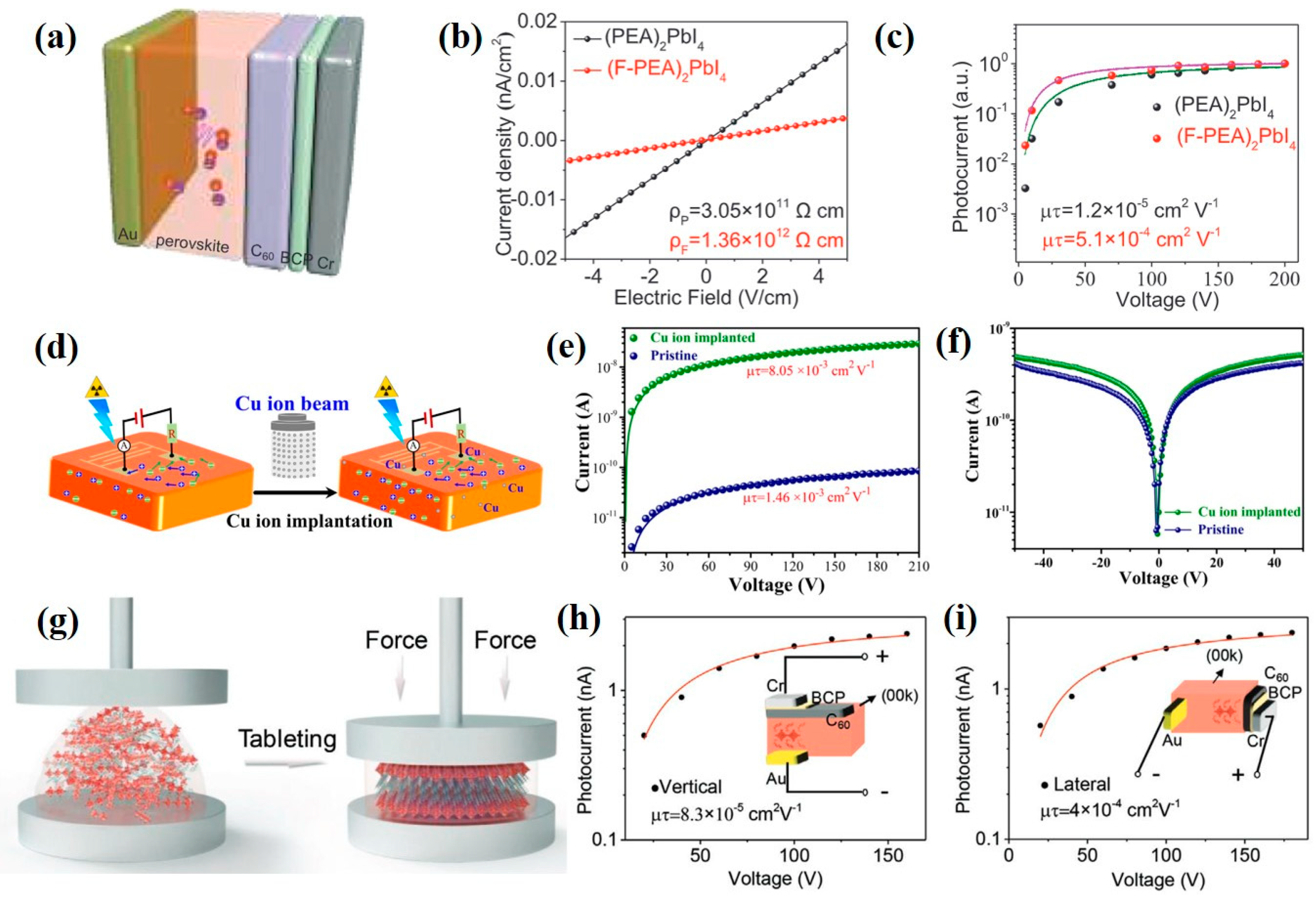
3.2.1. Two-Dimensional (2D) Perovskite Materials

The architecture and material properties of two-dimensional (2D) perovskite materials as well as their advantages were briefly introduced. Next, the recent research on the application of two-dimensional materials in X-ray sensing devices is summarized.

Single Crystal

Li et al. [53] used a 2D perovskite of (F-PEA)2PbI4 (F-PEA: fluorophenethyl) material as the active layer for the hard X-ray detector. Adding the fluorine atoms in the large-sized cation can strengthen the interaction between the fluorine atom and the benzene ring, which improves the stability, effectively suppresses the ion migration and reduces the dark current of the X-ray detector. Figure 2a is the structural architecture of the device. The device sensitivity under 120 kVp hard X-ray irradiation is 3402 μC·Gy−1air·cm−2 and its detection limit is 23 nGyair·s−1, as shown in Figure 2b and Figure 2c, respectively. Qian et al. [54] synthesized a 2D (PMA)2PbI4 single crystal and used the ion implantation to implant copper ions into the 2D perovskite (refer to Figure 2d). The quantum confinement effect of 2D layered perovskite can effectively suppress the dark current of the X-ray detector. The device sensitivity under the X-ray irradiation is 283 μC·Gyair−1·cm−2 and its detection limit is 2.13 μGyair·s−1, as shown in Figure 2e and Figure 2f, respectively.
Li et al. [55] fabricated a single crystal of (F-PEA)3BiI6 by pressing disordered two-dimensional perovskite powders into thick films with ordered single-crystal structures under high pressure. Figure 2g is the process of pressure tableting. Strong bonding energy between bismuth ions (Bi3+) and iodine ions (I) can effectively prevent ion migration and reduce the dark current of the X-ray detector. The device detection limit is 30 nGyair·s−1 and the electrical detection of different crystal orientations is compared in Figure 2h,i.

Film

Ledee et al. [51] deposited 2D layered perovskite of PEA2PbBr4 (PEA = C6H5C2H4NH3+) on a PET flexible substrate coated with interdigitated electrodes, and such a device structure works as a photoconductor, as shown in Figure 3a. The channel width and length of finger electrodes were designed as 7.56 mm and 20 µm, respectively, to assist the layered arrangement of 2D material and effectively collect the charge carriers. As shown in Figure 3b, when the dose rate increases, the sensitivity of X-ray detectors decreases. The sensitivity is calculated as the first derivative of photocurrent with respect to the dose rate and it is normalized by the total pixel area of 0.63 mm2. The device under X-ray irradiation of 150 kVp presented a sensitivity of 806 μC·Gyair−1·cm−2. Figure 3c shows the SNR as a function of dose rate. When the SNR of the X-ray detector is equal to 3, the corresponding detection limit reaches a low value of 42 nGyair·s−1.
Compared with the single crystal, the perovskite film has more defects, which results in increased dark current in the X-ray detector and thereby decreased device sensitivity. Due to the large-sized cation in the 2D perovskite, the ion migration can be inhibited to reduce the dark current of the device. However, the 2D perovskite has a poor light response to X-rays due to anisotropic charge transport. As a result, the device applying 2D perovskite delivers an inferior sensitivity compared to the 3D counterpart.

3.2.2. Quasi-2D Perovskite Materials

Ji et al. [56] produced a quasi-2D BA2EA2Pb3Br10 (BA: C4H9NH3; EA: C2H5NH3) perovskite as an X-ray absorber for the X-ray detector, and they utilized spontaneous ferroelectric polarization (Ps) to effectively separate the photoinduced carriers and facilitate their transport for better X-ray sensitivity, as shown in Figure 4a,b. Tsai et al. [57] used the 2D layered perovskite of (BA)2(MA)2Pb3I10 as the active layer material in an X-ray detector for converting X-rays into charges, and the device sensitivity reached 0.276 C·Gyair−1·cm−3, as shown in Figure 4c,d. In addition, Tsai et al. [58] also introduced n-butylamine iodide in the methylammonium lead iodide precursor to prepare a quasi-2D layered perovskite, as shown in Figure 4e. The corresponding device showed a stable performance for a detection time of more than 15 h, and the X-ray sensitivity of the device was 1214 µC·Gyair−1·cm−2, as shown in Figure 4f.

3.2.3. One-Dimensional (1D) Perovskite Materials

Zhang et al. [59] synthesized a 1D inorganic perovskite of CsPbI3 as an absorbing material for the conversion of X-ray photons into charge carriers, and the CsPbI3-based device had a high bulk resistivity of 7.4 × 10⁹ Ω·cm, a large mobility–lifetime product of 3.63 × 10⁻³ cm2·V−1 and X-ray sensitivity of 2.37 mC·Gy−1·cm−2.

3.2.4. Zero-Dimensional (0D) Perovskite Materials

Unlike the traditional 3D perovskite structures with corner-sharing BX6 octahedra, deficient perovskite has isolated BX6 octahedra, which results in a zero-dimensional (0D) perovskite structure. Xu et al. [60] used electrostatic-assisted spray coating to fabricate the all-inorganic 0D perovskite material of Cs2TeI6 with a large area for the X-ray detector. Figure 5a is the schematic illustration of the spraying process for preparing the Cs2TeI6 perovskite, and the device structure of the X-ray detector is composed of FTO/TiO2/Cs2TeI6/PTAA/Au (refer to the inset in Figure 5b). Under X-ray irradiation of 40 kVp and an electric field of 250 V·cm−1, the device sensitivity was 19.2 μC·Gyair−1cm−2. Figure 5b compares the X-ray attenuation efficiency of different active materials, including CdTe, a-Se and Cs2TeI6, with different thicknesses, indicating that the Cs2TeI6 perovskite exhibits a comparable X-ray attenuation efficiency to CdTe. Xu et al. [61] used the 0D single crystal of Cs4PbI6 perovskite to make an X-ray detection device, and its mobility–lifetime product (μτ) reached 9.7 × 10⁻⁴ cm2·V−1. Figure 5c shows the J–V curves of the fabricated device with different exposure dose rates and the resultant sensitivity of the device was 451.49 μC·Gyair−1·cm−2 at an operating bias of 30 V, as seen in Figure 5d.

3.3. A2B2X6 Double-Perovskite Materials

Inorganic Cs2AgBiBr6 double perovskite is the most popular material in the field of X-ray detection, and its advantages include elements with a large Z number, such as Ag and Bi, which have a high X-ray attenuation ability. When a large electric field is applied to the Cs2AgBiBr6-based X-ray detector, the Cs2AgBiBr6 double perovskite is durable. Moreover, the ion migration in the X-ray detector is inhibited to lower the dark current.
Steele et al. [62] used Cs2AgBiBr6 double perovskite for X-ray detection. The device architecture was composed of Au/Cs2AgBiBr6/Au stacking structure and its sensitivity to X-ray irradiation reached 105 μC·Gyair−1·cm−2, as shown in Figure 6a. In the research demonstrated by Pan et al. [63], they reduced the disordered arrangement of Ag+ and Bi3+ ions in the Cs2AgBiBr6 double perovskite through the control of thermal annealing and surface treatment, which increases the bulk resistivity of perovskite and reduces the dark current. It is indicated that this Cs2AgBiBr6 SC is a p-type semiconductor to facilitate hole transport.
Yuan et al. [64] proposed that phenethylamine bromide (PEABr) can strengthen the molecular arrangement in the Cs2AgBiBr6 perovskite and were able to in situ tune the order–disorder phase transition in the Cs2AgBiBr6 single crystals. Additionally, the improvement of ordering extent can effectively reduce the defect density of perovskite material and improve carrier mobility. These PEA-Cs2AgBiBr6 crystals were utilized in the application of X-ray detection. The working mechanism is shown in Figure 6b. The PEA-Cs2AgBiBr6-based device showed an enhanced X-ray response due to the improvement of carrier mobility, as shown in Figure 6c, and the sensitivity of the PEA-Cs2AgBiBr6-based X-ray detector was 288.8 µC·Gyair−1·cm−2.

3.4. A3B2X9 Lead-Free Perovskite Materials

Lead-free perovskite with a vacancy-ordered structure of A3B2X9 (A: Cs+, Rb+, NH4+; M: Bi3+, Sb3+; X: Br, I) is a potential candidate for X-ray detectors due to its eco-friendly composition and high attenuation coefficient to X-ray irradiation. This perovskite has an equivalent composition of AB2/3X3 that indicates that one in three octahedral B3+-sites is occupied by a vacancy for maintaining charge neutrality. These materials exhibit a layered structure as 2D layered perovskite derivatives. This perovskite contains heavy elements with a large Z number to deliver a high attenuation capability to X-ray irradiation based on the relationship α ∝ Z4/Eph3. The application of vacancy-ordered perovskite for X-ray detectors is introduced in this section.
Zhuang et al. [65] used a 2D layered perovskite single crystal of (NH4)3Bi2I9 for the X-ray detector. Due to its inherent 2D layered structure, ion migration in the (NH4)3Bi2I9 perovskite can be suppressed. The as-fabricated device presented a low detection limit of 55 nGyair·s−1 and exhibited a good X-ray attenuation performance due to the presence of the heavy element Bi. Dong et al. [66] applied the MA3Bi2I9 perovskite for the direct-conversion X-ray detector. They used the blade-coating method to deposit the perovskite film onto the ITO substrate and added the MACl additive to slow down the crystal growth rate to reduce pinholes in the blade-coated perovskite film. The X-ray sensitivity and the detection limit of the device were 100.16 μC·Gyair−1·cm−2 and 98.4 nGyair·s−1, respectively. Li et al. [67] synthesized a single-crystal, low-dimensional FA3Bi2I9 perovskite material as the X-ray absorber for an X-ray detector. Figure 7a shows the solution-processed method for the fabrication of the FA3Bi2I9 single crystal. The device had a high bulk resistivity of 7.8 × 10¹⁰ Ω·cm, and the X-ray detection limit and the sensitivity of the device were 200 nGyair·s−1 and 598.1 μC·Gyair−1·cm−2, respectively. Since the stability of the device is severely affected by the organic cations, Zhang et al. [68] synthesized an all-inorganic low-dimensional perovskite of Cs3Bi2I9 single crystal as the active layer for X-ray sensing. The Cs3Bi2I9 single crystal was formed by the solution method and then made into the X-ray sensing device, as shown in Figure 7b. The sensitivity and the detection limit of the device for X-ray sensing reached 1652.3 μC·Gyair−1·cm−2 and 130 nGyair·s−1, respectively.
According to the X-ray absorption mechanism, the active layer with heavy elements has high absorption of X-ray irradiation. Therefore, X-ray detectors using perovskite materials with heavy metal elements of bismuth have good sensitivity to X-ray irradiation. Compared with the organic–inorganic hybrid perovskites, the inorganic perovskites present superior resistance to moisture, so the inorganic Cs3Bi2I9 is a suitable material for X-ray sensing.

3.5. Large-Area Perovskite X-ray Detectors

To make the perovskite-based X-ray detector able to directly take 2D images, a large area of perovskite layers, greater than 100 cm2, is favorable for the integration on the commercial thin-film transistor array; therefore, a scalable deposition process for the perovskite active layer in the X-ray detector is necessary. In this section, we summarize the large-area deposition process of perovskite active layers for the manufacture of perovskite-based X-ray detectors and their performance under X-ray irradiation.
Many large-area deposition processes of perovskite active layers, such as inkjet printing, doctor blade coating, spray coating, etc., have been demonstrated. Mescher et al. [69] reported a direct-conversion X-ray detector, in which the perovskite film was inkjet-printed onto flexible substrates, as shown in Figure 8a. The as-fabricated device achieved a sensitivity of 59.9 µC·Gyair−1·cm−2 at a low external voltage (0.1 V) with 70 kVp X-ray irradiation. Liu et al. [70] demonstrated an X-ray detector via a low-cost ink-printed coating of CsPbBr3 quantum dots on a flexible substrate, as shown in Figure 8b. A sensitivity of 1450 µC·Gyair−1·cm−2 for the X-ray detector was obtained when the device was exposed to a low exposure dose rate of about 17.2 µGyair·s–1 under a bias voltage of 0.1 V. Li et al. [71] demonstrated a hybrid X-ray detector with Cs2AgBiBr6 and (C38H34P2)MnBr4 scintillators synthesized by the tablet-pressing method, as shown in Figure 8c. The addition of a (C38H34P2)MnBr4 scintillator in the X-ray detector could suppress the ion migration of Cs2AgBiBr6 perovskite to reduce the dark current and increase the carrier collection efficiency. The final device achieved a sensitivity of 114 µC·Gyair−1·cm−2 and a low detection limit of 200 nGyair·s–1 under a hard X-ray exposure of 120 kVp. Ciavatti et al. [72] introduced a bar-coated perovskite for the direct-conversion X-ray detector with a sensitivity of 494 µC·Gyair−1·cm−2 at 150 kVp X-ray irradiation under a low operating voltage of less than 4 V, as shown in Figure 8d. Guo et al. [73] provided a facile mobile-platform-assisted electrospray method for the preparation of perovskite films with a large area of 100 cm2 on flexible substrates. By adjusting the spraying parameters, it is possible to control the growth orientation of Cs2TeI6 perovskite. The Cs2TeI6-based X-ray detector, in which the perovskite shows a preferred crystalline orientation of (222) facet, achieves a resistivity of 1.9 × 10¹¹ Ω·cm and a sensitivity of 226.8 µC·Gyair−1·cm−2, as shown in Figure 8e. Kim et al. [22] used doctor blade coating to deposit a polycrystalline MAPbI3 thick film onto large-area thin-film transistor (TFT) substrates. This is the first work to directly deposit the MAPbI3 perovskite on a large-area TFT substrate. The device achieves a sensitivity of up to 1.1× 10⁴ μC·Gyair−1·cm−2 under irradiation from a 100 kVp X-ray source, which is higher than that of current X-ray detectors using amorphous selenium or thallium iodide. They adjusted the charge injection interface to reduce the dark current by overlaying two additional polymer/perovskite composites on the upper and lower interfaces of 830 μm thick MAPbI3. Yang et al. [74] proposed an aerosol–liquid–solid (ALS) process to prepare mixed halide perovskite thick films for direct-conversion X-ray detectors. The ALS process can produce high-quality perovskite films of different compositions on conductive glass substrates or TFT substrates and facilitate the vertical growth of perovskite grains without grain boundaries. Such a columnar perovskite grain significantly improves the carrier transport across the perovskite film. The X-ray detector with a CsPbI2Br thick film achieves a sensitivity of 1.48 × 10⁵ μC·Gyair−1·cm−2 and a low detection limit of 280 nGyair·s−1, as shown in Figure 8f. The authors further demonstrated the high-resolution imaging capability, good stability, and strong resistance to X-ray radiation damage for the CsPbI2Br-based X-ray detector.

4. Conclusions and Outlook

In recent years, many researchers have proposed to replace the commonly used a-Se with perovskite material as the absorber layer for X-ray detectors because of its excellent X-ray attenuation ratio, long carrier lifetime, high defect tolerance and long electron–hole drift length. Compared to an a-Se absorber layer, using emerging perovskite materials in an X-ray detector can provide better X-ray detection performance at a lower cost and with less environmental pollution. At the early stage in the development of perovskite-based X-ray detectors, single-crystal perovskite was used to replace a-Se in X-ray detectors and showed good performance in response to X-ray irradiation due to its high crystalline quality, smooth morphology, high bulk resistivity, low trap density and sufficient thickness to attenuate X-rays. Polycrystalline perovskite-based X-ray detectors show poorer performance than their single-crystalline counterparts because of the increased grain boundary. However, their fabrication methods have the potential for the mass production of thick perovskite films for large-area X-ray detectors. Organic–inorganic hybrid perovskite materials, such as MAPbI3 and MAPbBr3, are commonly used as absorbers for X-ray detectors, and their application in X-ray detectors shows good performance under X-ray irradiation. However, their environmental stability is a major challenge due to the rapid degradation of perovskite upon exposure to humidity, heat, light and oxygen. All inorganic perovskite materials, such as CsPbBr3, show better environmental stability than organic–inorganic perovskite, and the X-ray detectors with inorganic perovskite still have high X-ray sensitivity. The introduction of large-sized cations in the 3D perovskite separates the 3D perovskite into the 2D layered perovskite. The anisotropic carrier transport in the 2D layered perovskite can inhibit ion migration to reduce the dark current of the device but decrease the device’s performance in response to X-ray irradiation. As a result, the sensitivity of X-ray detectors using 2D perovskite is generally lower than that of their 3D perovskite counterparts. Quasi-2D perovskite material (n > 1) such as BA2EA2Pb3Br10 has a better response to X-rays than the pure 2D materials (n = 1) and still has good stability. After a long period of measurement, the X-ray detectors based on quasi-2D perovskite still maintain a very stable performance. The application of a 1D inorganic perovskite nanorod, such as CsPbI3, in the X-ray detector shows a high X-ray sensitivity owing to its high resistivity and large carrier mobility–lifetime product. The 0D all-inorganic perovskite material of Cs2TeI6 is demonstrated as a potential candidate for the X-ray detector by virtue of its high X-ray sensitivity and environmental stability. Double-perovskite materials, such as Cs2AgBiBr6, contain the large Z-numbered elements of Ag and Bi, which have a better ability to attenuate X-ray irradiation. Its stable crystal structure can effectively inhibit ion migration in the device under a bias voltage; therefore, the corresponding device has a low dark current. Lead-free perovskite materials with a composition formula of A3B2X9 (e.g., MA3Bi2I9 and Cs3Bi2I9), in which the Pb atoms are replaced with larger Z-numbered Bi atoms, show the advantages of high attenuation of X-rays and eco-friendly properties. These properties make such materials promising as active layers in X-ray sensing devices. Furthermore, all inorganic lead-free perovskite materials exhibit high resistance to moisture, so they are suitable candidates for X-ray detectors. The key device parameters of perovskite-based X-ray detectors are summarized in Table 1.
To meet the commercial requirements for flat panel X-ray detectors, direct deposition of a perovskite layer with an area larger than 100 cm2 on the thin-film transistor array is necessary. Large-area fabrication methods for preparing the thick perovskite film, such as inkjet printing, doctor blade coating, spray coating and the ALS process, are utilized to fabricate large-area perovskite-based X-ray detectors. The large-area fabrication methods with a low-temperature process can further deposit a perovskite thick film onto the flexible substrates or TFT modules. The improvement of perovskite film quality, film uniformity and composition uniformity are the major challenges for large-area perovskite film. The as-prepared perovskite thick film by these processes is a polycrystalline film that has abundant grain boundaries and defects to trap the photogenerated carriers and further reduce the X-ray detector performance. By optimizing the experimental parameters and precisely controlling the environment during the deposition of perovskite film, a large-area perovskite thick film with large grain size, uniform film morphology and composition and fewer defects can be obtained. In conclusion, it is worth devoting more efforts toward developing facile, low-cost and eco-friendly fabrication methods for the preparation of large-area, durable, uniform, highly sensitive, low-detection-limit and low-toxicity perovskite films for X-ray detection.

Author Contributions

Conceptualization, C.-F.L.; Writing—original draft, C.-F.L., K.-W.H., Y.-T.C. and S.-L.H.; Writing—review & editing, M.-H.L. and P.C.; Supervision, P.C. All authors have read and agreed to the published version of the manuscript.

Funding

The authors are grateful for the research grant from the Ministry of Science and Technology of Taiwan (MOST 111-2113-M-006-009 and MOST 111-2221-E-006-061-MY2). This work was financially supported by the Hierarchical Green-Energy Materials (Hi-GEM) Research Center from the Featured Areas Research Center Program within the framework of the Higher Education Sprout Project by the Ministry of Education (MOE) in Taiwan. This research was supported in part by the Higher Education Sprout Project of the Ministry of Education to the Headquarters of University Advancement at National Cheng Kung University (NCKU).

Data Availability Statement

Not applicable.

Conflicts of Interest

The authors declare no conflict of interest.

References

  1. Hoheisel, M. Review of medical imaging with emphasis on X-ray detectors. Nucl. Instrum. Methods Phys. Res. Sect. A Accel. Spectrom. Detect. Assoc. Equip. 2006, 563, 215–224. [Google Scholar] [CrossRef]
  2. Zhou, Y.; Chen, J.; Bakr, O.M.; Mohammed, O.F. Metal Halide Perovskites for X-ray Imaging Scintillators and Detectors. ACS Energy Lett. 2021, 6, 739–768. [Google Scholar] [CrossRef]
  3. Nikl, M.; Yoshikawa, A. Recent R&D Trends in Inorganic Single-Crystal Scintillator Materials for Radiation Detection. Adv. Opt. Mater. 2015, 3, 463–481. [Google Scholar]
  4. Weber, M.J. Inorganic scintillators: Today and tomorrow. J. Lumin. 2002, 100, 35–45. [Google Scholar] [CrossRef]
  5. Maddalena, F.; Xie, A.; Arramel; Witkowski, M.E.; Makowski, M.; Mahler, B.; Drozdowski, W.; Mariyappan, T.; Springham, S.V.; Coquet, P.; et al. Effect of commensurate lithium doping on the scintillation of two-dimensional perovskite crystals. J. Mater. Chem. C 2021, 9, 2504–2512. [Google Scholar] [CrossRef]
  6. Chen, Q.; Wu, J.; Ou, X.; Huang, B.; Almutlaq, J.; Zhumekenov, A.A.; Guan, X.; Han, S.; Liang, L.; Yi, Z.; et al. All-inorganic perovskite nanocrystal scintillators. Nature 2018, 561, 88–93. [Google Scholar] [CrossRef]
  7. Almeida, G.; Infante, I.; Manna, L. Resurfacing halide perovskite nanocrystals. Science 2019, 364, 833–834. [Google Scholar] [CrossRef]
  8. Quan, L.N.; García de Arquer, F.P.; Sabatini, R.P.; Sargent, E.H. Perovskites for light emission. Adv. Mater. 2018, 30, 1801996. [Google Scholar] [CrossRef]
  9. Voloshinovskii, A.S.; Mikhailik, V.B.; Myagkota, S.V.; Pidzyrailo, M.S.; Pashuk, I.P. Exciton luminescence of ionic semiconductors CsPbX3 (X = Cl, Br, I). Ukr. J. Phys. 1993, 38, 1012–1015. [Google Scholar]
  10. Belsky, A.; Chevallier, P.; Dhez, P.; Martin, P.; Pédrini, C.; Vasil’Ev, A. X-ray excitation of luminescence of scintillator materials in the 7–22 keV region. Nucl. Instrum. Methods Phys. Res. Sect. A Accel. Spectrom. Detect. Assoc. Equip. 1995, 361, 384–387. [Google Scholar] [CrossRef]
  11. Shibuya, K.; Koshimizu, M.; Takeoka, Y.; Asai, K. Scintillation properties of (C6H13NH3)2PbI4: Exciton luminescence of an organic/inorganic multiple quantum well structure compound induced by 2.0 MeV protons. Nucl. Instrum. Methods Phys. Res. Sect. B Beam Interact. Mater. At. 2002, 194, 207–212. [Google Scholar] [CrossRef]
  12. Huang, H.; Abbaszadeh, S. Recent Developments of Amorphous Selenium-Based X-ray Detectors: A Review. IEEE Sens. J. 2019, 20, 1694–1704. [Google Scholar] [CrossRef]
  13. Schieber, M.; Zuck, A.; Gilboa, H.; Zentai, G. Reviewing Polycrystalline Mercuric Iodide X-ray Detectors. IEEE Trans. Nucl. Sci. 2006, 53, 2385–2391. [Google Scholar] [CrossRef]
  14. Yun, M.-S.; Cho, S.-H.; Lee, R.; Jang, G.-W.; Kim, Y.-S.; Shin, W.-J.; Nam, S.-H. Investigation of PbI2 Film Fabricated by a New Sedimentation Method as an X-ray Conversion Material. Jpn. J. Appl. Phys. 2010, 49, 041801. [Google Scholar] [CrossRef]
  15. Kabir, M. Effects of charge carrier trapping on polycrystalline PbO X-ray imaging detectors. J. Appl. Phys. 2008, 104, 074506. [Google Scholar] [CrossRef]
  16. Szeles, C. CdZnTe and CdTe materials for X-ray and gamma ray radiation detector applications. Phys. Status Solidi B 2004, 241, 783–790. [Google Scholar] [CrossRef]
  17. Wei, H.; Huang, J. Halide lead perovskites for ionizing radiation detection. Nat. Commun. 2019, 10, 1–12. [Google Scholar] [CrossRef] [Green Version]
  18. Xu, X.; Qian, W.; Xiao, S.; Wang, J.; Zheng, S.; Yang, S. Halide perovskites: A dark horse for direct X-ray imaging. EcoMat 2020, 2, e12064. [Google Scholar] [CrossRef]
  19. Zhang, H.; Ji, X.; Yao, H.; Fan, Q.; Yu, B.; Li, J. Review on efficiency improvement effort of perovskite solar cell. Sol. Energy 2022, 233, 421–434. [Google Scholar] [CrossRef]
  20. SSchmidt-Mende, L.; Dyakonov, V.; Olthof, S.; Ünlü, F.; Lê, K.M.T.; Mathur, S.; Karabanov, A.D.; Lupascu, D.C.; Herz, L.M.; Hinderhofer, A.; et al. Roadmap on organic–inorganic hybrid perovskite semiconductors and devices. APL Mater. 2021, 9, 109202. [Google Scholar] [CrossRef]
  21. Stoumpos, C.C.; Malliakas, C.D.; Peters, J.A.; Liu, Z.; Sebastian, M.; Im, J.; Chasapis, T.C.; Wibowo, A.C.; Chung, D.Y.; Freeman, A.J.; et al. Crystal Growth of the Perovskite Semiconductor CsPbBr3: A New Material for High-Energy Radiation Detection. Cryst. Growth Des. 2013, 13, 2722–2727. [Google Scholar] [CrossRef]
  22. Kim, Y.C.; Kim, K.H.; Son, D.-Y.; Jeong, D.-N.; Seo, J.-Y.; Choi, Y.S.; Han, I.T.; Lee, S.Y.; Park, N.-G. Printable organometallic perovskite enables large-area, low-dose X-ray imaging. Nature 2017, 550, 87–91. [Google Scholar] [CrossRef]
  23. Pan, W.; Yang, B.; Niu, G.; Xue, K.H.; Du, X.; Yin, L.; Zhang, M.; Wu, H.; Miao, X.S.; Tang, J. Hot-Pressed CsPbBr3 Quasi-Monocrystalline Film for Sensitive Direct X-ray Detection. Adv. Mater. 2019, 31, 1904405. [Google Scholar] [CrossRef]
  24. Glushkova, A.; Andričević, P.; Smajda, R.; Náfrádi, B.; Kollár, M.; Djokić, V.; Arakcheeva, A.; Forró, L.; Pugin, R.; Horváth, E. Ultrasensitive 3D Aerosol-Jet-Printed Perovskite X-ray Photodetector. ACS Nano 2021, 15, 4077–4084. [Google Scholar] [CrossRef]
  25. Shockley, W. Problems related top-n junctions in silicon. Czechoslov. J. Phys. 1961, 11, 81–121. [Google Scholar] [CrossRef]
  26. Kakavelakis, G.; Gedda, M.; Panagiotopoulos, A.; Kymakis, E.; Anthopoulos, T.D.; Petridis, K. Metal Halide Perovskites for High-Energy Radiation Detection. Adv. Sci. 2020, 7, 2002098. [Google Scholar] [CrossRef]
  27. Uxa, Š.; Grill, R.; Belas, E. Evaluation of the mobility-lifetime product in CdTe and CdZnTe detectors by the transient-current technique. J. Appl. Phys. 2013, 114, 094511. [Google Scholar] [CrossRef]
  28. Basiricò, L.; Ciavatti, A.; Fraboni, B. Solution-Grown Organic and Perovskite X-ray Detectors: A New Paradigm for the Direct Detection of Ionizing Radiation. Adv. Mater. Technol. 2020, 6, 2000475. [Google Scholar] [CrossRef]
  29. Yang, T.; Li, F.; Zheng, R. Recent advances in radiation detection technologies enabled by metal-halide perovskites. Mater. Adv. 2021, 2, 6744–6767. [Google Scholar] [CrossRef]
  30. Thompson, M.; Ellison, S.L.R.; Wood, R. Harmonized guidelines for single-laboratory validation of methods of analysis (IUPAC Technical Report). Pure Appl. Chem. 2002, 74, 835–855. [Google Scholar] [CrossRef]
  31. Song, Y.; Li, L.; Bi, W.; Hao, M.; Kang, Y.; Wang, A.; Wang, Z.; Li, H.; Li, X.; Fang, Y.; et al. Atomistic surface passivation of CH3NH3PbI3 perovskite single crystals for highly sensitive coplanar-structure x-ray detectors. Research 2020, 2020, 5958243. [Google Scholar] [CrossRef]
  32. Wang, W.; Meng, H.; Qi, H.; Xu, H.; Du, W.; Yang, Y.; Yi, Y.; Jing, S.; Xu, S.; Hong, F. Electronic-Grade High-Quality Perovskite Single Crystals by a Steady Self-Supply Solution Growth for High-Performance X-ray Detectors. Adv. Mater. 2020, 32, 2001540. [Google Scholar] [CrossRef] [PubMed]
  33. Huang, Y.; Qiao, L.; Jiang, Y.; He, T.; Long, R.; Yang, F.; Wang, L.; Lei, X.; Yuan, M.; Chen, J. A-site cation engineering for highly efficient MAPbI3 single-crystal x-ray detector. Angew. Chem. Int. Ed. 2019, 58, 17834–17842. [Google Scholar] [CrossRef] [PubMed]
  34. Ye, F.; Lin, H.; Wu, H.; Zhu, L.; Huang, Z.; Ouyang, D.; Niu, G.; Choy, W.C. High-quality cuboid CH3NH3PbI3 single crystals for high performance X-ray and photon detectors. Adv. Funct. Mater. 2019, 29, 1806984. [Google Scholar] [CrossRef]
  35. Geng, X.; Zhang, H.; Ren, J.; He, P.; Zhang, P.; Feng, Q.; Pan, K.; Dun, G.; Wang, F.; Zheng, X.; et al. High-performance single crystal CH3NH3PbI3 perovskite x-ray detector. Appl. Phys. Lett. 2021, 118, 063506. [Google Scholar] [CrossRef]
  36. Shrestha, S.; Fischer, R.; Matt, G.J.; Feldner, P.; Michel, T.; Osvet, A.; Levchuk, I.; Merle, B.; Golkar, S.; Chen, H.; et al. High-performance direct conversion X-ray detectors based on sintered hybrid lead triiodide perovskite wafers. Nat. Photonics 2017, 11, 436–440. [Google Scholar] [CrossRef]
  37. Geng, X.; Feng, Q.; Zhao, R.; Hirtz, T.; Dun, G.; Yan, Z.; Ren, J.; Zhang, H.; Liang, R.; Tian, H.; et al. High-Quality Single Crystal Perovskite for Highly Sensitive X-ray Detector. IEEE Electron. Device Lett. 2019, 41, 256–259. [Google Scholar] [CrossRef]
  38. Xu, Q.; Shao, W.; Li, Y.; Zhang, X.; Ouyang, X.; Liu, J.; Liu, B.; Wu, Z.-Y.; Ouyang, X.; Tang, X.; et al. High-Performance Surface Barrier X-ray Detector Based on Methylammonium Lead Tribromide Single Crystals. ACS Appl. Mater. Interfaces 2019, 11, 9679–9684. [Google Scholar] [CrossRef]
  39. Pan, Y.; Wang, X.; Zhao, J.; Xu, Y.; Li, Y.; Li, Q.; Zhang, X.; Zhao, Z.; Zhu, Z.; Jing, C. Photodiodes based on a MAPbBr3/Bi3+-doped MAPbCl3 single crystals heterojunction for the X-ray detection. CrystEngComm 2021, 23, 4954–4962. [Google Scholar] [CrossRef]
  40. Fan, Z.; Liu, J.; Zuo, W.; Liu, G.; He, X.; Luo, K.; Ye, Q.; Liao, C. Mixed-Cation MAxCs1−xPbBr3 Perovskite Single Crystals with Composition Management for High-Sensitivity X-ray Detection. Phys. Status Solidi (RRL)–Rapid Res. Lett. 2020, 14, 2000226. [Google Scholar] [CrossRef]
  41. Liu, Y.; Zhang, Y.; Zhu, X.; Feng, J.; Spanopoulos, I.; Ke, W.; He, Y.; Ren, X.; Yang, Z.; Xiao, F. Triple-Cation and Mixed-Halide Perovskite Single Crystal for High-Performance X-ray Imaging. Adv. Mater. 2021, 33, 2006010. [Google Scholar] [CrossRef]
  42. Basiricò, L.; Senanayak, S.P.; Ciavatti, A.; Abdi-Jalebi, M.; Fraboni, B.; Sirringhaus, H. Detection of X-rays by solution-processed cesium-containing mixed triple cation perovskite thin films. Adv. Funct. Mater. 2019, 29, 1902346. [Google Scholar] [CrossRef]
  43. Possanzini, L.; Basiricò, L.; Ciavatti, A.; Tessarolo, M.; Fraboni, B. Fully Textile X-ray Detectors Based on Fabric-Embedded Perovskite Crystals. Adv. Mater. Interfaces 2022, 9, 2101417. [Google Scholar] [CrossRef]
  44. Fan, Z.; Liu, J.; Zuo, W.; Liu, G.; He, X.; Luo, K.; Ye, Q.; Liao, C. Solution-Processed MAPbBr3 and CsPbBr3 Single-Crystal Detectors with Improved X-ray Sensitivity via Interfacial Engineering. Phys. Status Solidi A 2020, 217, 2000104. [Google Scholar] [CrossRef]
  45. Zhang, H.; Wang, F.; Lu, Y.; Sun, Q.; Xu, Y.; Zhang, B.-B.; Jie, W.; Kanatzidis, M.G. High-sensitivity X-ray detectors based on solution-grown caesium lead bromide single crystals. J. Mater. Chem. C 2020, 8, 1248–1256. [Google Scholar] [CrossRef]
  46. Peng, J.; Xia, C.Q.; Xu, Y.; Li, R.; Cui, L.; Clegg, J.K.; Herz, L.M.; Johnston, M.B.; Lin, Q. Crystallization of CsPbBr3 single crystals in water for X-ray detection. Nat. Commun. 2021, 12, 1531. [Google Scholar] [CrossRef] [PubMed]
  47. Heo, J.H.; Shin, D.H.; Park, J.K.; Kim, D.H.; Lee, S.J.; Im, S.H. High-Performance Next-Generation Perovskite Nanocrystal Scintillator for Nondestructive X-ray Imaging. Adv. Mater. 2018, 30, e1801743. [Google Scholar] [CrossRef] [PubMed]
  48. Gou, Z.; Huanglong, S.; Ke, W.; Sun, H.; Tian, H.; Gao, X.; Zhu, X.; Yang, D.; Wangyang, P. Self-Powered X-ray Detector Based on All-Inorganic Perovskite Thick Film with High Sensitivity under Low Dose Rate. Phys. Status Solidi (RRL)–Rapid Res. Lett. 2019, 13, 1900094. [Google Scholar] [CrossRef]
  49. Matt, G.J.; Levchuk, I.; Knüttel, J.; Dallmann, J.; Osvet, A.; Sytnyk, M.; Tang, X.; Elia, J.; Hock, R.; Heiss, W.; et al. Sensitive Direct Converting X-ray Detectors Utilizing Crystalline CsPbBr3 Perovskite Films Fabricated via Scalable Melt Processing. Adv. Mater. Interfaces 2020, 7, 1901575. [Google Scholar] [CrossRef] [Green Version]
  50. Lai, P.-T.; Lin, H.-C.; Chuang, Y.-T.; Chen, C.-Y.; Cheng, W.-K.; Tan, G.-H.; Hsu, B.-W.; Yang, L.; Lou, S.-C.; Chien, L.-J.; et al. All-Vacuum-Deposited Perovskite X-ray Detector with a Record-High Self-Powered Sensitivity of 1.2 C Gy–1 cm–3. ACS Appl. Mater. Interfaces 2022, 14, 19795–19805. [Google Scholar] [CrossRef] [PubMed]
  51. Lédée, F.; Ciavatti, A.; Verdi, M.; Basiricò, L.; Fraboni, B. Ultra-Stable and Robust Response to X-rays in 2D Layered Perovskite Micro-Crystalline Films Directly Deposited on Flexible Substrate. Adv. Opt. Mater. 2022, 10, 2101145. [Google Scholar] [CrossRef]
  52. Shi, E.; Gao, Y.; Finkenauer, B.P.; Akriti, A.; Coffey, A.H.; Dou, L. Two-dimensional halide perovskite nanomaterials and heterostructures. Chem. Soc. Rev. 2018, 47, 6046–6072. [Google Scholar] [CrossRef]
  53. Li, H.; Song, J.; Pan, W.; Xu, D.; Zhu, W.; Wei, H.; Yang, B. Sensitive and STable 2D Perovskite Single-Crystal X-ray Detectors Enabled by a Supramolecular Anchor. Adv. Mater. 2020, 32, 2003790. [Google Scholar] [CrossRef] [PubMed]
  54. Qian, C.X.; Wang, M.Z.; Lu, S.S.; Feng, H.J. Fabrication of 2D perovskite (PMA) 2PbI4 crystal and Cu ion implantation improved X-ray detector. Appl. Phys. Lett. 2022, 120, 011901. [Google Scholar] [CrossRef]
  55. Li, M.; Li, H.; Li, W.; Li, B.; Lu, T.; Feng, X.; Guo, C.; Zhang, H.; Wei, H.; Yang, B. Oriented 2D Perovskite Wafers for Anisotropic X-ray Detection through a Fast Tableting Strategy. Adv. Mater. 2022, 34, 2108020. [Google Scholar] [CrossRef] [PubMed]
  56. Ji, C.; Wang, S.; Wang, Y.; Chen, H.; Li, L.; Sun, Z.; Sui, Y.; Wang, S.; Luo, J. 2D Hybrid Perovskite Ferroelectric Enables Highly Sensitive X-ray Detection with Low Driving Voltage. Adv. Funct. Mater. 2019, 30, 1905529. [Google Scholar] [CrossRef]
  57. Tsai, H.; Liu, F.; Shrestha, S.; Fernando, K.; Tretiak, S.; Scott, B.; Vo, D.T.; Strzalka, J.; Nie, W. A sensitive and robust thin-film X-ray detector using 2D layered perovskite diodes. Sci. Adv. 2020, 6, eaay0815. [Google Scholar] [CrossRef] [Green Version]
  58. Tsai, H.; Shrestha, S.; Pan, L.; Huang, H.-H.; Strzalka, J.; Williams, D.; Wang, L.; Cao, L.R.; Nie, W. Quasi-2D Perovskite Crystalline Layers for Printable Direct Conversion X-ray Imaging. Adv. Mater. 2022, 34, 2106498. [Google Scholar] [CrossRef]
  59. Zhang, B.-B.; Liu, X.; Xiao, B.; Ben Hafsia, A.; Gao, K.; Xu, Y.; Zhou, J.; Chen, Y. High-Performance X-ray Detection Based on One-Dimensional Inorganic Halide Perovskite CsPbI3. J. Phys. Chem. Lett. 2019, 11, 432–437. [Google Scholar] [CrossRef] [PubMed]
  60. Xu, Y.; Jiao, B.; Song, T.B.; Stoumpos, C.C.; He, Y.; Hadar, I.; Lin, W.; Kanatzidis, M.G. Zero-dimensional Cs2TeI6 perovskite: Solution-processed thick films with high X-ray sensitivity. ACS Photonics 2018, 6, 196–203. [Google Scholar] [CrossRef]
  61. Xu, Q.; Li, C.; Nie, J.; Guo, Y.; Wang, X.; Zhang, B.; Ouyang, X. Highly Sensitive and Stable X-ray Detector Based on a 0D Structural Cs4PbI6 Single Crystal. J. Phys. Chem. Lett. 2020, 12, 287–293. [Google Scholar] [CrossRef]
  62. Steele, J.A.; Pan, W.; Martin, C.; Keshavarz, M.; Debroye, E.; Yuan, H.; Banerjee, S.; Fron, E.; Jonckheere, D.; Kim, C.W.; et al. Photophysical Pathways in Highly Sensitive Cs2AgBiBr6 Double-Perovskite Single-Crystal X-ray Detectors. Adv. Mater. 2018, 30, 1804450. [Google Scholar] [CrossRef]
  63. Pan, W.; Wu, H.; Luo, J.; Deng, Z.; Ge, C.; Chen, C.; Jiang, X.; Yin, W.-J.; Niu, G.; Zhu, L.; et al. Cs2AgBiBr6 single-crystal X-ray detectors with a low detection limit. Nat. Photonics 2017, 11, 726–732. [Google Scholar] [CrossRef]
  64. Yuan, W.; Niu, G.; Xian, Y.; Wu, H.; Wang, H.; Yin, H.; Liu, P.; Li, W.; Fan, J. In Situ regulating the order–disorder phase transition in Cs2AgBiBr6 single crystal toward the application in an X-ray detector. Adv. Funct. Mater. 2019, 29, 1900234. [Google Scholar] [CrossRef]
  65. Zhuang, R.; Wang, X.; Ma, W.; Wu, Y.; Chen, X.; Tang, L.; Zhu, H.; Liu, J.; Wu, L.; Zhou, W.; et al. Highly sensitive X-ray detector made of layered perovskite-like (NH4)3Bi2I9 single crystal with anisotropic response. Nat. Photonics 2019, 13, 602–608. [Google Scholar] [CrossRef]
  66. Dong, S.; Xin, D.; Zhang, M.; Tie, S.; Cai, B.; Ma, Q.; Zheng, X. Green solvent blade-coated MA3Bi2I9 for direct-conversion X-ray detectors. J. Mater. Chem. C 2022, 10, 6236–6242. [Google Scholar] [CrossRef]
  67. Li, W.; Xin, D.; Tie, S.; Ren, J.; Dong, S.; Lei, L.; Zheng, X.; Zhao, Y.; Zhang, W. Zero-Dimensional Lead-Free FA3Bi2I9 Single Crystals for High-Performance X-ray Detection. J. Phys. Chem. Lett. 2021, 12, 1778–1785. [Google Scholar] [CrossRef]
  68. Zhang, Y.; Liu, Y.; Xu, Z.; Ye, H.; Yang, Z.; You, J.; Liu, M.; He, Y.; Kanatzidis, M.G.; Liu, S. Nucleation-controlled growth of superior lead-free perovskite Cs3Bi2I9 single-crystals for high-performance X-ray detection. Nat. Commun. 2020, 11, 1–11. [Google Scholar]
  69. Mescher, H.; Schackmar, F.; Eggers, H.; Abzieher, T.; Zuber, M.; Hamann, E.; Baumbach, T.; Richards, B.S.; Hernandez-Sosa, G.; Paetzold, U.W.; et al. Flexible Inkjet-Printed Triple Cation Perovskite X-ray Detectors. ACS Appl. Mater. Interfaces 2020, 12, 15774–15784. [Google Scholar] [CrossRef]
  70. Liu, J.; Shabbir, B.; Wang, C.; Wan, T.; Ou, Q.; Yu, P.; Tadich, A.; Jiao, X.; Chu, D.; Qi, D.; et al. Flexible, printable soft-X-ray detectors based on all-inorganic perovskite quantum dots. Adv. Mater. 2019, 31, 1901644. [Google Scholar] [CrossRef] [PubMed]
  71. Li, W.; Liu, L.; Tan, M.; He, Y.; Guo, C.; Zhang, H.; Wei, H.; Yang, B. Low-Cost and Large-Area Hybrid X-ray Detectors Combining Direct Perovskite Semiconductor and Indirect Scintillator. Adv. Funct. Mater. 2021, 31, 2107843. [Google Scholar] [CrossRef]
  72. Ciavatti, A.; Sorrentino, R.; Basiricò, L.; Passarella, B.; Caironi, M.; Petrozza, A.; Fraboni, B. High-Sensitivity Flexible X-ray Detectors based on Printed Perovskite Inks. Adv. Funct. Mater. 2021, 31, 2009072. [Google Scholar] [CrossRef]
  73. Guo, J.; Chen, S.; Xu, Y.; Li, F.; Jie, W.; Zhu, M. Oriented preparation of Large-Area uniform Cs2TeI6 perovskite film for high performance X-ray detector. J. Colloid Interface Sci. 2022, 624, 629–636. [Google Scholar] [CrossRef] [PubMed]
  74. Qian, W.; Xu, X.; Wang, J.; Xu, Y.; Chen, J.; Ge, Y.; Chen, J.; Xiao, S.; Yang, S. An aerosol-liquid-solid process for the general synthesis of halide perovskite thick films for direct-conversion X-ray detectors. Matter 2021, 4, 942–954. [Google Scholar] [CrossRef]
Figure 2. (a) Device structure, (b) dark current density and (c) photocurrent of self-powered X-ray detector based on 2D (F-PEA)2PbI4 perovskite [53]. (d) Schematic diagram of Cu ion implantation on the (PMA)2PbI4-based X-ray detector. (e) Sensitivity and (f) detection limit of (PMA)2PbI4-based X-ray detector after ion implantation [54]. (g) Schematic diagram of tableting process for the (F-PEA)3BiI6 SCs. Photocurrent of X-ray detector using (F-PEA)3BiI6 single crystal under (h) vertical and (i) horizontal electric fields [55].
Nanomaterials 13 02024 g002
Figure 3. (a) Photoconductor-type X-ray detectors by deposition of 2D PEA2PbBr4 micro-crystalline films on a flexible PET substrate. (b) Sensitivity per unit area (SA, black curve) and photocurrent (orange curve) as a function of dose rate. (c) SNR as a function of dose rate for the device under 150 kVp (blue curve) and 40 kVp (orange curve) accelerating voltages [51].
Nanomaterials 13 02024 g003
Figure 4. (a) Crystal structure of the quasi-2D BA2EA2Pb3Br10 perovskite. (b) X-ray-generated photocurrent of BA2EA2Pb3Br10 perovskite at various dose rates at a bias of 10 V [56]. (c) A p–i–n device architecture and (d) J–V curve of X-ray detector based on quasi-2D (BA)2(MA)2Pb3I10 perovskite [57]. (e) Fabrication process of thick film growth of quasi-2D perovskite and (f) J–V curve of corresponding X-ray detector [58].
Nanomaterials 13 02024 g004
Figure 5. (a) Schematic illustration of electrostatic-assisted spray coating process for deposition of large-area Cs2TeI6 perovskite. (b) Comparison of attenuation efficiency of CdTe, a-Se and Cs2TeI6 with different thicknesses for X-ray irradiation. Inset illustrates the device structure [60]. (c) J–V curves and (d) photocurrent as a function of dose rate of X-ray detector using Cs4PbI6 single crystal [61].
Nanomaterials 13 02024 g005
Figure 6. (a) Photo of X-ray detector with a device architecture of Au/Cs2AgBiBr6 perovskite/Au [62]. (b) I–V curves of X-ray detectors using pristine Cs2AgBiBr6 and PEA-Cs2AgBiBr6 single-crystal. (c) X-ray response of the Cs2AgBiBr6- and PEA-Cs2AgBiBr6-based devices [64].
Nanomaterials 13 02024 g006
Figure 7. (a) FA3Bi2I9 single crystal synthesized by the solution method through controlling the growth mechanism [67]. (b) Schematic diagram of preparation of the Cs3Bi2I9 single crystals by the nucleation-controlled solution method [68].
Nanomaterials 13 02024 g007
Figure 8. Application of large-area perovskite film for X-ray detectors. (a) Reliability of sensitivity for X-ray detectors fabricated on rigid and flexible substrates [69]. (b) Photo of large-area CsPbBr3 quantum dots deposited on TFT array [70]. (c) Illustration of working principle of X-ray detector using mixed Cs2AgBiBr6/(C36H34P2)MnBr4 scintillator [71]. (d) Cross-sectional SEM and X-ray photo-response of the device with bar coating of MAPbI3:PC60BM mixed absorber [72]. (e) Large-area lead-free Cs2TeI6 perovskite fabricated by electro-spraying on flexible substrates and the relationship between the photocurrent density of Cs2TeI6-based device and the exposure dose rate [73]. (f) Schematic illustration of the perovskite layer prepared by the ALS process [74].
Nanomaterials 13 02024 g008
Table 1. Summary of key parameters of perovskite-based X-ray detectors.
Crystal StructureMaterialsCrystal TypeGrowth MethodThickness
(mm)
E
(V·mm−1)

(cm2·V−1)
S
(μC·Gyair−1·cm−2)
LoD
(nGyair·s−1)
Ref.
ABX3
(Organic)
MAPbI3Single
crystals
ITCNA100NA700,0001.5[31]
MAPbI3Single
crystals
ITCNA101.6 × 10−3NANA[32]
MAPbI3Single
crystals
ITC1.2 ± 0.04NA5.3 × 10−33.67 × 10380.6[33]
DMAMAPbI3Single
crystals
ITC1.2 ± 0.04NA7.2 × 10−31.18 × 10416.9[33]
GAMAPbI3Single
crystals
ITC1.2 ± 0.04NA1.3 × 10−22.31 × 10416.9[33]
MAPbI3Single
crystals
Solution 1NA1.49 × 10−3968.9NA[34]
MAPbI3Single
crystals
Solution 2~33.32.57 × 10−31471.146,000[35]
MAPbI3Polycrystals (wafer)Sintering process0.2~12002 × 10−42527NA[36]
MAPbBr3Single
crystals
ITCNA0.834.1 × 10−2259.9NA[37]
MAPbBr3Single
crystals
Solution NA1.43 × 104NA35922,100[38]
MAPbBr3Single
crystals
Fully textile0.0517NA12.2 ± 0.63000 (for stacked)/8000 (for planar)[43]
Bi3+-doped
MAPbBr3
Single
crystals
Solution 1.6831.54.12 × 10−41.72 × 10³NA[39]
MA0.6Cs0.4PbBr3Single
crystals
Solution 2NA4.64 × 10220171200[40]
FA0.85MA0.1Cs0.05Pb
I2.55Br0.45
Single
crystals
Thermal evaporation1−60NA(3.5 ± 0.2) × 106NA[41]
Cs0.05FA0.79MA0.16Pb(I0.8 Br0.2)3FilmSpin coating4.5 × 10−4200NA3.7 ± 0.1NA[42]
ABX3
(Inorganic)
CsPbBr3Single
crystals
Solution NA45−NA255220,900[44]
CsPbBr3Single
crystals
Solution 120(2.5 ± 0.2) × 10−31256NA[45]
CsPbBr3Single
crystals
LTC1NANA4086NA[46]
CsPbBr3MicrocrystalsSolution 0.0180NA47053[48]
CsPbBr3MicrocrystalsVitreous enamel0.11.2 × 104NA1450NA[49]
CsPbBr3Quasi-monocrystalHot pressing0.244.21.32 × 10−255,684215[23]
CsPbI2BrFilmCo-evaporation0.001NANA1.2 × 10625.69[50]
2D(F-PEA)2PbI4 Single
crystals
Solution 21335.1 × 10−4340223[53]
(PMA)2PbI4Single
crystals
Cooling crystallization 0.9NA8.05 × 10−32832.13[54]
(F-PEA)3BiI6Single
crystals
Tablet pressing NA1008.3 × 10−5118.630[55]
PEA2PbBr4FilmSpin coating1.9 ± 0.8 × 10−35001.09 ± 0.07 × 10−580642[51]
Q-2DBA2EA2Pb3Br10Single
crystals
Cooling crystallizationNA20k7.6 × 10−36.8 × 1035500[56]
BA2EA2Pb3I10FilmHot casting 4.70 × 10⁻⁴NANA276,00010,000[57]
MAPbI3/n-butylamine iodideFilmSpin coating2–3 × 10⁻³NANA1214NA[58]
1DCsPbI3PolycrystalsSolutionNANA3.63 × 10−3237059.7[59]
0DCs2TeI6PolycrystalsE-spray deposition 0.52505.2 × 10−519.2NA[60]
Cs4PbI6Single crystalsSolution NANA9.7 × 10−4451.4990[61]
A2B2X6Cs2AgBiBr6Single
crystals
Solution2NANA10559.7[62]
Cs2AgBiBr6Single
crystals
Solution225NA10559.7[63]
Cs2AgBiBr6Single
crystals
Solution2.222.7NA288NA[64]
A3B2X9MA3Bi2I9FilmBlade coating50 × 10−3−3000 V cm−19.7 × 10−6100.1698.4[66]
FA3Bi2I9 Single
crystals
SSCE 0.9NANA598.10.2[67]
Cs3Bi2I9Single
crystals
Solution1.250NA1652.3130[68]
Large area processMAPbI3NanocrystalsBar coating10 × 10−3800NA230027,000[72]
MAPbI3PolycrystalsDoctor blade coating0.8310–2401.5 × 10−41.1× 104300[22]
CsPbBr3Monocrystal (quantum dot)Inkjet printing2 × 10−50.1 VNA1450<17,200[70]
CsPbI2BrPolycrystalsALS process0.041251.14148,000280[74]
Cs0.1(FA0.83MA0.17)0.9Pb(Br0.17I0.83)3 PolycrystalsInkjet printing3.7 × 10−3272.0 × 10−659.912,000[69]
Cs2TeI6PolycrystalsElectro-spraying 1.5 × 10−36670NA227115[73]
Cs2ABiBr6/
(C38H34P2)MnBr4
PolycrystalsTablet pressing1.71008.5 × 10−5114200[71]
ITC: inverse temperature crystallization, LTC: low-temperature crystallization, SSCE: secondary solution constant temperature evaporation, ALS: aerosol–liquid–solid.
Disclaimer/Publisher’s Note: The statements, opinions and data contained in all publications are solely those of the individual author(s) and contributor(s) and not of MDPI and/or the editor(s). MDPI and/or the editor(s) disclaim responsibility for any injury to people or property resulting from any ideas, methods, instructions or products referred to in the content.

