
A Chromate-Free and Convenient Route to Fabricate Thin and Compact Conversion Coating for Corrosion Protection on LZ91 Magnesium Alloy

 , , and
Abstract
:1. Introduction
2. Experimental Procedure
2.1. Materials and Preparation of Specimens
2.2. Conversion Coating Treatment
2.3. Coating Characterization
2.4. Corrosion Behavior of the Coating
3. Results and Discussion
3.1. The Properties of the Specimens
3.2. The Properties of the Conversion Coating
3.3. The Formation Mechanism for the Conversion Coating
4. Conclusions
Author Contributions
Funding
Institutional Review Board Statement
Informed Consent Statement
Data Availability Statement
Acknowledgments
Conflicts of Interest
References
- Haferkamp, H.; Boehm, R.; Holzkamp, U.; Jaschik, C.; Kaese, V.; Niemeyer, M. Alloy Development, Processing and Applications in Magnesium Lithium Alloys. Mater. Trans. 2001, 42, 1160–1166. [Google Scholar] [CrossRef] [Green Version]
- Sanschagrin, A.; Tremble, R.; Angers, R.; Dubé, D. Mechanical properties and microstructure of new magnesium–Lithium base alloys. Mater. Sci. Eng. A 2001, 220, 69–77. [Google Scholar] [CrossRef]
- Wu, R.; Qu, Z.; Zhang, M. Effects of the addition of Y in Mg–8Li– (1,3) Al alloy. Mater. Sci. Eng. A 2009, 516, 96–99. [Google Scholar] [CrossRef]
- Xu, T.; Yang, Y.; Peng, X.; Song, J.; Pan, F. Overview of advancement and development trend on magnesium alloy. J. Magnes. Alloy. 2019, 7, 536–544. [Google Scholar] [CrossRef]
- Braga, D.F.O.; Tavares, S.M.O.; da Silva, L.F.M.; Moreira, P.M.G.P.; de Castro, P.M.S.T. Advanced design for lightweight structures: Review and prospects. Prog. Aerosp. Sci. 2014, 69, 29–39. [Google Scholar] [CrossRef]
- Yang, H.; Guo, X.; Chen, X.; Birbilis, N. A homogenisation pre-treatment for adherent and corrosion resistant Ni electroplated coatings on Mg-alloy AZ91D. Corros. Sci. 2014, 79, 41–49. [Google Scholar] [CrossRef]
- Singh, C.; Tiwari, S.K.; Singh, R. Development of corrosion-resistant electroplating on AZ91 Mg alloy by employing air and water-stable eutectic based ionic liquid bath. Surf. Coat. Technol. 2021, 428, 127881. [Google Scholar] [CrossRef]
- Yin, T.T.; Wu, R.; Leng, Z.; Du, G.; Guo, X.; Zhang, M.; Zhang, J.H. The process of electroplating with Cu on the surface of Mg-Li alloy. Surf. Coat. Technol. 2013, 225, 119–125. [Google Scholar] [CrossRef]
- Ghavidel, N.; Allahkaram, S.R.; Nederi, R.; Barzegar, M.; Bakhshandeh, H. Corrosion and wear behavior of an electroless Ni-P/nano-SiC coating on AZ31 Mg alloy obtained through environmentally-friendly conversion coating. Surf. Coat. Technol. 2020, 382, 125156. [Google Scholar] [CrossRef]
- Zhang, H.; Wang, S.; Yao, G.; Hua, Z. Electroless Ni–P plating on Mg–10Li–1Zn alloy. J. Alloys Compd. 2009, 474, 306–310. [Google Scholar] [CrossRef]
- Yang, L.; Li, J.; Zheng, Y.; Jiang, W.; Zheng, M. Electroless Ni–P plating with molybdate pretreatment on Mg–8Li alloy. J. Alloys Compd. 2009, 467, 562–566. [Google Scholar] [CrossRef]
- Jin, J.; Liu, C.; Fu, S.; Guo, Y.; Shu, X. Electroless Ni-P plating on Mg-10Gd-4.8Y-0.6Zr magnesium alloy with a new pretreatment process. Surf. Coat. Technol. 2011, 206, 348–353. [Google Scholar] [CrossRef]
- Li, J.F.; Zheng, Z.Q.; Li, S.C.; Ren, W.D.; Zheng, Z. Preparation and galvanic anodizing of a Mg-Li alloy. Mater. Sci. Eng. A 2006, 433, 233–240. [Google Scholar] [CrossRef]
- Garcia-Vergara, S.J.; Skeldon, P.; Thompson, G.E.; Habazaki, H. A flow model of porous anodic film growth on aluminum. Electrochim. Acta 2006, 52, 681–687. [Google Scholar] [CrossRef]
- Wu, G.; Zeng, X.; Ding, W.; Guo, X.; Yao, S. Characterization of ceramic PVD thin films on AZ31 magnesium alloys. Appl. Surf. Sci. 2006, 252, 7422–7429. [Google Scholar] [CrossRef]
- Chen, X.B.; Chong, K.; Abbott, T.B.; Birbilis, N.; Easton, M.A. 15-Biocompatible strontium-phosphate and manganese-phosphate conversion coatings for magnesium and its alloys. In Surface Modification of Magnesium and Its Alloys for Biomedical Applications; Woodhead Publishing: Cambridge, UK, 2015; pp. 407–432. [Google Scholar]
- Doerre, M.; Hibbitts, L.; Patrick, G.; Akafuah, N.K. Advances in Automotive Conversion Coatings during Pretreatment of the Body Structure: A Review. Coatings 2018, 8, 405. [Google Scholar] [CrossRef] [Green Version]
- Jian, S.Y.; Chu, Y.R.; Lin, C.S. Permanganate conversion coating on AZ31 magnesium alloys with enhanced corrosion resistance. Corros. Sci. 2015, 93, 301–309. [Google Scholar] [CrossRef]
- Hung, S.M.; Lin, H.; Chen, H.W.; Chen, S.Y.; Lin, C.S. Corrosion resistance and electrical contact resistance of a thin permanganate conversion coating on dual-phase LZ91 Mg–Li alloy. J. Mater. Res. Technol. 2021, 11, 1953–1968. [Google Scholar] [CrossRef]
- Zucchi, F.; Frignani, A.; Grassi, V.; Trabanelli, G.; Monticelli, C. Stannate and permanganate conversion coatings on AZ31 magnesium alloy. Corros. Sci. 2007, 49, 4542–4552. [Google Scholar] [CrossRef]
- Zhang, H.; Yao, G.; Wang, S.; Liu, Y.; Luo, H. A chrome-free conversion coating for magnesium–lithium alloy by a phosphate–permanganate solution. Surf. Coat. Technol. 2008, 202, 1825–1830. [Google Scholar] [CrossRef]
- Lee, Y.L.; Chu, Y.R.; Li, W.C.; Lin, C.S. Effect of permanganate concentration on the formation and properties of phosphate/permanganate conversion coating on AZ31 magnesium alloy. Corros. Sci. 2013, 70, 74–81. [Google Scholar] [CrossRef]
- Song, Y.; Shan, D.; Chen, R.; Zhang, F.; Han, E.H. Formation Mechanism of Phosphate Conversion Film on Mg-8.8 Li Alloy. Corros. Sci. 2009, 51, 62–69. [Google Scholar] [CrossRef]
- Wu, Q.; Yu, B.; Zhou, P.; Zhang, T.; Wang, F. Fabrication of phosphate conversion coatings on rolled AZ31 magnesium alloy: Variation of corrosion resistance on different planes induced by the crystallographic texture. Mater. Chem. Phys. 2021, 273, 125121. [Google Scholar] [CrossRef]
- Liao, S.; Yu, B.; Zhang, B.; Zhou, P.; Zhang, T.; Wang, F. Chemically depleting the noble impurities from AZ91-T4 magnesium alloy: A new and efficient pretreatment method to improve the corrosion resistance of phosphate conversion coatings. Corros. Sci. 2021, 191, 109725. [Google Scholar] [CrossRef]
- Lin, C.S.; Lee, C.Y.; Li, W.C.; Chen, Y.S.; Fang, G.N. Formation of Phosphate/Permanganate Conversion Coating on AZ31 Magnesium Alloy. J. Electrochem. Soc. 2006, 153, 90–96. [Google Scholar] [CrossRef]
- Wang, G.; Zhang, M.; Wu, R. Molybdate and molybdate/permanganate conversion coatings on Mg–8.5 Li alloy. Appl. Surf. Sci. 2012, 258, 2648–2654. [Google Scholar] [CrossRef]
- Yang, L.; Zhang, M.; Li, J.; Yu, X.; Niu, Z. Stannate conversion coatings on Mg–8Li alloy. J. Alloys Compd. 2009, 471, 197–200. [Google Scholar] [CrossRef]
- Lee, Y.L.; Chu, Y.R.; Chen, F.J.; Lin, C.S. Mechanism of the formation of stannate and cerium conversion coatings on AZ91D magnesium alloys. Appl. Surf. Sci. 2013, 276, 578–585. [Google Scholar] [CrossRef]
- Guo, L.; Zhang, F.; Song, L.; Zeng, R.C.; Li, S.Q.; Han, E.H. Corrosion resistance of ceria/polymethyltrimethoxy silane modified magnesium hydroxide coating on AZ31 magnesium alloy. Surf. Coat. Technol. 2017, 328, 121–133. [Google Scholar] [CrossRef]
- Montemor, M.; Simoes, A.; Carmezim, M. Characterization of rare-earth conversion films formed on the AZ31 magnesium alloy and its relation with corrosion protection. Appl. Surf. Sci. 2007, 253, 6922–6931. [Google Scholar] [CrossRef]
- Rudd, A.L.; Breslin, C.B.; Mansfeld, F. The corrosion protection afforded by rare earth conversion coatings applied to magnesium. Corros. Sci. 2000, 42, 275–288. [Google Scholar] [CrossRef] [Green Version]
- Jian, S.Y.; Chang, K.L. Effect of cerium ion on the microstructure and properties of permanganate conversion coating on LZ91 magnesium alloy. Appl. Surf. Sci. 2020, 509, 144767. [Google Scholar] [CrossRef]
- Jian, S.Y.; Tzeng, Y.C.; Ger, M.D.; Chang, K.L.; Shi, G.N.; Huang, W.H.; Chen, C.Y.; Wu, C.C. The study of corrosion behavior of manganese-based conversion coating on LZ91 magnesium alloy: Effect of addition of pyrophosphate and cerium. Mater. Des. 2020, 192, 108707. [Google Scholar] [CrossRef]
- Jian, S.Y.; Yang, C.Y.; Chang, J.K. Robust corrosion resistance and self-healing characteristics of a novel Ce/Mn conversion coatings on EV31 magnesium alloys. Appl. Surf. Sci. 2020, 510, 145385. [Google Scholar] [CrossRef]
- Höche, D.; Nowak, A.; John-Schillings, T. Surface cleaning and pre-conditioning surface treatments to improve the corrosion resistance of magnesium (Mg) alloys. In Corrosion Prevention of Magnesium Alloy; Woodhead Publishing: Cambridge, UK, 2013; pp. 87–109. [Google Scholar]
- Yuan, J.; Li, P.; Yuan, R.; Mao, D.; Zhao, S.; Feng, T. Influence of pickling time on electroless Ni–P coating on magnesium alloy. Mater. Corros.-Werkst. Korros. 2020, 72, 642–651. [Google Scholar] [CrossRef]
- Elsentriecy, H.H.; Azumi, K.; Konno, H. Effect of surface pretreatment by acid pickling on the density of stannate conversion coatings formed on AZ91 D magnesium alloy. Surf. Coat. Technol. 2007, 202, 532–537. [Google Scholar] [CrossRef]
- Su, H.Y.; Li, W.J.; Lin, C.S. Effect of Acid Pickling Pretreatment on the Properties of Cerium Conversion Coating on AZ31 Magnesium Alloy. J. Electrochem. Soc. 2012, 159, 219–225. [Google Scholar] [CrossRef]
- Dong, X. Surface Treatments for Magnesium Alloys; Singapore Institute of Manufacturing Technology: Singapore, 2015. [Google Scholar]
- Song, D.; Jing, X.; Wang, J.; Lu, S.; Yang, P.; Wang, Y.; Zhang, M. Microwave-assisted synthesis of lanthanum conversion coating on Mg–Li alloy and its corrosion resistance. Corros. Sci. 2011, 53, 3651–3656. [Google Scholar] [CrossRef]
- Yang, H.Y.; Chen, X.B.; Guo, X.W.; Wu, G.H.; Ding, W.J.; Birbilis, N. Coating pretreatment for Mg alloy AZ91D. Appl. Surf. Sci. 2012, 258, 5472–5481. [Google Scholar] [CrossRef]
- Jiang, X.; Guo, R.; Jiang, S. Evaluation of self-healing ability of Ce–V conversion coating on AZ31 magnesium alloy. J. Magnes. Alloys 2016, 4, 230–241. [Google Scholar] [CrossRef] [Green Version]
- Yang, X.; Wang, G.; Dong, G.; Gong, F.; Zhang, M. Rare earth conversion coating on Mg–8.5 Li alloys. J. Alloys Compd. 2009, 487, 64–68. [Google Scholar] [CrossRef]
- ASTM B117-03; Practice for Operating Salt Spray (Fog) Apparatus, ASTM Volume 03.02: Corrosion of Metals; Wear and Erosion. ASTM: West Conshohocken, PA, USA, 2022. [CrossRef]
- ASTM D610-08; Practice for Evaluating Degree of Rusting on Painted Steel Surfaces, ASTM Volume 06.01: Paint—Tests for Chemical, Physical, and Optical Properties; Appearance. ASTM: West Conshohocken, PA, USA, 2022. [CrossRef]
- Lee, Y.L.; Chen, F.J.; Lin, C.S. Corrosion Resistance Studies of Cerium Conversion Coating with a Fluoride-Free Pretreatment on AZ91D Magnesium Alloy. J. Electrochem. Soc. 2013, 160, 28–35. [Google Scholar] [CrossRef]
- Chong, K.Z.; Shih, T.S. Conversion-coating treatment for magnesium alloys by a permanganate–phosphate solution. Mater. Chem. Phys. 2003, 80, 191–200. [Google Scholar] [CrossRef]
- Zhou, W.; Shan, D.; Han, E.H.; Ke, W. Structure and formation mechanism of phosphate conversion coating on die-cast AZ91D magnesium alloy. Corros. Sci. 2008, 50, 329–337. [Google Scholar] [CrossRef]
- Chen, X.B.; Zhou, X.; Abbott, T.B.; Easton, M.A.; Birbilis, N. Double-layered manganese phosphate conversion coating on magnesium alloy AZ91D: Insights into coating formation, growth and corrosion resistance. Surf. Coat. Technol. 2013, 217, 147–155. [Google Scholar] [CrossRef]
- Wang, H.; Li, Y.; Wang, F. Influence of cerium on passivity behavior of wrought AZ91 alloy. Electrochim. Acta 2008, 54, 706–713. [Google Scholar] [CrossRef]
- Sun, Y.H.; Wang, R.C.; Peng, C.Q.; Feng, Y.; Yang, M. Corrosion behavior and surface treatment of superlight Mg−Li alloys. Trans. Nonferrous Met. Soc. China 2017, 27, 1455–1475. [Google Scholar] [CrossRef]
- Ohara, M.; Okahara, H.; Takigawa, Y.; Higashi, K. Clarification of the Necessary Value of Surface Roughness for Developing Luster on an AZ31 Magnesium Alloy Surface with or without Acid Aqueous Solution Treatment. Mater. Trans. 2008, 49, 909–912. [Google Scholar] [CrossRef] [Green Version]
- Polissar, M.J. The Kinetics of the Reaction between Permanganate and Manganous Ions. J. Phys. Chem. 1935, 39, 1057–1066. [Google Scholar] [CrossRef]


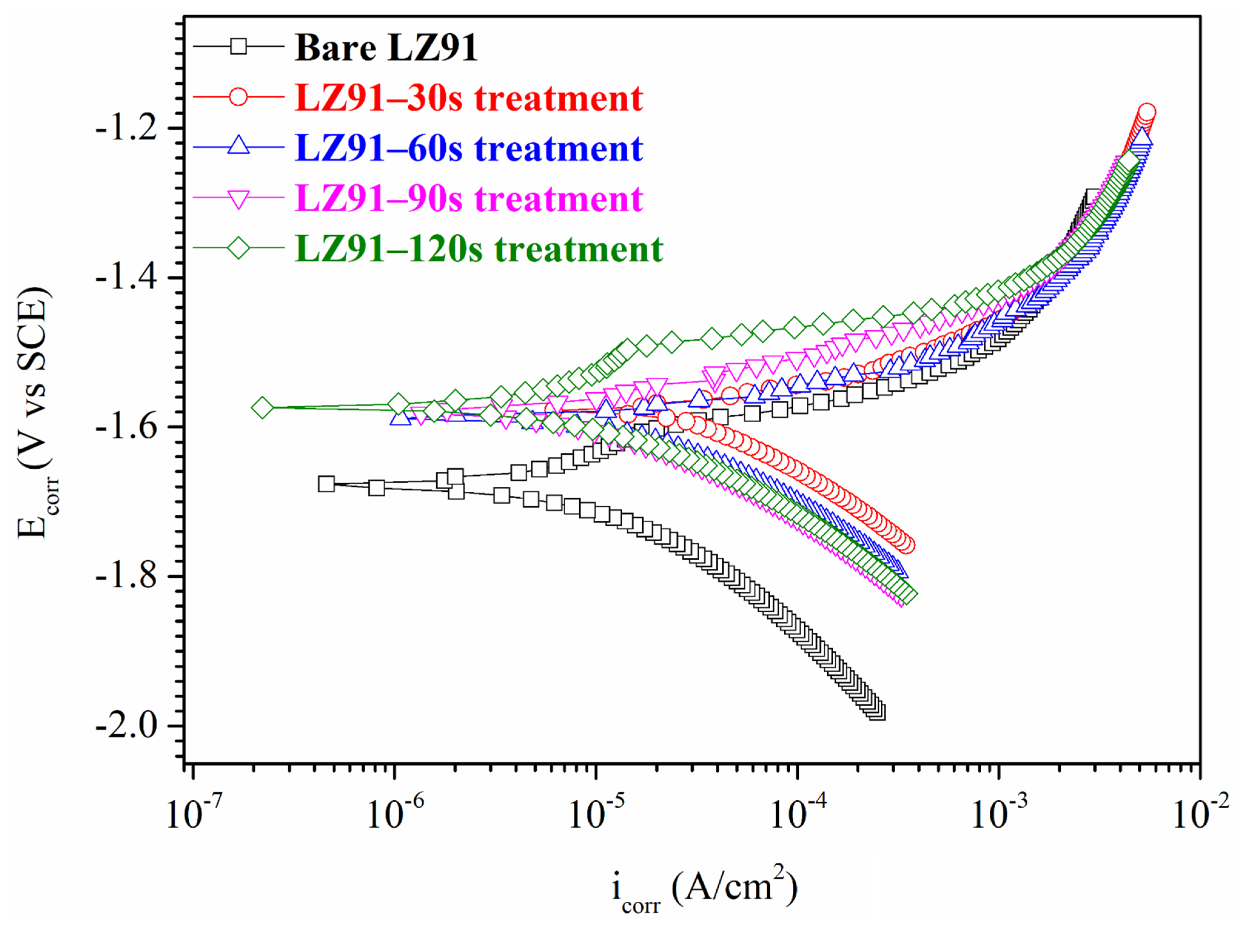
| Specimen | icorr (μA·cm−2) | Ecorr (V) |
|---|---|---|
| Bare LZ91 | 10.2 (±1.35) | −1.68 (±5.21 × 10⁻³) |
| 30 s | 44.0 (±2.71) | −1.58 (±6.46 × 10⁻³) |
| 60 s | 22.0 (±2.34) | −1.59 (±4.51 × 10⁻³) |
| 90 s | 14.5 (±2.01) | −1.58 (±5.19 × 10⁻³) |
| 120 s | 11.9 (±1.81) | −1.57 (±5.34 × 10⁻³) |
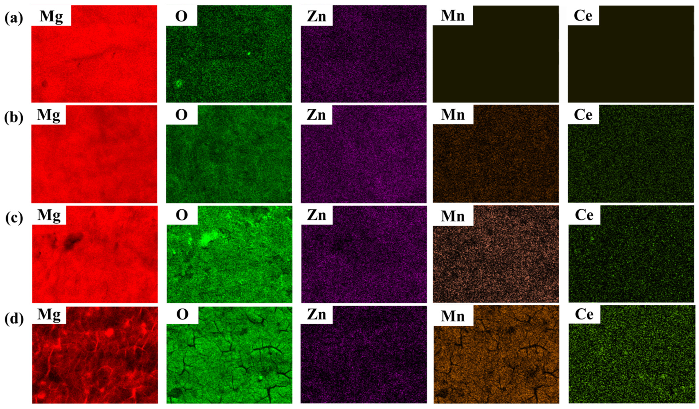
| Specimen | Mg | O | Zn | Mn | Ce | Others |
|---|---|---|---|---|---|---|
| 1 s | 94 | 5.6 | 0.4 | 0 | 0 | 0 |
| 5 s | 87.5 | 10.5 | 0.3 | 1.3 | 0.3 | 0.1 |
| 10 s | 80.6 | 16.3 | 0.3 | 2.5 | 0.4 | 0 |
| 30 s | 45.8 | 39.7 | 0.3 | 12.7 | 0.9 | 0.6 |
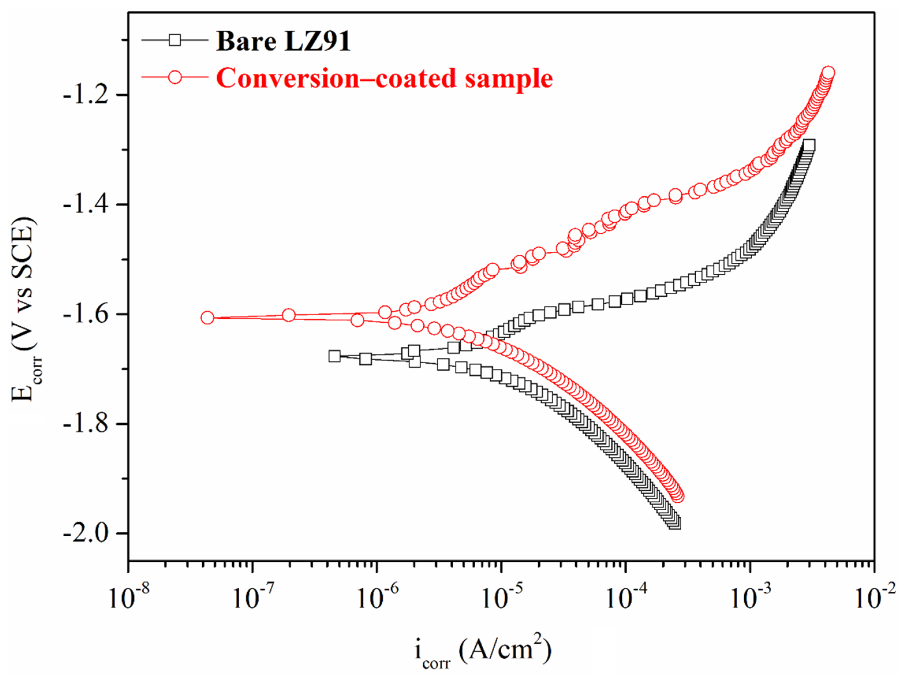
| Specimen | icorr (μA·cm−2) | Ecorr (V) |
|---|---|---|
| Bare LZ91 | 10.2 (±1.35) | −1.68 (±5.21 × 10⁻³) |
| Conversion-coated sample | 4.57 (±1.45) | −1.58 (±5.15 × 10⁻³) |
| Specimen | Dissolved Amount of Magnesium (mg/L) |
|---|---|
| Grinding pretreatment | 0.091 (±0.004) |
| Acid pickling pretreatment | 0.032 (±0.002) |
Publisher’s Note: MDPI stays neutral with regard to jurisdictional claims in published maps and institutional affiliations. |
© 2022 by the authors. Licensee MDPI, Basel, Switzerland. This article is an open access article distributed under the terms and conditions of the Creative Commons Attribution (CC BY) license (https://creativecommons.org/licenses/by/4.0/).
Share and Cite
Chen, C.-W.; Aktug, S.L.; Chang, C.-J.; Lee, Y.-L.; Ger, M.-D.; Jian, S.-Y. A Chromate-Free and Convenient Route to Fabricate Thin and Compact Conversion Coating for Corrosion Protection on LZ91 Magnesium Alloy. Nanomaterials 2022, 12, 1614. https://doi.org/10.3390/nano12091614
Chen C-W, Aktug SL, Chang C-J, Lee Y-L, Ger M-D, Jian S-Y. A Chromate-Free and Convenient Route to Fabricate Thin and Compact Conversion Coating for Corrosion Protection on LZ91 Magnesium Alloy. Nanomaterials. 2022; 12(9):1614. https://doi.org/10.3390/nano12091614
Chicago/Turabian StyleChen, Chun-Wei, Salim Levent Aktug, Chin-Jou Chang, Yueh-Lien Lee, Ming-Der Ger, and Shun-Yi Jian. 2022. "A Chromate-Free and Convenient Route to Fabricate Thin and Compact Conversion Coating for Corrosion Protection on LZ91 Magnesium Alloy" Nanomaterials 12, no. 9: 1614. https://doi.org/10.3390/nano12091614