
Enhancing the Melting Process of Shell-and-Tube PCM Thermal Energy Storage Unit Using Modified Tube Design
 , , , ,
  , , and
Abstract
:1. Introduction
2. Problem Description and Formulation
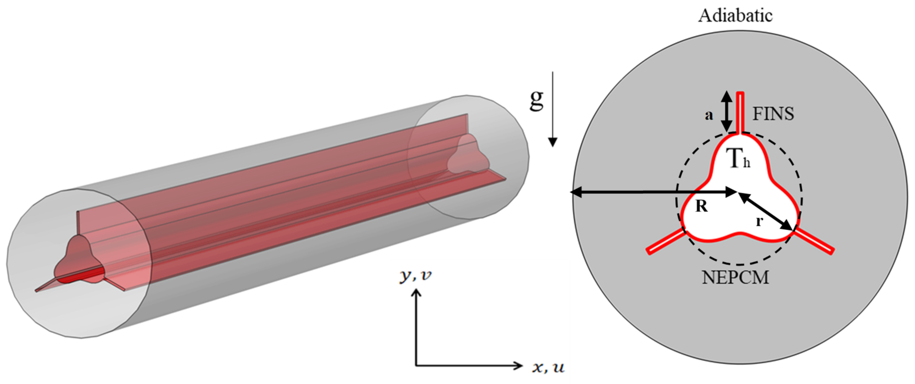
2.1. Physical Model

| Property | PCM (Liquid) | PCM (Solid) | Nanoparticles |
|---|---|---|---|
| Density (kg/m3) | 775 | 833.6 | 8954 |
| Specific heat (kJ/kg K) | 2.44 | 2.384 | 0.383 |
| Thermal conductivity (W/m K) | 0.15 | 0.39 | 400 |
| Melting temperature (K) | 327.15 | - | |
| Kinematic viscosity (m2/s) | 8.31 × 10⁻⁵ | - | |
| Latent heat of fusion (kJ/kg) | 184.48 | - | |
| Thermal expansion coefficient (K−1) | 7.14 × 10⁻³ | 67 × 10−5 | |
2.2. Initial and Boundary Conditions
3. Mathematical Model
- The flow of liquid NePCM is regarded to be incompressible and laminar.
- Because PCM’s physical characteristics stay largely constant during the phase shift, they may be considered constant.
- Ignoring the volumetric effect of viscous dissipation and sources of heat.
- Based on the above assumptions, the governing equation for the melting of NePCM in the wavy finned enclosure may be derived. The equations may be written as follows [47].
4. Results and Discussion
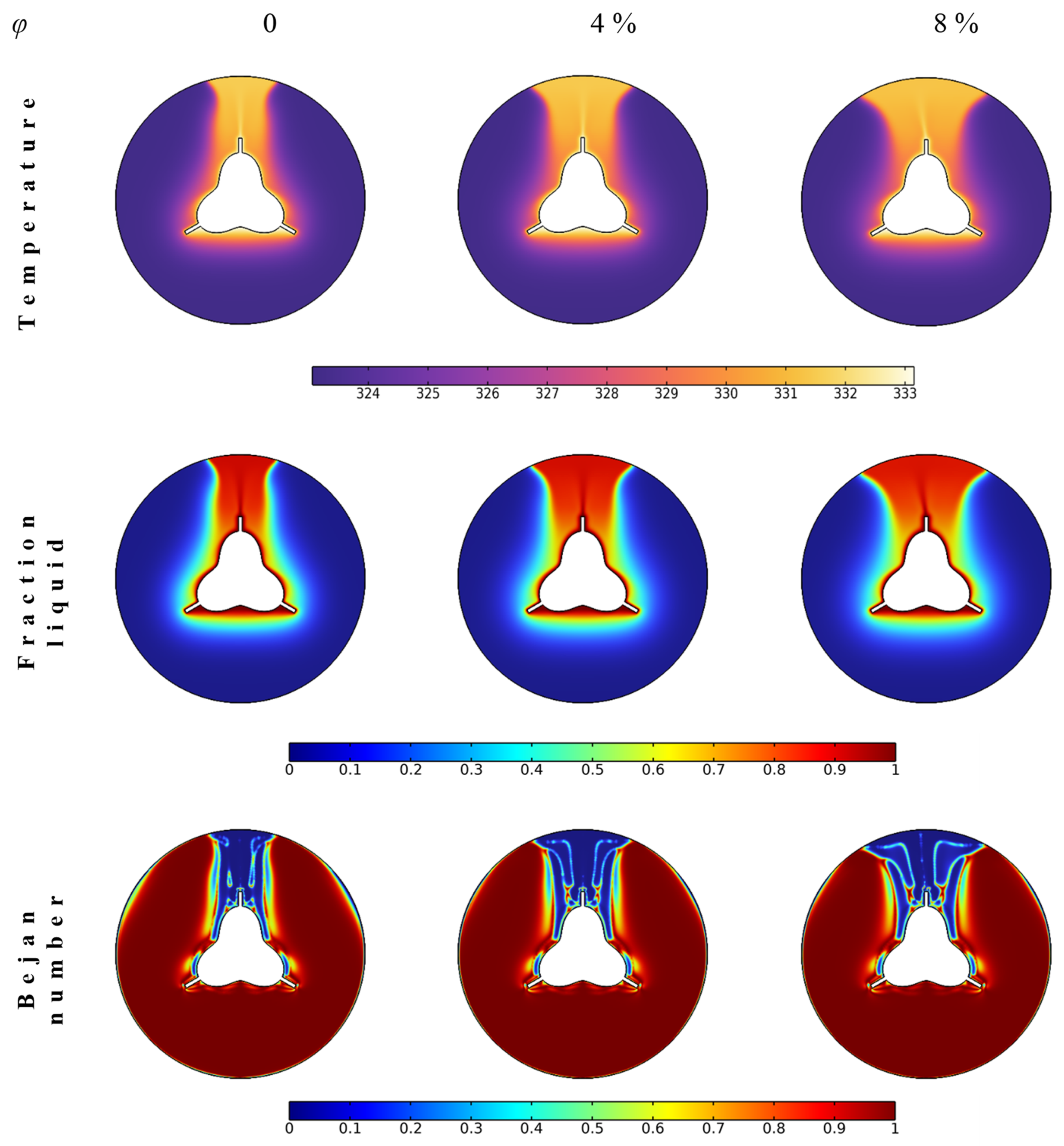
4.1. Nanoparticle Concentration
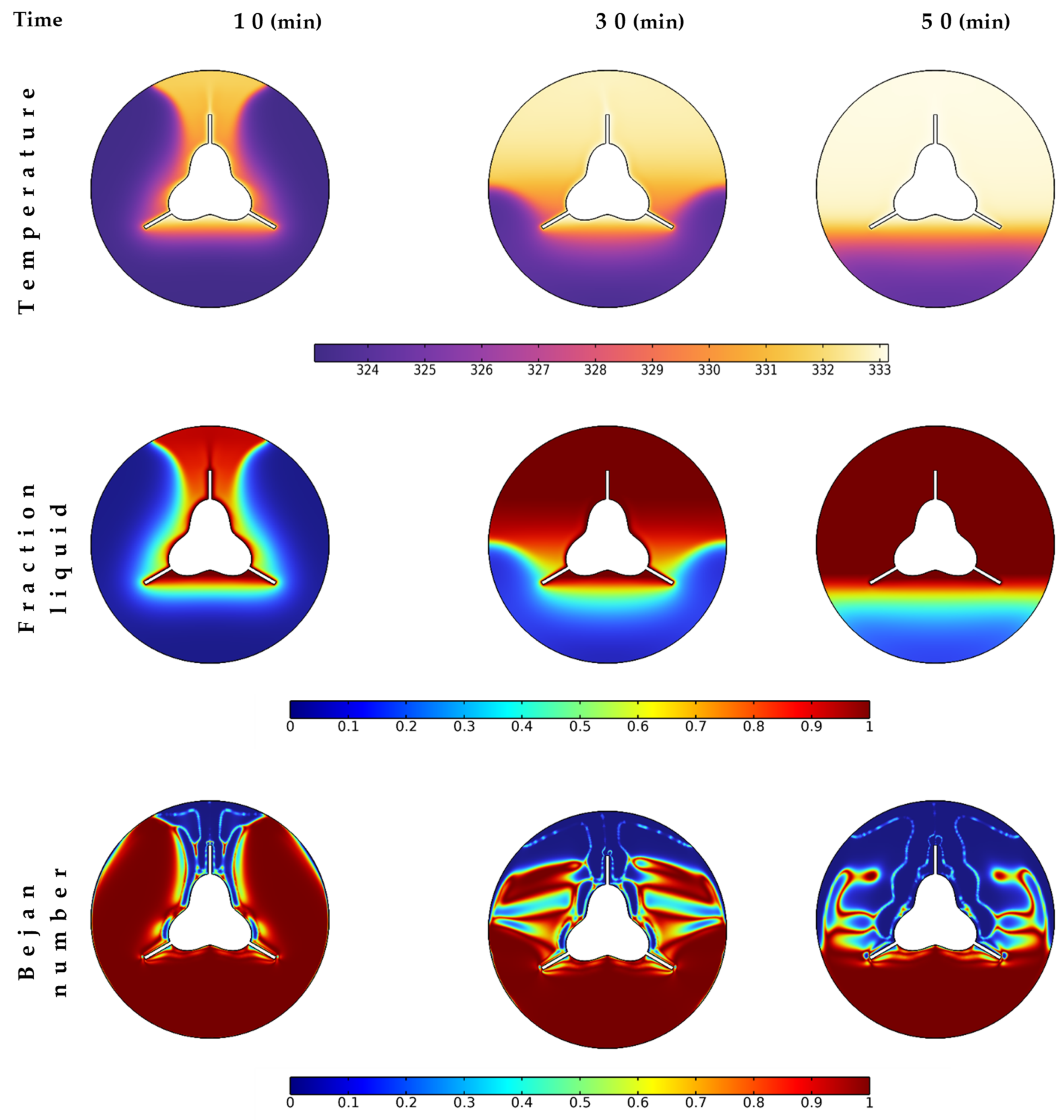
4.2. Melting Time
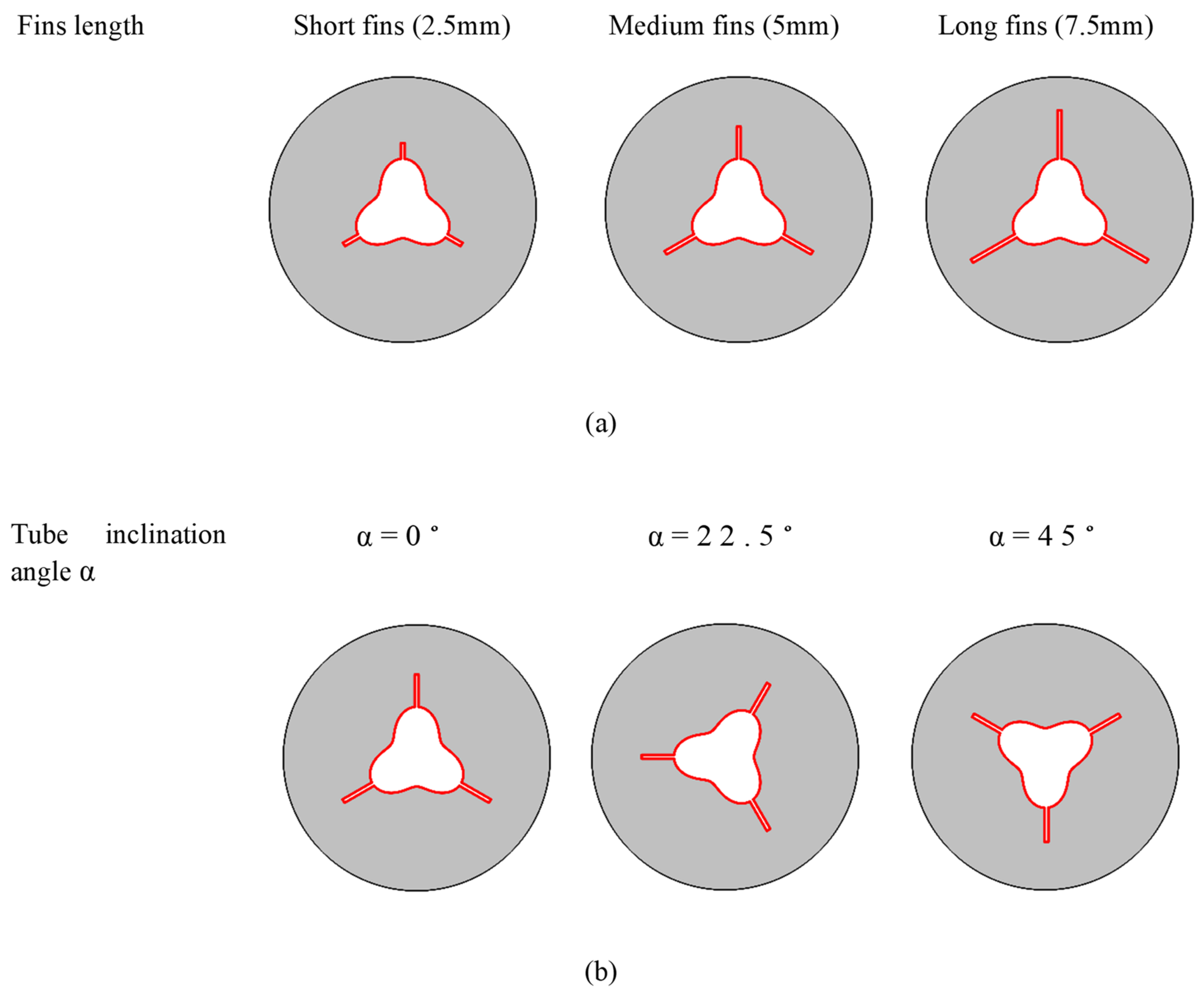
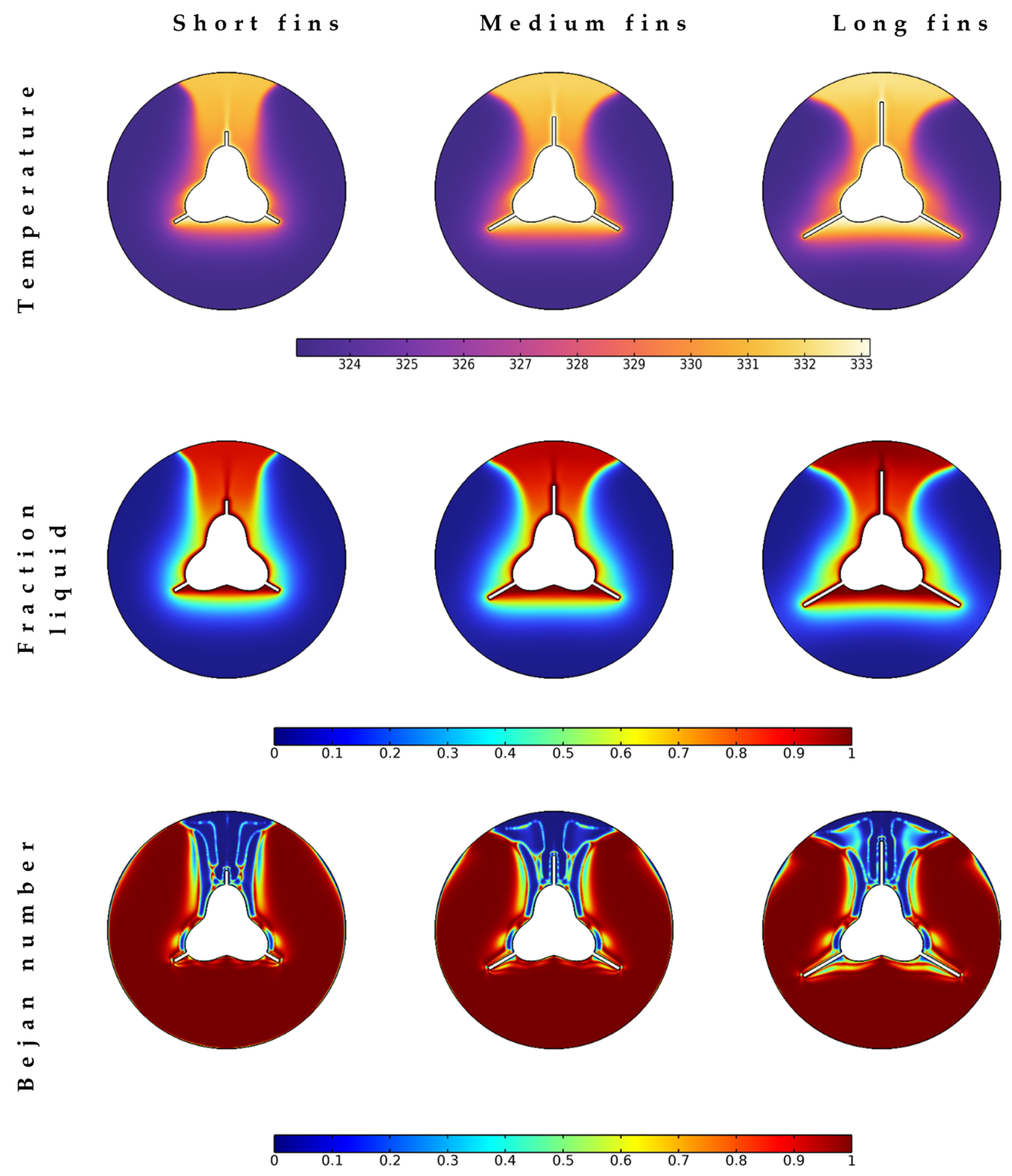
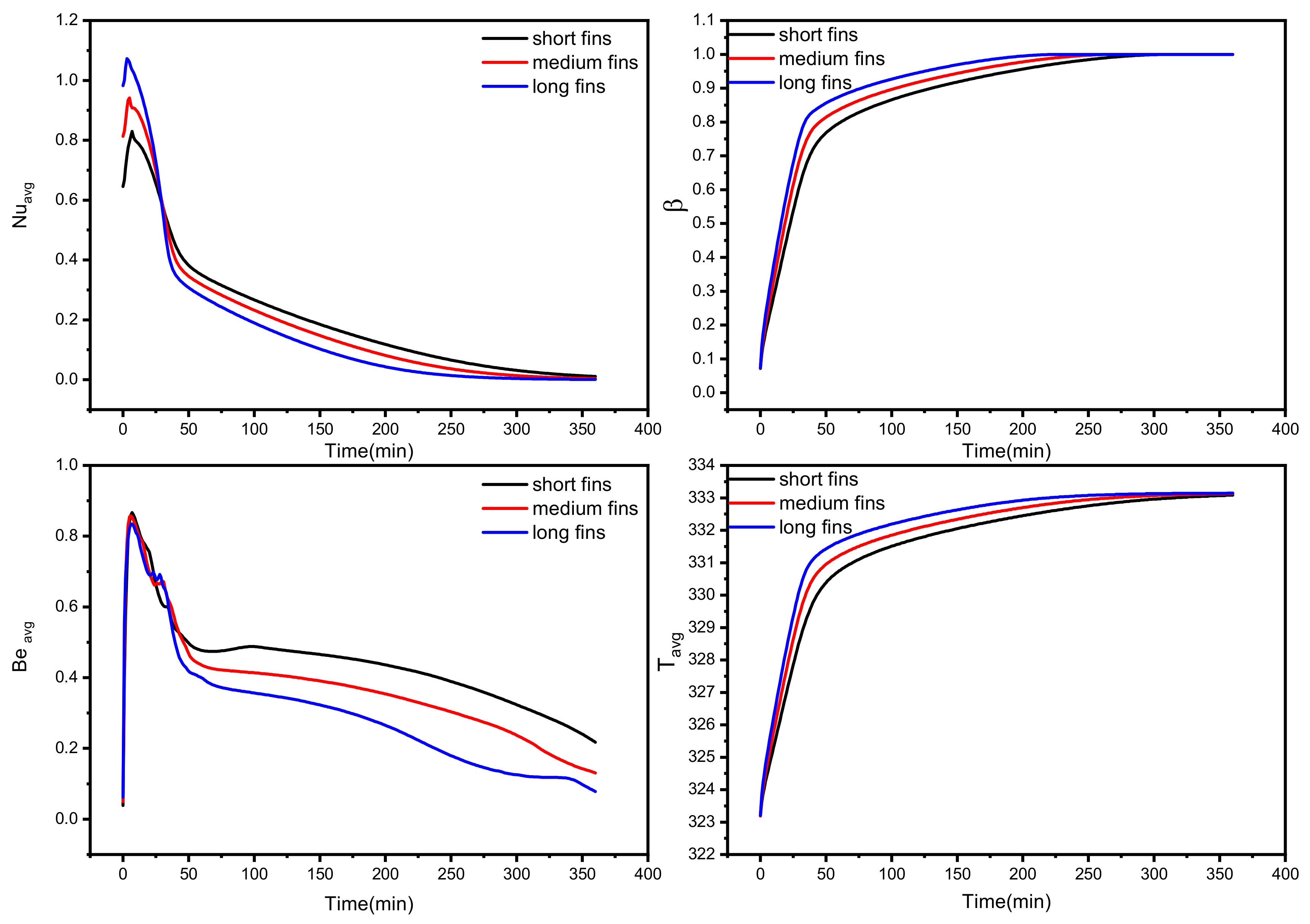
4.3. Fin Length
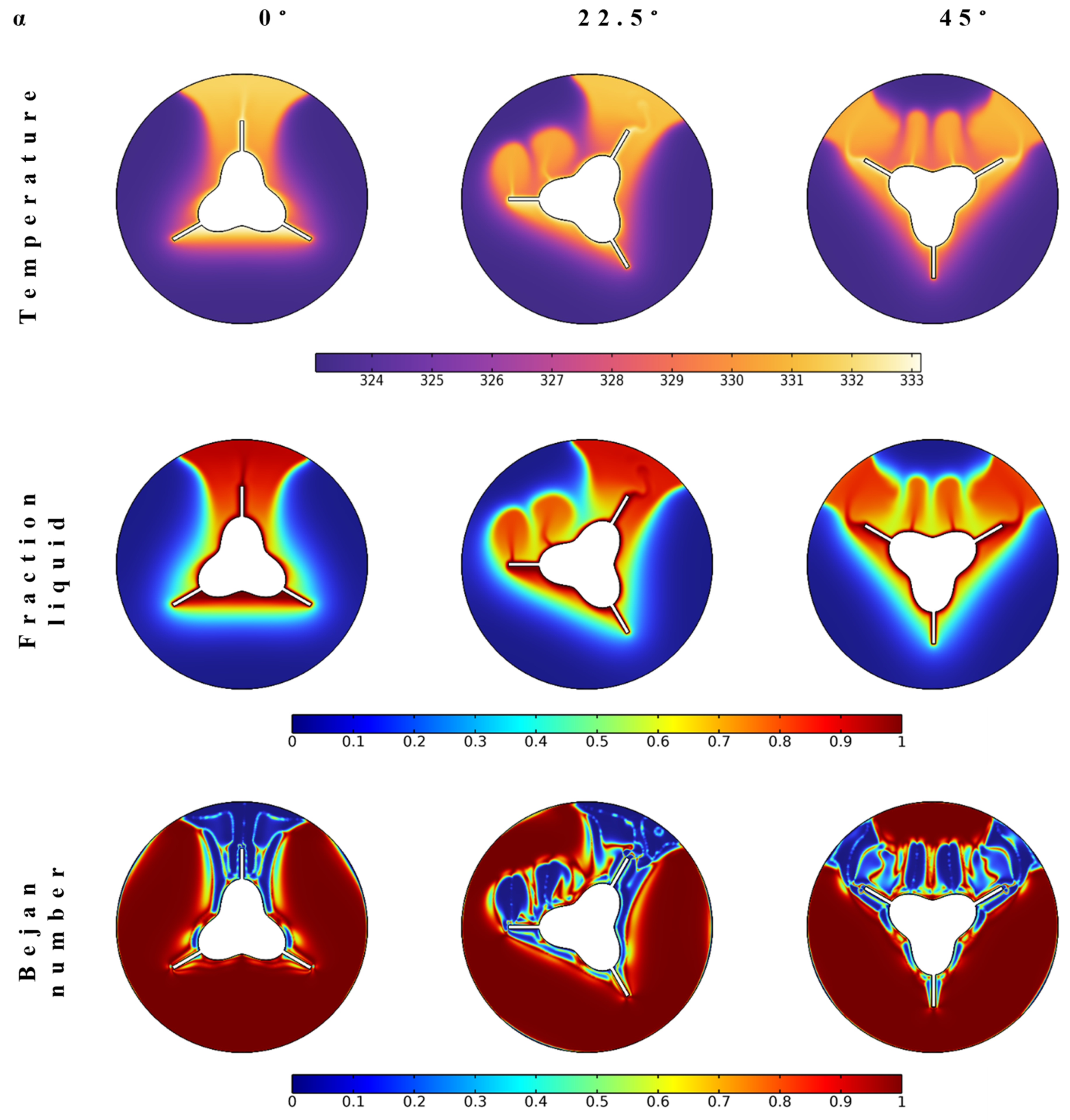
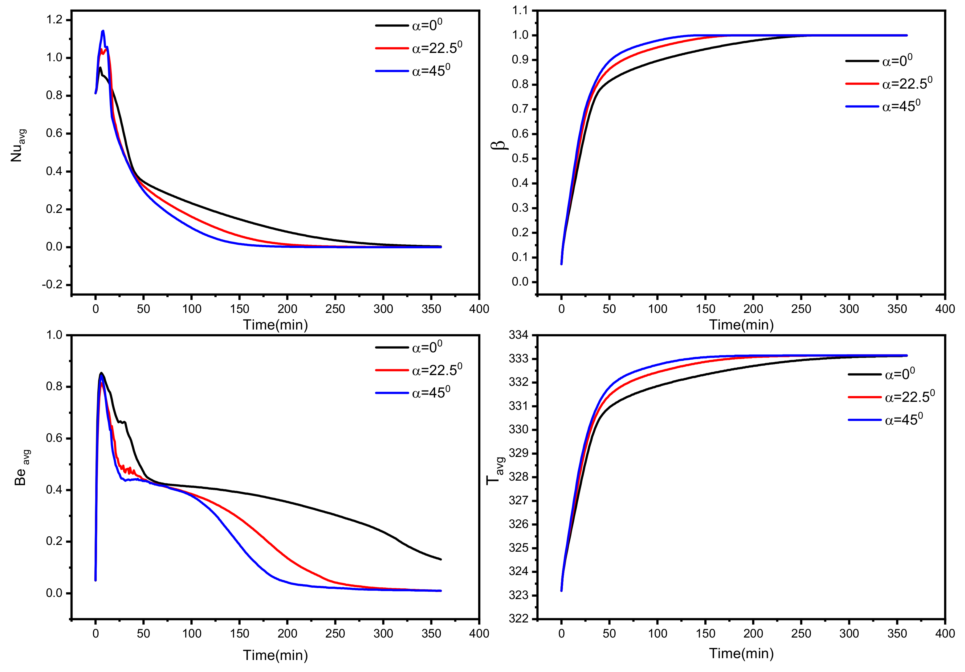
4.4. Inclination Angle
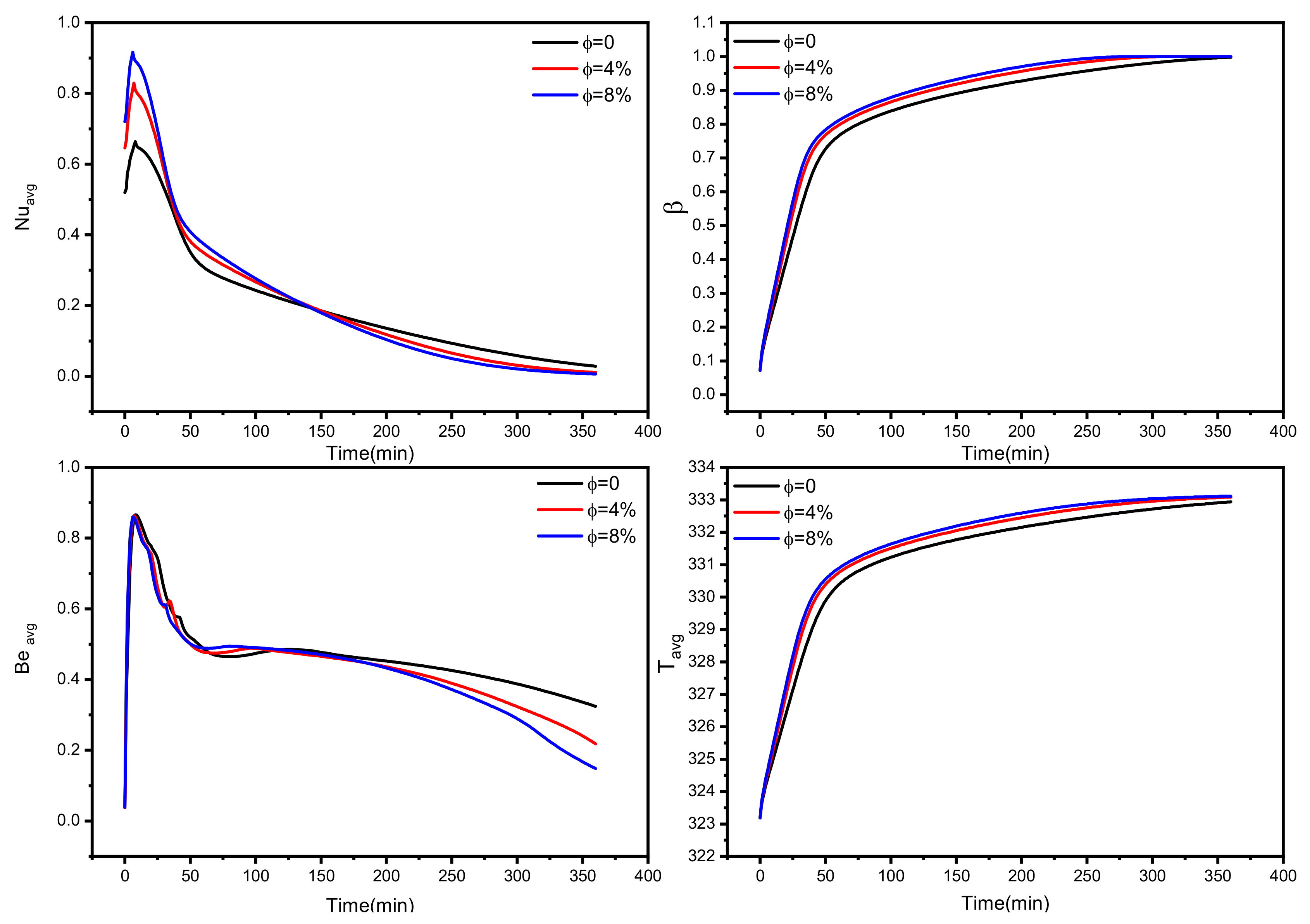
4.5. Temporal Performance of the Tube–Shell Unit
5. Conclusions
- Incorporating Cu nanoparticles with PCM materials enhances the thermal and melting performance and minimizes the entropy generation. The best results (with a 27% reduction in melting time) are found to be with the use of 8 vol% of nanoparticle concentration.
- Using long fins could enhance the heat transfer characteristics and reduce the melting time by about 40%.
- The orientation of the fins is crucial since they reach the bottom regions of the TES unit to benefit from the buoyancy effect. The position of the fins for 45° inclination could achieve a 50% expedition in the melting process.
- Based on the mentioned remarks, incorporating nanoparticles with PCM and using long fins in a proper position lead to an enhanced PCM melting process for the thermal energy storage units.
Author Contributions
Funding
Institutional Review Board Statement
Informed Consent Statement
Data Availability Statement
Acknowledgments
Conflicts of Interest
References
- Javadi, F.S.; Metselaar, H.S.C.; Ganesan, P. Performance improvement of solar thermal systems integrated with phase change materials (PCM), a review. Sol. Energy 2020, 206, 330–352. [Google Scholar] [CrossRef]
- Mourad, A.; Aissa, A.; Said, Z.; Younis, O.; Iqbal, M.; Alazzam, A. Recent advances on the applications of phase change materials for solar collectors, practical limitations, and challenges: A critical review. J. Energy Storage 2022, 49, 104186. [Google Scholar] [CrossRef]
- Abderrahmane, A.; Al-Khaleel, M.; Mourad, A.; Laidoudi, H.; Driss, Z.; Younis, O.; Guedri, K.; Marzouki, R. Natural Convection within Inversed T-Shaped Enclosure Filled by Nano-Enhanced Phase Change Material: Numerical Investigation. Nanomaterials 2022, 12, 2917. [Google Scholar] [CrossRef]
- Al-Kouz, W.; Aissa, A.; Devi, S.S.U.; Prakash, M.; Kolsi, L.; Moria, H.; Jamshed, W.; Younis, O. Effect of a rotating cylinder on the 3D MHD mixed convection in a phase change material filled cubic enclosure. Sustain. Energy Technol. Assess. 2022, 51, 101879. [Google Scholar] [CrossRef]
- Alehosseini, E.; Jafari, S.M. Nanoencapsulation of phase change materials (PCMs) and their applications in various fields for energy storage and management. Adv. Colloid Interface Sci. 2020, 283, 102226. [Google Scholar] [CrossRef]
- Kant, K.; Biwole, P.H.; Shamseddine, I.; Tlaiji, G.; Pennec, F.; Fardoun, F. Recent advances in thermophysical properties enhancement of phase change materials for thermal energy storage. Sol. Energy Mater. Sol. Cells 2021, 231, 111309. [Google Scholar] [CrossRef]
- Kunwer, R.; Bhurat, S.S. Thermal characterization of phase change materials (PCM) for heating applications. Mater. Today Proc. 2021, 50, 1690–1696. [Google Scholar] [CrossRef]
- Tan, P.; Lindberg, P.; Eichler, K.; Löveryd, P.; Johansson, P.; Kalagasidis, A.S. Effect of phase separation and supercooling on the storage capacity in a commercial latent heat thermal energy storage: Experimental cycling of a salt hydrate PCM. J. Energy Storage 2020, 29, 101266. [Google Scholar] [CrossRef]
- Moreno, P.; Miró, L.; Solé, A.; Barreneche, C.; Solé, C.; Martorell, I.; Cabeza, L.F. Corrosion of metal and metal alloy containers in contact with phase change materials (PCM) for potential heating and cooling applications. Appl. Energy 2014, 125, 238–245. [Google Scholar] [CrossRef]
- Ramakrishnan, S.; Sanjayan, J.; Wang, X.; Alam, M.; Wilson, J. A novel paraffin/expanded perlite composite phase change material for prevention of PCM leakage in cementitious composites. Appl. Energy 2015, 157, 85–94. [Google Scholar] [CrossRef]
- Zahir, M.H.; Mohamed, S.A.; Saidur, R.; Al-Sulaiman, F.A. Supercooling of phase-change materials and the techniques used to mitigate the phenomenon. Appl. Energy 2019, 240, 793–817. [Google Scholar] [CrossRef]
- Cheng, W.-L.; Mei, B.-J.; Liu, Y.-N.; Huang, Y.-H.; Yuan, X.-D. A novel household refrigerator with shape-stabilized PCM (Phase Change Material) heat storage condensers: An experimental investigation. Energy 2011, 36, 5797–5804. [Google Scholar] [CrossRef]
- Xu, X.; Zhang, Y.; Lin, K.; Di, H.; Yang, R. Modeling and simulation on the thermal performance of shape-stabilized phase change material floor used in passive solar buildings. Energy Build. 2005, 37, 1084–1091. [Google Scholar] [CrossRef]
- Choi, D.H.; Lee, J.; Hong, H.; Kang, Y.T. Thermal conductivity and heat transfer performance enhancement of phase change materials (PCM) containing carbon additives for heat storage application. Int. J. Refrig. 2014, 42, 112–120. [Google Scholar] [CrossRef]
- Pourakabar, A.; Rabienataj Darzi, A.A. Enhancement of phase change rate of PCM in cylindrical thermal energy storage. Appl. Therm. Eng. 2019, 150, 132–142. [Google Scholar] [CrossRef]
- Rathore, P.K.S.; Shukla, S.K. Enhanced thermophysical properties of organic PCM through shape stabilization for thermal energy storage in buildings: A state of the art review. Energy Build. 2021, 236, 110799. [Google Scholar] [CrossRef]
- Zhang, H.; Wang, L.; Xi, S.; Xie, H.; Yu, W. 3D porous copper foam-based shape-stabilized composite phase change materials for high photothermal conversion, thermal conductivity and storage. Renew. Energy 2021, 175, 307–317. [Google Scholar] [CrossRef]
- Koulali, A.; Abderrahmane, A.; Jamshed, W.; Hussain, S.M.; Nisar, K.S.; Abdel-Aty, A.-H.; Yahia, I.S.; Eid, M.R. Comparative Study on Effects of Thermal Gradient Direction on Heat Exchange between a Pure Fluid and a Nanofluid: Employing Finite Volume Method. Coatings 2021, 11, 1481. [Google Scholar] [CrossRef]
- Rasool, G.; Saeed, A.M.; Lare, A.I.; Abderrahmane, A.; Guedri, K.; Vaidya, H.; Marzouki, R. Darcy-Forchheimer Flow of Water Conveying Multi-Walled Carbon Nanoparticles through a Vertical Cleveland Z-Staggered Cavity Subject to Entropy Generation. Micromachines 2022, 13, 744. [Google Scholar] [CrossRef]
- Abderrahmane, A.; Qasem, N.A.A.; Younis, O.; Marzouki, R.; Mourad, A.; Shah, N.A.; Chung, J.D. MHD Hybrid Nanofluid Mixed Convection Heat Transfer and Entropy Generation in a 3-D Triangular Porous Cavity with Zigzag Wall and Rotating Cylinder. Mathematics 2022, 10, 769. [Google Scholar] [CrossRef]
- Al-Kouz, W.; Medebber, M.A.; Elkotb, M.A.; Abderrahmane, A.; Aimad, K.; Al-Farhany, K.; Jamshed, W.; Moria, H.; Aldawi, F.; Saleel, C.A.; et al. Galerkin finite element analysis of Darcy–Brinkman–Forchheimer natural convective flow in conical annular enclosure with discrete heat sources. Energy Rep. 2021, 7, 6172–6181. [Google Scholar] [CrossRef]
- Seddegh, S.; Wang, X.; Joybari, M.M.; Haghighat, F. Investigation of the effect of geometric and operating parameters on thermal behavior of vertical shell-and-tube latent heat energy storage systems. Energy 2017, 137, 69–82. [Google Scholar] [CrossRef]
- Zayed, M.E.; Zhao, J.; Li, W.; Elsheikh, A.; Elbanna, A.M.; Jing, L.; Geweda, A. Recent progress in phase change materials storage containers: Geometries, design considerations and heat transfer improvement methods. J. Energy Storage 2020, 30, 101341. [Google Scholar] [CrossRef]
- Khanna, S.; Singh, P.; Mudgal, V.; Newar, S.; Sharma, V.; Becerra, V.; Reddy, K.; Mallick, T.K. Novel thermal conductivity enhancing containers for performance enhancement of solar photovoltaics system integrated with phase change material. Energy 2021, 243, 122923. [Google Scholar] [CrossRef]
- Sathe, T.; Dhoble, A. Thermal analysis of an inclined heat sink with finned PCM container for solar applications. Int. J. Heat Mass Transf. 2019, 144, 118679. [Google Scholar] [CrossRef]
- Mehryan, S.A.M.; Ayoubi-Ayoubloo, K.; Shahabadi, M.; Ghalambaz, M.; Talebizadehsardari, P.; Chamkha, A. Conjugate Phase Change Heat Transfer in an Inclined Compound Cavity Partially Filled with a Porous Medium: A Deformed Mesh Approach. Transp. Porous Media 2020, 132, 657–681. [Google Scholar] [CrossRef]
- Iasiello, M.; Mameli, M.; Filippeschi, S.; Bianco, N. Metal foam/PCM melting evolution analysis: Orientation and morphology effects. Appl. Therm. Eng. 2021, 187, 116572. [Google Scholar] [CrossRef]
- Pu, L.; Zhang, S.; Xu, L.; Ma, Z.; Wang, X. Numerical study on the performance of shell-and-tube thermal energy storage using multiple PCMs and gradient copper foam. Renew. Energy 2021, 174, 573–589. [Google Scholar] [CrossRef]
- Esapour, M.; Hamzehnezhad, A.; Darzi, A.A.R.; Jourabian, M. Melting and solidification of PCM embedded in porous metal foam in horizontal multi-tube heat storage system. Energy Convers. Manag. 2018, 171, 398–410. [Google Scholar] [CrossRef]
- Mahdi, J.M.; Nsofor, E. Multiple-segment metal foam application in the shell-and-tube PCM thermal energy storage system. J. Energy Storage 2018, 20, 529–541. [Google Scholar] [CrossRef]
- Zhao, C.Y.; Zhou, D.; Wu, Z.G. Heat transfer of phase change materials (PCMs) in porous materials. Front. Energy 2011, 5, 174–180. [Google Scholar] [CrossRef]
- Bayat, M.; Faridzadeh, M.R.; Toghraie, D. Investigation of finned heat sink performance with nano enhanced phase change material (NePCM). Therm. Sci. Eng. Prog. 2018, 5, 50–59. [Google Scholar] [CrossRef]
- Suraparaju, S.K.; Natarajan, S.K. Experimental investigation of single-basin solar still using solid staggered fins inserted in paraffin wax PCM bed for enhancing productivity. Environ. Sci. Pollut. Res. 2021, 28, 20330–20343. [Google Scholar] [CrossRef]
- Abu-Hamdeh, N.H.; Abusorrah, A.M.; Hosseini, F.; Bayoumi, M.M.; Oztop, H.F. Sensitivity analysis on thermophysical properties efficacy on PCM-based heat sink usefulness: Effects of solid particles versus liquid phase fraction. J. Therm. Anal. 2021, 144, 2699–2708. [Google Scholar] [CrossRef]
- Leong, K.Y.; Rahman, M.R.A.; Gurunathan, B.A. Nano-enhanced phase change materials: A review of thermo-physical properties, applications and challenges. J. Energy Storage 2019, 21, 18–31. [Google Scholar] [CrossRef]
- Laouer, A.; Arıcı, M.; Teggar, M.; Bouabdallah, S.; Yıldız, Ç.; Ismail, K.A.; Ajarostaghi, S.S.M.; Mezaache, E.H. Effect of Magnetic Field and Nanoparticle Concentration on Melting of Cu-Ice in a Rectangular Cavity under Fluctuating Temperatures. J. Energy Storage 2021, 36, 102421. [Google Scholar] [CrossRef]
- Zhuang, Y.; Liu, Z.; Xu, W. Experimental investigation on the non-Newtonian to Newtonian rheology transition of nanoparticles enhanced phase change material during melting. Colloids Surf. A Physicochem. Eng. Asp. 2021, 629, 127432. [Google Scholar] [CrossRef]
- Kumar, K.R.S.; Kalaiselvam, S. Experimental investigations on the thermophysical properties of CuO-palmitic acid phase change material for heating applications. J. Therm. Anal. 2017, 129, 1647–1657. [Google Scholar] [CrossRef]
- Sheikholeslami, M. Finite element method for PCM solidification in existence of CuO nanoparticles. J. Mol. Liq. 2018, 265, 347–355. [Google Scholar] [CrossRef]
- Thangam, A.; Auckaili, A.; Farid, M. Combination of Passive and Active Solar Heating with Thermal Energy Storage. Molecules 2022, 27, 4386. [Google Scholar] [CrossRef]
- Santiago-Acosta, R.D.; Hernández-Cooper, E.M.; Pérez-Álvarez, R.; Otero, J.A. Effects of Volume Changes on the Thermal Performance of PCM Layers Subjected to Oscillations of the Ambient Temperature: Transient and Steady Periodic Regimes. Molecules 2022, 27, 2158. [Google Scholar] [CrossRef] [PubMed]
- Ghalambaz, M.; Mehryan, S.; Ayoubloo, K.; Hajjar, A.; El Kadri, M.; Younis, O.; Pour, M.; Hulme-Smith, C. Thermal Energy Storage and Heat Transfer of Nano-Enhanced Phase Change Material (NePCM) in a Shell and Tube Thermal Energy Storage (TES) Unit with a Partial Layer of Eccentric Copper Foam. Molecules 2021, 26, 1491. [Google Scholar] [CrossRef] [PubMed]
- Mahani, R.B.; Mohammed, H.I.; Mahdi, J.M.; Alamshahi, F.; Ghalambaz, M.; Talebizadehsardari, P.; Yaïci, W. Phase Change Process in a Zigzag Plate Latent Heat Storage System during Melting and Solidification. Molecules 2020, 25, 4643. [Google Scholar] [CrossRef] [PubMed]
- Yimin, X.; Roetzel, W. Conceptions for heat transfer correlation of nanofluids. Int. J. Heat Mass Transf. 2000, 43, 3701–3707. [Google Scholar]
- Mourad, A.; Abderrahmane, A.; Younis, O.; Marzouki, R.; Alazzam, A. Numerical Simulations of Magnetohydrodynamics Natural Convection and Entropy Production in a Porous Annulus Bounded by Wavy Cylinder and Koch Snowflake Loaded with Cu–Water Nanofluid. Micromachines 2022, 13, 182. [Google Scholar] [CrossRef] [PubMed]
- Thirugnanam, C.; Marimuthu, P. Experimental Analysis of Latent Heat Thermal Energy Storage using Paraffin Wax as Phase Change Material. Int. J. Eng. Innov. Technol. 2013, 3, 372. [Google Scholar]
- Al-Khaleel, M.D.; Gander, M.J.; Ruehli, A.E. Optimized waveform relaxation solution of RLCG transmission line type circuits. In Proceedings of the 9th International Conference on Innovations in Information Technology, IIT 2013, Al Ain, United Arab Emirates, 17–19 March 2013; pp. 136–140. [Google Scholar]
- Wu, S.-L.; Al-Khaleel, M.D. Semi-discrete Schwarz waveform relaxation algorithms for reaction diffusion equations. BIT Numer. Math. 2014, 54, 831–866. [Google Scholar] [CrossRef]
- Wu, S.-L.; Al-Khaleel, M. Convergence analysis of the Neumann–Neumann waveform relaxation method for time-fractional RC circuits. Simul. Model. Pract. Theory 2016, 64, 43–56. [Google Scholar] [CrossRef]
- Wu, S.-L.; Al-Khaleel, M.D. Optimized waveform relaxation methods for RC circuits: Discrete case. ESAIM Math. Model. Numer. Anal. 2017, 51, 209–223. [Google Scholar] [CrossRef]
- Ahmed, S.E.; Abderrahmane, A.; Alotaibi, S.; Younis, O.; Almasri, R.A.; Hussam, W.K. Enhanced Heat Transfer for NePCM-Melting-Based Thermal Energy of Finned Heat Pipe. Nanomaterials 2022, 12, 129. [Google Scholar] [CrossRef] [PubMed]
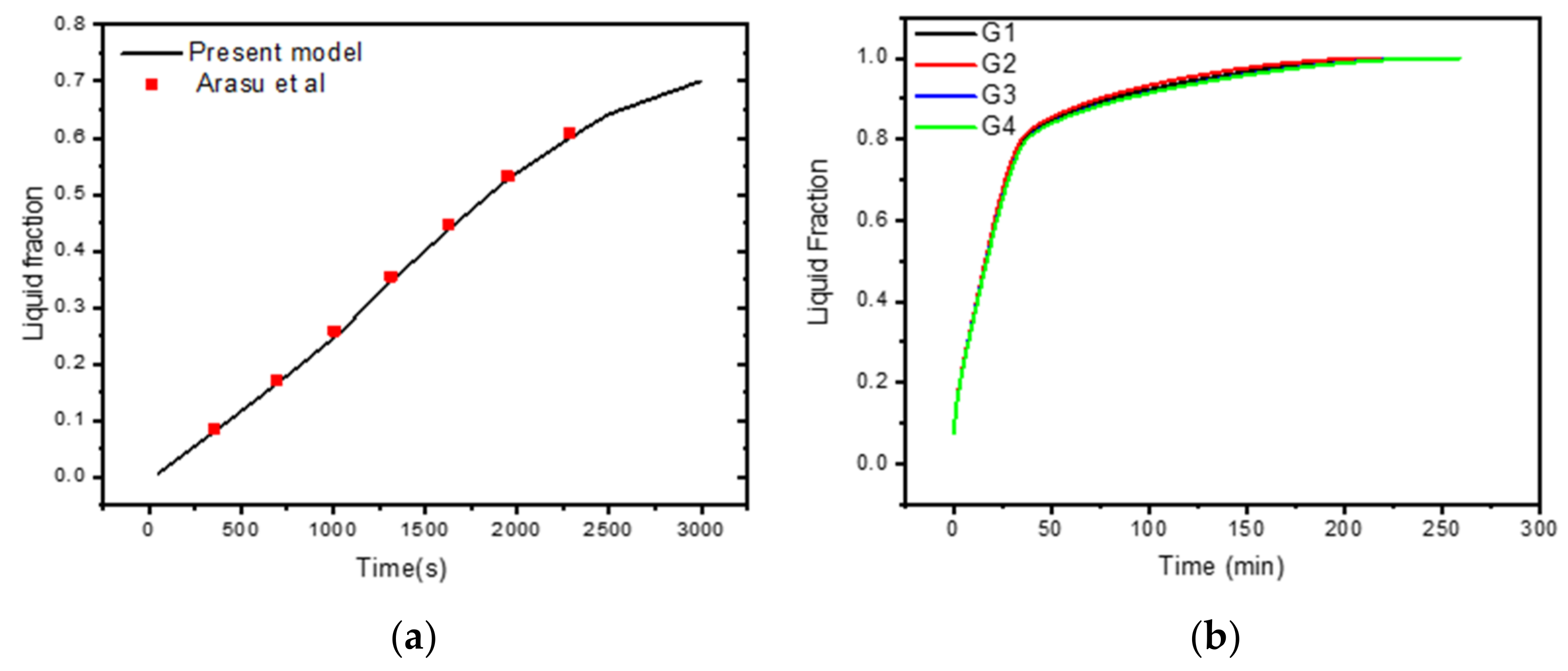
- Arasu, A.V.; Mujumdar, A.S. Numerical study on melting of paraffin wax with Al2O3 in a square enclosure. Int. Commun. Heat Mass Transf. 2012, 39, 8–16. [Google Scholar] [CrossRef]


| Mesh | G1 | G2 | G3 | G4 |
|---|---|---|---|---|
| Number of Elements | 25,496 | 30,772 | 58,662 | 81,967 |
Publisher’s Note: MDPI stays neutral with regard to jurisdictional claims in published maps and institutional affiliations. |
© 2022 by the authors. Licensee MDPI, Basel, Switzerland. This article is an open access article distributed under the terms and conditions of the Creative Commons Attribution (CC BY) license (https://creativecommons.org/licenses/by/4.0/).
Share and Cite
Abderrahmane, A.; Qasem, N.A.A.; Mourad, A.; Al-Khaleel, M.; Said, Z.; Guedri, K.; Younis, O.; Marzouki, R. Enhancing the Melting Process of Shell-and-Tube PCM Thermal Energy Storage Unit Using Modified Tube Design. Nanomaterials 2022, 12, 3078. https://doi.org/10.3390/nano12173078
Abderrahmane A, Qasem NAA, Mourad A, Al-Khaleel M, Said Z, Guedri K, Younis O, Marzouki R. Enhancing the Melting Process of Shell-and-Tube PCM Thermal Energy Storage Unit Using Modified Tube Design. Nanomaterials. 2022; 12(17):3078. https://doi.org/10.3390/nano12173078
Chicago/Turabian StyleAbderrahmane, Aissa, Naef A. A. Qasem, Abed Mourad, Mohammad Al-Khaleel, Zafar Said, Kamel Guedri, Obai Younis, and Riadh Marzouki. 2022. "Enhancing the Melting Process of Shell-and-Tube PCM Thermal Energy Storage Unit Using Modified Tube Design" Nanomaterials 12, no. 17: 3078. https://doi.org/10.3390/nano12173078