Article

A Facile Fabrication of Ordered Mesoporous Carbons Derived from Phenolic Resin and Mesophase Pitch via a Self-Assembly Method

1
Convergence Research Division, Korea Carbon Industry Promotion Agency (KCARBON), 110-11 Banryong-ro, Deokjin-gu, Jeonju-si 54853, Jeollabuk-do, Korea
2
Department of Nano Convergence Engineering, Jeonbuk National University, 567 Baekje-daero, Deokjin-gu, Jeonju-si 54896, Jeollabuk-do, Korea
3
Department of Organic Materials & Fiber Engineering, Jeonbuk National University, 567 Baekje-daero, Deokjin-gu, Jeonju-si 54896, Jeollabuk-do, Korea
*
Authors to whom correspondence should be addressed.
These authors contributed equally to this work.
Nanomaterials 2022, 12(15), 2686; https://doi.org/10.3390/nano12152686
Submission received: 2 July 2022 / Revised: 29 July 2022 / Accepted: 3 August 2022 / Published: 4 August 2022
(This article belongs to the Special Issue Advanced Porous Nanomaterials: Synthesis, Properties, and Application)

Abstract

:
Ordered and disordered mesoporous structures were synthesized by a self-assembly method using a mixture of phenolic resin and petroleum-based mesophase pitch as the starting materials, amphiphilic triblock copolymer F127 as a soft template, hydrochloric acid as a catalyst, and distilled water as a solvent. Then, mesoporous carbons were obtained via autoclave method at low temperature (60 °C) and then carbonization at a relatively low temperature (600 °C), respectively. X-ray diffraction (XRD), small-angle X-ray scattering (SAXS), and transmission electron microscopy (TEM) analyses revealed that the porous carbons with a mesophase pitch content of approximately 10 wt% showed a highly ordered hexagonal mesostructure with a highly uniform pore size of ca. 5.0 nm. In addition, the mesoporous carbons prepared by self-assembly and low-temperature autoclave methods exhibited the amorphous or crystalline carbon structures with higher specific surface area (SSA) of 756 m2/s and pore volume of 0.63 cm3/g, depending on the synthesis method. As a result, mesoporous carbons having a high SSA were successfully prepared by changing the mixing ratio of mesophase pitch and phenolic resin. The electrochemical properties of as-obtained mesoporous carbon materials were investigated. Further, the OMC-meso-10 electrode delivered the maximum SC of about 241 F/g at an applied current density of 1 A/g, which was higher than those of the MC-10 (~104 F/g) and OMC-20 (~115 F/g).

Graphical Abstract

1. Introduction

An electric double-layer capacitor (EDLC) or a supercapacitor (SC) as a sustainable and renewable energy resource has given significant focus due to its excellent power density, superior cycle life, and rapid discharge/charge rate, etc., which can supplement secondary batteries [1,2,3,4]. Activated carbon (AC) is mainly used as an active material for EDLCs fabrication due to its large specific surface area and low cost. However, AC has a low electrical conductivity of 0.1–1 S cm−1, which increases the internal resistance of the EDLCs. Moreover, AC mainly contains micropore (<2 nm), which restricts access to electrolytes, because of large ionic sizes of organic electrolytes [5,6].
Ordered mesoporous carbon (OMC) materials show many attractive properties including good conductivity, electrochemical properties, tunable pore structure, and high specific surface area (up to 1100 m2 g−1), and can be therefore considered as a favorable electrode material for EDLCs [7,8,9,10]. OMC has been extensively studied for its potential usages in sorption, catalysis, supercapacitors, and electrocatalysts. To date, OMCs with different mesoporous structures have been effectively synthesized by both hard and soft template methods. However, the main drawbacks of the hard-template method are that it requires multiple steps for scaffold preparation and needs to use sacrificial surfactant templates as scaffolds. The high cost and complex synthesis of OMCs significantly have brought restrictions on application. In contrast, the soft-template method, in which amphiphilic surfactant compounds such as block copolymers are used as soft templates based on the principle of liquid-crystal templating, can produce OMC in a more flexible manner [11,12,13]. Recently, mesophase pitches have been applied as carbon sources to prepare mesoporous carbon (MC) materials. Compared with other carbon precursors, mesophase pitches can produce high-quality graphitized carbon. Generally, the pitch powders were mixed with a soft template and phenol resin at a slightly higher temperature than the softening points. In this case, the pitch particles were self-assembled into the template to form mesoporous composites. Finally, the mesoporous carbon was derived after the elimination of the template [14,15,16,17].
In this study, OMC and disordered MC were obtained by an organic–organic self-assembly process using a mixture of phenol resin and petroleum-based mesophase pitch as the carbon precursors at a low-temperature autoclave (LTA), and subsequently carbonized. The crystalline structures, textural properties, and electrochemical performances were investigated.

2. Materials and Methods

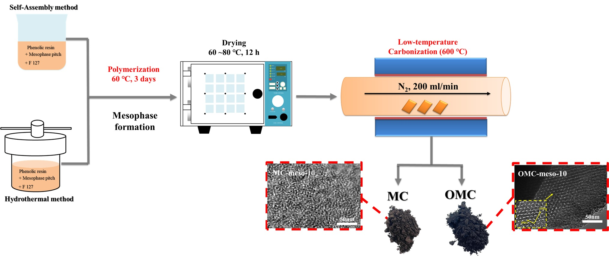
2.1. Preparation of Mesoporous Carbons

OMCs were synthesized by LTA method. First, 3.20 g of phenolic resin powder (CB-8081, Kangnam Chemical. Co., Ltd., Seoul, Korea) and 4.8 g of F127 (poly(ethylene glycol)-block-poly(propylene glycol)-block-poly(ethylene glycol) diacrylate, Sigma-Aldrich, St. Louis, MO, USA) were added in mixed solvent (80 mL, 1:1 water/ethanol, v/v) and stirred for 60 min to obtain clear solution. Then, 0.387 g of 37% HCl solution and different amounts (0, 10, 20 wt%) of mesophase pitch [17] were added to the above solution. The physical properties and elemental composition of the mesophase pitch used in this work are presented in Table 1. After stirring for 1 h, 37% formaldehyde (4.8 g, Sigma-Aldrich, St. Louis, MO, USA) solution was injected slowly under stirring. It continued to be stirred until a yellowish homogeneous solution was obtained. Then, it was poured into a Teflon-lined autoclave reactor and kept in electric oven for 3 days at 60 °C. The obtained polymeric monolith was collected by filtration, washed with deionized water, dehydrated in an oven at 60 °C, and further retained at 80 °C for 12 h, which led to a color change of the polymeric monolith into salmon pink. Subsequently, the products were carbonized in a tubular furnace under an inert atmosphere (N2 flow) by heating the products at a heating rate of 1 °C/min up to 600 °C and then maintained further for 6 h. Here, it should be noted that soft template was easily removed by conventional calcination at 600 °C [18,19]. The final products were denoted as OMC-meso-x (here, x denotes the amount of mesophase pitch used. x = 0, 10, 20 wt%). The type of precursors and synthesis conditions are presented in Table 2.
For comparison, MC samples were also prepared by an evaporation-induced self-assembly (EISA) method, except that the uniform yellowish solution was poured into the molds of various shapes and further retained at ambient temperature for 3 days to evaporate the ethanol. The other conditions of synthesis were the same as above. The obtained monolith showed a dark red color and was carbonized at 600 °C for 6 h at a heating rate of 1 °C/min. The carbonized products were designated as MC-meso-x, as above. The schematic of the synthesis preparation was shown in Figure 1.

2.2. Characterization

Powder X-ray diffraction (XRD) analysis was performed under a PANalytical NLD diffractometer at a scanning rate of 2°/min. Small-angle X-ray scattering (SAXS) studies were carried out on an Anton Paar SAXSpace small-angle X-ray scattering equipment. Raman spectra were recorded with a Raman spectrometer (FEX, Nost, Korea) using a 531 nm line as the excitation source at room temperature. The surface structure of the MCs was characterized by field-emission scanning electron microscopy (FE-SEM, SU8820, HITACHI, Japan). Transmission electron microscopy (TEM) was performed on a Jeol JEM F2010 microscope. The specimens for TEM analysis were performed by ultrasonically diluting the samples in isopropanol and drop-casting on copper grids covered with a carbon film. Nitrogen adsorption isotherms were recorded at 77 K using a Micromeritics ASAP 2020 device (USA). Prior to nitrogen adsorption, the products were vacuum-dried at 300 °C for 6 h. The specific surface areas of the carbon products were derived by the Brunauer–Emmett–Teller (BET) technique.
The electrochemical studies, including cyclic voltammograms (CVs) and galvanostatic charge-discharge (GCD) tests, were performed using an electrochemical workstation (Versastat 4) at room temperature under a three-electrode configuration. The MC or OMC modified electrodes, Hg/HgO (1 M NaOH), and platinum foil (1.5 × 1.5 cm) were used as working, reference, and counter electrodes, respectively. The CV curves were recorded in the potential window between −1.0 to 0 V in 6M KOH at different scan rates of 5–200 mV s−1. The charge–discharge properties of the MC and OMC materials were verified by the GCD test. The specific capacitance (SC, F g−1) was obtained using the following equation, [20,21]:
S C = ( I × Δ t ) / ( m × Δ V )
where I is the applied current density for GCD (A), Δt is the required time for discharge (s), m is the active mass (g) of the electrode material (MC and OMC), and ΔV is the active potential window (V) in GCD profile. The electrochemical impedance measurements were recorded in the frequency range between 100 kHz to 1 Hz at open-circuit voltage and the data were presented in Nyquist plots. The EIS graphs were fitted with Randles equivalent electrical circuit using Zsimpwin software (VersaStudio, PowerSINE, Princeton Applied Research Co., Oak Ridge, TN, USA).

3. Results and Discussion

Structure and Morphology

Figure 2a displays the small-angle XRD patterns of the MCs and OMCs prepared with different amounts of mesophase pitch. The SAXS spectra of MC-meso-10 and OMC-meso-10 exhibited the typical low-angle peaks at 2θ = 0.50° and 0.75°, respectively, indicating an ordered mesoporous structure [22,23]. In particular, the OMC-meso-10 showed sharp intensity, implying a more ordered mesopore structure, whereas the OMC-meso-20 showed rather broad peak due to the weak long-range ordering of its mesopore structure [22,23,24]. Meanwhile, the wide-angle XRD patterns of the MCs and OMCs (Figure 2b) exhibited broad diffraction peaks at 2θ = 23.5° and 43.2°, corresponding to the (002) and (101) reflections of amorphous carbon, respectively, suggesting that the carbons prepared at a low carbonization temperature of 600 °C had lower crystallinity and thus lower graphitization [24,25,26,27]. Raman spectra were widely used for studying carbon nanostructures. Raman spectra determined the degree of graphitization roughly from the ID/IG value. Here, the band at around 1580 cm−1 was assigned to the G (graphite) band that originates from the stretching mode of sp2 hybridized orbitals of carbon–carbon bonds. The band at around 1360 cm−1 was assigned to the D (disorder) band, which originated from the breathing mode of sp2 hybridized carbons. Figure 2c presents the Raman spectra of the MCs and OMCs, respectively. Overall, the mesophase pitch increased, the values of ID/IG decreased from 1.05 to 0.91 for the MCs and from 1.04 to 0.84 for the OMCs, respectively, indicating an increased ordered mesostructure, although the OMC-meso-20 showed slightly increased ID/IG value (~0.89), compared to the OMC-meso-10 (~0.84), probably due to the interruption by the excess amount (~20 wt%) of mesophase pitch [28,29,30]. This result was further confirmed by the FE-SEM (Figure 3) and TEM (Figure 4) analysis. Figure 3 depicts the FE-SEM images of the MCs and OMCs prepared with different amounts of mesophase pitch. Obviously, the OMC-meso-10 exhibited a typical stripe-like and hexagonally arranged mesopore, which was well consistent with the high-quality hexagonal meso-structure [31,32]. It was further confirmed by TEM analysis. As shown in Figure 4, the OMC-meso-10 showed an ordered hexagonal arrangement of mesopores (particularly, a long-range hexagonal arrangement) with the (001) and (110) directions, which indicates a highly ordered mesostructure [20]. Interestingly, the OMC-meso-20 exhibited worm-like structures with less mesopore patterning. The result suggested that the incorporation of the mesophase pitch could control the ordering of the mesoporous structure and microstructure of the MCs and OMCs [33,34,35,36].
Further, the pore structure of the obtained mesoporous carbon materials was analyzed by nitrogen sorption method. Figure 5 displays the nitrogen adsorption–desorption isotherms (a) of as-obtained materials and the resultant pore-size graphs (b). The detailed textural characteristics are given in Table 3. The OMCs and MCs exhibited characteristic type-IV adsorption isotherms with clear hysteresis loops (Figure 5a), which indicates the presence of well-organized mesoporous patterns with cylindrical canals [37,38,39]. The pore-size distributions of the OMCs and MCs were calculated from the adsorption branches by the Barrett–Joyner–Halenda method. As shown in Figure 5b, the OMCs and MCs exhibited a narrow peak with a uniform mesopore size from 5.00 nm to 6.44 nm. Further, the OMC and MC showed larger BET surface areas of 500 and 756 m2/g and total pore volumes of 0.33 and 0.65 cm3/g, respectively [40,41].
In order to further verify the energy-storage properties of as-prepared mesoporous carbons (MCs, OMCs), CV and GCD tests were carried out. The MC-modified electrodes were initially accessed by the CV method. The CV curves were recorded in the potential window between −1.0 to 0 V at different scan rates (5–200 mV s−1) in 6 M KOH. Figure 6 shows the CV responses of MC-meso-10 (Figure 6a), OMC-meso-10 (Figure 6b) and OMC-meso-20 (Figure 6c), respectively. The pseudo-rectangular behavior of CV curves was observed for all the MC-modified electrodes at different scan rates, confirming the electric double-layer capacitive (EDLC) nature of as-prepared carbon materials [42,43]. That is, the charge storage occurs via a double-layer formation between the interface of the electrode and electrolytes without any faradic process. Further, the similar pseudo-rectangular CV characteristics were observed even at a high scan rate (200 mV/s) for all the MC-modified electrodes, suggesting the good rate capability of the carbon materials for high-performance supercapacitor applications. Figure 6d shows the comparative CV behavior of MC-meso-10-, OMC-meso-10- and OMC-meso-20-modified electrodes recorded at a scan rate of 100 mV/s. The comparative CV curves clearly confirmed that the OMC-meso-10-modified electrode exhibited slightly higher CV integral area when compared to that of MC-meso-10 and OMC-meso-20. These preliminary CV studies clearly demonstrated that as-prepared carbon materials were potentially useful for high-performance supercapacitor applications [44,45,46]. In order to validate the real supercapacitor performance of as-prepared porous carbon materials, GCD studies were carried out. Figure 7 shows the GCD curves of MC-meso-10 (Figure 7a), OMC-meso-10 (Figure 7b), and OMC-meso-20 (Figure 7c) at different applied current densities from 1 to 10 A/g in 6 M KOH. The GCD curves nearly exhibited standard ∧-shaped behavior for all the carbon materials, implying that the charge storage mainly occurred through EDLC process [46,47,48]. The comparative GCD curves for all the carbon materials at an applied current density of 1 A/g are displayed in Figure 7d. It was clearly observed that the OMC-meso-10-modified electrode exhibited the longer discharge time when compared to MC-meso-10- and OMC-meso-20-modified electrodes, which was also well-matched with CV results. The calculated SC values vs. current density for all the carbon materials are plotted in Figure 8a. As expected, the OMC-meso-10-modified electrode delivered a high SC value for all the applied current densities when compared to other carbon-modified electrodes. The maximum SC of OMC-meso-10 electrode was about 241 F/g at an applied current density of 1 A/g, which was more than 2 times higher than those of the MC-10 (~104 F/g) and OMC-20 (~115 F/g). The higher SC value of OMC-meso-10 was due to the high micropore volume ratio (~42.42%) and the presence of a highly ordered mesoporous structure with a high surface area, which enhances the accumulation of electrolytes at the electrode interface in large quantities and also promotes efficient ionic transfers between the electrode and electrolyte [9,11]. These electrochemical studies clearly demonstrated that the prepared mesoporous carbon materials were highly useful for real energy-storage applications.
Further, the electrochemical properties of the mesoporous carbon-modified electrodes were studied by electrochemical impedance measurements. Figure 8b shows the Nyquist plot of different mesoporous carbon-modified electrodes. It presented the semicircle at a higher-frequency region, with the linear response at lower-frequency regions. The diameter of the semicircle was directly related to the insulating characteristics of the materials [49,50]. The as-obtained Nyquist curve fitted with Randles equivalent electrical circuit was used to evaluate the solution resistance (RS) and charge transfer resistance (RCT) of the mesoporous carbon-modified electrodes using Zsimpwin software (VersaStudio, PowerSINE, Princeton Applied Research Co., USA). The OMC-meso-10 showed the low RS and RCT values (0.44 Ω, 0.06 Ω), when compared to MC-meso-10 (0.62 Ω, 1.08 Ω) and OMC-meso-20 (0.54 Ω, 0.36 Ω) electrodes. These lower RS and RCT values of OMC-meso-10 were further evidenced for obtaining higher electrochemical energy-storage performance.

4. Conclusions

In this study, MCs and OMCs with high SSA were prepared by a self-assembly process and a low-temperature autoclave (LTA) method using the mixture derived of phenolic resin and different amounts of petroleum based-mesophase pitch as the carbon precursors, respectively. Small-angle XRD analysis revealed that the OMC prepared with 10 wt% mesophase pitch (OMC-meso-10 electrode) had a highly ordered hexagonal meso-structure. This was further confirmed by TEM analysis, which revealed the presence of stripe-like and hexagonally arranged mesopores, indicating the formation of a high-quality hexagonal mesostructure. In addition, the mesoporous carbons prepared by LTA methods exhibited the crystalline carbon structures with higher specific surface area (SSA) of 756 m2/s and pore volume of 0.63 cm3/g. Further, the OMC-meso-10 electrode delivered the maximum SC of about 241 F/g at an applied current density of 1 A/g, which was higher than those of the MC-10 (~104 F/g) and OMC-20 (~115 F/g). As a result, the LTA method could offer useful advantages over the EISA method in the construction of monolithic carbon products with an ordered mesostructure, and also might be an efficient technique for the preparation of the mesoporous carbons with high SSA in industrial applications.

Author Contributions

Conceptualization, J.-Y.Y. and M.-K.S.; methodology, J.-Y.Y. and T.H.K.; investigation, J.-Y.Y. and T.H.K. and B.-S.K.; writing—original draft preparation, J.-Y.Y.; writing—review and editing, J.-Y.Y. and B.-S.K.; supervision, M.-K.S. and B.-S.K.; funding acquisition, Y.-S.K. All authors have read and agreed to the published version of the manuscript.

Funding

This research was funded by 17-DC-MA-01-MKE.

Institutional Review Board Statement

Not applicable.

Informed Consent Statement

Not applicable.

Data Availability Statement

All data are available upon reasonable request.

Acknowledgments

This research was supported by the Civil-Military Technology Cooperation Program (17-DC-MA-01-MKE) funded by the Ministry of Trade, Industry and Energy, Korea.

Conflicts of Interest

The authors declare no conflict of interest.

References

  1. Portet, C.; Yushin, G.; Gogotsi, Y. Electrochemical performance of carbon onions, nanodiamonds, carbon black and multiwalled nanotubes in electrical double layer capacitors. Carbon 2007, 45, 2511–2518. [Google Scholar] [CrossRef]
  2. Wei, Y.Z.; Fang, B.; Iwasa, S.; Kumagai, M. A novel electrode material for electric double-layer capacitors. J. Power Sources 2005, 141, 386–391. [Google Scholar] [CrossRef]
  3. Fang, B.; Wei, Y.Z.; Kumagai, M. Modified carbon materials for high-rate EDLCs application. J. Power Sources 2006, 155, 487–491. [Google Scholar] [CrossRef]
  4. Jurewicz, K.; Babeł, K.; Pietrzak, R.; Delpeux, S.; Wachowska, H. Capacitance properties of multi-walled carbon nanotubes modified by activation and ammoxidation. Carbon 2006, 44, 2368–2375. [Google Scholar] [CrossRef]
  5. Wang, C.H.; Zhang, D.W.; Liu, S.; Yamauchi, Y.; Zhang, F.B.; Kaneti, Y.V. Ultrathin nanosheet-assembled nickel-based metal–organic framework microflowers for supercapacitor applications. Chem. Commun. 2022, 58, 1009–1012. [Google Scholar] [CrossRef] [PubMed]
  6. Tanahashi, I.; Yoshida, A.; Nishino, A. Electrochemical characterization of activated carbon-fiber cloth polarizable electrodes for electric double-layer capacitors. J. Electrochem. Soc. 1990, 137, 3052–3057. [Google Scholar] [CrossRef]
  7. Wang, Y.; Zhang, Y.; Shao, R.; Guo, Q. FeSe and Fe3Se4 encapsulated in mesoporous carbon for flexible solid-state supercapacitor. Chem. Eng. J. 2022, 442, 136362. [Google Scholar] [CrossRef]
  8. Taer, E.; Apriwandi, A.; Kumala, B.; Dalimunthe, L.; Taslim, R. A rod-like mesoporous carbon derived from agro-industrial cassava petiole waste for supercapacitor application. J. Chem. Technol. Biontechnol. 2021, 96, 662–671. [Google Scholar] [CrossRef]
  9. Allah, A.E.; Wang, J.; Kaneti, Y.V.; Li, T.; Farghali, A.A.; Khedr, M.H.; Nanjundan, A.K.; Ding, B.; Dou, H.; Zhang, X.; et al. Auto-programmed heteroarchitecturing: Self-assembling ordered mesoporous carbon between two-dimensional Ti3C2Tx MXene layers. Nano Energy 2019, 65, 103991. [Google Scholar] [CrossRef]
  10. Xie, M.; Meng, H.; Chen, J.; Zhang, Y.; Du, C.; Wan, L.; Chen, Y. High-Volumetric Supercapacitor Performance of Ordered Mesoporous Carbon Electrodes Enabled by the Faradaic-Active Nitrogen Doping and Decrease of Microporosity. ACS Appl. Energy Mater. 2021, 4, 1840–1850. [Google Scholar] [CrossRef]
  11. Kurc, B.; Pigłowska, M.; Rymaniak, Ł.; Fuć, P. Modern nanocomposites and hybrids as electrode materials used in energy carriers. Nanomaterials 2021, 11, 538. [Google Scholar] [CrossRef]
  12. Molenda, M.; Świder, J.; Świętosławski, M.; Kochanowski, A. Li-ion electrode nanocomposites with self-assembled conductivecarbon layers. Polimery 2017, 62, 532–538. [Google Scholar] [CrossRef]
  13. Ramasamy, E.; Chun, J.; Lee, J.W. Soft-template synthesized ordered mesoporous carbon counter electrodes for dye-sensitized solar cells. Carbon 2010, 48, 4556–4577. [Google Scholar] [CrossRef]
  14. Xia, D.; Quan, J.; Wu, G.; Liu, X.; Zhang, X.; Ji, H.; Chen, D.; Zhang, L.; Wang, Y.; Yi, S.; et al. Linear-Polyethyleneimine-Templated Synthesis of N-Doped Carbon Nanonet Flakes for High-performance Supercapacitor Electrodes. Nanomaterials 2019, 9, 1225. [Google Scholar] [CrossRef] [PubMed] [Green Version]
  15. Yang, J.Y.; Park, J.H.; Kuk, Y.S.; Kim, B.S.; Seo, M.K. One-step densification of carbon/carbon composites impregnated with pyrolysis fuel oil-derived mesophase binder pitches. J. Carbon Res. 2020, 6, 5. [Google Scholar] [CrossRef] [Green Version]
  16. Wu, X.; Langhof, N.; Krenkel, W.; Habath, R.; Lenz, F. Effect of pyrolysis temperature on the microstructure and capillary infiltration behavior of carbon/carbon composites. Ceram. Int. 2018, 44, 16325–16332. [Google Scholar] [CrossRef]
  17. Yang, J.Y.; Kim, B.S.; Park, S.J.; Rhee, K.Y.; Seo, M.K. Preparation and characterization of mesophase formation of pyrolysis fuel oil-derived binder pitches for carbon composites. Compos. Part B 2019, 165, 467–472. [Google Scholar] [CrossRef]
  18. Xie, Y.; Kocaefe, D.; Chen, C.; Kocaefe, Y. Review of research on template methods in preparation of nanomaterials. J. Nanomater. 2016, 2016, 2302595. [Google Scholar] [CrossRef] [Green Version]
  19. Ghaedi, H.; Zhao, M. Review on template removal techniques for synthesis of mesoporous silica materials. Energy Fuels 2022, 36, 2424–2446. [Google Scholar] [CrossRef]
  20. Ma, M.J.; Seong, J.G.; Radhakrishnan, S.; Ko, T.H.; Kim, B.S. Electrochemical Preparation of Network-Structured Carbon Nanofiber Mats Based on PAN Blends Using Electrospinning and Hot-Pressing Methods for Supercapacitor Applications. NanoMaterials 2021, 11, 2447. [Google Scholar] [CrossRef]
  21. Radhakrishnan, S.; Kim, H.Y.; Kim, B.S. Expeditious and eco-friendly fabrication of highly uniform microflower superstructures and their applications in highly durable methanol oxidation and high-performance supercapacitors. J. Mater. Chem. A 2016, 4, 12253–12262. [Google Scholar] [CrossRef]
  22. Reaz, A.H.; Saha, S.; Roy, C.K.; Wahab, M.A.; Will, G.; Amin, M.A.; Yamauchi, Y.; Liu, S.; Kaneti, Y.V.; Hossain, M.S.; et al. Boosting capacitive performance of manganese oxide nanorods by decorating with three-dimensional crushed graphene. Nano Converg. 2022, 9, 10. [Google Scholar] [CrossRef] [PubMed]
  23. Chen, M.; Shao, L.L.; Liu, Y.P.; Ren, T.Z.; Yuan, Z.Y. Nitrogen-doped ordered cubic mesoporous carbons as metal-free counter electrodes for dye-sensitized solar cells. J. Power Sources 2015, 283, 305–313. [Google Scholar] [CrossRef]
  24. Cai, T.; Zhou, M.; Han, G.; Guan, S. Phenol-formaldehyde carbon with ordered/disordered bimodal mesoporous structure as high-performance electrode materials for supercapacitors. J. Power Sources 2013, 241, 6–11. [Google Scholar] [CrossRef]
  25. Chen, M.; Shao, L.L.; Qian, X.; Liu, L.; Ren, T.Z.; Yuan, Z.Y. Mesoporous carbon counter electrode materials for dye-sensitized solar cells: The effect of structural mesopore ordering. Chem. Eng. J. 2014, 256, 23–31. [Google Scholar] [CrossRef]
  26. Chen, M.; Shao, L.L.; Gao, Z.M.; Ren, T.Z.; Yuan, Z.Y. Cobalt oxide and nitride particles supported on mesoporous carbons as composite electrocatalysts for dye-sensitized solar cells. J. Power Sources 2015, 286, 82–90. [Google Scholar] [CrossRef]
  27. Ma, T.Y.; Liu, L.; Yuan, Z.Y. Direct synthesis of ordered mesoporous carbons. Chem. Soc. Rev. 2013, 42, 3977. [Google Scholar] [CrossRef]
  28. Schuepfer, D.B.; Badaczewskim, F.; Guerra-Castro, J.M.; Hofmann, D.M.; Heiliger, C.; Smarsly, B.; Klar, P.J. Assissing the structural properties of graphite and non-graphite carbons by raman spectroscopy. Carbon 2020, 161, 359–372. [Google Scholar] [CrossRef]
  29. Li, K.; Liu, Q.; Cheng, H.; Hu, M.; Zhang, S. Classification and carbon structural transformation from anthracite to natural coaly graphite by XRD, Raman spectroscopy, and HRTEM. Spectrochim. Acta Part A Mol. Biomol. Spectrosc. 2021, 249, 119286. [Google Scholar] [CrossRef]
  30. Masui, A.; Shimodaira, N. Raman spectroscopic investigation of activated carbon materials. J. Appl. Phys. 2002, 92, 902. [Google Scholar]
  31. Vantomme, A.; Surahy, L.; Su, B.L. Highly ordered mesoporous carbon materials CMI-8 with variable morphologies synthesised by nanocasting. Colloid Surf. A 2007, 300, 65–69. [Google Scholar] [CrossRef]
  32. Li, Y.; Zhong, J.Z.; Yang, X.; Lan, G.J.; Tang, H.D.; Liu, H.Z. Simple synthesis of semi-graphitized ordered mesoporous carbons with tunable pore sizes. New Carbon Mater. 2011, 26, 123–129. [Google Scholar] [CrossRef]
  33. Li, L.; Song, C.; Jiang, H.; Qiu, J.; Wang, T. Preparation and gas separation performance of supported carbon membranes with ordered mesoporous carbon interlayer. J. Membr. Sci. 2014, 450, 469–477. [Google Scholar] [CrossRef]
  34. Minella, C.B.; Lindemann, I.; Nolis, P.; Kießling, A.; Baro, M.D.; Klose, M.; Giebeler, L.; Rellinghaus, B.; Eckert, J.; Schultz, L.; et al. NaAlH4 confined in ordered mesoporous carbon. Int. J. Hydrogen Energy 2013, 38, 8829–8837. [Google Scholar] [CrossRef]
  35. Xie, M.; Dong, H.; Zhang, D.; Guo, X.; Ding, W. Simple synthesis of highly ordered mesoporous carbon by self-assembly of phenol–formaldehyde and block copolymers under designed aqueous basic/acidic conditions. Carbon 2011, 49, 2459–2464. [Google Scholar] [CrossRef]
  36. Xin, W.; Song, Y. Mesoporous carbons: Recent advances in synthesis and typical applications. RSC. Adv. 2015, 5, 83239–83285. [Google Scholar] [CrossRef]
  37. Sun, W.; Peng, T.; Liu, Y.; Huang, N.; Guo, S.; Zhao, X. Ordered mesoporous carbon-decorated reduced graphene oxide as efficient counter electrode for dye-sensitized solar cells. Carbon 2014, 77, 18–24. [Google Scholar] [CrossRef]
  38. Song, Y.; Yang, J.; Wang, K.; Haller, S.; Wang, Y.; Wang, C.; Xia, Y. In-situ synthesis of graphene/nitrogen-doped ordered mesoporous carbon nanosheet for supercapacitor application. Carbon 2016, 96, 955–964. [Google Scholar] [CrossRef]
  39. Shao, L.L.; Chen, M.; Ren, T.Z.; Yuan, Z.Y. Ordered mesoporous carbon/graphene nano-sheets composites as counter electrodes in dye-sensitized solar cells. J. Power Sources 2015, 274, 791–798. [Google Scholar] [CrossRef]
  40. Liu, D.; Cheng, G.; Zhao, H.; Zeng, C.; Qu, D.; Xiao, L.; Tang, H.; Deng, Z.; Li, Y.; Su, B.L. Self-assembly of polyhedral oligosilsesquioxane (POSS) into hierarchically ordered mesoporous carbons with uniform microporosity and nitrogen-doping for high performance supercapacitors. Nano Energy 2016, 22, 255–268. [Google Scholar] [CrossRef]
  41. Inagaki, M.; Toyoda, M.; Soneda, Y.; Tsujimura, S.; Morishita, T. Templated mesoporous carbons: Synthesis and applications. Carbon 2016, 107, 448–473. [Google Scholar] [CrossRef]
  42. Ko, T.H.; Kwak, C.S.; Seong, J.G.; Cho, Y.H.; Lei, D.; Choi, W.K.; Kuk, Y.S.; Seo, M.K.; Kim, B.S. Influence of electrochemically deposited polypyrrole layers on NiCo2O4-decorated carbon fiber paper electrodes for high-performance hybrid supercapacitor applications. Funct. Compos. Struct. 2019, 1, 045003. [Google Scholar] [CrossRef]
  43. Lota, K.; Sierczynska, A.; Lota, G. Supercapacitors based on nickel oxide/carbon materials composites. Int. J. Electrochem. Sci. 2011, 2011, 1–6. [Google Scholar] [CrossRef] [Green Version]
  44. Kim, J.I.; Park, S.J. Effect of nitrogen-containing groups on enhanced capacitive behaviors of multi-walled carbon nanotubes. J. Solid State Chem. 2011, 184, 2184–2189. [Google Scholar] [CrossRef]
  45. Son, Y.R.; Heo, Y.J.; Cho, E.A.; Park, S.J. The Influence of carbonization temperature and KOH activation ratio on the microporosity of N-doped activated carbon materials and their supercapacitive behaviors. Compos. Res. 2018, 31, 267–275. [Google Scholar]
  46. Ko, T.H.; Seong, J.G.; Radhakrishnan, S.; Kwak, C.S.; Khil, M.S.; Kim, H.Y.; Kim, B.S. Dual functional nickel cobalt/MWCNT composite electrode-based electrochemical capacitor and enzymeless glucose biosensor applications: Influence of Ni/Co molar ratio. J. Ind. Eng. Chem. 2019, 73, 1–7. [Google Scholar] [CrossRef]
  47. Acharya, J.; Ko, T.H.; Seo, M.K.; Khil, M.S.; Kim, H.Y.; Kim, B.S. Oxalic acid assisted rapid synthesis of mesoporous NiCo2O4 nanorods as electrode materials with higher energy density and cycle stability for high-performance asymmetric hybrid supercapacitor applications. J. Colloid Interface Sci. 2020, 564, 65–76. [Google Scholar] [CrossRef]
  48. Raj, B.G.S.; Ko, T.H.; Acharya, J.; Seo, M.K.; Khil, M.S.; Kim, H.Y.; Kim, B.S. A novel Fe2O3-decorated N-doped CNT porous composites derived from tubular polypyrrole with excellent rate capability and cycle stability as advanced supercapacitor anode materials. Electrochim. Acta. 2020, 334, 135627. [Google Scholar]
  49. Park, J.Y.; Ko, T.H.; Balasubramaniam, S.; Seo, M.K.; Khil, M.S.; Kim, H.Y.; Kim, B.S. Enhancing the performance and stability of NiCo2O4 nanoneedle coated on Ni foam electrodes with Ni seed layer for supercapacitor applications. Ceram. Int. 2019, 45, 13099–13111. [Google Scholar] [CrossRef]
  50. Ndamanisha, J.C.; Guoa, L. Ordered mesoporous carbon for electrochemical sensing: A review. Anal. Chim. Acta. 2012, 747, 19–28. [Google Scholar] [CrossRef]
Figure 1. Schematic of the formation mechanism of self-assembled mesoporous carbons.
Nanomaterials 12 02686 g001
Figure 2. Small-angle (a) and wide-angle (b) XRD patterns and Raman spectra (c) of MCs and OMCs prepared with different amounts of mesophase pitch.
Nanomaterials 12 02686 g002
Figure 3. FE-SEM images of MCs and OMCs prepared with different amounts of mesophase pitch.
Nanomaterials 12 02686 g003
Figure 4. TEM images of MCs and OMCs prepared with different amounts of mesophase pitch.
Nanomaterials 12 02686 g004
Figure 5. Nitrogen sorption isotherms (a) and pore-size distribution curves (b) of MCs and OMCs prepared with different amounts of mesophase pitch.
Nanomaterials 12 02686 g005
Figure 6. CV curves of MC-meso-10 (a), OMC-meso-10 (b), OMC-meso-20 (c) at scan rates from 5 to 200 mV/s, and comparative CV curves (d) of MC and OMCs at 100 mV/s.
Nanomaterials 12 02686 g006
Figure 7. GCD curves of MC-meso-10 (a), OMC-meso-10 (b), OMC-meso-20 (c) at different current densities from 1 to 10 A/g, and comparative GCD curves (d) of MC and OMCs at current densities of 1 A/g.
Nanomaterials 12 02686 g007
Figure 8. Specific capacitances at different current densities (a) and Nyquist plots (b) of MCs and OMCs prepared with different amounts of mesophase pitch.
Nanomaterials 12 02686 g008
Table 1. Physical properties and elemental composition of mesophase pitch.
SamplesSoftening
Point
(°C)
Carbon
Yield
(%)
Elemental Composition (%)C/H
Ratio
Quinoline
Insoluble
(%)
CHNS
Mesophase
pitch
22767.6694.784.7520.1050.2791.6735.93
Table 2. Types of precursors and synthesis conditions of MCs and OMCs 1.
SamplesCarbon SourceMethod
MC-meso-0Phenolic resinSelf-assembly
MC-meso-10Phenolic resin + Mesophase pitch 10 wt%Self-assembly
OMC-meso-0Phenolic resinHydrothermal
OMC-meso-10Phenolic resin + Mesophase pitch 10 wt%Hydrothermal
OMC-meso-20Phenolic resin + Mesophase pitch 20 wt%Hydrothermal
1 Structure-directing agent: F127; solvent: ethanol+H2O; synthesis temperature: 60 °C; synthesis time: 3 days; carbonization temperature: 600 °C.
Table 3. Textural and structural properties of MCs and OMCs prepared with different amounts of mesophase pitch.
SamplesSBET
(m2/g)
Vtotal
(cm3/g)
Vmicro
(cm3/g)
Vmeso
(cm3/g)
DBJH
(nm)
MC-meso-07110.540.180.365.66
MC-meso-107290.630.180.456.44
OMC-meso-07560.650.180.476.34
OMC-meso-105000.330.140.195.00
OMC-meso-206960.620.180.446.44
Publisher’s Note: MDPI stays neutral with regard to jurisdictional claims in published maps and institutional affiliations.

