
All-Solution Processed Single-Layer WOLEDs Using [Pt(salicylidenes)] as Guests in a PFO Matrix

 , , , , and
Abstract
:
1. Introduction
2. Results and Discussion
2.1. Structural Characterization
2.2. Optical and Theoretical Properties
2.3. Solution-Processed Color Tunable WOLEDs
3. Conclusions
Supplementary Materials
Author Contributions
Funding
Institutional Review Board Statement
Informed Consent Statement
Data Availability Statement
Conflicts of Interest
References
- Xu, H.; Chen, R.; Sun, Q.; Lai, W.; Su, Q.; Huang, W.; Liu, X. Recent progress in metal-organic complexes for optoelectronic applications. Chem. Soc. Rev. 2014, 43, 3259–3302. [Google Scholar] [CrossRef] [Green Version]
- Xu, T.; Zhou, J.-G.; Huang, C.-C.; Zhang, L.; Fung, M.-K.; Murtaza, I.; Meng, H.; Liao, L.-S. Highly Simplified Tandem Organic Light-Emitting Devices Incorporating a Green Phosphorescence Ultrathin Emitter within a Novel Interface Exciplex for High Efficiency. ACS Appl. Mater. Interfaces 2017, 9, 10955–10962. [Google Scholar] [CrossRef]
- Fan, C.; Yang, C. Yellow/orange emissive heavy-metal complexes as phosphors in monochromatic and white organic light-emitting devices. Chem. Soc. Rev. 2014, 43, 6439–6469. [Google Scholar] [CrossRef] [PubMed]
- Huang, W.-K.; Wu, H.-P.; Lin, P.-L.; Lee, Y.-P.; Diau, E.W.-G. Design and Characterization of Heteroleptic Ruthenium Complexes Containing Benzimidazole Ligands for Dye-Sensitized Solar Cells: The Effect of Fluorine Substituents on Photovoltaic Performance. Phys. Chem. Lett. 2012, 3, 1830–1835. [Google Scholar] [CrossRef] [PubMed]
- Li, K.; Tong, G.S.M.; Wan, Q.; Cheng, G.; Tong, W.-Y.; Ang, W.-H.; Kwong, W.-L.; Che, C.-M. Highly phosphorescent platinum(ii) emitters: Photophysics, materials and biological applications. Chem. Sci. 2016, 7, 1653–1673. [Google Scholar] [CrossRef] [PubMed] [Green Version]
- Reineke, S.; Baldo, M.A. Recent progress in the understanding of exciton dynamics within phosphorescent OLEDs. Phys. Status Solidi 2012, 209, 2341–2353. [Google Scholar] [CrossRef]
- Kanibolotsky, A.L.; Laurand, N.; Dawson, M.; Turnbull, G.A.; Samuel, I.D.W.; Skabara, P.J. Design of Linear and Star-Shaped Macromolecular Organic Semiconductors for Photonic Applications. Acc. Chem. Res. 2019, 52, 1665–1674. [Google Scholar] [CrossRef]
- Liang, X.; Tu, Z.; Zheng, Y. Thermally Activated Delayed Fluorescence Materials: Towards Realization of High Efficiency through Strategic Small Molecular Design. Chem. Eur. J. 2019, 25, 5623–5642. [Google Scholar] [CrossRef]
- Gioti, M.; Kokkinos, D.; Stavrou, K.; Simitzi, K.; Andreopoulou, A.; Laskarakis, A.; Kallitsis, J.; Logothetidis, S. Fabrication and Study of White-Light OLEDs Based on Novel Copolymers with Blue, Yellow, and Red Chromophores. Phys. Status Solidi (RRL)–Rapid Res. Lett. 2019, 13, 1800419. [Google Scholar] [CrossRef]
- Wu, Z.; Liu, Y.; Yu, L.; Zhao, C.; Yang, D.; Qiao, X.; Chen, J.; Yang, C.; Kleemann, H.; Leo, K.; et al. Strategic-tuning of radiative excitons for efficient and stable fluorescent white organic light-emitting diodes. Nat. Commun. 2019, 10, 2380. [Google Scholar] [CrossRef] [Green Version]
- Ying, S.; Sun, Q.; Dai, Y.; Yang, D.; Qiao, X.; Ma, D. Precise regulation of the emissive layer for ultra-high performance white organic light-emitting diodes in an exciplex forming co-host system. Mater. Chem. Front. 2019, 3, 640–649. [Google Scholar] [CrossRef]
- Kumar, M.; Chapran, M.; Wiosna-Salyga, G.; Sleczkowski, P.; Luszczynska, B.; Pereira, L. An Insight on Charge Transport in High Efficient Green Solution-Processed TADF OLEDs with a Single Emitting Layer. J. Phys. Chem. C 2020, 124, 21935–21947. [Google Scholar] [CrossRef]
- Reineke, S.; Thomschke, M.; Lussem, B.; Leo, K. White organic light-emitting diodes: Status and perspective. Rev. Mod. Phys. 2013, 85, 1245–1293. [Google Scholar] [CrossRef] [Green Version]
- Farinola, G.M.; Ragni, R. Electroluminescent materials for white organic light emitting diodes. Chem. Soc. Rev. 2011, 40, 3467–3482. [Google Scholar] [CrossRef] [PubMed]
- Pereira, D.; Pinto, A.; Califórnia, A.; Gomes, J.; Pereira, L. Control of a White Organic Light Emitting Diode emission parameters using a single doped RGB active layer. Mater. Sci. Eng. B Solid-State Mater. Adv. Technol. 2016, 211, 156–165. [Google Scholar] [CrossRef]
- Duarte, L.G.T.A.; Germino, J.C.; Berbigier, J.F.; Barboza, C.A.; Faleiros, M.M.; Simoni, D.D.A.; Galante, M.T.; de Holanda, M.S.; Rodembusch, F.S.; Atvars, T.D.Z. White-light generation from all-solution-processed OLEDs using a benzothiazole–salophen derivative reactive to the ESIPT process. Phys. Chem. Chem. Phys. 2018, 21, 1172–1182. [Google Scholar] [CrossRef]
- Duarte, L.G.T.; Germino, J.C.; Mendes, R.A.; Berbigier, J.F.; Faleiros, M.M.; Rodembusch, F.S.; Atvars, T.D. The role of a simple and effective salicylidene derivative. Spectral broadening and performance improvement of PFO-based all-solution processed OLEDs. Dyes Pigments 2019, 171, 107671. [Google Scholar] [CrossRef]
- Moraes, E.S.; Teixeira Alves Duarte, L.G.; Germino, J.C.; Atvars, T.D.Z. Near Attack Conformation as Strategy for ESIPT Modulation for White-Light Generation. Phys. Chem. C 2020, 124, 22406–22415. [Google Scholar] [CrossRef]
- De Deus, J.F.; Faria, G.C.; Faria, R.M.; Iamazaki, E.T.; Atvars, T.D.; Cirpan, A.; Akcelrud, L. White light emitting devices by doping polyfluorene with two red emitters. J. Photochem. Photobiol. A Chem. 2013, 253, 45–51. [Google Scholar] [CrossRef]
- De Deus, J.F.; Faria, G.C.; Iamazaki, E.T.; Faria, R.M.; Atvars, T.D.Z.; Akcelrud, L. Polyfluorene based blends for white light emission. Org. Electron. Phys. Mater. Appl. 2011, 12, 1493–1504. [Google Scholar] [CrossRef]
- De Azevedo, D.; Freitas, J.N.; Domingues, R.A.; Faleiros, M.M.; de Almeida Santos, T.E.E.; Atvars, T.D.Z. Tuning the emission color of a single-layer polymer light-emitting diode with a solution-processed external layer. Synth. Met. 2016, 222, 205–210. [Google Scholar] [CrossRef]
- Júnior Quites, F.; Couto Faria, G.; Atvars, T.D.Z. White emission in polymer light-emitting diodes: Color composition by single-layer electroluminescence and external photoluminescence component. Mater. Lett. 2014, 130, 65–67. [Google Scholar] [CrossRef]
- Chiba, T.; Pu, Y.J.; Kido, J. Solution-Processed White Phosphorescent Tandem Organic Light-Emitting Devices. Adv. Mater. 2015, 27, 4681–4687. [Google Scholar] [CrossRef] [PubMed]
- Park, M.J.; Son, Y.H.; Yang, H.I.; Kim, S.K.; Lampande, R.; Kwon, J.H. Optical Design and Optimization of Highly Efficient Sunlight-like Three-Stacked Warm White Organic Light Emitting Diodes. ACS Photonics 2018, 5, 655–662. [Google Scholar] [CrossRef]
- Zhao, J.; Yang, Z.; Chen, X.; Xie, Z.; Liu, T.; Chi, Z.; Yang, Z.; Zhang, Y.; Aldred, M.P.; Chi, Z. Efficient triplet harvesting in fluorescence-TADF hybrid warm-white organic light-emitting diodes with a fully non-doped device configuration. J. Mater. Chem. C 2018, 6, 4257–4264. [Google Scholar] [CrossRef]
- Pereira, D.D.S.; dos Santos, P.L.; Ward, J.S.; Data, P.; Okazaki, M.; Takeda, Y.; Minakata, S.; Bryce, M.R.; Monkman, A.P. An optical and electrical study of full thermally activated delayed fluorescent white organic light-emitting diodes. Sci. Rep. 2017, 7, 6234. [Google Scholar] [CrossRef] [Green Version]
- Zhao, F.; Ma, D. Approaches to high performance white organic light-emitting diodes for general lighting. Mater. Chem. Front. 2017, 1, 1933–1950. [Google Scholar] [CrossRef]
- Germino, J.C.; Yassitepe, E.; Freitas, J.N.; Santiago, G.M.; Bonato, L.G.; Morais, A.; Atvars, T.D.Z.; Nogueira, A.F. Color tunable hybrid light-emitting diodes based on perovskite quantum dot/conjugated polymer. In Proceedings of the Organic, Hybrid, and Perovskite Photovoltaics XVIII; Lee, K., Kafafi, Z.H., Lane, P.A., Eds.; SPIE: San Diego, CA, USA, 2017; p. 22. [Google Scholar] [CrossRef]
- Wang, Y.; Ding, G.; Mao, J.Y.; Zhou, Y.; Han, S.T. Recent advances in synthesis and application of perovskite quantum dot based composites for photonics, electronics and sensors. Sci. Technol. Adv. Mater. 2020, 21, 278–302. [Google Scholar] [CrossRef] [Green Version]
- Veeramuthu, L.; Liang, F.-C.; Zhang, Z.-X.; Cho, C.-J.; Ercan, E.; Chueh, C.-C.; Chen, W.-C.; Borsali, R.; Kuo, C.-C. Improving the Performance and Stability of Perovskite Light-Emitting Diodes by a Polymeric Nanothick Interlayer-Assisted Grain Control Process. ACS Omega 2020, 5, 8972–8981. [Google Scholar] [CrossRef]
- Wang, Q.; Tian, Q.S.; Zhang, Y.L.; Tang, X.; Liao, L.S. High-efficiency organic light-emitting diodes with exciplex hosts. J. Mater. Chem. C 2019, 7, 11329–11360. [Google Scholar] [CrossRef]
- Tsutsui, T. Progress in Electroluminescent Devices Using Molecular Thin Films. MRS Bull. 1997, 22, 39–45. [Google Scholar] [CrossRef]
- Pereira, L. Organic Light Emitting Diodes: The Use of Rare Earth and Transition Metals; Jenny Stanford Publishing: Boca Raton, FL, USA; CRC Press: Boca Raton, FL, USA; Taylor & Francis Group: Boca Raton, FL, USA, 2012; ISBN 9789814267298. [Google Scholar]
- Shinar, J.; Savvateev, V. Introduction to organic light-emitting devices. In Organic Light-Emitting Devices; Springer: New York, NY, USA, 2004; pp. 1–41. [Google Scholar] [CrossRef]
- Zhang, T.; Ma, X.; Wu, H.; Zhu, L.; Zhao, Y.; Tian, H. Molecular Engineering for Metal-Free Amorphous Materials with Room-Temperature Phosphorescence. Angew. Chem. Int. Ed. 2019, 59, 11206–11216. [Google Scholar] [CrossRef]
- Li, J.; Wang, L.; Zhao, Z.; Li, X.; Yu, X.; Huo, P.; Jin, Q.; Liu, Z.; Bian, Z.; Huang, C. Two-Coordinate Copper(I)/NHC Complexes: Dual Emission Properties and Ultralong Room-Temperature Phosphorescence. Angew. Chem. Int. Ed. 2020, 59, 8210–8217. [Google Scholar] [CrossRef] [PubMed]
- Kwok, W.; Tang, M.; Lai, S.; Cheung, W.; Li, L.; Ng, M.; Chan, M.; Yam, V.W.-W. Judicious Choice of N-Heterocycles for the Realization of Sky-Blue- to Green-Emitting Carbazolylgold(III) C^C^N Complexes and Their Applications for Organic Light-Emitting Devices. Angew. Chem. Int. Ed. 2020, 59, 9684–9692. [Google Scholar] [CrossRef] [PubMed]
- De Vries, X.; Coehoorn, R.; Bobbert, P.A. High energy acceptor states strongly enhance exciton transfer between metal organic phosphorescent dyes. Nat. Commun. 2020, 11, 1292. [Google Scholar] [CrossRef] [Green Version]
- Yang, X.; Jiao, B.; Dang, J.-S.; Sun, Y.; Wu, Y.; Zhou, G.; Wong, W.-Y. Achieving High-Performance Solution-Processed Orange OLEDs with the Phosphorescent Cyclometalated Trinuclear Pt(II) Complex. ACS Appl. Mater. Interfaces 2018, 10, 10227–10235. [Google Scholar] [CrossRef] [PubMed]
- Bullock, J.D.; Valandro, S.R.; Sulicz, A.N.; Zeman, C.J.; Abboud, K.A.; Schanze, K.S. Blue Phosphorescent trans-N-Heterocyclic Carbene Platinum Acetylides: Dependence on Energy Gap and Conformation. J. Phys. Chem. A 2019, 123, 9069–9078. [Google Scholar] [CrossRef] [PubMed]
- Bullock, J.D.; Xu, Z.; Valandro, S.; Younus, M.; Xue, J.; Schanze, K.S. trans-N-(Heterocyclic Carbene) Platinum(II) Acetylide Chromophores as Phosphors for OLED Applications. ACS Appl. Electron. Mater. 2020, 2, 1026–1034. [Google Scholar] [CrossRef]
- Lee, C.; Zaen, R.; Park, K.M.; Lee, K.H.; Lee, J.Y.; Kang, Y. Blue Phosphorescent Platinum Complexes Based on Tetradentate Bipyridine Ligands and Their Application to Organic Light-Emitting Diodes (OLEDs). Organometallics 2018, 37, 4639–4647. [Google Scholar] [CrossRef]
- Beucher, H.; Kumar, S.; Merino, E.; Hu, W.-H.; Stemmler, G.; Cuesta-Galisteo, S.; González, J.A.; Jagielski, J.; Shih, C.-J.; Nevado, C. Highly Efficient Green Solution Processable Organic Light-Emitting Diodes Based on a Phosphorescent κ3-(N^C^C)Gold(III)-Alkynyl Complex. Chem. Mater. 2020, 32, 1605–1611. [Google Scholar] [CrossRef]
- Walden, M.T.; Pander, P.; Yufit, D.S.; Dias, F.B.; Williams, J.A.G. Homoleptic platinum(ii) complexes with pyridyltriazole ligands: Excimer-forming phosphorescent emitters for solution-processed OLEDs. J. Mater. Chem. C 2019, 7, 6592–6606. [Google Scholar] [CrossRef] [Green Version]
- Shafikov, M.Z.; Pander, P.; Zaytsev, A.V.; Daniels, R.; Martinscroft, R.; Dias, F.B.; Williams, J.A.G.; Kozhevnikov, V.N. Extended ligand conjugation and dinuclearity as a route to efficient platinum-based near-infrared (NIR) triplet emitters and solution-processed NIR-OLEDs. J. Mater. Chem. C 2020, 9, 127–135. [Google Scholar] [CrossRef]
- Pander, P.; Daniels, R.; Zaytsev, A.V.; Horn, A.; Sil, A.; Penfold, T.J.; Williams, J.A.G.; Kozhevnikov, V.N.; Dias, F.B. Exceptionally fast radiative decay of a dinuclear platinum complex through thermally activated delayed fluorescence. Chem. Sci. 2021, 12, 6172–6180. [Google Scholar] [CrossRef] [PubMed]
- Pander, P.H.; Zaytsev, A.V.; Sil, A.; Williams, J.A.G.; Lanoe, P.-H.; Kozhevnikov, V.N.; Dias, F.B. The role of dinuclearity in promoting thermally activated delayed fluorescence (TADF) in cyclometallated, N^C^N-coordinated platinum(ii) complexes. J. Mater. Chem. C 2021, 9, 10276–10287. [Google Scholar] [CrossRef]
- Suo, X.; Nie, C.; Liu, W.; Zhang, Y.; Shen, Y.; Bian, H.; Cheng, G. Red phosphorescent binuclear Pt(ii) complexes incorporating bis(diphenylphorothioyl)amide ligands: Synthesis, photophysical properties and application in solution processable OLEDs. J. Mater. Chem. C 2021, 9, 9505–9514. [Google Scholar] [CrossRef]
- Germino, J.C.; de Freitas, J.N.; Domingues, R.A.; Quites, F.J.; Faleiros, M.M.; Atvars, T.D.Z. Organic light-emitting diodes based on PVK and Zn(II) salicylidene composites. Synth. Met. 2018, 241, 7–16. [Google Scholar] [CrossRef]
- Yam, V.W.-W.; Au, V.K.-M.; Leung, S.Y.-L. Light-Emitting Self-Assembled Materials Based on d 8 and d 10 Transition Metal Complexes. Chem. Rev. 2015, 115, 7589–7728. [Google Scholar] [CrossRef]
- Barboza, C.A.; Germino, J.C.; Santana, A.M.; Quites, F.J.; Vazquez, P.A.M.; Atvars, T.D.Z. Structural correlations between luminescent properties and excited state internal proton transfer in some zinc(II) N,N′-bis(salicylidenes). J. Phys. Chem. C 2015, 119, 6152–6163. [Google Scholar] [CrossRef]
- Zhou, L.; Kwong, C.L.; Kwok, C.C.; Cheng, G.; Zhang, H.; Che, C.M. Efficient red electroluminescent devices with sterically hindered phosphorescent platinum(II) Schiff base complexes and iridium complex codopant. Chem.-Asian J. 2014, 9, 2984–2994. [Google Scholar] [CrossRef]
- Duarte, L.G.T.A.; Germino, J.C.; Mendes, R.A.; Berbigier, J.F.; Moreira, K.S.; Faleiros, M.M.; de Freitas, J.N.; Burgo, T.A.L.; Rodembusch, F.S.; Atvars, T.D.Z. The Balance between Charge Mobility and Efficiency in All-Solution-Processed Organic Light-Emitting Diodes of Zn(II) Coordination Compounds/PFO Composites. J. Phys. Chem. C 2020, 124, 21036–21046. [Google Scholar] [CrossRef]
- Vivas, M.G.; Germino, J.C.; Barboza, C.A.; Simoni, D.D.A.; Vazquez, P.A.M.; de Boni, L.; Atvars, T.D.Z.; Mendonça, C.R. Revealing the Dynamic of Excited State Proton Transfer of a π-Conjugated Salicylidene Compound: An Experimental and Theoretical Study. J. Phys. Chem. C 2016, 121, 1283–1290. [Google Scholar] [CrossRef]
- Vivas, M.G.; Barboza, C.A.; Germino, J.C.; Fonseca, R.D.; Silva, D.L.; Vazquez, P.A.M.; Atvars, T.D.Z.; Mendonça, C.R.; de Boni, L. Molecular Structure–Optical Property Relationship of Salicylidene Derivatives: A Study on the First-Order Hyperpolarizability. J. Phys. Chem. A 2020, 125, 99–105. [Google Scholar] [CrossRef] [PubMed]
- Germino, J.C.; Duarte, L.G.T.A. Photophysics: Basic concepts. In Semiconducting Polymers: Synthesis and Photophysical Properties; Domingues, R.A., Corrêa, D.H.A., Eds.; Apple Academic Press Inc.: Palm Bay, FL, USA, 2021; Volume 1, pp. 39–72. ISBN 9781771888684. [Google Scholar]
- Marazzi, M.; Mai, S.; Roca-Sanjuán, D.; Delcey, M.G.; Lindh, R.; González, L.; Monari, A. Benzophenone Ultrafast Triplet Population: Revisiting the Kinetic Model by Surface-Hopping Dynamics. J. Phys. Chem. Lett. 2016, 7, 622–626. [Google Scholar] [CrossRef] [PubMed]
- Quites, F.J.; Domingues, R.A.; Ferbonink, G.F.; Nome, R.A.; Atvars, T.D.Z. Facile Control of System-Bath Interactions and the Formation of Crystalline Phases of Poly[(9,9-Dioctylfluorenyl-2,7-Diyl)-Alt-Co-(9,9-Di-{5′-Pentanyl}-Fluorenyl-2,7-Diyl)] in Silicone-Based Polymer Hosts. Eur. Polym. J. 2013, 49, 693–705. [Google Scholar] [CrossRef]
- Yu, M.-N.; Soleimaninejad, H.; Lin, J.-Y.; Zuo, Z.-Y.; Liu, B.; Bo, Y.-F.; Bai, L.-B.; Han, Y.-M.; Smith, T.A.; Xu, M.; et al. Photophysical and Fluorescence Anisotropic Behavior of Polyfluorene β-Conformation Films. J. Phys. Chem. Lett. 2018, 9, 364–372. [Google Scholar] [CrossRef] [PubMed]
- Zeng, W.; Lai, H.Y.; Lee, W.K.; Jiao, M.; Shiu, Y.J.; Zhong, C.; Gong, S.; Zhou, T.; Xie, G.; Sarma, M. Achieving Nearly 30% External Quantum Efficiency for Orange−Red Organic Light Emitting Diodes by Employing Thermally Activated Delayed Fluorescence Emitters Composed of 1, 8-Naphthalimide-Acridine Hybrids. Adv. Mater. 2018, 30, 1704961. [Google Scholar] [CrossRef] [PubMed]
- Kumar, M.; Pereira, L. Mixed-Host Systems with a Simple Device Structure for Efficient Solution-Processed Organic Light-Emitting Diodes of a Red-Orange. ACS Omega 2020, 5, 2196–2204. [Google Scholar] [CrossRef] [PubMed] [Green Version]
- Quites, F.J.; Faria, G.C.; Germino, J.C.; Atvars, T.D.Z. Tuning Emission Colors from Blue to Green in Polymeric Light-Emitting Diodes Fabricated using Polyfluorene Blends. J. Phys. Chem. A 2014, 118, 10380–10390. [Google Scholar] [CrossRef] [PubMed]
- Silva, V.M.; Mendiratta, S.K.; Pereira, L. Effect of field cycling on the ac and dc properties of Alq3 device. J. Non-Cryst. Solids 2006, 352, 1652–1655. [Google Scholar] [CrossRef]
- Kumar, M.; Pereira, L. Towards Highly Ecient TADF Yellow-Red OLEDs Fabricated by Solution Deposition Methods: Critical Influence of the Active Layer Morphology. Nanomaterials 2020, 10, 101. [Google Scholar] [CrossRef] [Green Version]
- Mott, N.F.; Gurney, R.W. Electronic Processes in Ionic Crystals, 2nd ed; Oxford University Press: London, UK, 1948; ISBN 9780486611839. [Google Scholar]
- Kao, K.-C.; Hwang, W. Electrical Transport in Solids: With Particular Reference to Organic Semiconductors, 1st ed.; Pergamon Press: Oxford, UK, 1981; ISBN 0080239730. [Google Scholar]
- Lampert, M.A.; Mark, P. Current Injection in Solids; Academic Press: New York, NY, USA, 1970; ISBN 0124353509. [Google Scholar]
- Wu, T.-L.; Huang, M.-J.; Lin, C.-C.; Huang, P.-Y.; Chou, T.-Y.; Chen-Cheng, R.-W.; Lin, H.-W.; Liu, R.-S.; Cheng, C.-H. Diboron compound-based organic light-emitting diodes with high efficiency and reduced efficiency roll-off. Nat. Photonics 2018, 12, 235–240. [Google Scholar] [CrossRef]
- Bruker. Bruker APEX2, Version 2010.3-0; Bruker AXS Inc: Madison, WI, USA, 2010. [Google Scholar]
- Sheldrick, G.M. A short history of SHELX. Acta Cryst. Sect. A Found. Cryst. 2007, 64, 112–122. [Google Scholar] [CrossRef] [Green Version]
- Sheldrick, G.M. Crystal structure refinement with SHELXL. Acta Cryst. Sect. C Struct. Chem. 2015, 71, 3–8. [Google Scholar] [CrossRef] [PubMed]
- Macrae, C.F.; Edgington, P.R.; McCabe, P.; Pidcock, E.; Shields, G.P.; Taylor, R.; Streek, J.v.d. Mercury: Visualization and analysis of crystal structures. J. Appl. Cryst. 2006, 39, 453–457. [Google Scholar] [CrossRef] [Green Version]
- Brouwer, A.M. Standards for Photoluminescence Quantum Yield Measurements in Solution (IUPAC Technical Report). Pure Appl. Chem. 2011, 83, 2213–2228. [Google Scholar] [CrossRef] [Green Version]
- Cardona, C.M.; Li, W.; Kaifer, A.E.; Stockdale, D.; Bazan, G.C. Electrochemical Considerations for Determining Absolute Frontier Orbital Energy Levels of Conjugated Polymers for Solar Cell Applications. Adv. Mater. 2011, 23, 2367–2371. [Google Scholar] [CrossRef]
- Adamo, C.; Barone, V. Toward Reliable Density Functional Methods without Adjustable Parameters: The PBE0 Model. J. Chem. Phys. 1999, 110, 6158–6170. [Google Scholar] [CrossRef]
- Bühl, M.; Reimann, C.; Pantazis, D.A.; Bredow, T.; Neese, F. Geometries of Third-Row Transition-Metal Complexes from Density-Functional Theory. J. Chem. Theory Comput. 2008, 4, 1449–1459. [Google Scholar] [CrossRef] [Green Version]
- Pantazis, D.A.; Chen, X.Y.; Landis, C.R.; Neese, F. All-Electron Scalar Relativistic Basis Sets for Third-Row Transition Metal Atoms. J. Chem. Theory Comput. 2008, 4, 908–919. [Google Scholar] [CrossRef]
- Neese, F. Software Update: The ORCA Program System, Version 4.0. Wiley Interdiscip. Rev. Comput. Mol. Sci. 2018, 8, 1–6. [Google Scholar] [CrossRef]
- Zhang, Y.; Yin, Z.; Meng, F.; Yu, J.; You, C.; Yang, S.; Tan, H.; Zhu, W.; Su, S. Tetradentate Pt(II) 3,6-Substitued Salophen Complexes: Synthesis and Tuning Emission from Deep-Red to near Infrared by Appending Donor-Acceptor Framework. Org. Electron. 2017, 50, 317–324. [Google Scholar] [CrossRef]
- Jiang, Z.; Wang, J.; Gao, T.; Ma, J.; Liu, Z.; Chen, R. Rational Design of Axially Chiral Platinabinaphthalenes with Aggregation-Induced Emission for Red Circularly Polarized Phosphorescent Organic Light-Emitting Diodes. ACS Appl. Mater. Interfaces 2020, 12, 9520–9527. [Google Scholar] [CrossRef]
- Kim, T.-H.; Lee, H.K.; Park, O.O.; Chin, B.D.; Lee, S.-H.; Kim, J.K. White-Light-Emitting Diodes Based on Iridium Complexes via Efficient Energy Transfer from a Conjugated Polymer. Adv. Funct. Mater. 2006, 16, 611–617. [Google Scholar] [CrossRef]
- Zhang, J.; Zhu, X.; Zhong, A.; Jia, W.; Wu, F.; Li, D.; Tong, H.; Wu, C.; Tang, W.; Zhang, P.; et al. New Platinum(II) One-Armed Schiff Base Complexes for Blue and Orange PHOLEDs Applications. Org. Electron. 2017, 42, 153–162. [Google Scholar] [CrossRef]
- Li, G.; Zhao, X.; Fleetham, T.; Chen, Q.; Zhan, F.; Zheng, J.; Yang, Y.F.; Lou, W.; Yang, Y.; Fang, K.; et al. Tetradentate Platinum(II) Complexes for Highly Efficient Phosphorescent Emitters and Sky Blue OLEDs. Chem. Mater. 2020, 32, 537–548. [Google Scholar] [CrossRef]
- Kang, S.K.; Hwang, N.; Pak, S.; Kim, Y.K.; Yoon, S.S. Platinum(II) Complexes Based on Phenylbenzoazole-Derived Ligands for Phosphorescent Organic Light-Emitting Diodes. J. Nanosci. Nanotechnol. 2019, 20, 589–593. [Google Scholar] [CrossRef] [PubMed]
- Che, C.-M.; Chan, S.-C.; Xiang, H.-F.; Chan, M.C.W.; Liu, Y.; Wang, Y. Tetradentate Schiff Base Platinum(II) Complexes as New Class of Phosphorescent Materials for High-Efficiency and White-Light Electroluminescent Devices. Chem. Commun. 2004, 224, 1484–1485. [Google Scholar] [CrossRef] [PubMed]
- Bullock, J.D.; Salehi, A.; Zeman, C.J.; Abboud, K.A.; So, F.; Schanze, K.S. In Search of Deeper Blues: Trans-N-Heterocyclic Carbene Platinum Phenylacetylide as a Dopant for Phosphorescent OLEDs. ACS Appl. Mater. Interfaces 2017, 9, 41111–41114. [Google Scholar] [CrossRef]
- He, R.; Xu, Z.; Valandro, S.; Arman, H.D.; Xue, J.; Schanze, K.S. High-Purity and Saturated Deep-Blue Luminescence from trans -NHC Platinum(II) Butadiyne Complexes: Properties and Organic Light Emitting Diode Application. ACS Appl. Mater. Interfaces 2021, 13, 5327–5337. [Google Scholar] [CrossRef]


| Bonds | [Pt(salophen)] | [Pt(sal-3,4-ben)] |
|---|---|---|
| Pt1–O2 | 1.983(4) Å | 1.984(2) Å |
| Pt1–O3 | 1.991(4) Å | 1.994(2) Å |
| Pt1–N4 | 1.965(5) Å | 1.959(2) Å |
| Pt1–N5 | 1.955(4) Å | 1.953(2) Å |
| N–Pt1–N | 83.830° | 83.727° |
| O–Pt1–O | 85.258° | 86.380° |
| N5–Pt1–O3 | 95.509° | 95.437° |
| N4–Pt1–O2 | 95.587° | 95.440° |
| O3–Pt1–N4 | 179.003° | 179.730° |
| O2–Pt1–N5 | 178.100° | 177.730° |
| [Pt(salophen)] | [Pt(sal-3,4-ben)] | ||||||
|---|---|---|---|---|---|---|---|
| E/eV | λ/nm | f | Assignment * | E/eV | λ/nm | f | Assignment * |
| 2.47 | 501.3 | 0.079 | H → L | 2.39 | 519.1 | 0.047 | H → L |
| 3.02 | 410.7 | 0.045 | H−1 → L | 2.81 | 441.0 | 0.034 | H → L + 1 |
| 3.60 | 344.5 | 0.750 | H−2 → L | 2.95 | 420.7 | 0.019 | H−1 → L |
| 3.69 | 336.5 | 0.250 | H−1 → L + 1 | 3.46 | 358.9 | 0.650 | H−2 → L |
| 4.08 | 303.6 | 0.079 | H−2 → L + 1 | 3.55 | 349.3 | 0.180 | H → L + 2 |
| 1.97 ** | 629.4 | 3.64 | 341.0 | 0.001 | H−6 → L | ||
| 1.91 ** | 647.7 | ||||||
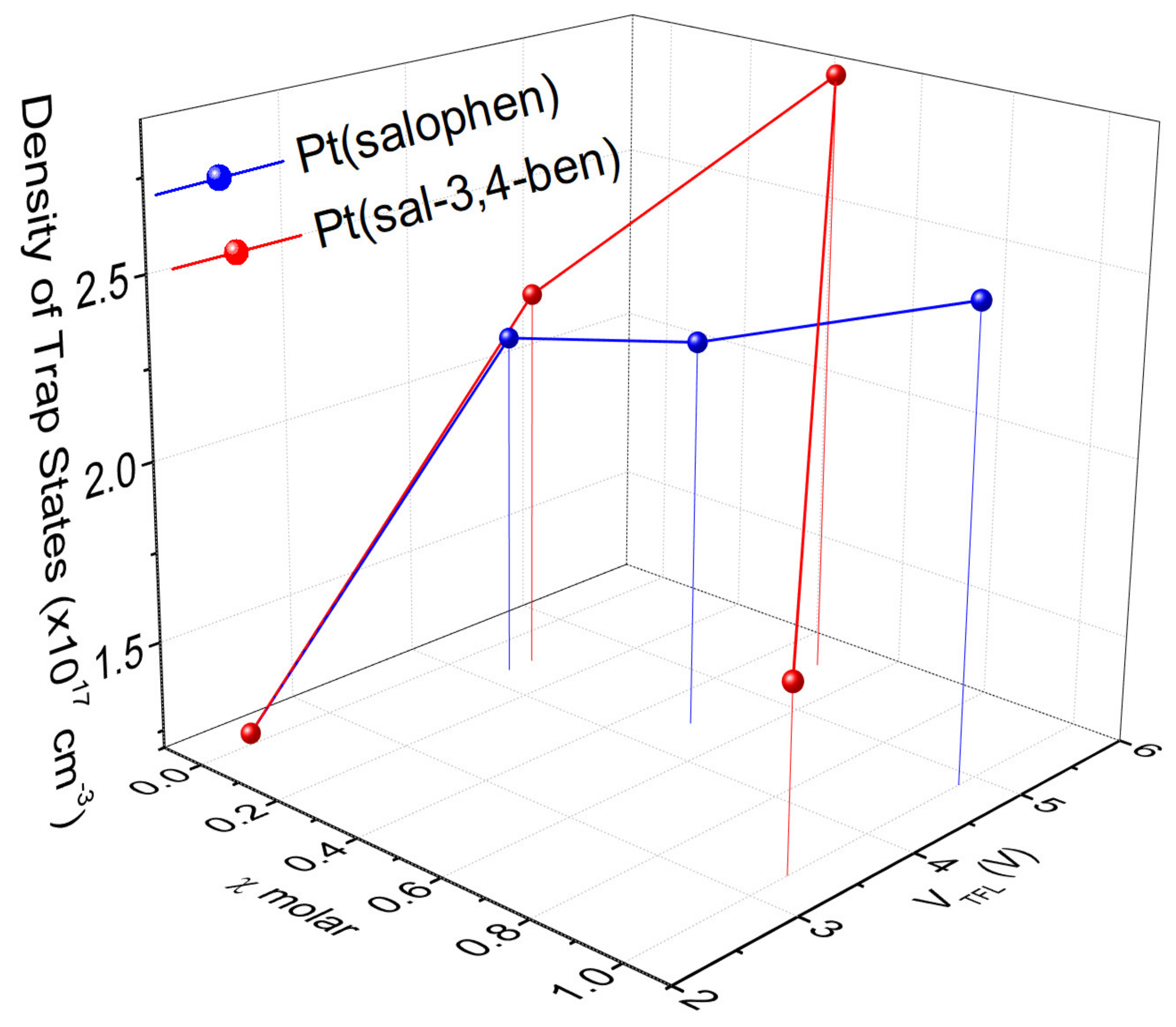
| % | λEL (nm) a | Von | μhSCLC (cm2 V−1 s−1) | μeSCLC (cm2 V−1 s−1) | Nt (cm−3) | μTCLC (cm2 V−1 s−1) | Et (meV) | Lmax (cd m−2) | ηcurr (cd A−1) | ηp (lm W−1) | EQEmax (%) | |
|---|---|---|---|---|---|---|---|---|---|---|---|---|
| PFO | 425 | 4.0 | 3.7 × 10⁻¹⁰ | 3.3 × 10⁻¹¹ | 1.23 × 10¹⁷ | 5.3 × 10⁻⁴ | 226.2 | 213 | 0.1 | 0.1 | 0.1 | |
| [Pt(salophen)] | 0.1 | 629 | 4.0 | 9.6 × 10⁻¹⁰ | 8.7 × 10⁻¹² | 2.17 × 10¹⁷ | 8.5 × 10⁻⁵ | 175.0 | 3103 | 2.8 | 1.8 | 2.2 |
| 0.5 | 629 | 4.4 | 2.4 × 10⁻¹⁰ | 5.8 × 10⁻¹¹ | 2.28 × 10¹⁷ | 1.4 × 10⁻⁵ | 262.8 | 2670 | 1.7 | 1.1 | 1.5 | |
| 1.0 | 620 | 7.5 | - | - | 2.51 × 10¹⁷ | 6.5 × 10⁻⁷ | 191.4 | 1214 | 0.2 | 0.6 | 0.2 | |
| [Pt(sal-3,4-ben)] | 0.1 | 643 | 3.2 | 4.7 × 10⁻⁵ | 5.4 × 10⁻¹⁰ | 2.27 × 10¹⁷ | 2.8 × 10⁻³ | 241.5 | 6224 | 12.1 | 11.9 | 15.3 |
| 0.5 | 639 | 5.8 | 1.5 × 10⁻⁹ | 7.4 × 10⁻¹⁰ | 2.90 × 10¹⁷ | 5.7 × 10⁻⁴ | 260.8 | 5227 | 0.9 | 0.2 | 1.0 | |
| 1.0 | 636 | 7.0 | - | - | 1.71 × 10¹⁷ | 2.8 × 10⁻⁶ | 236.1 | 1622 | 0.3 | 0.1 | 0.4 |
Publisher’s Note: MDPI stays neutral with regard to jurisdictional claims in published maps and institutional affiliations. |
© 2022 by the authors. Licensee MDPI, Basel, Switzerland. This article is an open access article distributed under the terms and conditions of the Creative Commons Attribution (CC BY) license (https://creativecommons.org/licenses/by/4.0/).
Share and Cite
Germino, J.C.; Duarte, L.G.T.A.; Mendes, R.A.; Faleiros, M.M.; de Morais, A.; de Freitas, J.N.; Pereira, L.; Atvars, T.D.Z. All-Solution Processed Single-Layer WOLEDs Using [Pt(salicylidenes)] as Guests in a PFO Matrix. Nanomaterials 2022, 12, 2497. https://doi.org/10.3390/nano12142497
Germino JC, Duarte LGTA, Mendes RA, Faleiros MM, de Morais A, de Freitas JN, Pereira L, Atvars TDZ. All-Solution Processed Single-Layer WOLEDs Using [Pt(salicylidenes)] as Guests in a PFO Matrix. Nanomaterials. 2022; 12(14):2497. https://doi.org/10.3390/nano12142497
Chicago/Turabian StyleGermino, José Carlos, Luís Gustavo Teixeira Alves Duarte, Rodrigo Araújo Mendes, Marcelo Meira Faleiros, Andreia de Morais, Jilian Nei de Freitas, Luiz Pereira, and Teresa Dib Zambon Atvars. 2022. "All-Solution Processed Single-Layer WOLEDs Using [Pt(salicylidenes)] as Guests in a PFO Matrix" Nanomaterials 12, no. 14: 2497. https://doi.org/10.3390/nano12142497