Article

First-Principles Study of Irn (n = 3–5) Clusters Adsorbed on Graphene and Hexagonal Boron Nitride: Structural and Magnetic Properties

1
School of Physics and Information Engineering, Shanxi Normal University, Taiyuan 030031, China
2
Key Laboratory of Spectral Measurement and Analysis of Shanxi Province, Shanxi Normal University, Taiyuan 030031, China
3
Key Laboratory of Materials Modification by Laser, Electron, and Ion Beams, Dalian University of Technology, Ministry of Education, Dalian 116024, China
*
Author to whom correspondence should be addressed.
Nanomaterials 2022, 12(14), 2436; https://doi.org/10.3390/nano12142436
Submission received: 23 June 2022 / Revised: 14 July 2022 / Accepted: 14 July 2022 / Published: 16 July 2022
(This article belongs to the Special Issue First-Principles Investigations of Low-Dimensional Nanomaterials)

Abstract

:
Magnetic clusters have attracted great attention and interest due to their novel electronic properties, and they have potential applications in nanoscale information storage devices and spintronics. The interaction between magnetic clusters and substrates is still one of the challenging research focuses. Here, by using the density functional theory (DFT), we study the structural stability and magnetic properties of iridium clusters (Irn, n = 3–5) adsorbed on two-dimensional (2D) substrates, such as graphene and hexagonal boron nitride (hBN). We find that the most favorable configurations of free Irn clusters change when adsorbed on 2D substrates. In the meantime, the magnetic moments of the most stable Irn reduce to 53% (graphene) and 23.6% (hBN) compared with those of the free−standing ones. Interestingly, about 12-times enlargement on the magnetic anisotropy energy can be found on hBN substrates. These theoretical results indicate that the cluster–substrate interaction has vital effects on the properties of Irn clusters.

Graphical Abstract

1. Introduction

Owing to unexpected electronic and magnetic properties, atomic clusters are promising candidates for technological applications such as catalysis and magnetic storage. They have been becoming gradually more and more attractive in interdisciplinary fields since the 1990s [1,2,3]. The size and atomic structure-dependent properties of clusters present a huge opportunity for designing cluster-assembled materials and devices. Therefore, determining the ground state structure of a cluster directly by combining experimental and theoretical techniques is vital [1,4].
Magnetic clusters have attracted special attention, especially those composed of transition metals (TM) [5]. Because of the strong spin–orbital coupling (SOC), it is expected that nanostructures containing TM atoms will possess possibly greater magnetic anisotropy energy (MAE), which is a key parameter in nano-information storage devices. Generally, with the increase in the atom number n, the geometric structure of clusters will undergo a transition from line models (n = 2–3) to planar models (n = 3–5) and then to three-dimensional configurations (such as a pyramid, octahedron, icosahedron, cube or core-shell model) [6,7,8,9,10,11,12,13]. For instance, owing to the s(p)-d hybrid, there is a predominantly icosahedral growth for Fe13 and Pd13 clusters [14,15]. The electronic and magnetic properties of magnetic clusters highly depend on the atomic size. As the cluster size increases, an odd–even oscillation of vertical ionization potentials occurs in Irn (n < 8) and Rhn (n < 13) clusters [16,17]. The strongly quenched orbital magnetic moment in size-dependent Fen (n = 3-20) clusters is obtained experimentally [14] and then confirmed by DFT calculations [18]. Furthermore, the size effects on magnetic moments have also been observed in Nin (n = 10–15) [19,20], Rhn (n = 2–13) [3,16], Pdn (n = 2–23, 55, 147) [15], Ptn (n = 2–20) [21] and Irn (n = 1–13) clusters [22].
Generally, clusters can be experimentally prepared by several methods, such as magnetron sputtering [23], laser vaporization [24,25,26] and chemical vapor deposition (CVD) [27]. Normally, a substrate is necessary for many applications of the clusters. The interaction between the cluster and substrate can affect both the geometric structure and physical properties of a cluster. For instance, under the influence of the cluster–substrate interaction, Fen (n = 2–7), (Mnn (n = 2–7) and Sin (n = 2–6, 10)) clusters on graphene prefer different growth modes and various orientations [28,29]. Additionally, the electronic and magnetic properties of the substrate can be effectively modulated by the adsorption of clusters [30,31,32,33]. When the Mn5 cluster is absorbed on graphene, the magnetic moment of the Mn5 cluster is enhanced by 186% because of the electron redistribution [29]. On the contrary, for Fen (n = 1, 4–6) clusters, the magnetic moment is reduced by 2–4 μB [28]. Furthermore, magnetic clusters can turn into stable nonmagnetic clusters when adsorbed on 2D substrates [33]. Interestingly, a large MAE can be achieved by absorbing clusters on substrates. Among them, Irn is a suitable candidate for nano-information storage devices and has been investigated extensively. Hu et al. [34] put an Ir2 dimer on the double vacancy site of 2D hexagonal boron nitride (hBN) and obtained an enlargement in MAE (~126 meV) [35]. Meanwhile, we have also investigated the substrate effect on MAE of Ir2 and found that MAE depends on the adsorption site and density [36]. However, from our limited knowledge, the interactions between magnetic clusters and substrates are still far from well known, especially on the MAE of larger clusters.
In this paper, by using first-principles calculations, we systematically study the interactions between Irn (n = 3–5) clusters and 2D substrates (graphene, hBN and germanene) [37]. Different ground state geometric structures of Irn and absorption sites of substrates are considered. We first investigate the geometric structures and stabilities with the help of cohesive and detachment energies. Then, we discuss the magnetic properties, including the magnetic moments and MAE, and explore the physics picture with the help of the local density of states and perturbation theory analysis. The present theoretical studies will provide insight into the substrate effect on larger magnetic clusters.

2. Materials and Methods

The structural, magnetic and electronic properties of Irn (n = 3–5) clusters adsorbed on 2D materials were studied by first-principles calculations, as implemented in the Vienna Ab-initio Simulation Package (VASP) code [38]. The ion–electron interaction was treated with the projector-augmented plane wave (PAW) potentials [39], and the exchange-correlation potential was described by generalized gradient approximation (GGA) with the Perdew–Burke–Ernzerhof (PBE) functional [40]. The wave functions were expanded in a plane wave basis set with an energy cut-off of 500 eV. The 2D substrates were chosen as 7 × 7 graphene, 7 × 7 hBN and 4 × 4 germanene supercells, respectively. To avoid the interaction between two neighboring layers, a vacuum space of 40 Å was added along the Z-direction. A k-mesh of 3 × 3 × 1 was used for the Brillouin zone. The atomic structures were fully relaxed without any symmetric constraints, with total energy and force convergence criteria of 10−4 eV and 0.01 eV/Å, respectively. For the calculations of the magnetic and electronic properties, the convergence criterion for the total energy was set to 10−6 eV, and the SOC effects were considered.
We employed binding energy (Eb, eV), cohesive energy (Ecoh, eV/atom) and detachment energy (Edet, eV) to determine the most energetically favorable configuration of Irn/2D. Eb can be used to evaluate the interaction between the Irn cluster and the 2D substrate, which is defined as:
Eb = EIrn + E2DEIrn/2D
where EIrn, E2D and EIrn/2D are the total energies of the free−standing Irn cluster, 2D substrate (graphene or hBN) and Irn/2D hybrid system, respectively. A larger Eb means a stronger interaction between Irn and the 2D materials. Ecoh is the energy gain when isolated Ir atoms are assembled into the Irn cluster, which is defined as:
Ecoh = (n × EIrEIrn)/n or Ecoh = (E2D + n × EIrEIrn/2D)/n
Here, n is the number of Ir atoms of the Irn cluster, EIr is the energy of an isolated Ir atom, EIrn is the total energy of the free−standing Irn cluster and E2D is the total energy of the 2D substrate, respectively. Edet is the energy gain when the Irn−1 cluster is transformed to Irn by adding one more Ir atom, which can be used to determine the most favorable cluster size n. For the free−standing cluster Irn or that on the 2D substrate, the detachment energy can be defined as:
Edet = EIrn−1 + EIrEIrn or Edet = EIrn−1/2D + EIr/2DEIrn/2DE2D
where EIrn−1/2D and EIr/2D are the total energies of the Irn−1/2D and Ir/2D hybrid systems, respectively.

3. Results

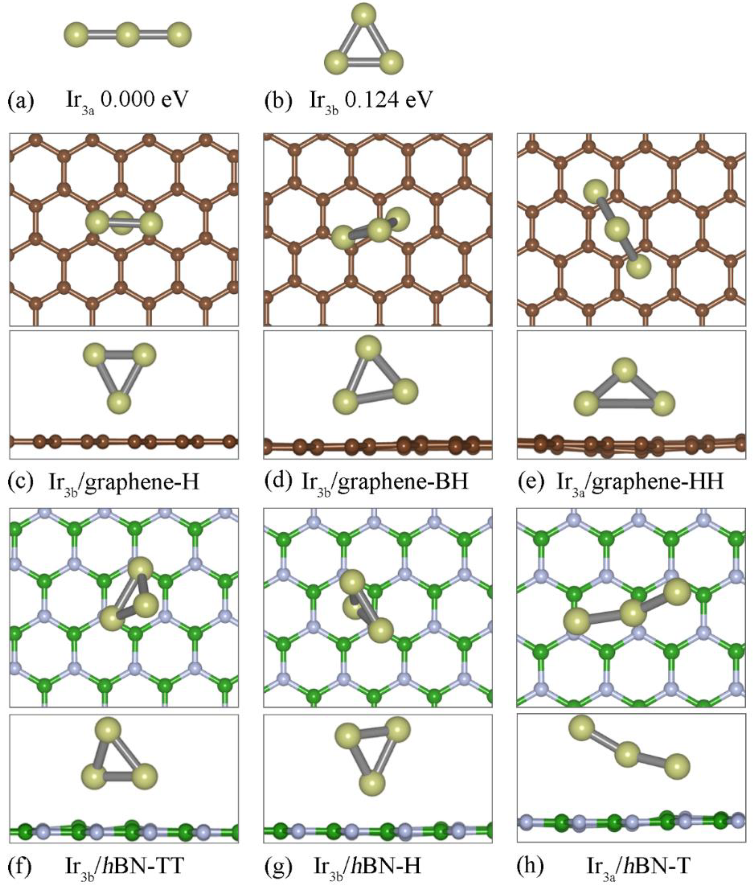
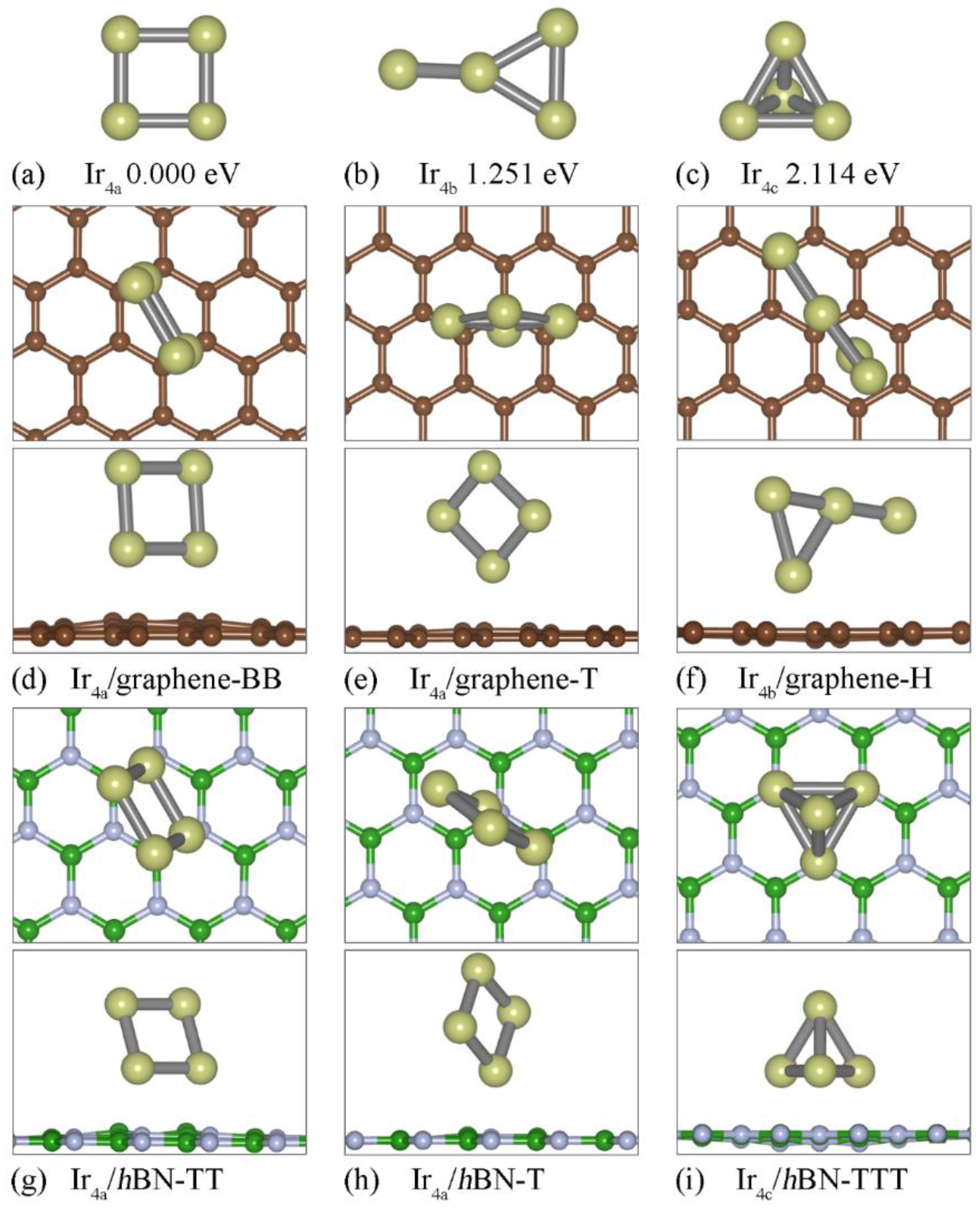
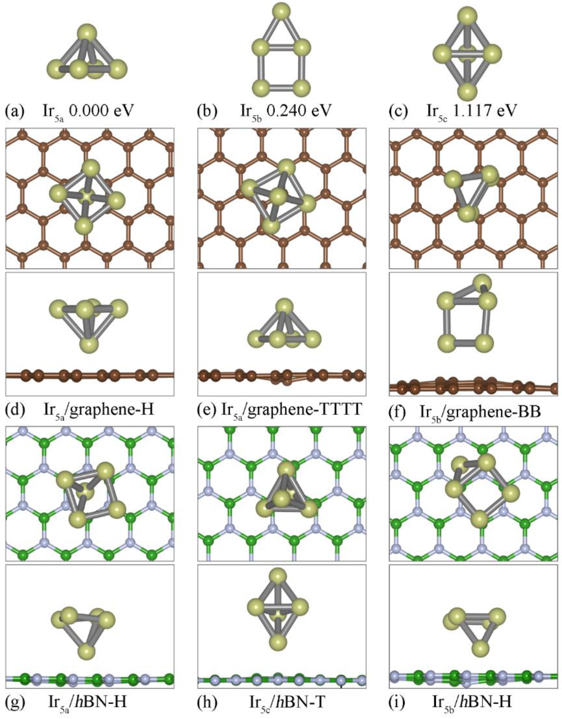
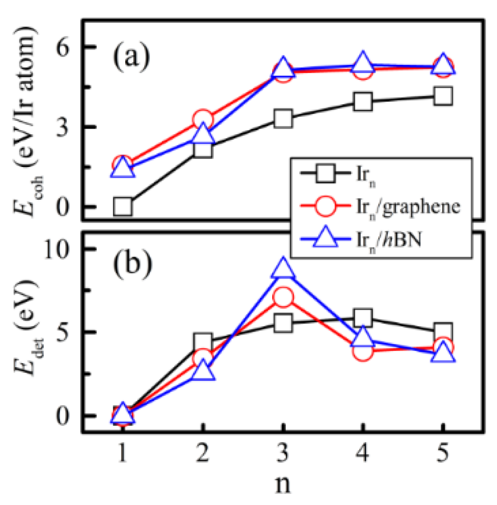
3.1. Structural Properties

We investigated the structural, electronic and magnetic properties of the magnetic Irn clusters on different 2D substrates and then compared them with the free−standing ones. For the Irn (n = 3, 4, 5) clusters, we considered different isomers corresponding to the most stable configuration and the metastable ones. We then put the Irn cluster above three kinds of substates: graphene, hBN and germanene, respectively. Owing to the stronger interaction between the Ir and Ge atoms, the Irn cluster will dissociate and embed into the monolayer germanene, which can induce defected germanene. Taking Ir3 clusters as the examples, we show the optimized configurations of Ir3 adsorbed on germanene (see Supplementary Figure S1). Therefore, differently from our previous work in which the favorite adsorption site for the Ir2 cluster was the single vacancy of germanene [36], we mainly discussed the graphene and hBN substrates. Three kinds of absorption sites have been considered: on the top of an atom (T), on the top of a C-C (B-N) bond (B) and on the top of a hexagonal-ring-center (H). Accordingly, the Irn cluster absorbed on the 2D substrate is named Irnm/2D-T (or B, H; see Figure 1), where n = 3, 4, 5 is the number of Ir atoms, m = a, b, c labels different isomers of free−standing Irn clusters, 2D is either graphene or hBN and T (or B, H) labels the absorption site of the nearest Ir atom.
As shown in Figure 1a,b, there are two relative stable configurations for the free−standing Ir3 cluster: the line model (Ir3a) and the triangle model (Ir3b). Hereafter, we set the energy of the most stable configuration as zero and ΔE as the energy difference between the most stable and metastable configuration, as listed in Table 1. Ir3a is more stable than Ir3b, with an energy difference of 0.124 eV. Ir3a has an average bond length of 2.181 Å. These results are consistent with most previous PBE calculations [22,41] and PW91 calculations [33]. However, when absorbed on graphene or the hBN substrate, the Ir3 cluster prefers the triangle model because of the substrate effect (see Figure 1c–h), which is similar to the Si3 cluster absorbed on the graphene substrate [42]. ΔE is 0.159 eV (on graphene) and 0.268 eV (on hBN), respectively. For the graphene substrate, the most stable configuration is the Ir3b/graphene-H (Figure 1c) hybrid system, in which the Ir3 plane is perpendicular to the graphene sheet, the innermost Ir atom is located at the H site with a d (distance between the Ir atom and the substrate) of 1.771 Å and the other two Ir atoms are located at the B site. As opposed to Ir3b/graphene-H, the most stable configuration is Ir3b/hBN-TT (Figure 1f), in which the plane of the Ir3 cluster has a tilt angle of 76.5° with a horizontal hBN sheet. Compared with Ir3b/graphene-H, there is an inversion for the triangle model, in which two nearer absorbed Ir atoms form chemical bonds with N atoms with a d of 2.248 Å. Owing to two Ir-N bonds, Ir3b/hBN-TT has an Eb of 5.583 eV, which is higher than that of Ir3a/graphene-H (5.352 eV).
Figure 2 shows three kinds of relative stable Ir4 configurations for the free−standing clusters, and those absorbed onto the graphene and hBN substrates, respectively. For the free−standing Ir4 clusters, the square planar (Ir4a, Figure 2a) is the most favorable configuration and has an average bond length of 2.338 Å. The most stable configuration and structure parameters are consistent with those in the previous report [22]. Unlike the Ir3 cluster, the most stable configurations of Ir4a remain unchanged on both the graphene and hBN substrate, along with a slight band angle deformation when they are adsorbed onto hBN. Figure 2e, h indicate that the metastable Ir4 on either the graphene or hBN is still a square planar configuration. The difference is that that are two Ir atoms bonded with the substrate in the most stable configuration, but there is only one in the metastable structure. Therefore, ΔE decreases from 1.251 eV (free−standing Ir4b) to 0.411 (Ir4a/hBN-T) and 0.093 eV (Ir4a/graphene-T), respectively. Similar to Ir3b/hBN-TT, for Ir4a/hBN-TT (Figure 2g), the Ir4a cluster plane has a tilt angle of 75.1° with the hBN sheet because of the strong Ir-N interactions. As shown in Table 1, Ir4/hBN has a higher Eb compared with Ir4/graphene, which indicates a stronger interaction between the cluster and the substrate. Note that, because the configuration of the Irn cluster in Irn-2D may be different, a higher Eb indicates a stronger interaction between the cluster and the substrate and does not guarantee a higher stability. For example, as listed in Table 1, Ir4c/hBN-TTT (Figure 2i) has a larger Eb, along with a higher total energy.
The free−standing Ir5 isomers are listed in Figure 3a–c, in which Ir5a (square pyramid model) is the most stable configuration, and the metastable ones are Ir5b (square adding a co-plane triangle model, with an ΔE of 0.24 eV) and Ir5c (triangular bipyramid model, with an ΔE of 1.117 eV), respectively. When it is absorbed on the 2D substrates, the square pyramid Ir5a is still the most stable. A previous theoretical calculation also suggested that the square pyramid model of Ir5 is more stable for both free−standing clusters [22,33,41] or on the monolayer graphene [43]. As shown in Figure 3d,g, the bottommost Ir atom of the cluster is located at the H site of the graphene (hBN) with a d of 1.989 (1.736) Å. Ir5c/hBN-T is metastable owing to its higher Eb (6.567 eV), which is larger than that of Ir5b/hBN-H (5.622 eV).
We employ Ecoh and Edet to further discuss the favorable Irn clusters on the substrates. As shown in Figure 4a, Ecoh increases with the number of cluster atoms (n) for both the free−standing Irn [33] and Irn/2D hybrid systems. Compared with the free−standing Irn cluster, Irn/2D possesses a higher Ecoh, suggesting that the substrate effect can make the Irn cluster energetically stable. The Ecoh of Ir5 on graphene (hBN) is 5.19 (5.34) eV/atom, which is comparable with that from Ghazi’s works [43,44]. As plotted in Figure 4b, for free−standing clusters, that the maximum of Edet belongs to the Ir4 configuration indicates that Ir4 is the favorite Irn cluster. After being absorbed on the substrates (either graphene or hBN), Ir3/2D turns out to be the most stable configuration due to it having the largest Edet.

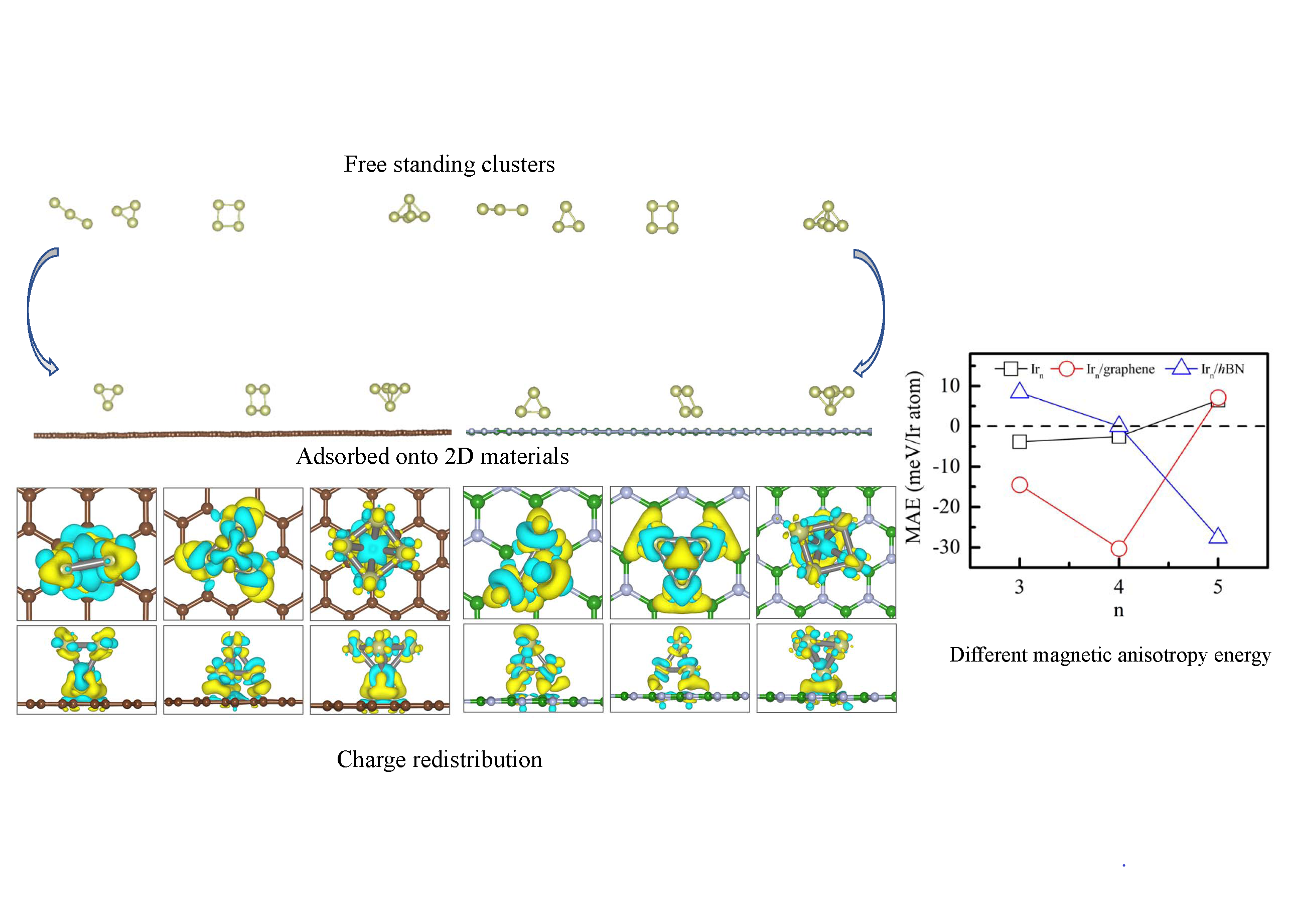
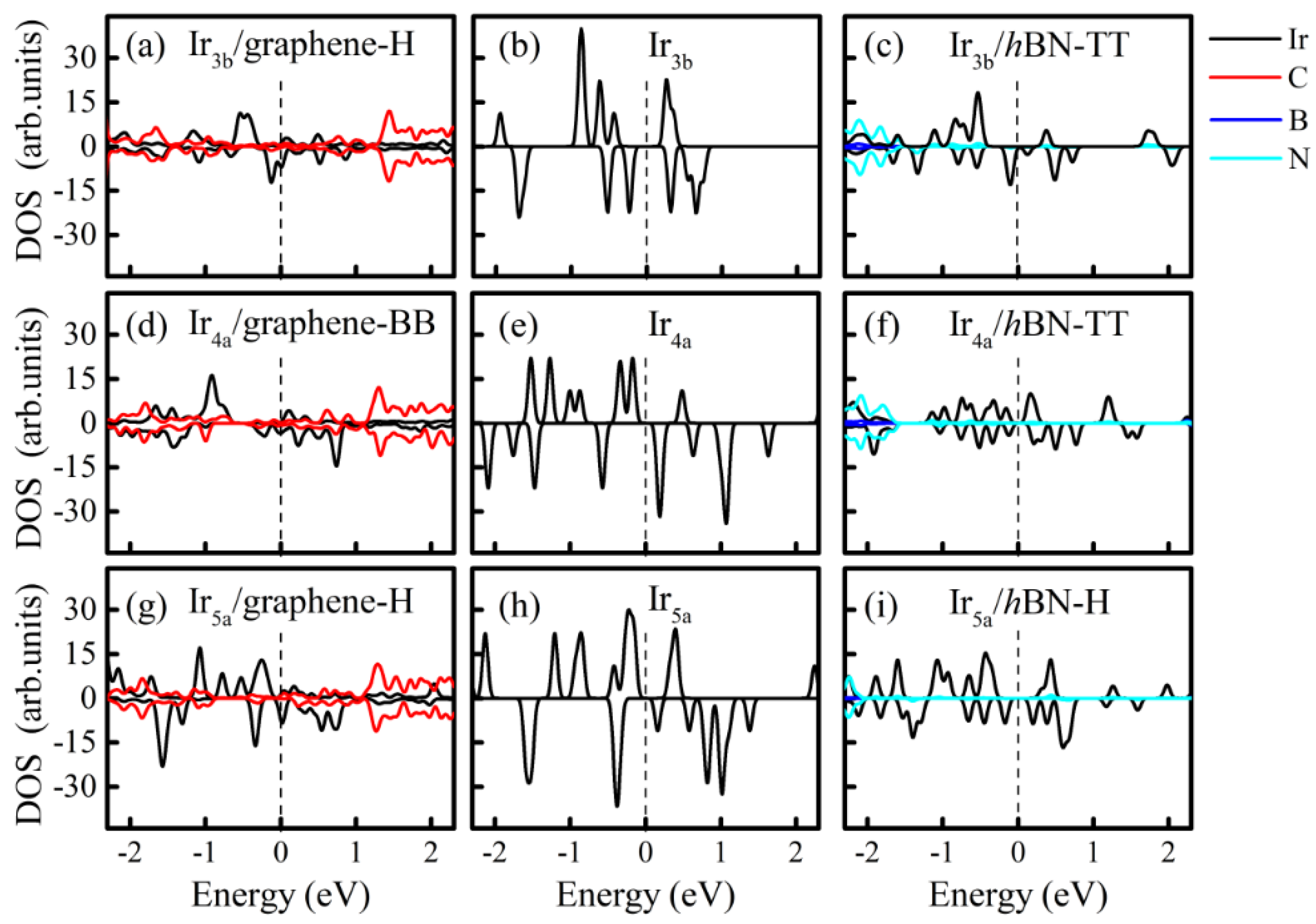
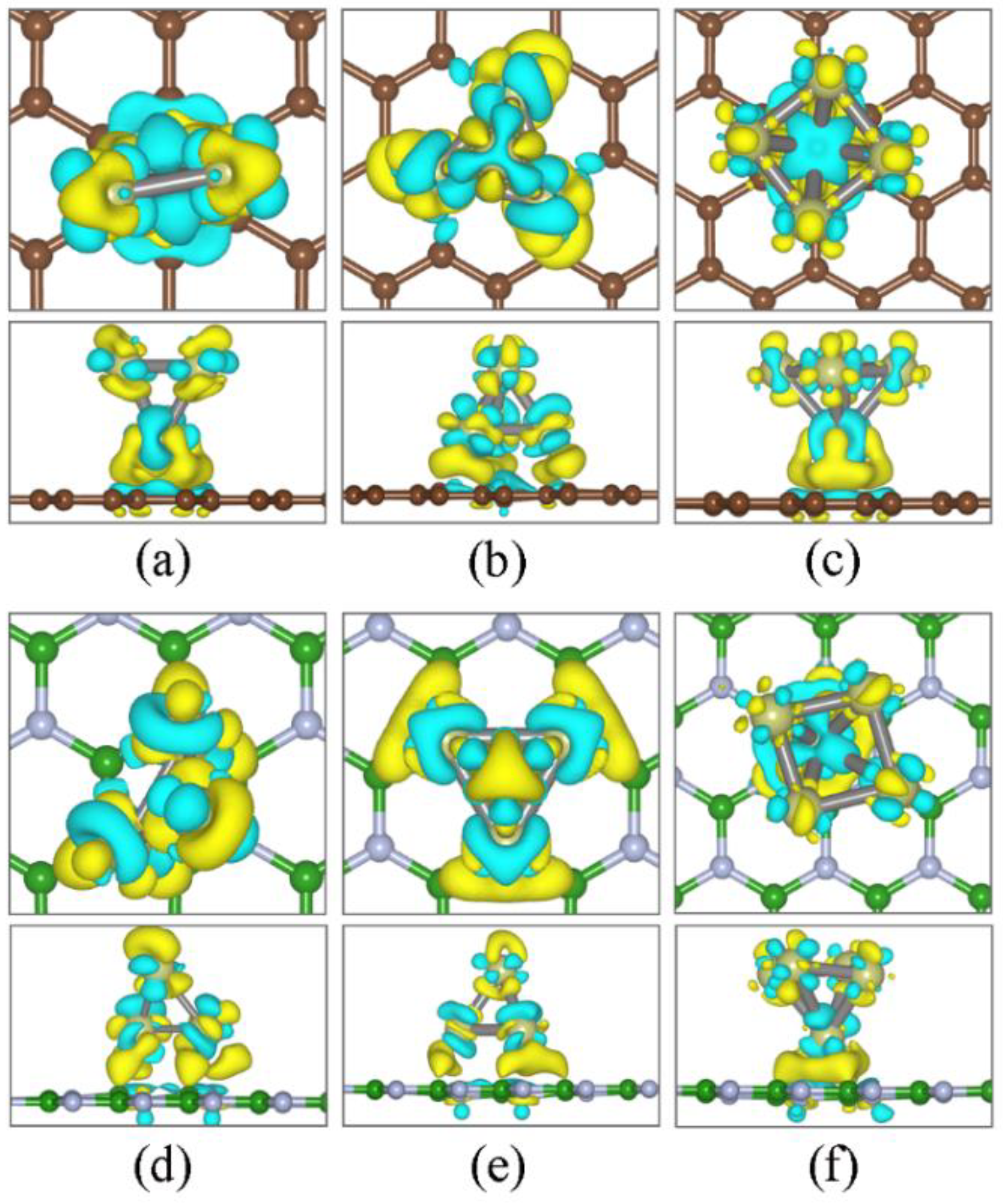
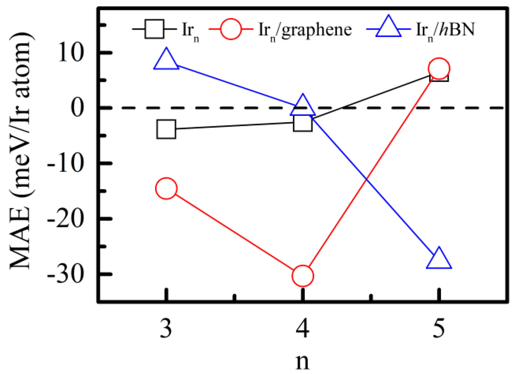
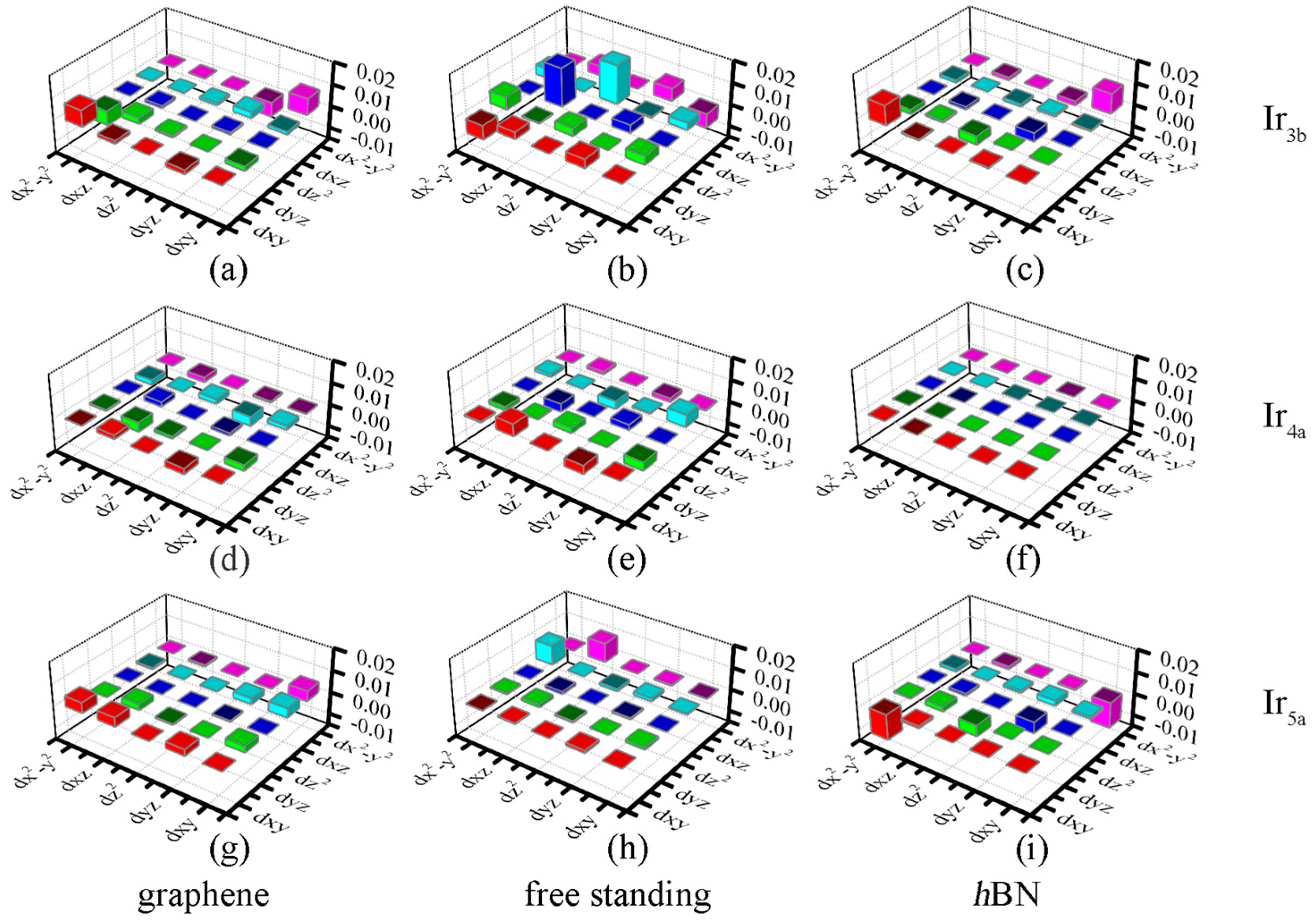
3.2. Magnetic Properties

We next discuss the magnetic properties of Irn clusters on graphene and hBN. By setting different spin directions in Irn, we can determine what the magnetic ground state (ferromagnetic or anti-ferromagnetic) is. For all the stable configurations, including the free−standing Irn and Irn on the substrates, the ferromagnetic ground state is more energetically favorable, as shown in Supplementary Table S1. The total magnetic moments of the free−standing Ir3a and Ir3b are 0.947 μB and 2.654 μB, respectively. The total magnetic moments of Ir4a, Ir4b and Ir4c are 6.509 μB, 3.583 μB and 0 μB, respectively. These results are consistent with the previous calculations [22,33]. Moreover, the total magnetic moments of Ir5a, Ir5b and Ir5c change to be 5.574 μB, 7.641 μB and 7.562 μB, respectively. As listed in Table 1, except for Ir3a/graphene-HH and Ir3b/hBN-TT, the magnetic moments of the Irn clusters on the 2D substrates decrease more or less. Compared with the free−standing Irn cluster, the magnetic moments of the most stable Irn clusters adsorbed onto the substrates were reduced to 53% (Ir3b/graphene-H) and 23.6% (Ir4a/hBN-TT), respectively. Furthermore, for metastable Ir4b/graphene-H, the magnetic moment of the Ir4b cluster is only 0.548 μB (84.7% reduction). The variation of the magnetic moment caused by the substrate effect or adsorption site can be understood by the charge transfer between the cluster and the 2D sheet.
Table 1 lists the charge transfer (d) between Irn and the substrates from the Bader analysis [45]. Interface bonds may form between the Irn cluster and the substrate due to the electron transferring. Firstly, the magnitude of d on graphene is generally larger than that on hBN and relies on the absorption site. Secondly, for the considered Irn/graphene, electrons transfer from the Irn cluster to the graphene sheet, corresponding to a negative d. On the contrary, the transfer direction depends on the bonded atom number when the clusters are absorbed onto the hBN substrate. Specifically, if one Ir atom is attached to the substrate, such as in Ir3b/hBN-H (as shown in Figure 1), the charges transfer from hBN to Irn (d > 0). If two or more atoms are attached to the substrate, such as in Ir3b/hBN-TT, the transfer direction is reversed (d < 0).
The density of states (DOS) of the most stable free−standing Irn and Irn/2D hybrid systems is shown in Figure 5. Generally speaking, the DOS of the Irn cluster is perturbed due to the substrate effect. The substrate effect can be divided into two parts: energy level repulsion and charge transfer. From the DFT calculations, the projected DOS indicated that dxz states are induced from the energy level repulsion between the dz2 states of Irn and the pz of C (N) atoms. Meanwhile, the energy level repulsion shifts the states and increases or decreases the magnetic moments of Irn. Taking Ir3 as an example, the magnetic moment of Ir3b (2.654 mB) is increased to 2.687 μB on hBN but decreased to 1.408 μB on graphene. Similar changes can also be found for the Ir4 and Ir5 clusters (see Table 1). The charge transfer can be quantitatively characterized by the Bader analysis (Table 1) and qualitatively characterized by the Charge Density Difference (CDD). The CDD in Figure 6 demonstrates that charge redistribution takes place at both the interface region and the Irn cluster. Note that, differently from other Irn/2D hybrid systems, the electrons in the Ir5a/hBN-H structure transfer from hBN to Ir atoms, as listed in Table 1. Accordingly, positive charge density dominates the interface region in Figure 6f.
Finally, we discuss the substrate effect on the magnetic anisotropy energy (MAE) of the Irn clusters. MAE is defined as the energy difference between different easy axes (parallel (//) and perpendicular (⊥) to the 2D substrate) per Ir atom, i.e., MAE (in meV/Ir atom) = E// − E. The MAE values of the free−standing Ir3b, Ir4a and Ir5a are 11.57, 10.05 and 32.43 meV, respectively, which are consistent with previous theoretical calculations [22]. However, owing to the slight structural difference, the MAE of the free−standing Ir4b (9.32 meV) is lower than that yielded from Ge’s calculation (40.26 meV) [41]. Figure 7 plots the MAE of the free−standing Irn clusters, Irn/graphene and Irn/hBN. Clearly, with the increase in n (from 3 to 5), the Irn clusters experience an easy-axis direction change. More importantly, under the influence of the substrate effect, the MAE is enlarged by about 4 times for the Ir3b/graphene and by 12 times for the Ir4a/graphene.
MAE can be understood with the help of the second-order perturbation approach [46], which is defined as:
MAE = ξ 2 U , O | < O | l z | U > | 2 | < O | l x | U > | 2 E U E O
where ξ is the SOC constant, O (U) stands for the occupied (unoccupied) states, EO (EU) stands for the corresponding energy eigenvalues and lz (lx) is the orbital angular momentum operator. As described by Equation (4), the coupling spin orbital matrix element difference, i.e., |<O|lz|U>|2 − |<O|lx|U>|2, contributes to the value of MAE, including different coupling orbitals and various coupling factors. Figure 8 shows the d orbital-resolved MAE of the free−standing Irn cluster and Irn/graphene (Irn/hBN). As shown in Figure 8b, the main contribution of the free−standing Ir3b cluster to the MAE comes from the matrix element difference between the dxz and dz2 orbitals. However, Figure 8a,c indicate that the main contributions on the substrate changed to dxy and dx2−y2 orbitals for both the hBN and graphene, owing to the dz2-to-dxy orbitals transition, as discussed above. For Ir4a, Figure 8e (free−standing) and Figure 8f (Ir4a/hBN) suggested that the interaction between dxz and dxy is the main contribution for MAE, which results in a smaller MAE. In Ir4a/graphene, we found that the d orbital is closer to the Fermi level, resulting in a higher MAE. Finally, the interactions between dx2−y2 and dxz (dxy) determine the MAEs of the free−standing (on substrates) Ir5a clusters. The positive (negative) contributions given by the matrix element difference between different orbitals and coupling factors result in different MAE values, as discussed in reference [46].

4. Conclusions

In conclusion, the structural and magnetic properties of Irn (n = 3–5) clusters adsorbed on 2D substrates (graphene and hBN) were systematically investigated using the DFT method. The calculated results show that, after the structure relaxation, the stability order of Irn may change on 2D substrates. The detachment energies suggest that, for the free−standing Irn, the most favorite cluster is the one of n = 3. After being absorbed on 2D substrates, the most stable cluster changes to n = 4. The magnetic moments of Irn generally decrease owing to the charge transfer between the Irn and the substrates, which depends on the substrate type and adsorption site. The MAE of the Irn cluster can be enlarged by 12 times for Ir4a/graphene, which is understood with the help of the second-order perturbation approach.

Supplementary Materials

The following supporting information can be downloaded at: https://www.mdpi.com/article/10.3390/nano12142436/s1, Figure S1: Three optimized configurations of Ir3 on Germanene; Table S1: The relative energies (in meV) of ferromagnetic (FM) and anti-ferromagnetic (AFM) states for the free−standing Irn and Irn on graphene and hBN substrates. We set the energy of FM (EFM) state as zero.

Author Contributions

M.G. (Mei Ge): conceptualization, writing—review and editing, funding acquisition; L.C.: writing—original draft preparation; M.G. (Miaomiao Guo): designing and performing the DFT calculations; Y.S.: resources; J.Z.: conceptualization, project administration, funding acquisition. All authors have read and agreed to the published version of the manuscript.

Funding

This research was funded by the National Natural Science Foundation of China, grant number 12074235; the Natural Science Foundation of Shanxi Province, grant number 202103021223252; and the Project for Graduate Research Innovation of Shanxi Normal University of China, grant number 2019XSY020.

Institutional Review Board Statement

Not applicable.

Informed Consent Statement

Not applicable.

Data Availability Statement

Not applicable.

Conflicts of Interest

The authors declare no conflict of interest.

References

  1. Douglass, D.C.; Bucher, J.P.; Bloomfield, L.A. Magnetic studies of free nonferromagnetic clusters. Phys. Rev. B 1992, 45, 6341–6344. [Google Scholar] [CrossRef] [PubMed]
  2. Cox, A.J.; Louderback, J.G.; Bloomfield, L.A. Experimental observation of magnetism in rhodium clusters. Phys. Rev. Lett. 1993, 71, 923–926. [Google Scholar] [CrossRef] [PubMed]
  3. Cox, A.J.; Louderback, J.G.; Apsel, S.E.; Bloomfield, L.A. Magnetism in 4d-transition metal clusters. Phys. Rev. B 1994, 49, 12295–12298. [Google Scholar] [CrossRef] [PubMed]
  4. Knight, W.D.; Clemenger, K.; de Heer, W.A.; Saunders, W.A.; Chou, M.Y.; Cohen, M.L. Electronic Shell Structure and Abundances of Sodium Clusters. Phys. Rev. Lett. 1984, 52, 2141–2143. [Google Scholar] [CrossRef]
  5. Chaves, A.S.; Piotrowski, M.J.; Da Silva, J.L.F. Evolution of the structural, energetic, and electronic properties of the 3d, 4d, and 5d transition-metal clusters (30 TMn systems for n = 2–15): A density functional theory investigation. Phys. Chem. Chem. Phys. 2017, 19, 15484–15502. [Google Scholar] [CrossRef] [PubMed]
  6. Gaston, N.; Schwerdtfeger, P. From the van der Waals dimer to the solid state of mercury with relativisticab initioand density functional theory. Phys. Rev. B 2006, 74, 024105. [Google Scholar] [CrossRef]
  7. Song, W.; Lu, W.-C.; Wang, C.Z.; Ho, K.M. Magnetic and electronic properties of the nickel clusters Nin (n ≤ 30). Comput. Theor. Chem. 2011, 978, 41–46. [Google Scholar] [CrossRef]
  8. Ruiz-Díaz, P.; Ricardo-Chávez, J.L.; Dorantes-Dávila, J.; Pastor, G.M. Magnetism of small Cr clusters: Interplay between structure, magnetic order, and electron correlations. Phys. Rev. B 2010, 81, 224431. [Google Scholar] [CrossRef]
  9. Yuan, H.K.; Chen, H.; Ahmed, A.S.; Zhang, J.F. Density-functional study of Scn (n = 2–16) clusters: Lowest-energy structures, electronic structure, and magnetism. Phys. Rev. B 2006, 74, 144434. [Google Scholar] [CrossRef]
  10. Datta, S.; Kabir, M.; Saha-Dasgupta, T. Ab initio study of structural stability of small 3d late transition metal clusters: Interplay of magnetization and hybridization. Phys. Rev. B 2011, 84, 075429. [Google Scholar] [CrossRef]
  11. Du, J.; Sun, X.; Chen, J.; Jiang, G. A Theoretical Study on Small Iridium Clusters: Structural Evolution, Electronic and Magnetic Properties, and Reactivity Predictors. J. Phys. Chem. A 2010, 114, 12825–12833. [Google Scholar] [CrossRef] [PubMed]
  12. Guo, P.; Zheng, J.-M.; Zhao, P.; Zheng, L.-L.; Ren, Z.-Y. The relativistic density functional investigations on geometries, electronic and magnetic properties of Irn (n = 1–13) clusters. Chin. Phys. B 2010, 19, 083601. [Google Scholar]
  13. Ilgaz Aysan, I.; Gorkan, T.; Ozdemir, I.; Kadioglu, Y.; Gokoglu, G.; Akturk, E. Electronic structure, cohesive and magnetic properties of iridium oxide clusters adsorbed on graphene. J. Mol. Graph. Model. 2020, 101, 107726. [Google Scholar] [CrossRef]
  14. Niemeyer, M.; Hirsch, K.; Zamudio-Bayer, V.; Langenberg, A.; Vogel, M.; Kossick, M.; Ebrecht, C.; Egashira, K.; Terasaki, A.; Moller, T.; et al. Spin coupling and orbital angular momentum quenching in free iron clusters. Phys. Rev. Lett. 2012, 108, 057201. [Google Scholar] [CrossRef]
  15. Kumar, V.; Kawazoe, Y. Icosahedral growth, magnetic behavior, and adsorbate-induced metal-nonmetal transition in palladium clusters. Phys. Rev. B 2002, 66, 144413. [Google Scholar] [CrossRef]
  16. De Oliveira, A.Z.; Jorge, F.E. Structural, electronic, electrical, and magnetic properties of Rh (1 ≤ n ≤ 13) clusters. Comput. Theor. Chem. 2020, 1177, 112765. [Google Scholar] [CrossRef]
  17. Jorge, F.E.; da Costa Venâncio, J.R. Structure, stability, catalytic activity, and polarizabilities of small iridium clusters. Chin. Phys. B 2018, 27, 063102. [Google Scholar] [CrossRef]
  18. Yuan, H.K.; Chen, H.; Kuang, A.L.; Tian, C.L.; Wang, J.Z. The spin and orbital moment of Fe(n) (n = 2–20) clusters. J. Chem. Phys. 2013, 139, 034314. [Google Scholar] [CrossRef] [PubMed]
  19. Lee, H.W.; Chang, C.M.; Hsing, C.R. Puzzle of magnetic moments of Ni clusters revisited using quantum Monte Carlo method. J. Chem. Phys. 2017, 146, 084313. [Google Scholar] [CrossRef]
  20. Langenberg, A.; Hirsch, K.; Ławicki, A.; Zamudio-Bayer, V.; Niemeyer, M.; Chmiela, P.; Langbehn, B.; Terasaki, A.; Issendorff, B.V.; Lau, J.T. Spin and orbital magnetic moments of size-selected iron, cobalt, and nickel clusters. Phys. Rev. B 2014, 90, 184420. [Google Scholar] [CrossRef] [Green Version]
  21. Kumar, V.; Kawazoe, Y. Evolution of atomic and electronic structure of Pt clusters: Planar, layered, pyramidal, cage, cubic, and octahedral growth. Phys. Rev. B 2008, 77, 205418. [Google Scholar] [CrossRef]
  22. Liang, X.; Wu, X.; Huang, X.; Su, Y.; Hu, J.; Zhao, J. Magnetic Anisotropy of Small Irn Clusters (n = 2–5). J. Cluster. Sci. 2016, 27, 935–946. [Google Scholar] [CrossRef]
  23. Bernareggi, M.; Chiarello, G.L.; West, G.; Ratova, M.; Ferretti, A.M.; Kelly, P.; Selli, E. Cu and Pt clusters deposition on TiO2 powders by DC magnetron sputtering for photocatalytic hydrogen production. Catal. Today 2019, 326, 15–21. [Google Scholar] [CrossRef] [Green Version]
  24. Huang, X.; Lu, S.-J.; Liang, X.; Su, Y.; Sai, L.; Zhang, Z.-G.; Zhao, J.; Xu, H.-G.; Zheng, W. Structures and Electronic Properties of V3Sin– (n = 3–14) Clusters: A Combined Ab Initio and Experimental Study. J. Phys. Chem. C 2015, 119, 10987–10994. [Google Scholar] [CrossRef]
  25. Liang, X.-Q.; Deng, X.-J.; Lu, S.-J.; Huang, X.-M.; Zhao, J.-J.; Xu, H.-G.; Zheng, W.-J.; Zeng, X. Probing Structural, Electronic, and Magnetic Properties of Iron-Doped Semiconductor Clusters Fe2Gen−/0 (n = 3–12) via Joint Photoelectron Spectroscopy and Density Functional Study. J. Phys. Chem. C 2017, 121, 7037–7046. [Google Scholar] [CrossRef]
  26. Huang, X.; Xu, H.G.; Lu, S.; Su, Y.; King, R.B.; Zhao, J.; Zheng, W. Discovery of a silicon-based ferrimagnetic wheel structure in VxSi12 (x = 1–3) clusters: Photoelectron spectroscopy and density functional theory investigation. Nanoscale 2014, 6, 14617–14621. [Google Scholar] [CrossRef]
  27. Barker, B.A.; Bradley, A.J.; Ugeda, M.M.; Coh, S.; Zettl, A.; Crommie, M.F.; Louie, S.G.; Cohen, M.L. Geometry and electronic structure of iridium adsorbed on graphene. Phys. Rev. B 2019, 99, 075431. [Google Scholar] [CrossRef] [Green Version]
  28. Liu, X.; Wang, C.Z.; Lin, H.Q.; Hupalo, M.; Thiel, P.A.; Ho, K.M.; Tringides, M.C. Structures and magnetic properties of Fe clusters on graphene. Phys. Rev. B 2014, 90, 155444. [Google Scholar] [CrossRef]
  29. Liu, X.; Wang, C.-Z. Growth mode and structures of magnetic Mn clusters on graphene. RSC Adv. 2016, 6, 64595–64604. [Google Scholar] [CrossRef]
  30. Cui, H.; Jia, P. Doping effect of small Rhn (n = 1–4) clusters on the geometric and electronic behaviors of MoS2 monolayer: A first-principles study. Appl. Surf. Sci. 2020, 526, 146659. [Google Scholar] [CrossRef]
  31. Ju, W.; Li, T.; Su, X.; Li, H.; Li, X.; Ma, D. Au cluster adsorption on perfect and defective MoS2 monolayers: Structural and electronic properties. Phys. Chem. Chem. Phys. 2017, 19, 20735–20748. [Google Scholar] [CrossRef] [PubMed]
  32. Wang, Y.; Su, Y.; Kang, L. Stability and nucleation of Irn (n = 1–5) clusters on different γ-Al2O3 surfaces: A density functional theory study. Phys. Lett. A 2016, 380, 718–725. [Google Scholar] [CrossRef]
  33. Chen, Y.; Huo, M.; Chen, T.; Li, Q.; Sun, Z.; Song, L. The properties of Irn (n = 2–10) clusters and their nucleation on gamma-Al2O3 and MgO surfaces: From ab initio studies. Phys. Chem. Chem. Phys. 2015, 17, 1680–1687. [Google Scholar] [CrossRef] [PubMed]
  34. Li, J.; Wang, H.; Hu, J.; Wu, R.Q. Search for giant magnetic anisotropy in transition-metal dimers on defected hexagonal boron nitride sheet. J. Chem. Phys. 2016, 144, 204704. [Google Scholar] [CrossRef]
  35. Xu, M.; Liang, T.; Shi, M.; Chen, H. Graphene-like two-dimensional materials. Chem. Rev. 2013, 113, 3766–3798. [Google Scholar] [CrossRef]
  36. Guo, M.; Liang, X.; Wang, H.; Zhang, J. Magnetic anisotropy of iridium dimers on two-dimensional materials. Phys. Chem. Chem. Phys. 2020, 22, 238–244. [Google Scholar] [CrossRef]
  37. Cahangirov, S.; Topsakal, M.; Aktürk, E.; Şahin, H.; Ciraci, S. Two-and one-dimensional honeycomb structures of silicon and germanium. Phy. Rev. Lett. 2009, 102, 236804. [Google Scholar] [CrossRef] [Green Version]
  38. Kresse, G.; Furthmuller, J. Efficient iterative schemes for ab initio total-energy calculations using a plane-wave basis set. Phys. Rev. B 1996, 54, 11169. [Google Scholar] [CrossRef]
  39. Kresse, G.; Joubert, D. From ultrasoft pseudopotentials to the projector augmented-wave method. Phys. Rev. B 1999, 59, 1758–1775. [Google Scholar] [CrossRef]
  40. Perdew, J.P.; Burke, K.; Ernzerhof, M. Generalized Gradient Approximation Made Simple. Phys. Rev. Lett. 1996, 77, 3865. [Google Scholar] [CrossRef] [Green Version]
  41. Ge, G.-X.; Yan, H.-X.; Yang, J.-M.; Zhou, L.; Wan, J.-G.; Zhao, J.-J.; Wang, G.-H. Manipulation of magnetic anisotropy in Irn+1 clusters by Co atom. Phys. A 2016, 453, 194–202. [Google Scholar] [CrossRef]
  42. Yong, Y.; Hao, X.; Li, C.; Li, X.; Li, T.; Cui, H.; Lv, S. Density functional studies of small silicon clusters adsorbed on graphene. RSC Adv. 2015, 5, 38680–38689. [Google Scholar] [CrossRef]
  43. Ostad, F.Z.; Ghazi, M.E.; Javan, M.; Izadifard, M. DFT study of Ptn, Pdn, and Irn (n = 5, 6) clusters adsorbed on graphene: Structural and electronic properties. Phys. B 2019, 575, 411678. [Google Scholar] [CrossRef]
  44. Zargari, F.; Javan, M.; Ghazi, M.E.; Izadifard, M. Graphene-like boron nitride supported Irn, Pdn, and Ptn (n = 5, 6) clusters: A DFT study. Diam. Relat. Mater. 2020, 110, 108110. [Google Scholar] [CrossRef]
  45. Tang, W.; Sanville, E.; Henkelman, G. A grid-based Bader analysis algorithm without lattice bias. J. Phys. Condens. Matter 2009, 21, 084204. [Google Scholar] [CrossRef] [PubMed]
  46. Wang, D.S.; Wu, R.; Freeman, A.J. First-principles theory of surface magnetocrystalline anisotropy and the diatomic-pair model. Phys. Rev. B 1993, 47, 14932–14947. [Google Scholar] [CrossRef]
Figure 1. Atomic structures of the (a) Ir3a (line model) and (b) Ir3b (triangle model) clusters. Top and side view of the three relative stable atomic structures of the Ir3 cluster adsorbed on the graphene (ce) and hBN (fh) substrate, respectively. The Ir, C, B and N atoms are labeled with golden, brown, green and gray balls, respectively.
Nanomaterials 12 02436 g001
Figure 2. Atomic structures of the (a) Ir4a (square planar model), (b) Ir4b (a triangle configuration adding the fourth atom attached with the vertex of the triangle) and (c) Ir4c (tetrahedral model) clusters. Top and side view of the three relative stable atomic structures of the Ir4 cluster adsorbed on the graphene (df) and hBN (gi) substrate, respectively.
Nanomaterials 12 02436 g002
Figure 3. Atomic structures of the three relative stable atomic structures of the Ir5 clusters for the free−standing (ac), graphene ((df), top and side view) and hBN ((gi), top and side view) substrate, respectively.
Nanomaterials 12 02436 g003
Figure 4. Ecoh (a) and Edef (b) of the most stable structure for the Irn, Irn/graphene (hBN) clusters (n = 1–5).
Nanomaterials 12 02436 g004
Figure 5. DOS for free standing Irn clusters (b,e,h) and Irn/graphene (a,d,g) and Irn/hBN (c,f,i) hybrid systems. Contributions of Ir, C, B and N atoms are highlighted in black, red, blue and cyan, respectively.
Nanomaterials 12 02436 g005
Figure 6. CDD of the most stable structure of Ir3 to Ir5 adsorbed on graphene (ac) and hBN (df). Every figure shows the top and side views of CDD, respectively. Yellow and blue isosurfaces represent positive and negative charge densities. The isosurface is set at 0.005 e Å−3.
Nanomaterials 12 02436 g006
Figure 7. The MAE of the most stable free−standing Irn and Irn/2D systems (n = 3–5), respectively. The zero MAE is labeled by a dashed line.
Nanomaterials 12 02436 g007
Figure 8. The angular momentum operator matrix of the d orbital of the most stable structure: (a) Ir3b/graphene-H, (b) free−standing Ir3b, (c) Ir3b/hBN-TT, (d) Ir4a/graphene-BB, (e) free−standing Ir4a, (f) Ir4a/hBN-TT, (g) Ir5a/graphene-H, (h) free−standing Ir5a and (i) Ir5a/hBN-H. The units of the coordinates are eV.
Nanomaterials 12 02436 g008
Table 1. The energy difference between the most stable configuration and its isomer (ΔE, eV), the binding energy (Eb, eV), the minimum distance between the cluster and the substrate (d, Å), the magnetic moment of the clusters (μ, μB) and the hybrid system (μtot, μB) and the transferred charge from the cluster to the 2D substrate (δ, e). The negative δ represents the electrons transferring from the cluster to the 2D substrate.
ΔEEbdμμtotδ
Ir3b/graphene-H05.3521.7711.4081.287−0.163
Ir3b/graphene-BH0.1595.1922.0072.3852.517−0.221
Ir3a/graphene-HH0.2784.9501.7141.0171.083−0.269
Ir3b/hBN-TT05.5832.2482.6872.713−0.0305
Ir3b/hBN-H0.2685.3151.9572.6442.7020.101
Ir3a/hBN-T0.6914.7682.2530.8220.8290.107
Ir4a/graphene-BB04.8182.6624.9294.973−0.245
Ir4a/graphene-T0.0934.7252.0804.9434.941−0.104
Ir4b/graphene-H0.4625.6071.8950.5480.259−0.037
Ir4a/hBN-TT05.5462.3631.5351.519−0.023
Ir4a/hBN-T0.4115.1352.2412.8772.9000.010
Ir4c/hBN-TTT0.9386.7222.07500−0.133
Ir5a/graphene-H05.4341.9894.5164.539−0.173
Ir5a/graphene-TTTT0.5864.8472.3742.1812.196−0.468
Ir5b/graphene-BB0.6455.0292.5952.4522.452−0.170
Ir5a/hBN-H05.5541.7363.8613.8440.093
Ir5c/hBN-T0.1036.5672.2982.3772.3580
Ir5b/hBN-H0.1725.6221.7423.9403.9330.067
Publisher’s Note: MDPI stays neutral with regard to jurisdictional claims in published maps and institutional affiliations.

