1. Introduction
Electrical conductivities of metal or alloy films [
1,
2,
3] have been widely studied by many researchers. Conductivities of films are often weaker than those of metal or alloy bulks [
4,
5] due to the presence of numerous point, line and surface defects in films. Therefore, many researchers [
6,
7,
8] have done their utmost to improve film electrical conductivity for reducing the heat and energy loss generated by the working device to extend service life. The film devices with high electrical resistivity [
1,
2,
9] have been also utilized in unique applications such as electrical heating devices and resistors in heating and cooling equipment and high-resistivity resistors working in high-voltage and high-temperature circumstances. There are many methods or treatment processes to increase electrical resistivity, for instance, alloy films [
10,
11] were oxidized to increase electrical resistivity owing to the wide band gaps and few free electrons of metal or alloy oxides [
12,
13].
Previous studies have focused on the electrical property [
14,
15] of granular films, aiming to enhance the conductivity of alloy films, and these granular films with an anomalous Hall coefficient could be a desirable and potential candidate for Hall devices. Many vacancies and dislocations [
14] into metallic or alloyed films are present and seriously block electronic transport in these films to increase film electrical resistivity, which provides a feasible method to prepare high-resistivity films. A study about the local conductivity of lead zirconate titanate (PZT) films [
16] revealed the mechanisms of current percolation determined by traps in the films and at grain interfaces. In another study, Boff et al. [
17] showed that the electrical resistance of Co-Al
2O
3 granular films decreased with increasing volts in a low-field regime where granular films with a higher range of resistance variation were prepared. However, the preparation and treatment methods of the above granular films with high resistivity are complex.
In this work, based on previous studies about immiscible alloy films [
18,
19], the two immiscible metals of Ag and Co were sputtered and deposited on polyimide (PI) to prepare Ag-Co films under a stable magnetic field. The ratio of Ag and Co into granular films and film thicknesses would both affect film electrical resistivity, and hence the effects of Co content and film thicknesses on Ag-Co film conductivity were earnestly investigated. On the other hand, annealing temperature [
14,
15] is a crucial factor for the electrical resistivity variation of granular films; thus, we annealed these as-deposited Ag-Co films at different temperatures to examine the relationship between film resistivity and annealing temperatures. COMSOL Multiphysics software was employed to simulate the electron trajectory to explain and illustrate the critical influence of film surface morphology on film resistivity.
2. Materials and Methods
Ag-Co films were deposited on PI under a permanent magnetic field by sputtering a radio frequency composed target, which was made up of an Ag target (Φ 50 mm × 4 mm, 99.99% purity) and Co sheets (10 mm × 10 mm × 1 mm, 99.99% purity). After the background vacuum was down to 5 × 10⁻⁴ Pa, argon (Ar) was injected and the pressure and power of sputtering progression were set at 0.6 Pa and 100 W, respectively. Ag-Co films with different Co contents and film thicknesses were prepared by modifying the number of Co sheets and sputtering time at room temperature, respectively. Subsequently, the as-deposited Ag-Co films were annealed into a tube furnace, full of Ar, for 1 h. We used a blade to destroy the surface of the Ag-Co films and observed and measured the cross sections of the Ag-Co films. We calculated the average value of several times measured thicknesses and obtained the thickness of the Ag-Co films.
The sheet resistance of the Ag-Co films was measured by a four-probe resistance tester (RTS8, 4Probes Tech Ltd., Guangzhou, China) and the surface morphology of the Ag-Co films was observed by a field emission scanning electron microscope (FESEM, JSM-7800F, JEOL Ltd., Tokyo, Japan). In addition, the microstructure and composition of the Ag-Co films were obtained by high-resolution transmission electron microscopy (HRTEM, JEM-2100, JEOL Ltd., Tokyo, Japan) and energy-dispersive X-ray spectroscopy (EDS). The ion trajectory in the films was simulated by COMSOL Multiphysics software and the simulation with 1 μm × 1 μm × 0.2 μm was built in COMSOL Multiphysics software. Negative ions with 1 charge were injected to simulate the trajectory of electrons in the films.
3. Results and Discussion
3.1. Resistivity of Ag-Co Films with Different Thicknesses
The function of the sheet resistance (R
☐) and the resistivity (ρ) of the films is shown in Equation (1):
where d is the thickness of the Ag-Co films.
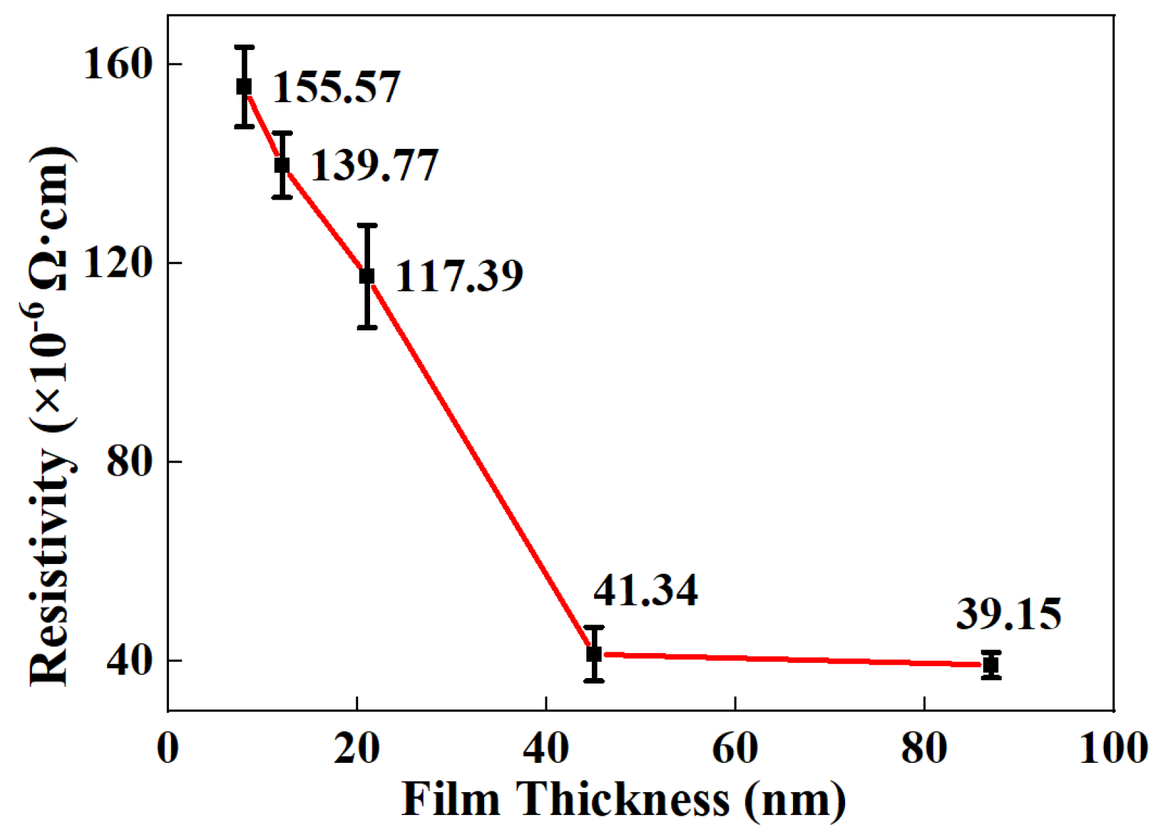
It can be observed from
Figure 1 that the resistivity of the Ag-Co films reduces from 155.57 × 10
−6 Ω cm to 39.15 × 10
−6 Ω cm as the film thicknesses increase from 8 nm to 87 nm, in good agreement with the variation trend between film thicknesses and the resistivity of Cr-Si-Ta-Al films [
2]. In another study about film thickness and crystallinity, C. Hsieh [
20] provided evidence that thick films could improve the crystallinity of PbPc films. In terms of another study about film materials and film thicknesses by molecular dynamics, T. Yamamoto [
21] further demonstrated that thick films present better crystallization than n-alkane ultrathin films. Thus, film resistivity reduces with the increase of Ag-Co film thickness due to better crystallization and fewer defects in Ag-Co films.
3.2. Resistivity of Ag-Co Films Annealed at Different Temperatures
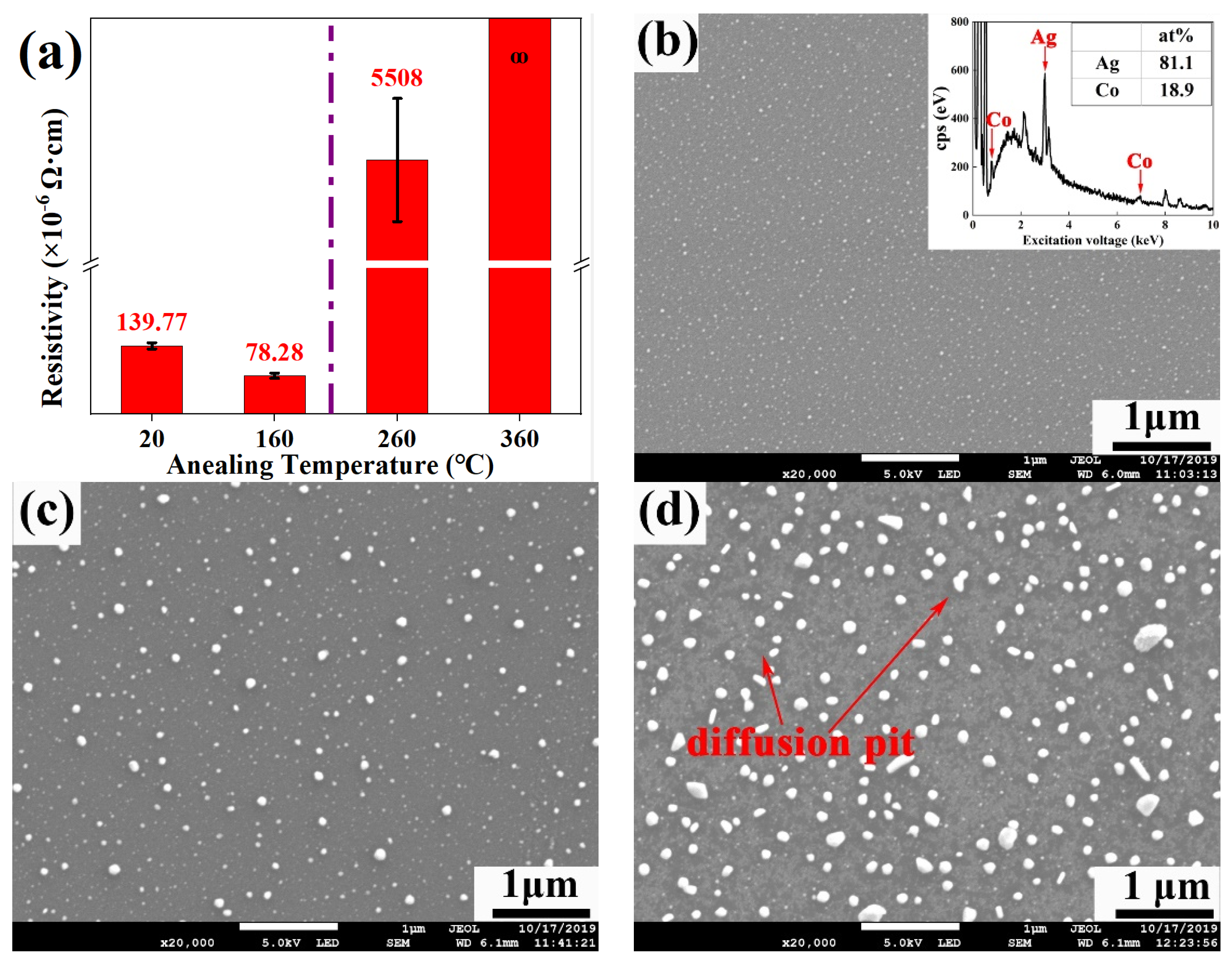
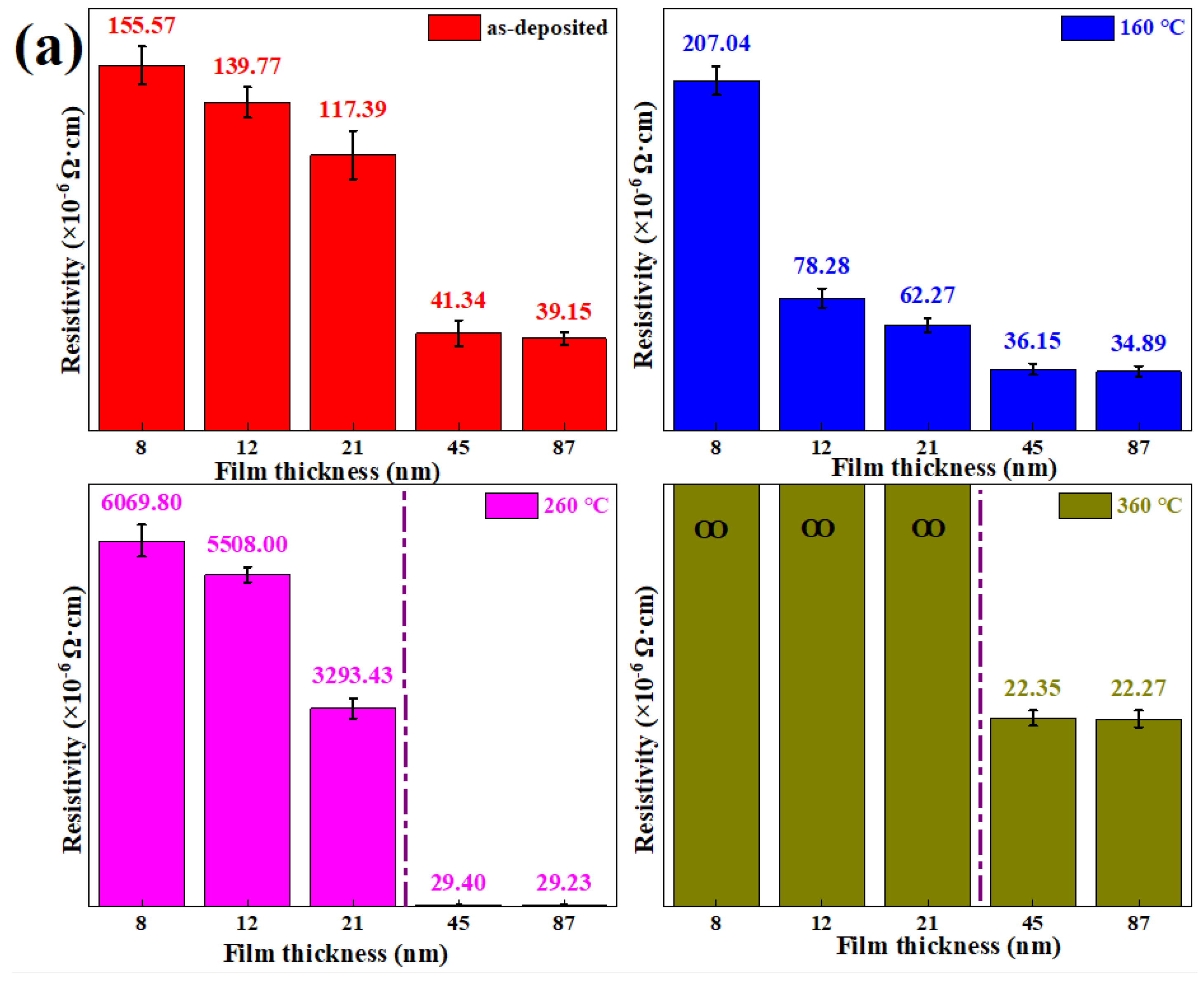
The relationship between the film resistivity and annealing temperature of Ag-Co films is shown in
Figure 2a. The Ag-Co films’ resistivity decreases by 44% with the increase of annealing temperatures from room temperature to 160 °C, in agreement with the results of Cr-Si-Ta-Al films [
2], which indicates that high-temperature annealing temperatures could decrease film resistivity ascribed to improving film crystallization. However, Ag-Co film resistivity sharply increases or even cannot be measured when annealing temperature is hotter than 260 °C.
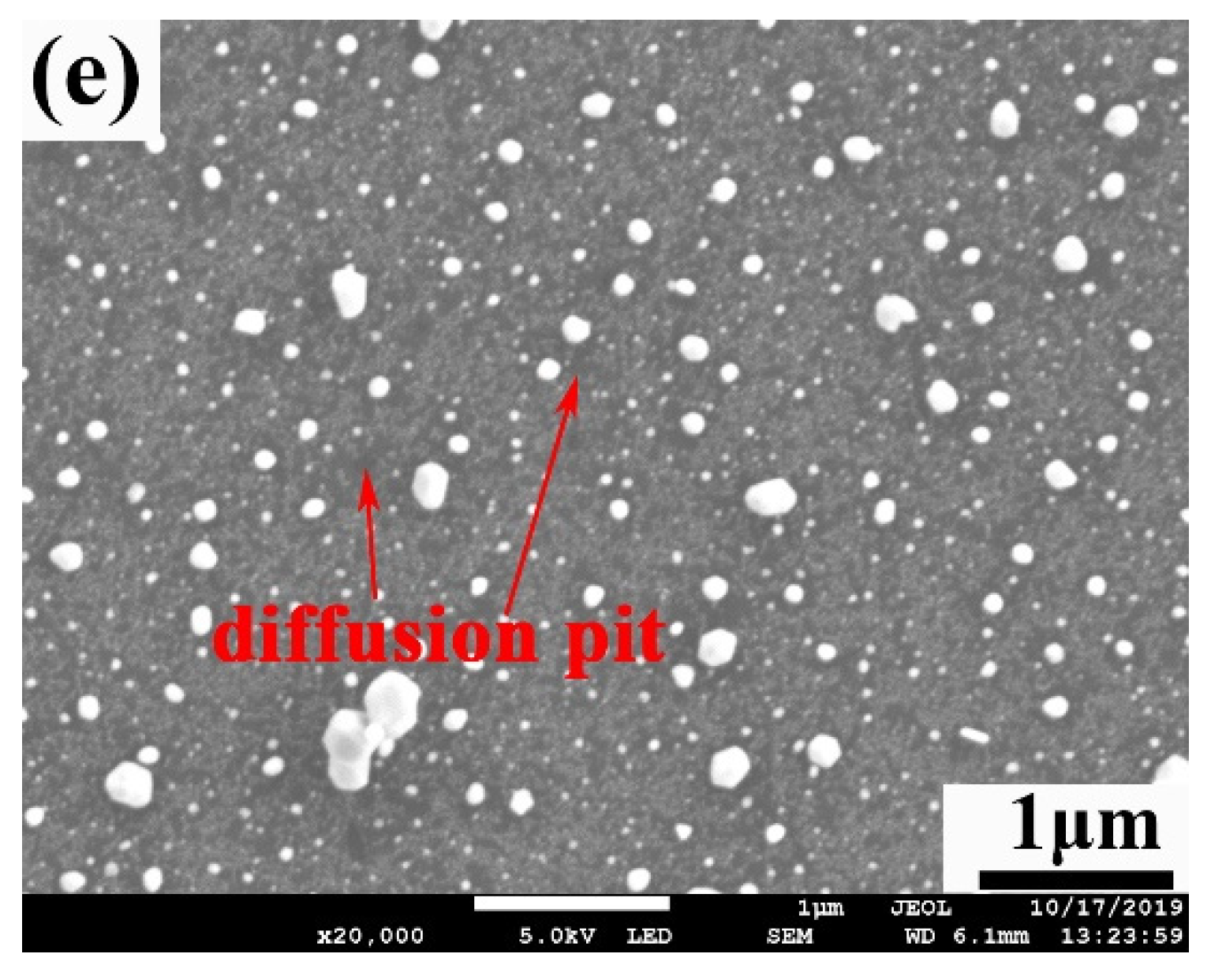
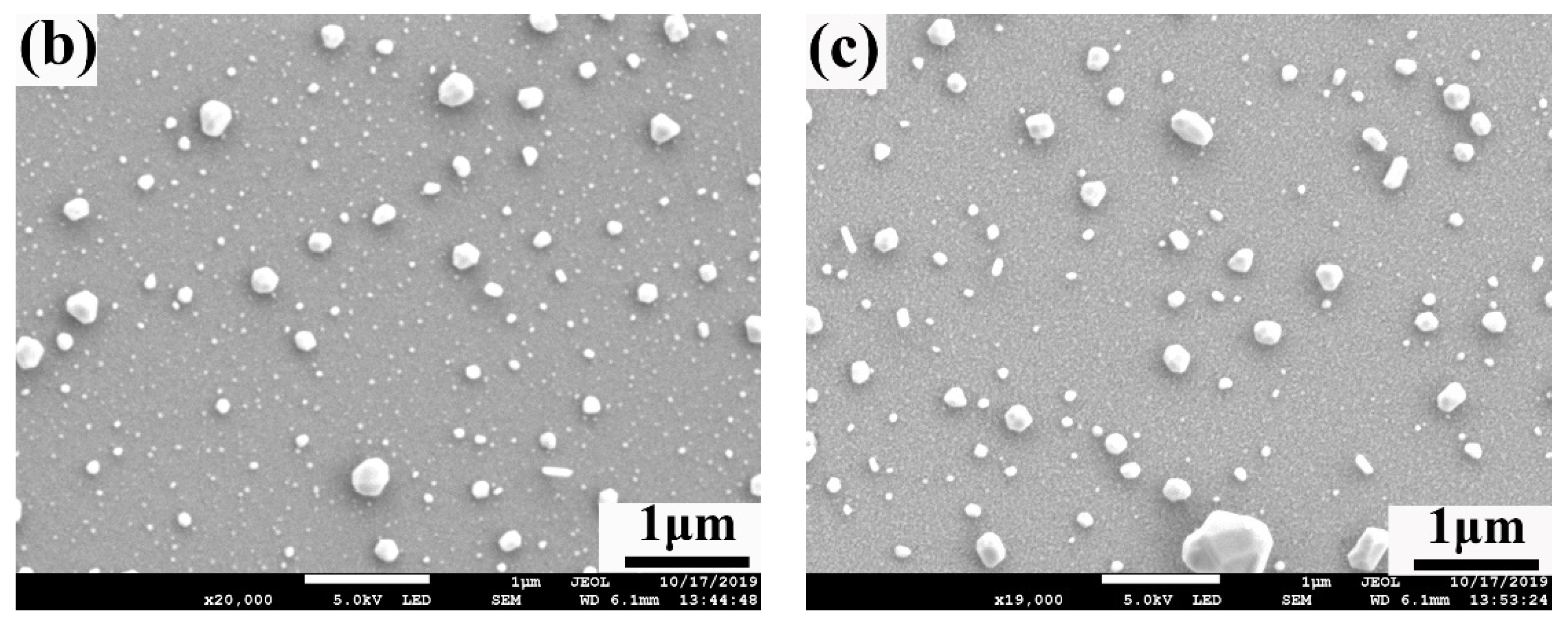
Figure 2b–e exhibit the surface morphology of the Ag-Co films annealed at different temperatures and the EDS result of the as-deposited Ag-Co films. There are no diffusion pits in the Ag-Co films annealed at lower than 160 °C in
Figure 2c, and this film resistivity is lower than that of the as-deposited Ag-Co films. However, it can be seen from
Figure 2d that many diffusion pits form on the surface of 21 nm Ag-Co films annealed at 260 °C and the resistivity of the Ag-Co films increases sharply due to the formation of diffusion pits blocking the in-film migration of electrons under the electric field. More seriously, the resistivity of the Ag-Co films annealed at 360 °C cannot be measured, ascribed to diffusion pits [
22] amplifying, as shown in
Figure 2e, to further limit the transmission of electrons.
3.3. The Analysis of Ultra-High Resistivity of Ag-Co Films
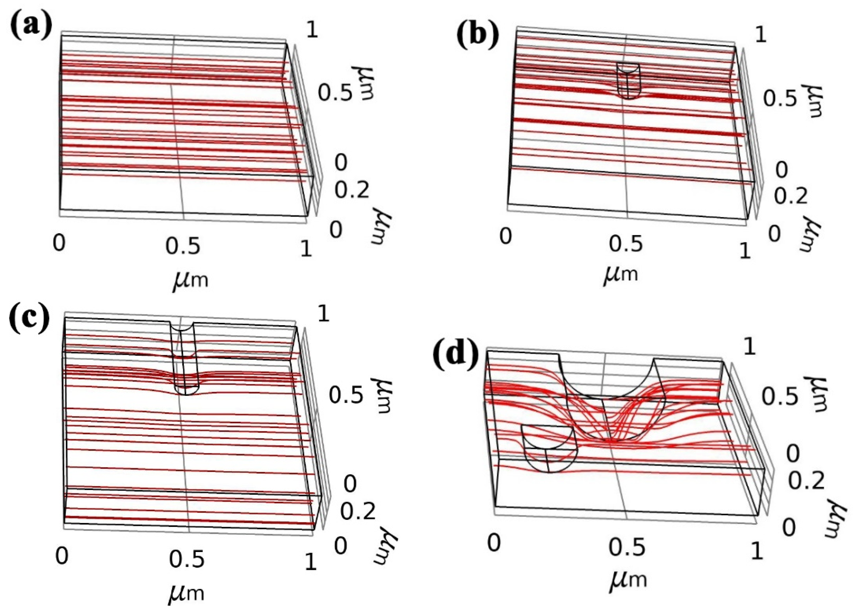
Ion trajectory could respond to the transport and migration direction of electrons, which could reveal the variation of resistivity in Ag-Co films. We employed COMSOL Multiphysics software to build the film simulation model with defects and calculate the negative ion trajectory in the films, as shown in
Figure 3a–d.
Figure 3a shows the negative ion trajectory of films without any surface defects, and it can be found that the trajectory tracking presents straight lines, which indicates that films without any defects could display a low resistance to the transport of electrons. However, as surface defects form on films, the negative ion trajectories are deflected and the routes of electrons in films are increased, as shown in
Figure 3b. Abundant diffusion pits on the film surface of Ag-Co films, as shown in
Figure 2b–e, could increase the migration routes of electrons, which increases the resistivity of Ag-Co films. The routes of electrons in films become more curved and even broken as the surface defects become larger and increase in number, as shown in
Figure 3c,d, which blocks and even cuts off the migration paths of electrons. Thus, the resistivity of Ag-Co films increases with the rise of annealing temperatures due to the formation of diffusion pits.
3.4. Resistivity of Annealed Ag-Co Films with Different Thicknesses
Figure 4a shows the resistivity of annealed Ag-18.9at% Co films with different thicknesses. It can be found from
Figure 4a that the resistivity of Ag-18.9at% Co films decreases with the increase of film thicknesses after annealing at the same temperature, owing to thicker film thickness with better crystallinity [
2,
20]. As annealing temperatures increase from room temperature to 160 °C, the resistivity of Ag-18.9at% Co films decreases due to better crystallinity after annealing at lower than 160 °C. Furthermore, when annealing temperatures are lower than 160 °C, the resistivity of thin Ag-Co films (≤ 21 nm) is several times that of thick Ag-Co films (≥ 45 nm) due to the better crystallinity of thicker Ag-Co films. However, as annealing temperatures rise further, the resistivity of thin Ag-Co films sharply increases. It can be worth noting that the resistivity of thin Ag-Co films is more than 100 times that of thick Ag-Co films after being annealed at 260 °C, owing to the formation of numerous diffusion pits.
When Ag-Co film thickness is 8 nm, film resistivity increases with the increase of annealing temperature because the surface of thinner Ag-Co films is more sensitive to annealing temperature. Thus, the formation of many diffusion pits in the annealed films results in the decrease of Ag-Co film conductivity. When film thickness increases to 12 nm and 21 nm, film resistivity reduces first and then increases due to diffusion pits in Ag-Co films after annealing at higher than 260 °C. Alternatively, when the film thickness is more than 45 nm, the resistivity of Ag-Co films decreases with increasing annealing temperatures because of no diffusion pits and better crystallinity as shown in
Figure 4b,c.
3.5. Resistivity of Ag-Co Films with Different Co Contents
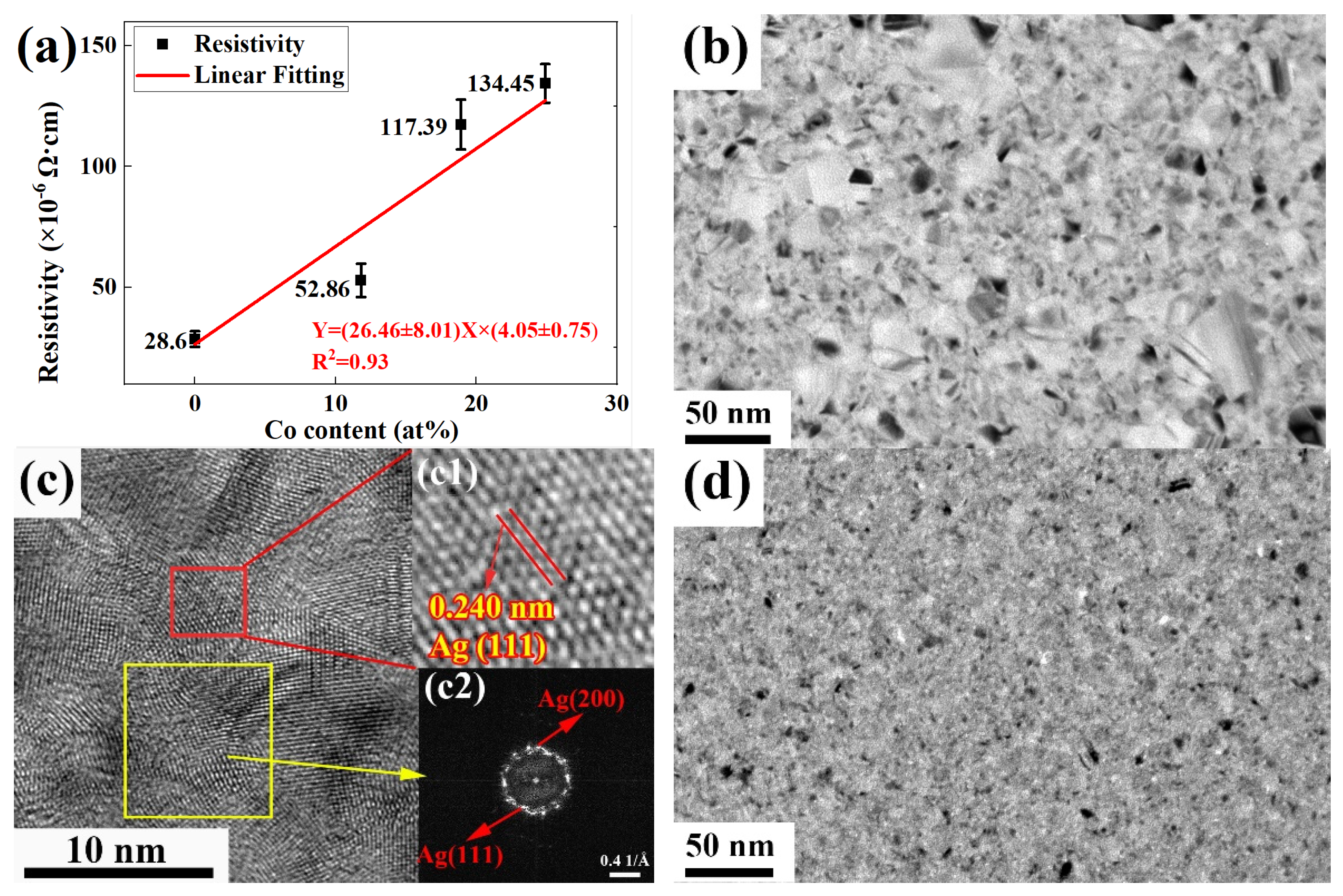
It can be found that the resistivity of the Ag films is much higher than that of the theoretical value of 1.65 × 10
−6 Ω·cm and that the resistivity of the Ag-Co films increases from 28.6 × 10
−6 Ω cm to 134.45 × 10
−6 Ω cm with the addition of more Co, as shown in
Figure 5a. Obviously, there are many vacancies, dislocations and other kinds of defects in the Ag films, as shown in
Figure 5c, to block electron migration, and therefore the resistivity of the Ag films is much higher than the theoretical. Moreover, the addition of Co in the films increases film resistivity and Ag-Co film resistivity increases with the increase of Co contents.
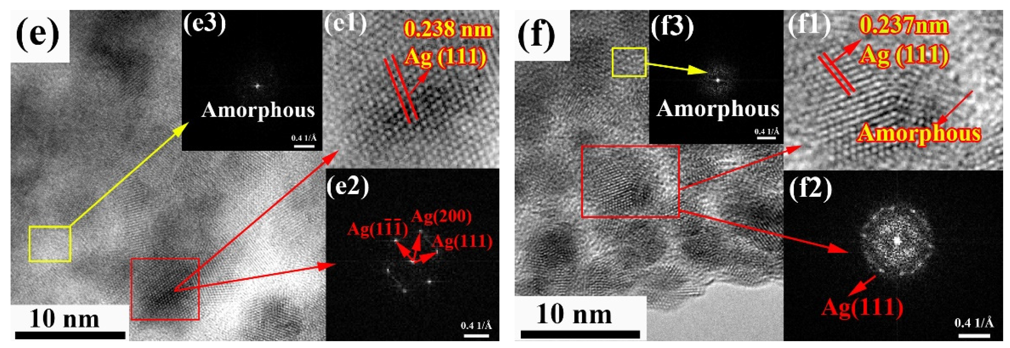
To understand the effect of Co contents on the resistivity of Ag alloy films, TEM was used to observe the microstructure of the Ag films and Ag-Co films. It can be clearly observed from
Figure 5b–f that the grains are Ag grains, proven by the interplanar spacing in
Figure 5(c1,e1,f1) and the fast Fourier transfer (FFT) images in
Figure 5(c2,e2,f2), but no Co diffraction ring can be found in the FFT images of
Figure 5e,f. Furthermore, amorphous matrices could be observed from the FFT images in
Figure 5(e3,f3), which are deduced as amorphous Co matrices. It is worth noting that the size of the Ag grains in the Ag-Co films is much smaller than that in the Ag films, which implies the addition of Co inhibits the growth of Ag grains (compare
Figure 5b,d). Furthermore, more defects and grain boundaries are formed in Ag-Co films, as shown in
Figure 5d–f, to block the transmission of electrons to increase the resistivity of Ag-Co films.
4. Conclusions
The high resistivity of Ag-Co films is related to film thicknesses, annealing temperatures and Co contents. It was found that the Ag-Co film resistivity decreases with the increase of film thicknesses due to the better crystallinity of thicker Ag-Co films. Furthermore, the resistivity of Ag-Co films increases with the increase of Co contents due to the block effect of longer grain boundaries and defects. When annealing temperatures are lower than 160 °C, the resistivity of thin Ag-Co films (≤21 nm) is several times that of thick Ag-Co films (≥45 nm). Alternatively, when annealing temperatures are more than 160 °C, the resistivity of 45 nm Ag-Co films is less than 1/100 times that of 21 nm Ag-Co films due to no diffusion pits and better crystallinity in Ag-Co films. Thin Ag-Co films with ultra-high film resistivity may become a potential candidate for high-resistance devices.
Author Contributions
Y.L.: writing—original draft, writing—review and editing, data curation, investigation. H.S.: writing—review and editing, visualization, conceptualization, resources. P.S.: writing—review, data curation, software. X.L.: writing—review and editing, data curation, software. H.Z.: writing—review. S.L. (Saibo Li): writing—review, data curation. S.L. (Shihao Liang): writing—review. G.W.: writing—review and editing, resources. F.M.: writing—review and editing. All authors have read and agreed to the published version of the manuscript.
Funding
This research work was funded by National Natural Science Foundation of China, grant number U1204521 and National Undergraduate Entrepreneurship Training Program, grant number 202010464013.
Institutional Review Board Statement
Not applicable.
Informed Consent Statement
Not applicable.
Data Availability Statement
The data that support the findings of this study are available from the corresponding authors on reasonable request.
Conflicts of Interest
We declare that we have no financial and personal relationships with other people or organizations that can inappropriately influence our work, there is no professional or other personal interest of any nature or kind in any product, service and/or company that could be construed as influencing the position presented in, or the review of, the manuscript entitled.
References
- Zhu, W.; Chen, T.P.; Liu, Y.; Fung, S. Conduction Mechanisms at Low- and High-Resistance States in Aluminum/Anodic Aluminum Oxide/Aluminum Thin Film Structure. J. Appl. Phys. 2012, 112, 063706. [Google Scholar] [CrossRef] [Green Version]
- Wang, X.; Zhang, Z.; Bai, T.; Liu, Z. Thin Film Chip Resistors with High Resistance and Low Temperature Coefficient of Resistance. Trans. Tianjin Univ. 2010, 16, 348–353. [Google Scholar] [CrossRef]
- Abeles, B.; Pinch, H.L.; Gittleman, J.I. Percolation Conductivity in W-Al2O3Granular Metal Films. Phys. Rev. Lett. 1975, 35, 247–250. [Google Scholar] [CrossRef]
- Han, S.Z.; Lim, S.H.; Kim, S.; Lee, J.; Goto, M.; Kim, H.G.; Han, B.; Kim, K.H. Increasing Strength and Conductivity of Cu Alloy Through Abnormal Plastic Deformation of an Intermetallic Compound. Sci. Rep. 2016, 6, 30907. [Google Scholar] [CrossRef] [PubMed] [Green Version]
- Zhang, Z.Y.; Sun, L.X.; Tao, N.R. Nanostructures and Nanoprecipitates Induce High Strength and High Electrical Conductivity in a CuCrZr Alloy. J. Mater. Sci. Technol. 2020, 48, 18–22. [Google Scholar] [CrossRef]
- Hayashi, T.; Suzuki, T.; Ema, Y. A Very-High-Conductivity of In-Doped CdTe Film. J. Appl. Phys. 1988, 27, 1626–1629. [Google Scholar] [CrossRef]
- Sakai, Y.; Schneider-Muntau, H.J. Ultra-High Strength, High Conductivity Cu-Ag Alloy Wires. Acta Mater. 1997, 45, 1017–1023. [Google Scholar] [CrossRef]
- Lu, K.; Yao, R.; Hu, S.; Liu, X.; Wei, J.; Wu, W.; Ning, H.; Xu, M.; Lan, L.; Peng, J. High-Performance and Flexible Neodymium-Doped Oxide Semiconductor Thin-Film Transistors with Copper Alloy Bottom-Gate Electrode. IEEE Electron Device Lett. 2018, 39, 839–842. [Google Scholar] [CrossRef]
- Wang, X.Y.; Zhang, Z.S.; Bai, T. Investigation on Powder Metallurgy Cr–Si–Ta–Al Alloy target for High-Resistance Thin Film Resistors with Low Temperature Coefficient of Resistance. Mater. Des. 2010, 31, 1302–1307. [Google Scholar] [CrossRef]
- Yang, Y.C.; Tsau, C.H.; Yeh, J.W. TiFeCoNi Oxide Thin Film—A New Composition with Extremely Low Electrical Resistivity at Room Temperature. Scr. Mater. 2011, 64, 173–176. [Google Scholar] [CrossRef]
- Tsau, C.H.; Yang, Y.C.; Lee, C.C.; Wu, L.Y.; Huang, H.J. The Low Electrical Resistivity of the High-entropy Alloy Oxide Thin Films. Procedia Eng. 2012, 36, 246–252. [Google Scholar] [CrossRef] [Green Version]
- Klissurski, D.G. On the Approximate Correlation between the Bonding Energy of Oxygen in Metal Oxides and the Width of Their Forbidden Zones. Solid State Commun. 1974, 15, 1789–1792. [Google Scholar] [CrossRef]
- Fischer, D.W. Vanadium LII, IIIX-Ray Emission and Absorption Spectra from Metal, Oxides, Nitride, Carbide, and Boride. J. Appl. Phys. 1969, 40, 4151–4163. [Google Scholar] [CrossRef]
- Zhang, Q.-F.; Wang, L.-S.; Wang, X.-Z.; Zheng, H.-F.; Liu, X.; Xie, J.; Qiu, Y.-L.; Chen, Y.; Peng, D.-L. Electrical Transport Properties in Co Nanocluster-Assembled Granular Film. J. Appl. Phys. 2017, 121, 103901. [Google Scholar] [CrossRef]
- Bai, G.; Wu, C.; Jin, J.; Yan, M. Structural, Electron Transportation and Magnetic Behavior Transition of Metastable FeAlO Granular Films. Sci. Rep. 2016, 6, 24410. [Google Scholar] [CrossRef] [PubMed] [Green Version]
- Delimova, L.A.; Gushchina, E.V.; Zaitseva, N.V.; Seregin, D.S.; Vorotilov, K.A.; Sigov, A.S. Effect of the Crystal Structure on the Electrical Properties of Thin-Film PZT Structures. Phys. Solid State 2018, 60, 553–558. [Google Scholar] [CrossRef]
- Boff, M.; Canto, B.; Hinrichs, R.; Pereira, L.; Mesquita, F.; Schmidt, J.; Fraga, G. Electrical Current Influence on Resistance and Localization Length of a Co–Al2O3 Granular Thin Film. Phys. B Condens. Matter 2011, 406, 4304–4306. [Google Scholar] [CrossRef] [Green Version]
- Sun, H.; Song, Z.; Ma, F.; Zhan, J.; Xu, K. Microstructure, Formation Mechanism and Compression Plasticity of Regularly Faceted Cu Particles. Scr. Mater. 2009, 60, 305–308. [Google Scholar] [CrossRef]
- Sachan, R.; Yadavali, S.; Shirato, N.; Krishna, H.; Ramos, V.; Duscher, G.; Pennycook, S.J.; Gangopadhyay, A.K.; Garcia, H.; Kalyanaraman, R. Self-organized bimetallic Ag-Co nanoparticles with tunable localized surface plasmons showing high environmental stability and sensitivity. Nanotechnology 2012, 23, 275604. [Google Scholar] [CrossRef] [PubMed]
- Hsieh, J.C.; Liu, C.J.; Ju, Y.H. Response Characteristics of Lead Phthalocyanine Gas Sensor: Effects of Film Thickness and Crystal Morphology. Thin Solid Film. 1998, 322, 98–103. [Google Scholar] [CrossRef]
- Yamamoto, T.; Nozaki, K.; Yamaguchi, A.; Urakami, N. Molecular Simulation of Crystallization in N-Alkane Ultrathin Films: Effects of Film Thickness and Substrate Attraction. J. Chem. Phys. 2007, 127, 154704. [Google Scholar] [CrossRef] [PubMed]
- Tenailleau, C.; Aharon, S.; Cohen, B.E.; Etgar, L. Cell Refinement of CsPbBr3 Perovskite Nanoparticles and Thin Films. Nanoscale Adv. 2019, 1, 147–153. [Google Scholar] [CrossRef] [Green Version]
| Publisher’s Note: MDPI stays neutral with regard to jurisdictional claims in published maps and institutional affiliations. |
© 2022 by the authors. Licensee MDPI, Basel, Switzerland. This article is an open access article distributed under the terms and conditions of the Creative Commons Attribution (CC BY) license (https://creativecommons.org/licenses/by/4.0/).


