
Application of Response Surface Methodology for Optimization of Nanosized Zinc Oxide Synthesis Conditions by Electrospinning Technique

 , , , and
Abstract
:1. Introduction
2. Materials and Methods
2.1. Materials
2.2. ZnAc-PVP Nanofiber Preparation and ZnO Synthesis
2.3. Experimental Design, Statistical Analysis, and Optimization by RSM
2.4. Characterization
3. Results and Discussions
3.1. Response Surface Model
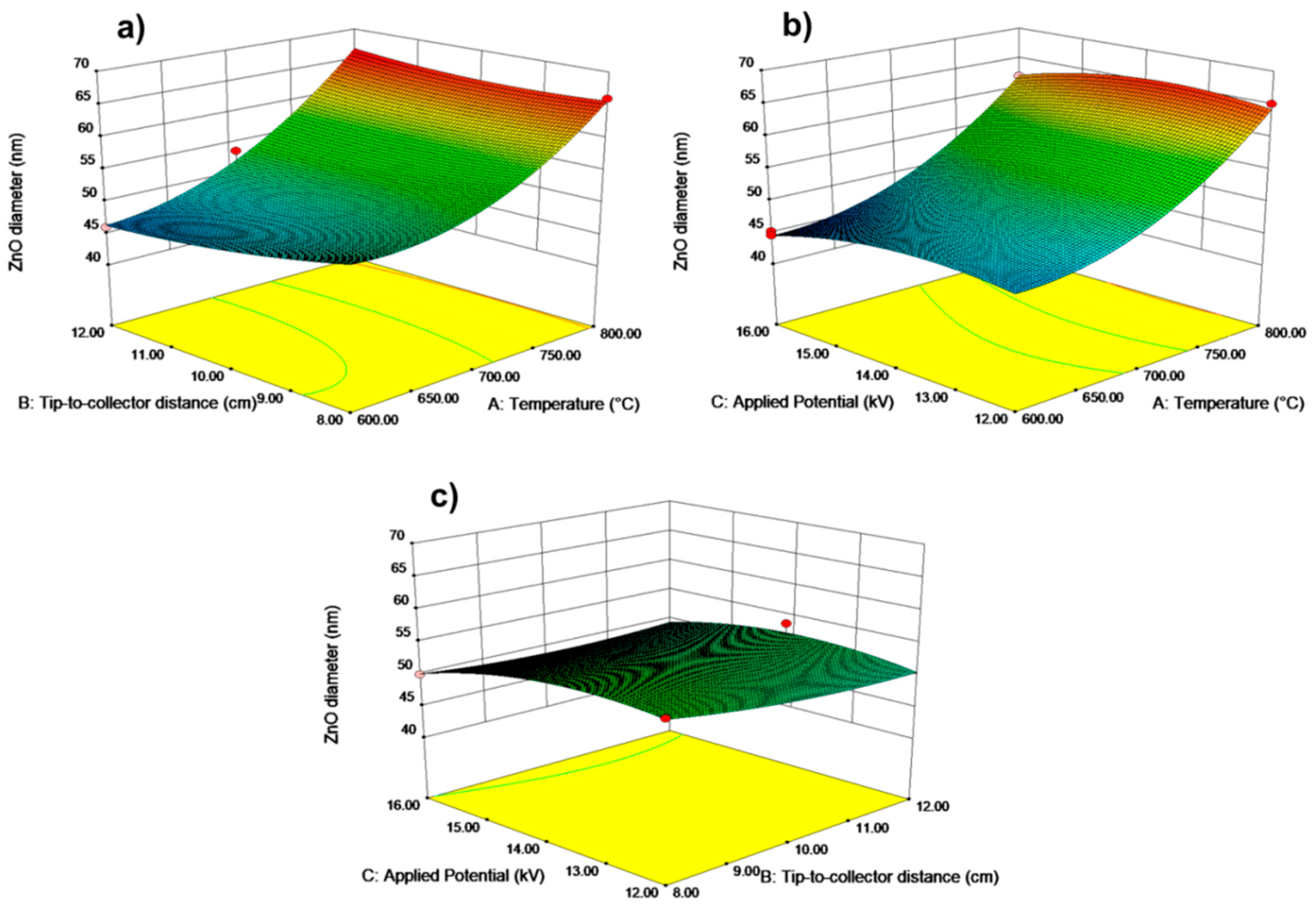
3.2. Response Surface Plots
3.3. Response Surface Plotting and Characterization of ZnO Nanoparticles at Optimized Conditions
3.4. XRD Patterns and Transmission Electron Microscopy (TEM)
4. Conclusions
Author Contributions
Funding
Data Availability Statement
Conflicts of Interest
References
- Choi, K.; Kang, T.; Oh, S.-G. Preparation of disk shaped ZnO particles using surfactant and their PL properties. Mater. Lett. 2012, 75, 240–243. [Google Scholar] [CrossRef]
- Ahangar, E.G.; Abbaspour-Fard, M.H.; Shahtahmassebi, N.; Khojastehpour, M.; Maddahi, P. Preparation and Characterization of PVA/ZnO Nanocomposite. J. Food Processing Preserv. 2015, 39, 1442–1451. [Google Scholar] [CrossRef]
- Ong, C.B.; Ng, L.Y.; Mohammad, A.W. A review of ZnO nanoparticles as solar photocatalysts: Synthesis, mechanisms and applications. Renew. Sustain. Energy Rev. 2018, 81, 536–551. [Google Scholar] [CrossRef]
- Baig, N.; Kammakakam, I.; Falath, W. Nanomaterials: A review of synthesis methods, properties, recent progress, and challenges. Mater. Adv. 2021, 2, 1821–1871. [Google Scholar] [CrossRef]
- Nair, A.K.; Mayeen, A.; Shaji, L.K.; Kala, M.S.; Thomas, S.; Kalarikkal, N. Optical Characterization of Nanomaterials. In Characterization of Nanomaterials; Elsevier: Amsterdam, The Netherlands, 2018; pp. 269–299. [Google Scholar]
- Malakar, A.; Kanel, S.R.; Ray, C.; Snow, D.D.; Nadagouda, M.N. Nanomaterials in the environment, human exposure pathway, and health effects: A review. Sci. Total Environ. 2021, 759, 143470. [Google Scholar] [CrossRef]
- Jayanthi, K.; Chawla, S.; Chander, H.; Haranath, D. Structural, optical and photoluminescence properties of ZnS: Cu nanoparticle thin films as a function of dopant concentration and quantum confinement effect. Cryst. Res. Technol. 2007, 42, 976–982. [Google Scholar] [CrossRef]
- Wang, X.; Hanson, J.C.; Liu, G.; Rodriguez, J.A.; Iglesias-Juez, A.; Fernández-García, M. The behavior of mixed-metal oxides: Physical and chemical properties of bulk Ce1−xTbxO2 and nanoparticles of Ce1−xTbxOy. J. Chem. Phys. 2004, 121, 5434–5444. [Google Scholar] [CrossRef] [Green Version]
- Chavali, M.S.; Nikolova, M.P. Metal oxide nanoparticles and their applications in nanotechnology. SN Appl. Sci. 2019, 1, 607. [Google Scholar] [CrossRef] [Green Version]
- Sun, Q.; Xu, Y.; Gao, Z.; Zhou, H.; Zhang, Q.; Xu, R.; Zhang, C.; Yao, H.; Liu, M. High-Performance Surface-Enhanced Raman Scattering Substrates Based on the ZnO/Ag Core-Satellite Nanostructures. Nanomaterials 2022, 12, 1286. [Google Scholar] [CrossRef]
- Duangmanee, S.; Poo-Arporn, Y.; Janphuang, P.; Leuasoongnoen, P.; Tonlublao, S.; Kamonpha, P.; Saengchai, N.; Chanlek, N.; Saisombat, C.; Kidkhunthod, P.; et al. An Operando X-ray Absorption Spectroscopy Study on Sensing Characteristics of Vertically Aligned ZnO Thin Film for Methane Gas Sensors. Nanomaterials 2022, 12, 1285. [Google Scholar] [CrossRef]
- Siddheswaran, R.; Sankar, R.; Ramesh Babu, M.; Rathnakumari, M.; Jayavel, R.; Murugakoothan, P.; Sureshkumar, P. Preparation and characterization of ZnO nanofibers by electrospinning. Cryst. Res. Technol. J. Exp. Ind. Crystallogr. 2006, 41, 446–449. [Google Scholar] [CrossRef]
- Khan, I.; Saeed, K.; Khan, I. Nanoparticles: Properties, applications and toxicities. Arab. J. Chem. 2019, 12, 908–931. [Google Scholar] [CrossRef]
- Wang, L.; Kang, Y.; Liu, X.; Zhang, S.; Huang, W.; Wang, S. ZnO nanorod gas sensor for ethanol detection. Sensors Actuators B Chem. 2012, 162, 237–243. [Google Scholar] [CrossRef]
- Viter, R.; Chaaya, A.A.; Iatsunskyi, I.; Nowaczyk, G.; Kovalevskis, K.; Erts, D.; Miele, P.; Smyntyna, V.; Bechelany, M. Tuning of ZnO 1D nanostructures by atomic layer deposition and electrospinning for optical gas sensor applications. Nanotechnology 2015, 26, 105501. [Google Scholar] [CrossRef] [PubMed]
- Franco, M.A.; Conti, P.P.; Andre, R.S.; Correa, D.S. A review on chemiresistive ZnO gas sensors. Sensors Actuators Rep. 2022, 4, 100100. [Google Scholar] [CrossRef]
- Xuan, J.; Zhao, G.; Sun, M.; Jia, F.; Wang, X.; Zhou, T.; Yin, G.; Liu, B. Low-temperature operating ZnO-based NO2 sensors: A review. RSC Adv. 2020, 10, 39786–39807. [Google Scholar] [CrossRef]
- Bolarinwa, H.; Onuu, M.; Fasasi, A.; Alayande, S.O.; Animasahun, L.; Abdulsalami, I.; Fadodun, O.; Egunjobi, I. Determination of optical parameters of zinc oxide nanofibre deposited by electrospinning technique. J. Taibah Univ. Sci. 2017, 11, 1245–1258. [Google Scholar] [CrossRef]
- Wang, S.-X.; Yap, C.C.; He, J.; Chen, C.; Wong, S.Y.; Li, X. Electrospinning: A facile technique for fabricating functional nanofibers for environmental applications. Nanotechnol. Rev. 2016, 5, 51–73. [Google Scholar] [CrossRef] [Green Version]
- Shin, Y.M.; Hohman, M.M.; Brenner, M.P.; Rutledge, G.C. Electrospinning: A whipping fluid jet generates submicron polymer fibers. Appl. Phys. Lett. 2001, 78, 1149–1151. [Google Scholar] [CrossRef]
- Banikazemi, S.; Rezaei, M.; Rezaei, P.; Babaie, A.; Eyvazzadeh-Kalajahi, A. Preparation of electrospun shape memory polyurethane fibers in optimized electrospinning conditions via response surface methodology. Polym. Adv. Technol. 2020, 31, 2199–2208. [Google Scholar] [CrossRef]
- Baji, A.; Mai, Y.-W. Engineering ceramic fiber nanostructures through polymer-mediated electrospinning. In Polymer-Engineered Nanostructures for Advanced Energy Applications; Springer: Berlin, Germany, 2017; pp. 3–30. [Google Scholar]
- Vuong, N.M.; Chinh, N.D.; Huy, B.T.; Lee, Y.I. CuO-decorated ZnO hierarchical nanostructures as efficient and established sensing materials for H2S gas sensors. Sci. Rep. 2016, 6, 26736. [Google Scholar] [CrossRef] [PubMed] [Green Version]
- Shingange, K.; Swart, H.; Mhlongo, G. H2S detection capabilities with fibrous-like La-doped ZnO nanostructures: A comparative study on the combined effects of La-doping and post-annealing. J. Alloy. Compd. 2019, 797, 284–301. [Google Scholar] [CrossRef]
- Kumar, V.; Singh, N.; Kumar, V.; Purohit, L.P.; Kapoor, A.; Ntwaeaborwa, O.M.; Swart, H.C. Doped zinc oxide window layers for dye sensitized solar cells. J. Appl. Phys. 2013, 114, 134506. [Google Scholar] [CrossRef]
- Ren, X.; Ying, P.; Yang, Z.; Shang, M.; Hou, H.; Gao, F. Foaming-assisted electrospinning of large-pore mesoporous ZnO nanofibers with tailored structures and enhanced photocatalytic activity. RSC Adv. 2015, 5, 16361–16367. [Google Scholar] [CrossRef]
- Ghafari, E.; Feng, Y.; Liu, Y.; Ferguson, I.; Lu, N. Investigating process-structure relations of ZnO nanofiber via electrospinning method. Compos. Part B Eng. 2017, 116, 40–45. [Google Scholar] [CrossRef] [Green Version]
- Di Mauro, A.; Zimbone, M.; Fragala, M.E.; Impellizzeri, G. Synthesis of ZnO nanofibers by the electrospinning process. Mater. Sci. Semicond. Processing 2016, 42, 98–101. [Google Scholar] [CrossRef]
- Oliveira, V.H.; da Silva, E.P.; de Marques, V.S.; Rubira, A.F.; Silva, R.; Cava, C.E.; Lourenço, S.A.; Muniz, E.C. Electrospun fibers of poly (vinyl alcohol): Zinc acetate (PVA: AcZn) and further ZnO production: Evaluation of PVA: AcZn ratio and annealing temperature effects on ZnO structure. J. Nanoparticle Res. 2020, 22, 322. [Google Scholar] [CrossRef]
- Borkowski, J.J. Graphical methods for assessing the prediction capability of response surface designs. In Response Surface Methodology and Related Topics; World Scientific: Hackensack, NJ, USA, 2006; pp. 349–378. [Google Scholar]
- Roudi, A.M.; Salem, S.; Abedini, M.; Maslahati, A.; Imran, M. Response Surface Methodology (RSM)-Based Prediction and Optimization of the Fenton Process in Landfill Leachate Decolorization. Processes 2021, 9, 2284. [Google Scholar] [CrossRef]
- Pereao, O.; Laatikainen, K.; Bode-Aluko, C.; Fatoba, O.; Omoniyi, E.; Kochnev, Y.; Nechaev, A.; Apel, P.; Petrik, L. Synthesis and characterisation of diglycolic acid functionalised polyethylene terephthalate nanofibers for rare earth elements recovery. J. Environ. Chem. Eng. 2021, 9, 105902. [Google Scholar] [CrossRef]
- Rakhmanova, A.; Wang, T.; Xing, G.; Ma, L.; Hong, Y.; Lu, Y.; Xin, L.; Xin, W.; Zhu, Q.; Lü, X. Isolation and identification of microorganisms in Kazakhstan koumiss and their application in preparing cow-milk koumiss. J. Dairy Sci. 2021, 104, 151–166. [Google Scholar] [CrossRef]
- Agarwal, P.; Mishra, P.K.; Srivastava, P. Statistical optimization of the electrospinning process for chitosan/polylactide nanofabrication using response surface methodology. J. Mater. Sci. 2012, 47, 4262–4269. [Google Scholar] [CrossRef]
- Ebadi, S.V.; Semnani, D.; Fashandi, H.; Rezaei, B. Synthesis and characterization of a novel polyurethane/polypyrrole-p-toluenesulfonate (PU/PPy-pTS) electroactive nanofibrous bending actuator. Polym. Adv. Technol. 2019, 30, 2261–2274. [Google Scholar] [CrossRef]
- Ghelich, R.; Jahannama, M.R.; Abdizadeh, H.; Torknik, F.S.; Vaezi, M.R. Central composite design (CCD)-Response surface methodology (RSM) of effective electrospinning parameters on PVP-B-Hf hybrid nanofibrous composites for synthesis of HfB2-based composite nanofibers. Compos. Part B Eng. 2019, 166, 527–541. [Google Scholar] [CrossRef]
- Sarlak, N.; Nejad, M.A.F.; Shakhesi, S.; Shabani, K. Effects of electrospinning parameters on titanium dioxide nanofibers diameter and morphology: An investigation by Box–Wilson central composite design (CCD). Chem. Eng. J. 2012, 210, 410–416. [Google Scholar] [CrossRef]
- Li, L.; Jiang, Z.; Xu, J.; Fang, T. Predicting poly(vinyl pyrrolidone)’s solubility parameter and systematic investigation of the parameters of electrospinning with response surface methodology. J. Appl. Polym. Sci. 2013, 131, 40304. [Google Scholar] [CrossRef]
- Dayan, C.B.; Afghah, F.; Okan, B.S.; Yıldız, M.; Menceloglu, Y.; Culha, M.; Koc, B. Modeling 3D melt electrospinning writing by response surface methodology. Mater. Des. 2018, 148, 87–95. [Google Scholar] [CrossRef]
- Chelladurai, S.J.S.; Murugan, K.; Ray, A.P.; Upadhyaya, M.; Narasimharaj, V.; Gnanasekaran, S. Optimization of process parameters using response surface methodology: A review. Mater. Today Proc. 2020, 37, 1301–1304. [Google Scholar] [CrossRef]
- Zhang, Q.N.; Tang, D.Y.; Yu, Z.Q.; Lv, H.T. Preparation of ZnAc/PVP Composite Fibers and ZnO Nanofibers. Appl. Mech. Mater. 2014, 665, 296–299. [Google Scholar] [CrossRef]
- Xue, J.; Wu, T.; Dai, Y.; Xia, Y. Electrospinning and Electrospun Nanofibers: Methods, Materials, and Applications. Chem. Rev. 2019, 119, 5298–5415. [Google Scholar] [CrossRef]
- Ray, S.; Lalman, J.A. Using the Box–Benkhen design (BBD) to minimize the diameter of electrospun titanium dioxide nanofibers. Chem. Eng. J. 2011, 169, 116–125. [Google Scholar] [CrossRef]
- Silva, P.M.; Torres-Giner, S.; Vicente, A.A.; Cerqueira, M.A. Management of Operational Parameters and Novel Spinneret Configurations for the Electrohydrodynamic Processing of Functional Polymers. Macromol. Mater. Eng. 2022, 307, 2100858. [Google Scholar] [CrossRef]
- Zhang, Z.; Zheng, H. Optimization for decolorization of azo dye acid green 20 by ultrasound and H2O2 using response surface methodology. J. Hazard. Mater. 2009, 172, 1388–1393. [Google Scholar] [CrossRef] [PubMed]
- Ghafari, S.; Aziz, H.A.; Isa, M.H.; Zinatizadeh, A.A. Application of response surface methodology (RSM) to optimize coagulation–flocculation treatment of leachate using poly-aluminum chloride (PAC) and alum. J. Hazard. Mater. 2008, 163, 650–656. [Google Scholar] [CrossRef] [PubMed]
- Noordin, M.; Venkatesh, V.; Sharif, S.; Elting, S.; Abdullah, A. Application of response surface methodology in describing the performance of coated carbide tools when turning AISI 1045 steel. J. Mater. Processing Technol. 2004, 145, 46–58. [Google Scholar] [CrossRef] [Green Version]
- Angel, N.; Guo, L.; Yan, F.; Wang, H.; Kong, L. Effect of processing parameters on the electrospinning of cellulose acetate studied by response surface methodology. J. Agric. Food Res. 2019, 2, 100015. [Google Scholar] [CrossRef]
- Bezerra, M.A.; Santelli, R.E.; Oliveira, E.P.; Villar, L.S.; Escaleira, L.A. Response surface methodology (RSM) as a tool for optimization in analytical chemistry. Talanta 2008, 76, 965–977. [Google Scholar] [CrossRef] [PubMed]
- Zhang, J.; Fu, D.; Xu, Y.; Liu, C. Optimization of parameters on photocatalytic degradation of chloramphenicol using TiO2 as photocatalyist by response surface methodology. J. Environ. Sci. 2010, 22, 1281–1289. [Google Scholar] [CrossRef]
- Ba-Abbad, M.M.; Kadhum, A.A.H.; Mohamad, A.B.; Takriff, M.S.; Sopian, K. Optimization of process parameters using D-optimal design for synthesis of ZnO nanoparticles via sol–gel technique. J. Ind. Eng. Chem. 2013, 19, 99–105. [Google Scholar] [CrossRef]
- Ramakrishna, S. An Introduction to Electrospinning and Nanofibers; World Scientific: Singapore, 2005. [Google Scholar]
- Megelski, S.; Stephens, J.S.; Chase, A.D.B.; Rabolt, J.F. Micro- and Nanostructured Surface Morphology on Electrospun Polymer Fibers. Macromolecules 2002, 35, 8456–8466. [Google Scholar] [CrossRef]
- Zhao, S.; Wu, X.; Wang, L.; Huang, Y. Electrospinning of ethyl-cyanoethyl cellulose/tetrahydrofuran solutions. J. Appl. Polym. Sci. 2003, 91, 242–246. [Google Scholar] [CrossRef]
- Lee, J.S.; Choi, K.H.; Ghim, H.D.; Kim, S.S.; Chun, D.H.; Kim, H.Y.; Lyoo, W.S. Role of molecular weight of atactic poly(vinyl alcohol) (PVA) in the structure and properties of PVA nanofabric prepared by electrospinning. J. Appl. Polym. Sci. 2004, 93, 1638–1646. [Google Scholar] [CrossRef]
- Wasim, M.; Sabir, A.; Shafiq, M.; Jamil, T. Electrospinning: A fiber fabrication technique for water purification. In Nanoscale Materials in Water Purification; Thomas, S., Pasquini, D., Leu, S., Gopakuma, D., Eds.; Elsevier Inc.: Amsterdam, The Netherlands, 2019; pp. 289–308. [Google Scholar]
- Xiong, J.; Liu, Y.; Li, A.; Wei, L.; Wang, L.; Qin, X.; Yu, J. Mass production of high-quality nanofibers via constructing pre-Taylor cones with high curvature on needleless electrospinning. Mater. Des. 2020, 197, 109247. [Google Scholar] [CrossRef]
- Krishnappa, R.V.N.; Desai, K.; Sung, C. Morphological study of electrospun polycarbonates as a function of the solvent and processing voltage. J. Mater. Sci. 2003, 38, 2357–2365. [Google Scholar] [CrossRef]
- Alias, S.; Ismail, A.; Mohamad, A.A. Effect of pH on ZnO nanoparticle properties synthesized by sol–gel centrifugation. J. Alloys Compd. 2010, 499, 231–237. [Google Scholar] [CrossRef]
- Jaafar, S.H.; Zaid, M.H.M.; Matori, K.A.; Ab Aziz, S.H.; Kamari, H.M.; Honda, S.; Iwamoto, Y. Influence of Calcination Temperature on Crystal Growth and Optical Characteristics of Eu3+ Doped ZnO/Zn2SiO4 Composites Fabricated via Simple Thermal Treatment Method. Crystals 2021, 11, 115. [Google Scholar] [CrossRef]
- Smith, A.; Nie, S. Semiconductor Nanocrystals: Structure, Properties, and Band Gap Engineering. Accounts Chem. Res. 2009, 43, 190–200. [Google Scholar] [CrossRef] [Green Version]
- Ferreira, D.L.; Sousa, J.C.L.; Maronesi, R.N.; Bettini, J.; Schiavon, M.A.; Teixeira, A.V.N.C.; Silva, A.G. Size-dependent bandgap and particle size distribution of colloidal semiconductor nanocrystals. J. Chem. Phys. 2017, 147, 154102. [Google Scholar] [CrossRef] [Green Version]
- Geetha, M.; Nagabhushana, H.; Shivananjaiah, H. Green mediated synthesis and characterization of ZnO nanoparticles using Euphorbia Jatropa latex as reducing agent. J. Sci. Adv. Mater. Devices 2016, 1, 301–310. [Google Scholar] [CrossRef] [Green Version]
- Debanath, M.; Karmakar, S. Study of blueshift of optical band gap in zinc oxide (ZnO) nanoparticles prepared by low-temperature wet chemical method. Mater. Lett. 2013, 111, 116–119. [Google Scholar] [CrossRef]
- Chitsazi, M.R.; Korbekandi, H.; Asghari, G.; Bahri Najafi, R.; Badii, A.; Iravani, S. Synthesis of silver nanoparticles using methanol and dichloromethane extracts of Pulicaria gnaphalodes (Vent.) Boiss. aerial parts. Artif. Cells Nanomed. Biotechnol. 2016, 44, 328–333. [Google Scholar] [CrossRef]
- Musa, I.; Qamhieh, N.; Mahmoud, S.T. Synthesis and length dependent photoluminescence property of zinc oxide nanorods. Results Phys. 2017, 7, 3552–3556. [Google Scholar] [CrossRef]
- Golsheikh, A.M.; Kamali, K.Z.; Huang, N.M.; Zak, A.K. Effect of calcination temperature on performance of ZnO nanoparticles for dye-sensitized solar cells. Powder Technol. 2018, 329, 282–287. [Google Scholar] [CrossRef] [Green Version]


| Independent Variables | Factor Xi | Range and Level | ||
|---|---|---|---|---|
| −1 | 0 | +1 | ||
| Applied potential (kV) | X1 | 12 | 14 | 16 |
| Distance (cm) | X2 | 8 | 10 | 12 |
| Calcination temperature (°C) | X3 | 600 | 700 | 800 |
| Source | Sum of Squares | df | Mean Square | F Value | p-Value |
|---|---|---|---|---|---|
| Model | 982.28 | 3 | 327.43 | 99.22 | 0.0001 significant |
| A-Temperature | 593.77 | 1 | 593.77 | 179.93 | 0.0001 |
| B-Distance | 0.093 | 1 | 0.093 | 0028 | 0.8697 |
| C-Applied potential | 9.19 | 1 | 9.19 | 2.79 | 0.1233 |
| Residual | 36.30 | 11 | 3.30 | ||
| Lack of fit | 35.62 | 9 | 3.96 | 11.64 | 0.0816 not significant |
| Pure error | 0.68 | 2 | 0.34 | ||
| Cor total | 1018.58 | 14 | |||
| Std. Dev. | 1.82 | R2 | 0.9644 | ||
| Mean | 53.79 | Adj R2 | 0.9546 | ||
| CV % | 3.38 | Pred R-Square | 0.9424 | ||
| PRESS | 58.71 | Adequate Precision | 22.609 |
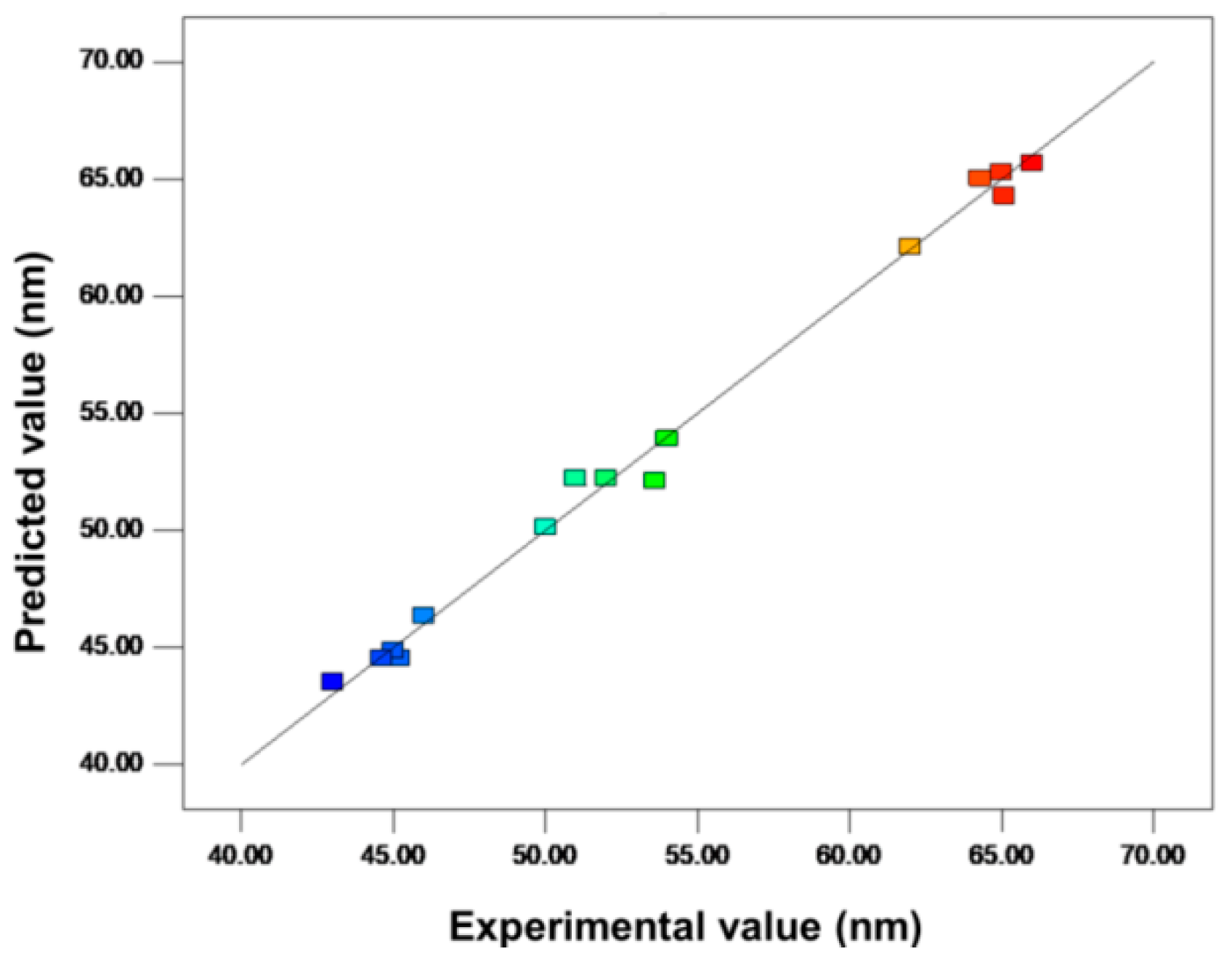
| Run Order | Calcination Temperature (°C) | Tip-to-Collector Distance (cm) | Applied Potential (kV) | Response, Y (ZnO Size in nm) | Predicted Values (ZnO Size in nm) |
|---|---|---|---|---|---|
| 1 | 800 | 8.00 | 14.00 | 66 | 65.68 |
| 2 | 800 | 8.00 | 12.00 | 65 | 65.30 |
| 14 | 600 | 10.00 | 16.00 | 46 | 46.34 |
| 9 | 700 | 8.00 | 12.00 | 64.30 | 65.03 |
| 8 | 800 | 10.00 | 16.00 | 45.20 | 44.52 |
| 10 | 600 | 12.00 | 12.00 | 65.10 | 64.28 |
| 5 | 600 | 8.00 | 16.00 | 53.60 | 52.12 |
| 6 | 800 | 10.00 | 12.00 | 62.00 | 62.11 |
| 7 | 700 | 12.00 | 14.00 | 54.00 | 53.90 |
| 11 | 700 | 8.00 | 16.00 | 45.00 | 44.88 |
| 15 | 700 | 10.00 | 14.00 | 50.00 | 50.12 |
| 3 | 600 | 12.00 | 14.00 | 44.00 | 44.50 |
| 13 | 700 | 10.00 | 14.00 | 52.00 | 52.23 |
| 4 | 800 | 12.00 | 12.00 | 44.60 | 44.52 |
| 12 | 600 | 12.00 | 16.00 | 43.00 | 43.23 |
Publisher’s Note: MDPI stays neutral with regard to jurisdictional claims in published maps and institutional affiliations. |
© 2022 by the authors. Licensee MDPI, Basel, Switzerland. This article is an open access article distributed under the terms and conditions of the Creative Commons Attribution (CC BY) license (https://creativecommons.org/licenses/by/4.0/).
Share and Cite
Rakhmanova, A.; Kalybekkyzy, S.; Soltabayev, B.; Bissenbay, A.; Kassenova, N.; Bakenov, Z.; Mentbayeva, A. Application of Response Surface Methodology for Optimization of Nanosized Zinc Oxide Synthesis Conditions by Electrospinning Technique. Nanomaterials 2022, 12, 1733. https://doi.org/10.3390/nano12101733
Rakhmanova A, Kalybekkyzy S, Soltabayev B, Bissenbay A, Kassenova N, Bakenov Z, Mentbayeva A. Application of Response Surface Methodology for Optimization of Nanosized Zinc Oxide Synthesis Conditions by Electrospinning Technique. Nanomaterials. 2022; 12(10):1733. https://doi.org/10.3390/nano12101733
Chicago/Turabian StyleRakhmanova, Aizhan, Sandugash Kalybekkyzy, Baktiyar Soltabayev, Aiman Bissenbay, Nazym Kassenova, Zhumabay Bakenov, and Almagul Mentbayeva. 2022. "Application of Response Surface Methodology for Optimization of Nanosized Zinc Oxide Synthesis Conditions by Electrospinning Technique" Nanomaterials 12, no. 10: 1733. https://doi.org/10.3390/nano12101733