
Iron Oxide/Polymer Core–Shell Nanomaterials with Star-like Behavior

 ,
,
Abstract
:1. Introduction
2. Materials and Methods
2.1. Materials
2.2. Methods of Synthesis
2.2.1. NPs
2.2.2. Polymer Coating
2.3. Methods of Characterization
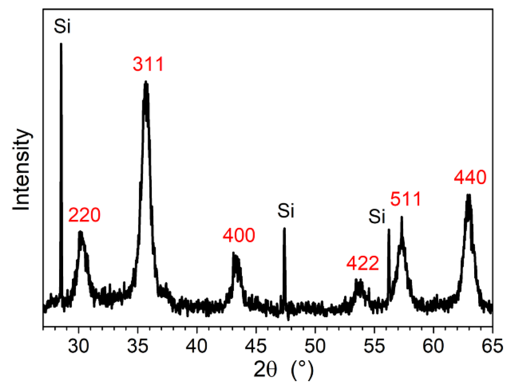
2.3.1. Powder X-ray Diffraction (PXRD)
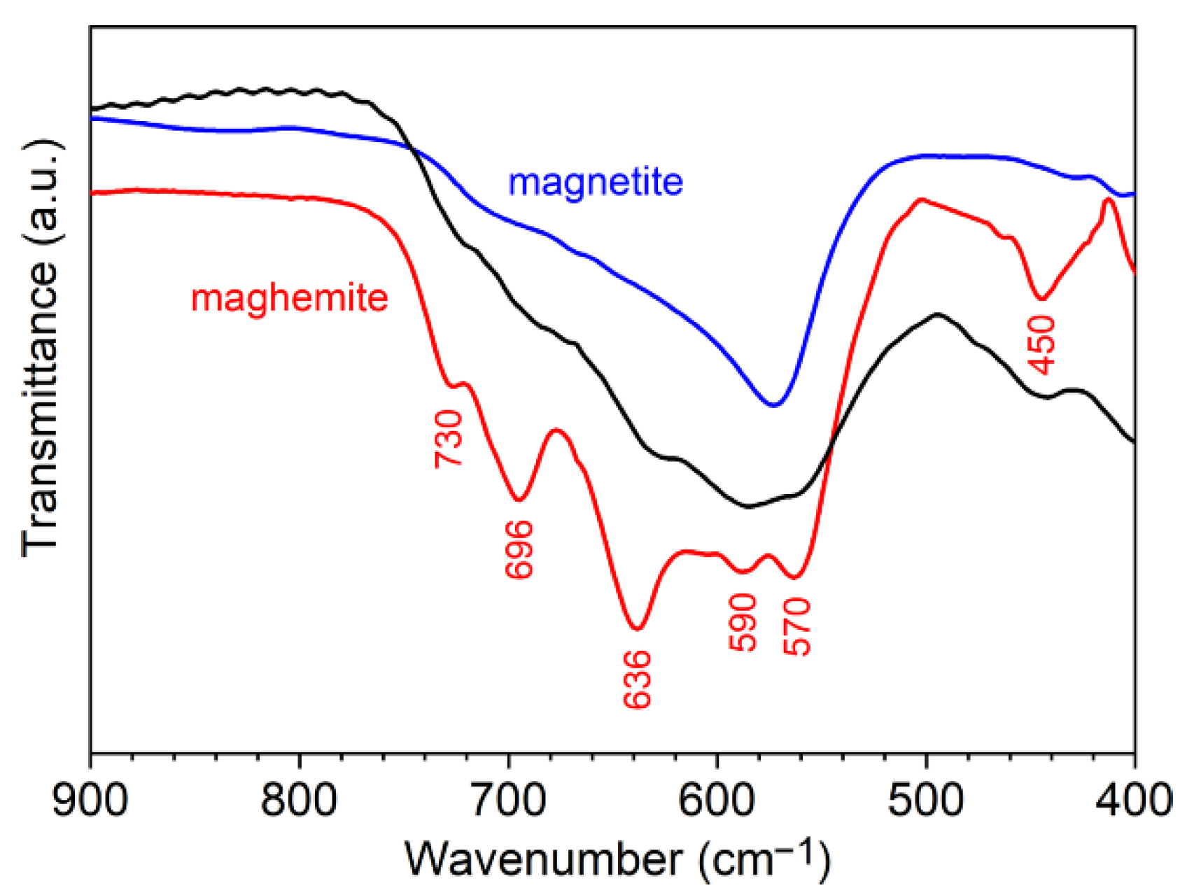
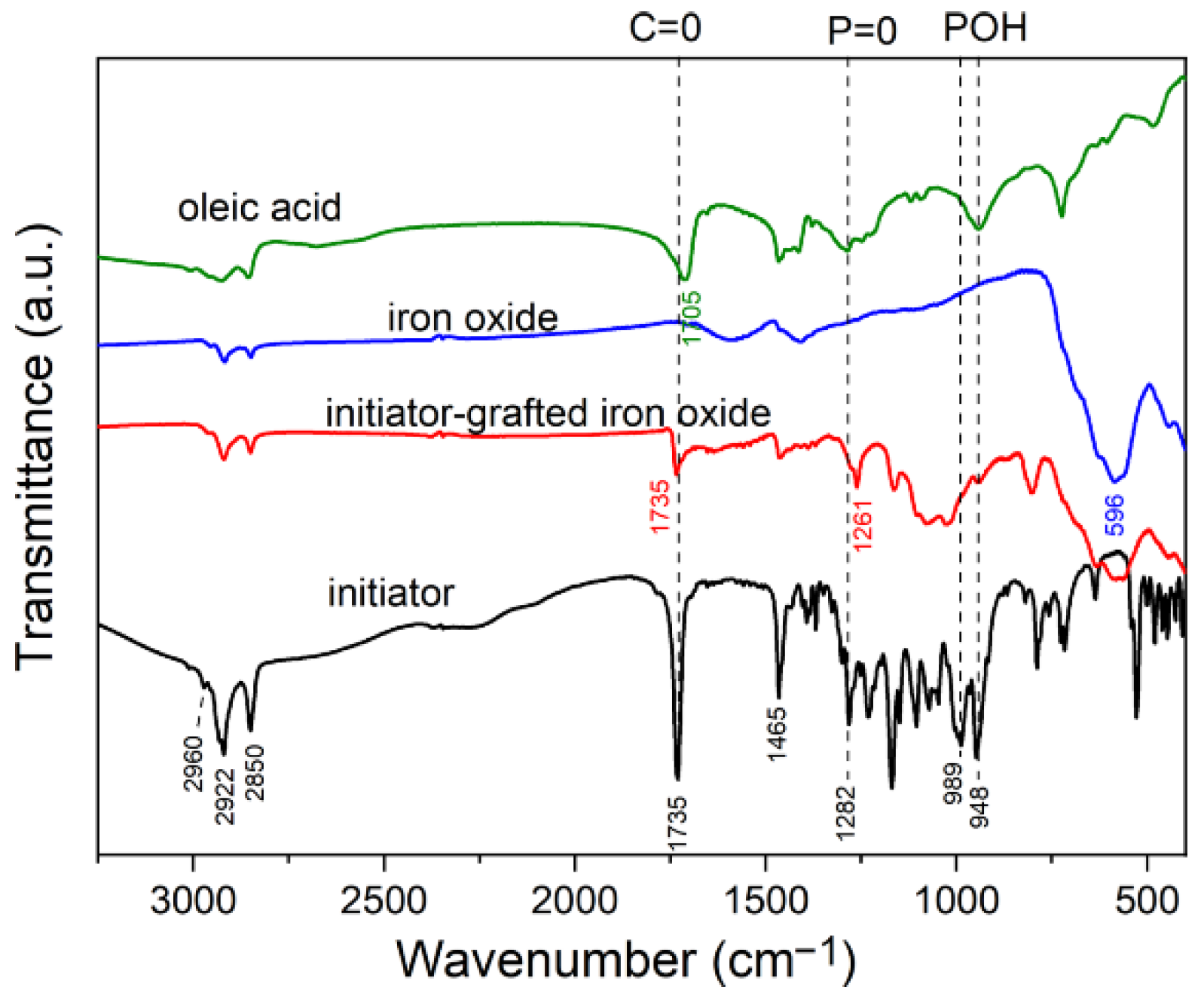
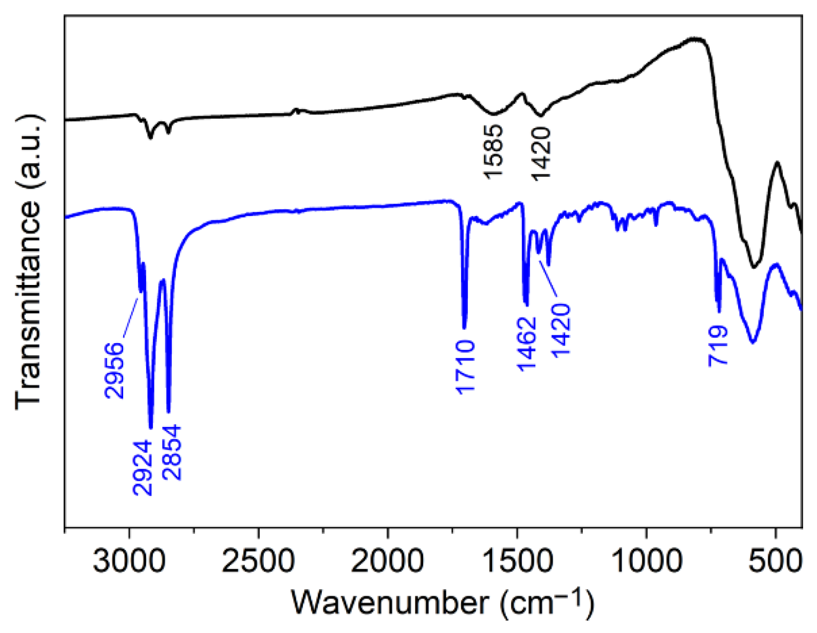
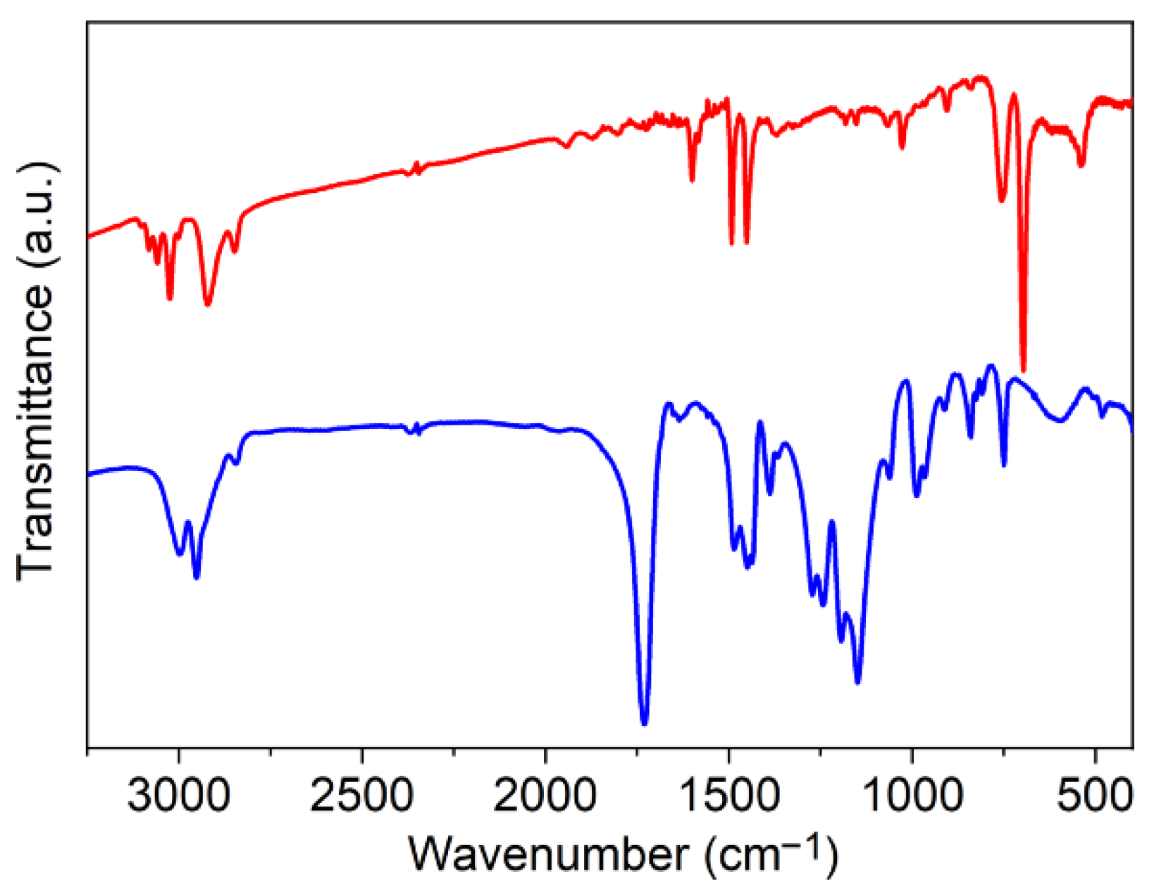
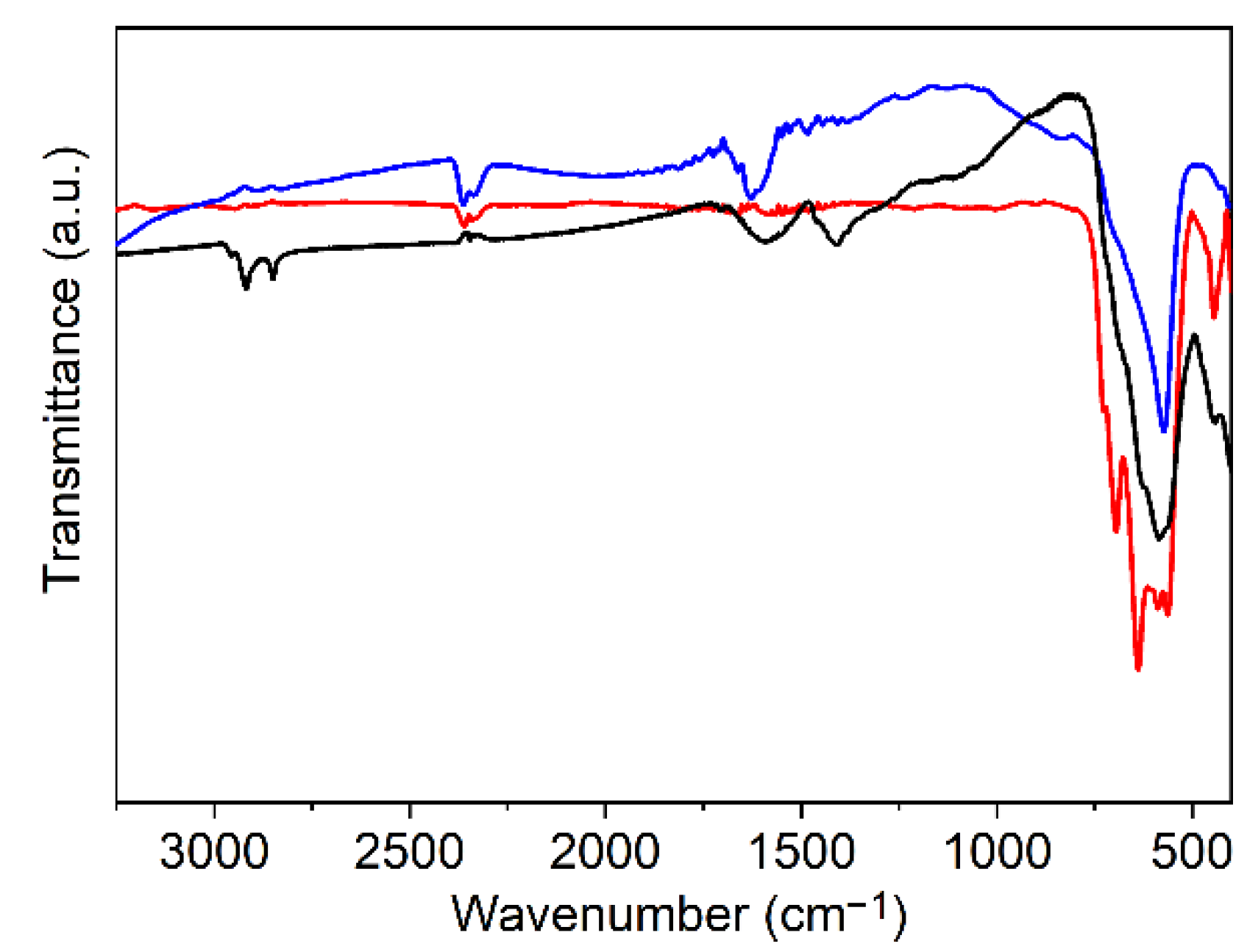
2.3.2. Fourier Transform Infrared (FTIR) Spectroscopy
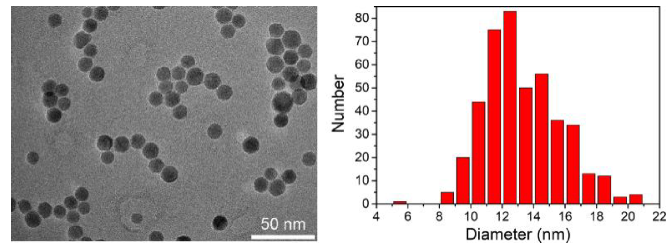
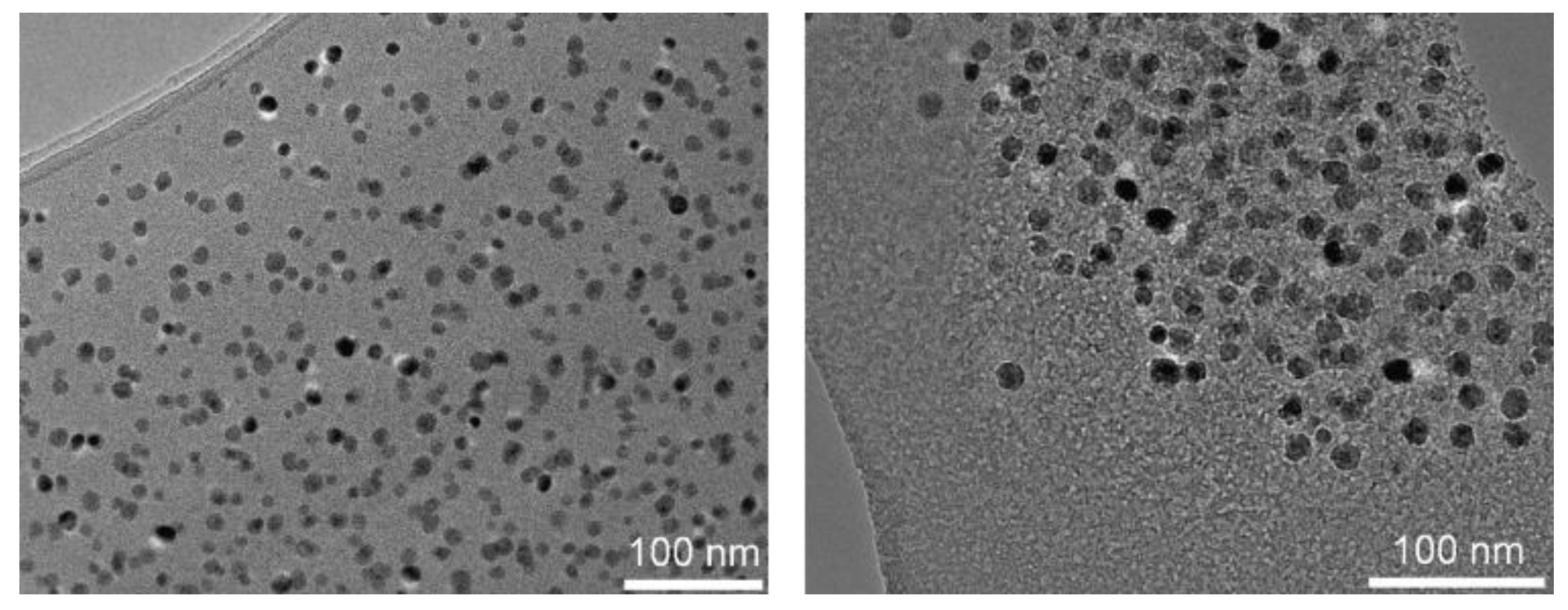
2.3.3. Transmission Electron Microscopy (TEM)
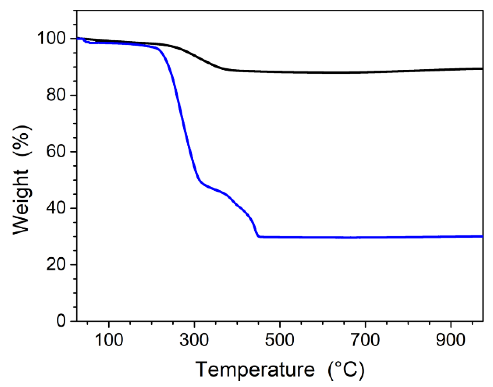
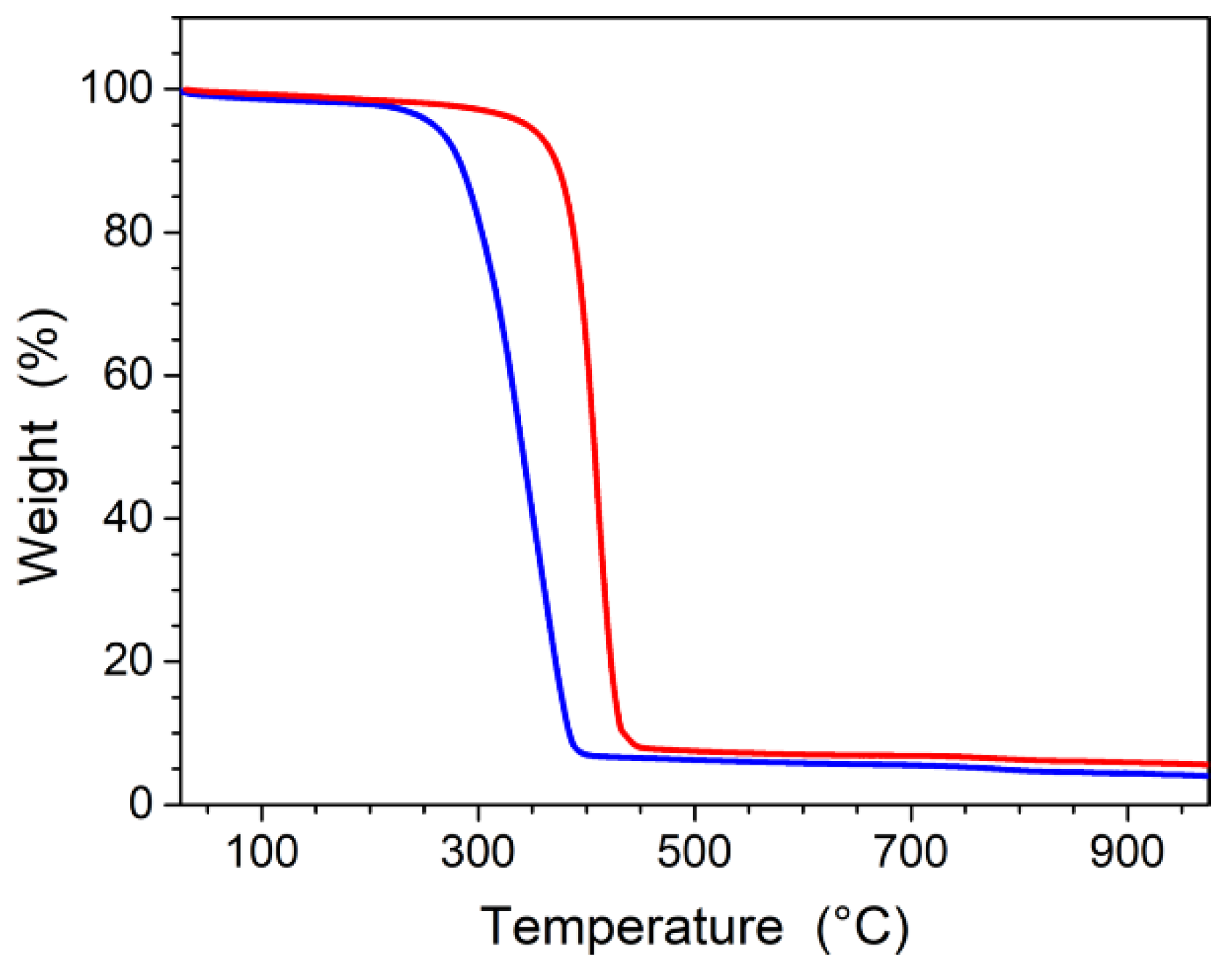
2.3.4. Thermogravimetric Analysis (TGA)
2.3.5. Light Scattering-Size Exclusion Chromatography (LS-SEC)
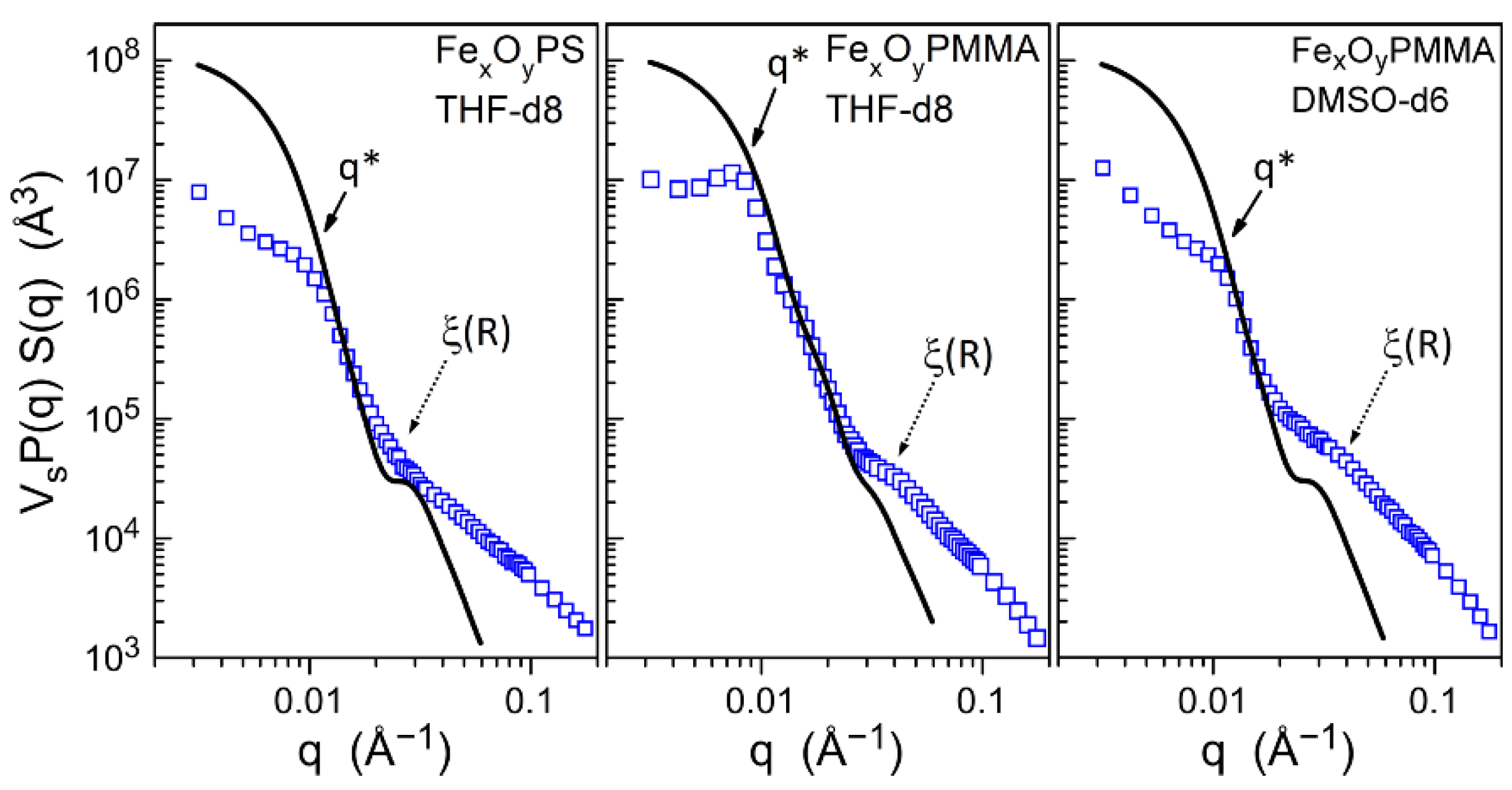
2.3.6. Small-Angle X-ray Scattering (SAXS)
2.3.7. Small-Angle Neutron Scattering (SANS)
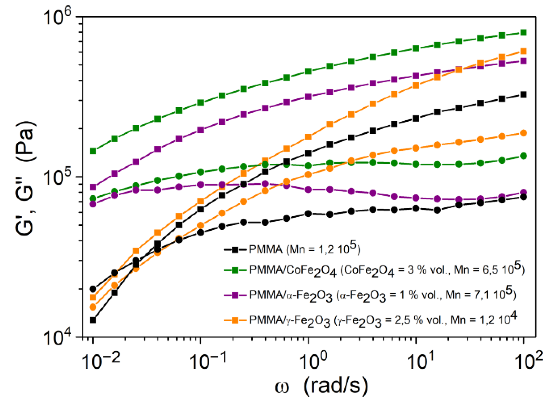
2.3.8. Rheology
2.3.9. ICP-AES
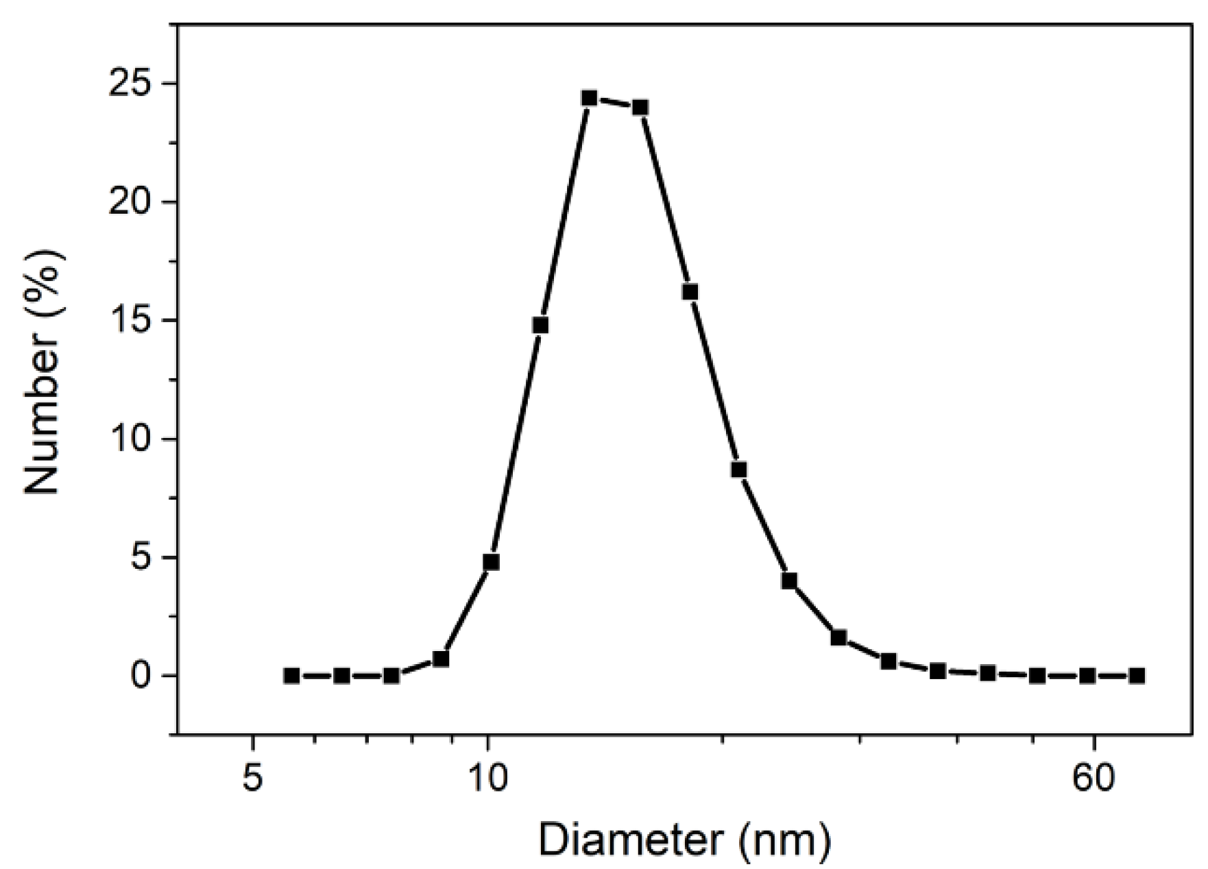
2.3.10. DLS
3. Results
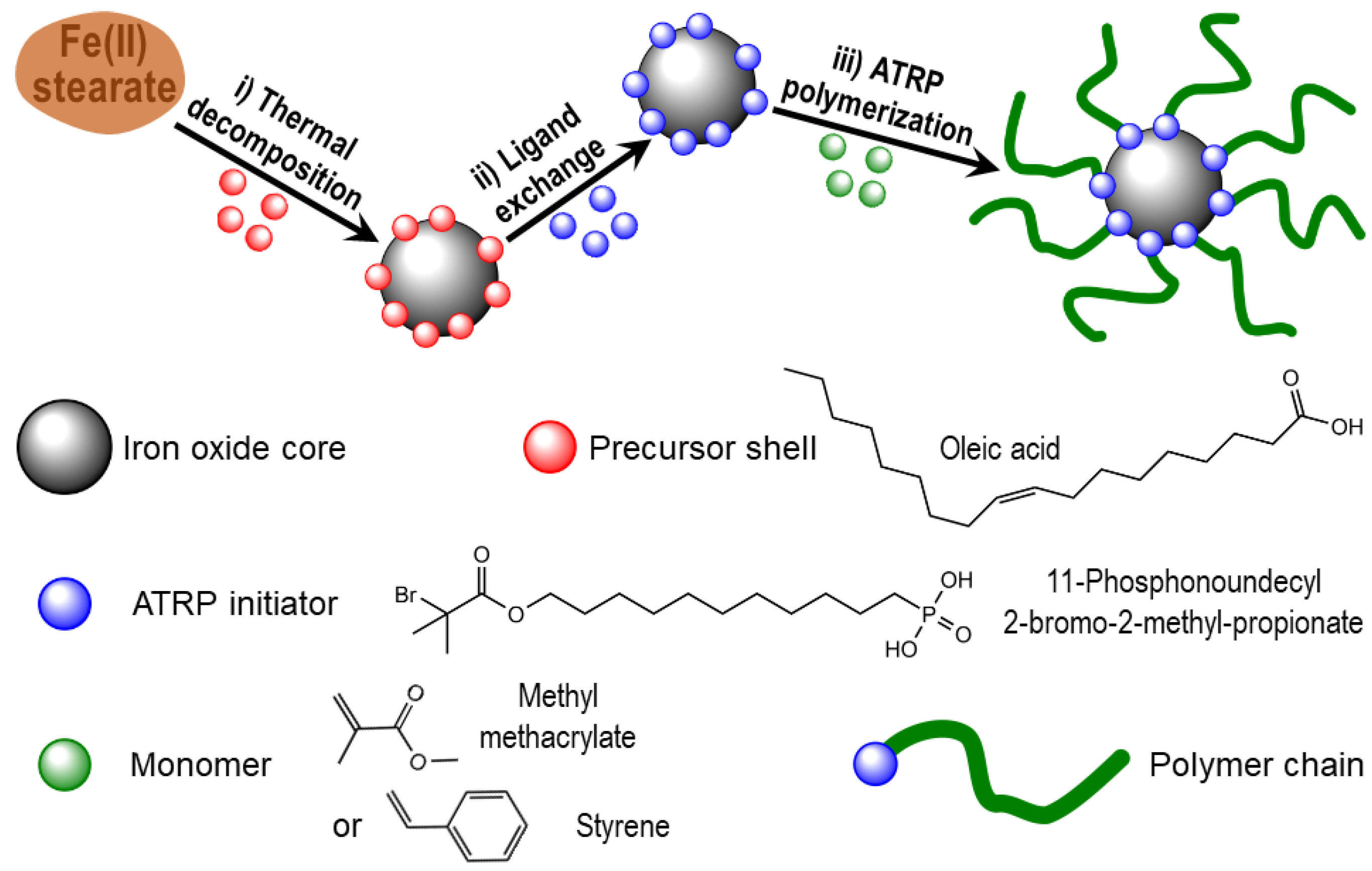
3.1. Elaboration of Core–Shell Iron Oxide–Polystyrene and Iron Oxide–Poly(Methyl Methacrylate)
3.2. Core–Shell Structure and Behavior in Solution of the Hybrid Materials
3.3. Rheological Behavior
4. Discussion
5. Conclusions
Author Contributions
Funding
Institutional Review Board Statement
Informed Consent Statement
Data Availability Statement
Acknowledgments
Conflicts of Interest
Appendix A. Characteristics of Three-Step Route Synthesis
Appendix A.1. Synthesis of Iron Oxide NPs


Appendix A.2. Grafting of Initiator on Iron Oxide Surface

Appendix A.3. Growing of the Polymer Shells


Appendix B. Information and Data from the Combined SAXS and SANS Study

| Molecular Unit | ρ 1 (g/cm3) | V 2 (nm3) | ρe 3 (1010 cm−2) | ρcoh 4 (1010 cm−2) |
|---|---|---|---|---|
| γ-Fe2O3 | 4.860 | 0.0546 | 39.3 | 6.65 |
| PMMA r.u. | 1.19 | 0.140 | 10.8 | 1.06 |
| PS r.u. | 1.04 | 0.166 | 9.59 | 1.41 |
| THF | 0.889 | 0.1347 | 8.37 | 0.18 |
| THF-d8 | 0.985 | 0.1352 | 8.35 | 6.34 |
| DMSO-d6 | 1.184 | 0.1178 | 10.05 | 5.26 |
| Hybrid Material | Mn 1 (g/mol) | VPol 3 (nm3) | DC 5 (nm) | VSh 7 (nm3) | f 9 | f/fmax 11 (%) |
|---|---|---|---|---|---|---|
| ρPol 2 (g/mol) | σPol 4 (nm2) | DCSh 6 (nm) | SC 8 (nm2) | SPol 10 (nm2) | Xvs 12 (%) | |
| PS/γ-Fe2O3 | 297 × 103 | 474 | 13 | 116 × 103 | 244 | 30 |
| 1.04 | 0.655 | 60.6 | 531 | 2.18 | 93 | |
| PMMA/γ-Fe2O3 | 120 × 103 | 167 | 13 | 109 × 103 | 653 | 68 |
| 1.19 | 0.55 | 59.5 | 531 | 0.81 | 83 {92} |
References
- Nicole, L.; Laberty-Robert, C.; Rozes, L.; Sanchez, C. Hybrid materials science: A promised land for the integrative design of multifunctional materials. Nanoscale 2014, 6, 6267–6292. [Google Scholar] [CrossRef]
- Minko, S. Grafting on Solid Surfaces: “Grafting to” and “Grafting from” Methods. In Polymer Surfaces and Interfaces; Springer: Berlin/Heidelberg, Germany, 2008; pp. 215–234. [Google Scholar]
- Matyjaszewski, K.; Xia, J. Atom Transfer Radical Polymerization. Chem. Rev. 2001, 101, 2921–2990. [Google Scholar] [CrossRef]
- Krystosiak, P.; Tomaszewski, W.; Megiel, E. High-density polystyrene-grafted silver nanoparticles and their use in the preparation of nanocomposites with antibacterial properties. J. Colloid Interface Sci. 2017, 498, 9–21. [Google Scholar] [CrossRef]
- Zawada, K.; Tomaszewski, W.; Megiel, E. A smart synthesis of gold/polystyrene core–shell nanohybrids using TEMPO coated nanoparticles. RSC Adv. 2014, 4, 23876–23885. [Google Scholar] [CrossRef]
- Vestal, C.R.; Zhang, Z.J. Atom Transfer Radical Polymerization Synthesis and Magnetic Characterization of MnFe2O4/Polystyrene Core/Shell Nanoparticles. J. Am. Chem. Soc. 2002, 124, 14312–14313. [Google Scholar] [CrossRef] [PubMed]
- Li, G.; Fan, J.; Jiang, R.; Gao, Y. Cross-linking the Linear Polymeric Chains in the ATRP Synthesis of Iron Oxide/Polystyrene Core/Shell Nanoparticles. Chem. Mater. 2004, 16, 1835–1837. [Google Scholar] [CrossRef]
- Marutani, E.; Yamamoto, S.; Ninjbadgar, T.; Tsujii, Y.; Fukuda, T.; Takano, M. Surface-initiated atom transfer radical polymerization of methyl methacrylate on magnetite nanoparticles. Polymer 2004, 45, 2231–2235. [Google Scholar] [CrossRef]
- Babu, K.; Dhamodharan, R. Synthesis of Polymer Grafted Magnetite Nanoparticle with the Highest Grafting Density via Controlled Radical Polymerization. Nanoscale Res. Lett. 2009, 4, 1090–1102. [Google Scholar] [CrossRef] [PubMed] [Green Version]
- Daou, T.J.; Begin-Colin, S.; Greneche, J.-M.; Thomas, F.; Derory, A.; Bernhardt, P.; Legaré, P.; Pourroy, G. Phosphate Adsorption Properties of Magnetite-Based Nanoparticles. Chem. Mater. 2007, 19, 4494–4505. [Google Scholar] [CrossRef]
- Daou, T.J.; Grenèche, J.M.; Pourroy, G.; Buathong, S.; Derory, A.; Ulhaq-Bouillet, C.; Donnio, B.; Guillon, D.; Begin-Colin, S. Coupling Agent Effect on Magnetic Properties of Functionalized Magnetite-Bases Nanoparticles. Chem. Mater. 2008, 20, 5869–5875. [Google Scholar] [CrossRef]
- Matsuno, R.; Yamamoto, K.; Otsuka, H.; Takahara, A. Polystyrene-Grafted Magnetite Nanoparticles Prepared through Surface-Initiated Nitroxyl-Mediated Radical Polymerization. Chem. Mater. 2003, 15, 3–5. [Google Scholar] [CrossRef]
- Matsuno, R.; Yamamoto, K.; Otsuka, H.; Takahara, A. Polystyrene- and Poly(3-vinylpyridine)-Grafted Magnetite Nanoparticles Prepared through Surface-Initiated Nitroxide-Mediated Radical Polymerization. Macromolecules 2004, 37, 2203–2209. [Google Scholar] [CrossRef]
- Ramakrishnan, A.; Dhamodharan, R.; Rühe, J. Controlled Growth of PMMA Brushes on Silicon Surfaces at Room Temperature Macromol. Rapid Commun. 2002, 23, 612–616. [Google Scholar] [CrossRef]
- Babu, K.; Dhamodharan, R. Grafting of Poly(methyl methacrylate) Brushes from Magnetite Nanoparticles Using a Phosphonic Acid Based Initiator by Ambient Temperature Atom Transfer Radical Polymerization (ATATRP). Nanoscale Res. Lett. 2008, 3, 109–117. [Google Scholar] [CrossRef] [Green Version]
- Hyeon, T. Chemical synthesis of magnetic nanoparticles. Chem. Commun. 2003, 927–934. [Google Scholar] [CrossRef] [PubMed]
- Vergnat, V.; Pourroy, G.; Masson, P. Enhancement of styrene conversion in organic/inorganic hybrid materials by using malononitrile in controlled radical polymerization. Polym. Int. 2013, 62, 878–883. [Google Scholar] [CrossRef]
- Maliakal, A.; Katz, H.; Cotts, P.M.; Subramoney, A.S.; Mirau, P. Inorganic Oxide Core, Polymer Shell Nanocomposite as a HighKGate Dielectric for Flexible Electronics Applications. J. Am. Chem. Soc. 2005, 127, 14655–14662. [Google Scholar] [CrossRef]
- Serre, C.; Férey, G. The Cambridge Structural Database. Inorg. Chem. 2001, 40, 5350–5353. [Google Scholar] [CrossRef] [PubMed]
- Pyun, J.; Jia, S.; Kowalewski, T.; Patterson, G.D.; Matyjaszewski, K. Synthesis and Characterization of Organic/Inorganic Hybrid Nanoparticles: Kinetics of Surface-Initiated Atom Transfer Radical Polymerization and Morphology of Hybrid Nanoparticle Ultrathin Films. Macromolecules 2003, 36, 5094–5104. [Google Scholar] [CrossRef]
- Schmidt, R.; Schmutz, M.; Mathis, A.; Decher, G.; Rawiso, M.; Mésini, P.J. New Synthetic Oligoamide Gelators: Structural Study by X-ray and Neutron Scattering. Langmuir 2002, 18, 7167–7173. [Google Scholar] [CrossRef]
- Daoud, M.; Cotton, J.P. Star shaped polymers: A model for the conformation and its concentration dependence. J. Phys. 1982, 43, 531–538. [Google Scholar] [CrossRef]
- Rawiso, M. De l’intensité à la structure en physico-chimie des polymères. J. Phys. IV 1999, 9, Pr1-147. [Google Scholar] [CrossRef] [Green Version]
- Fetters, L.J.; Kiss, A.D.; Pearson, D.S.; Quack, G.F.; Vitus, F.J. Rheological behavior of star-shaped polymers. Macromolecules 1993, 26, 647–654. [Google Scholar] [CrossRef]
- Ball, R.C.; McLeish, T. Dynamic dilution and the viscosity of star-polymer melts. Macromolecules 1989, 22, 1911–1913. [Google Scholar] [CrossRef]
- Wu, L.; Glebe, U.; Böker, A. Surface-initiated controlled radical polymerizations from silica nanoparticles, gold nanocrystals, and bionanoparticles. Polym. Chem. 2015, 6, 5143–5184. [Google Scholar] [CrossRef] [Green Version]
- Dozier, W.D.; Huang, J.S.; Fetters, L.J. Colloidal nature of star polymer dilute and semidilute solutions. Macromolecules 1991, 24, 2810–2814. [Google Scholar] [CrossRef]
- Richter, D.; Jucknischke, O.; Willner, L.; Fetters, L.J.; Lin, M.; Huang, J.S.; Roovers, J.; Toporovski, C.; Zhou, L.L. Scaling properties and ordering phenomena of star polymers in solution. J. Phys. IV Fr. 1993, C8, 3–12. [Google Scholar] [CrossRef]
- Hore, M.J.A.; Ford, J.; Ohno, K.; Composto, R.J.; Hammouda, B. Direct Measurements of Polymer Brush Conformation Using Small-Angle Neutron Scattering (SANS) from Highly Grafted Iron Oxide Nanoparticles in Homopolymer Melts. Macromolecules 2013, 46, 9341–9348. [Google Scholar] [CrossRef]
- Grillo, I. Small-angle neutron scattering and applications in soft condensed matter. In Soft-Matter Characterization; Borsali, R., Pecora, R., Eds.; Springer: Dordrecht, The Netherlands, 2008; pp. 707–727. [Google Scholar]


| Hybrid Material | Converted Monomer (%) | Mn (Da) | Mw/Mn | Initiator Efficiency (%) |
|---|---|---|---|---|
| PS/γ-Fe2O3 | 45 | 30 × 104 | 1.23 | 14 |
| PMMA/γ-Fe2O3 | 62 | 12 × 104 | 1.52 | 38 |
Publisher’s Note: MDPI stays neutral with regard to jurisdictional claims in published maps and institutional affiliations. |
© 2021 by the authors. Licensee MDPI, Basel, Switzerland. This article is an open access article distributed under the terms and conditions of the Creative Commons Attribution (CC BY) license (https://creativecommons.org/licenses/by/4.0/).
Share and Cite
Vergnat, V.; Heinrich, B.; Rawiso, M.; Muller, R.; Pourroy, G.; Masson, P. Iron Oxide/Polymer Core–Shell Nanomaterials with Star-like Behavior. Nanomaterials 2021, 11, 2453. https://doi.org/10.3390/nano11092453
Vergnat V, Heinrich B, Rawiso M, Muller R, Pourroy G, Masson P. Iron Oxide/Polymer Core–Shell Nanomaterials with Star-like Behavior. Nanomaterials. 2021; 11(9):2453. https://doi.org/10.3390/nano11092453
Chicago/Turabian StyleVergnat, Virginie, Benoît Heinrich, Michel Rawiso, René Muller, Geneviève Pourroy, and Patrick Masson. 2021. "Iron Oxide/Polymer Core–Shell Nanomaterials with Star-like Behavior" Nanomaterials 11, no. 9: 2453. https://doi.org/10.3390/nano11092453