Review

Carbon-Based Nanofluids and Their Advances towards Heat Transfer Applications—A Review

1
Nanotechnology and Advanced Materials Program, Energy and Building Research Center, Kuwait Institute for Scientific Research, Safat 13109, Kuwait
2
Mechanical Engineering Department, College of Engineering and Petroleum, Kuwait University, P.O. Box 5969, Safat 13060, Kuwait
3
Thermal Research Laboratory (TRL), School of Mechanical Engineering, Kalinga Institute of Industrial Technology, Bhubaneswar, Odisha 751024, India
4
School of Aerospace, Transport and Manufacturing (SATM), Cranfield University, Cranfield MK43 0AL, UK
*
Author to whom correspondence should be addressed.
Nanomaterials 2021, 11(6), 1628; https://doi.org/10.3390/nano11061628
Submission received: 26 May 2021 / Revised: 16 June 2021 / Accepted: 17 June 2021 / Published: 21 June 2021
(This article belongs to the Special Issue Heat Transfer and Fluids Properties of Nanofluids)

Abstract

:
Nanofluids have opened the doors towards the enhancement of many of today’s existing thermal applications performance. This is because these advanced working fluids exhibit exceptional thermophysical properties, and thus making them excellent candidates for replacing conventional working fluids. On the other hand, nanomaterials of carbon-base were proven throughout the literature to have the highest thermal conductivity among all other types of nanoscaled materials. Therefore, when these materials are homogeneously dispersed in a base fluid, the resulting suspension will theoretically attain orders of magnitude higher effective thermal conductivity than its counterpart. Despite this fact, there are still some challenges that are associated with these types of fluids. The main obstacle is the dispersion stability of the nanomaterials, which can lead the attractive properties of the nanofluid to degrade with time, up to the point where they lose their effectiveness. For such reason, this work has been devoted towards providing a systematic review on nanofluids of carbon-base, precisely; carbon nanotubes, graphene, and nanodiamonds, and their employment in thermal systems commonly used in the energy sectors. Firstly, this work reviews the synthesis approaches of the carbon-based feedstock. Then, it explains the different nanofluids fabrication methods. The dispersion stability is also discussed in terms of measuring techniques, enhancement methods, and its effect on the suspension thermophysical properties. The study summarizes the development in the correlations used to predict the thermophysical properties of the dispersion. Furthermore, it assesses the influence of these advanced working fluids on parabolic trough solar collectors, nuclear reactor systems, and air conditioning and refrigeration systems. Lastly, the current gap in scientific knowledge is provided to set up future research directions.

Graphical Abstract

1. Introduction

Since the 20th century, scientists have been working with considerable effort to develop fluids that can surpass those conventionally known by the scientific society and industry in terms of thermal and physical performance. The idea of dispersing solid particles of millimeter (mm) and micrometer (µm) in size is the milestone, which was physically initiated by Ahuja [1,2] in 1975, Liu et al. [3] in 1988, and other researchers at Argonne National Laboratory (ANL) [4,5,6] in 1992 on the bases of Maxwell theoretical work [7]. Such suspensions have shown tremendous improvements in heat transfer characteristics compared to their base fluids. This is due to the dispersed solid particles’ significantly higher thermal conductivity compared to their hosting fluid, which would enhance the effective thermal conductivity of the colloidal. The term ‘effective’ is generally used when referring to the net property of a solid–liquid suspension [8]. However, it was found that in flow areas of low velocities, the particles hosted by the suspension tended to deposit from its carrier liquid. Additionally, hence the fluid starts to lose its tuned properties. Furthermore, clogging of small passages was also experienced due to the significant level of agglomeration between the dispersed particles, and therefore making it extremely challenging to employ in heat transfer devices containing small channels. This is when, in 1993, Masuda et al. [9] conceived the idea of fabricating suspensions with ultrafine particles of silica, alumina, and titanium dioxide, where these dispersions were afterward given the name ‘Nanofluids’ by Choi and Eastman [10], in 1995, as a result of their extensive research work at ANL. According to the founders, a nanofluid can be generally defined as an advanced category of fluid that is produced by homogeneously dispersing low concentrations (preferably ≤1 vol. %) of particles of less than 100 nanometers (nm) in size within a non-dissolving base fluid [11]. Both Masuda et al.’s [9] and Choi and Eastman’s [10] primary motivation at that time was to overcome the limitations associated with suspensions made by their counterparts (i.e., colloidal containing millimeter or micrometer sized particles). In addition, Choi and Eastman [10] have theoretically known beforehand that reducing the size of the dispersed particles to the nanoscale would greatly enlarge the particle exposed surface area to the surrounding, and thus increasing the suspension overall thermal conductivity [12]. The significant variation in thermal conductivity between solid particles and liquids can be clearly seen in Figure 1 for some of the most commonly used particles and base fluids, at room temperature and atmospheric pressure, for fabricating nanofluids [13,14,15,16,17]. It is worth noticing that CuO, MgO, Al2O3, ZnO, TiO2, Fe2O3, SiO2, Ag, Cu, Au, Al, Fe, carbon nanotubes (CNTs), and multiwalled carbon nanotubes (MWCNTs) stands for cupric oxide, magnesium oxide, aluminum oxide, zinc oxide, titanium dioxide, iron(III) oxide, silicon dioxide, silver, copper, gold, aluminum, iron, carbon nanotubes, and multiwalled carbon nanotubes, respectively. Furthermore, the thermal conductivity of some of the materials shown in Figure 1 was seen to have a significant scatter of data across the literature, which can be linked to several factors such as the purity, crystallinity, particle size, and the determination approach used to find this thermal property. In addition, the thermal conductivity of graphene after being subjected to oxidization (i.e., having the form of graphene oxide) gets highly reduced, where it can reach values between 1000 and 2 W/m·K [18,19,20].
Following their success, many researchers started to explore and develop this class of engineered fluid via modifying their production route, enhancing the suspension stability, and improving the colloidal thermal conductivity [13,21,22]. As of today, nanofluids are seen to have potential usage in a wide range of areas, including the energy sector, construction and building, transportation, oil and gas, medical sector, etc. [23,24,25,26,27,28,29,30,31,32,33,34]. Figure 2a shows the increasing trend in scientific publications in the field of nanofluids from 1995 to 2020, while Figure 2b illustrates the different types of these published documents that are available in the same database. It is worth mentioning that the data in Figure 2 was obtained from Elsevier’s abstract and citation database, Scopus, via searching through the word ‘Nanofluid’ [35].
Despite the promising achievements that nanofluids could deliver to the scientific community, there are still some obstacles that need to be overcome before this category of fluids can be industrially accepted. For example, the colloidal preparation phase is still considered one of the most significant challenges, as this stage can strongly influence the fluid physical stability and effective thermophysical properties [13,36]. Meaning that if the fabrication process used was not well structured before being executed, the chances of an unstable nanofluid being produced is likely to occur. As a result, some of the suspension’s thermophysical properties will gradually degrade with time due to the separation of particles from the hosting base fluid. Almurtaji et al. [37] have illustrated in their published work the relationship between the effective thermal conductivity and the physical stability of suspensions. They showed that the effective thermal conductivity of a nanofluid could reach its optimum possible value when the dispersion is physically stable, and vice versa. In addition, the commonly employed two-step fabrication method that relies on an ultrasonic bath type device, was reported to raise the as-prepared nanofluid temperature and that the surrounding atmospheric conditions govern this increase in temperature along with the sonicator working power. Thus, it is highly unlikely that similar nanofluids can be produced through the conventional two-step route without simultaneously fabricating the products at the same preparation conditions. A more convenient two-step method employed for nanofluid production would be the two-step controlled sonicator bath temperature approach, as was reported by Ali et al. [8,11] and Song et al. [38]. The aforementioned approach would eliminate the rise in bath temperature obstacle, and hence will ensure an optimum level of nanofluids reproducibility to the manufacturer at any surrounding atmospheric conditions, and even when using different types of bath sonicators. Furthermore, as the thermal properties of a nanofluid are influenced mainly by the dispersed particles compared to its base fluid, researchers have been focusing more on carbon-based materials. This is because some of these materials, in the nanoscale, have exceptional thermophysical properties compared to other commonly used materials (e.g., metals and oxides) [39,40,41]. For instance, CNTs and graphene have significantly elevated thermal conductivity [42,43], large aspect ratio [44], lower density [45,46], lower erosion and corrosion surface effects [47], higher stability [43], and lower pressure drop and pumping power requirement in comparison to other types of nanomaterials [48,49]. Figure 3 demonstrates common allotropes of carbon nanomaterials.
Many published numerical and experimental studies on nanofluids fabricated with particles of carbon-based materials were found in the literature, which show the continued growth of interest in such materials [35,51,52,53,54]. Figure 4 classifies these documents in terms of the number of available publications at the Scopus database for each type of carbon-based material used in nanofluids production. The single-walled carbon nanotube (SWCNT) and double-walled carbon nanotube (DWCNT) abbreviations in Figure 4 refer to the single-walled carbon nanotube and double-walled carbon nanotube, respectively. During the reviewing process, which led to the formation of Figure 4, the authors remarkably recognized that the researchers had used different sonication duration and intensities to fabricate their nanofluids. However, some of the suspensions had the same particles type, size, and hosting base fluid. This shows that, up to today, there is no standard fabrication method for the production of the colloidal. The authors have also found that dispersing carbon-based materials, such as walled carbon nanotubes (MCNTs) and graphene, can tremendously enhance the quality of biofuels blends, in specific biodiesel [55,56]. This includes lowering the brake specific fuel consumption, stabilizing the fuel consumption rate and brake thermal efficiency, and improving the diesel engine performance and the resulting emissions from the combustion process.
This review paper provides an overview of three types of carbon-based nanofluids: CNT, nanodiamond (ND), and graphene. The selection reason for these three carbon-based particles is due to their outstanding thermal properties compared to any other sort of nanoscaled solids. Hence, they can be considered promising candidates for fabricating nanofluids targeted towards heat transfer applications. The main contribution of the present review study is that this work starts from the synthesis stage of these three carbon-based materials, followed by their dispersed form, and up to their employment in selected energy applications. Furthermore, recommendations on the different nanofluids production methods used are shown along with the colloidal stability and its effect on the thermophysical properties. Moreover, the experimental measuring devices and theoretical equations used to determine and predict the thermophysical properties are provided. In addition, the research work done on utilizing these carbon-based suspensions are presented for three thermal applications, namely, parabolic trough solar collectors (PTSCs), nuclear reactors, and air conditioning and refrigeration (AC&R) systems, with a comparison to those of conventional working fluids. Finally, the gaps in present scientific knowledge that scientists need to tackle are highlighted in order to promote these advanced types of heat transfer fluids commercially.

2. Synthesis of Nanoscaled Carbon-Based Materials

Carbon ranks as the 4th most common element after hydrogen, helium, and oxygen in our solar system, and the 17th in the crust of our planet [57]. Remarkably, this element is distinctive so that when the crystal structure of carbon atoms is changed into deferent arrangements, the material properties significantly differ [58,59,60,61,62,63]. For example, both ND and graphene are made of carbon but of different atomic bounds arrangement. While the first is an electrical isolator and transparent towards visible light waves, the second has excellent electrical conductivity with complete visible light blockage. Such materials that contain various arrangements of carbon atoms are known as ‘allotropes of carbon’, which means that the material has chemically identical elements but with different atomic arrangements, and hence different physical properties. Due to this fact, many allotropes of carbon exist or have been discovered by scientists, e.g., diamond, graphene, and CNTs. The following Section 2.1, Section 2.2 and Section 2.3. will provide a short overview of the fabrication of three allotropes of carbon in the nanoscale, namely ND, graphene, and CNTs. Knowing the production methods of these materials is essential and will, later on, help us understand which nanofluid fabrication route is suitable to conduct.

2.1. Nanodiamonds

NDs have existed for billions of years in nature within meteorites, crude oil, interstellar dust protoplanetary nebulae, and different sediment layers of the Earth’s crust. Nevertheless, the synthetization process of this valuable material only started in the second half of the nineteenth century through either exposing graphite to high pressure and high temperature conditions, or by the explosive detonation of bulk graphite [64,65,66]. The first is known as the high-pressure and high-temperature (HPHT) approach, whereas the second route is known as the detonation technique. In the literature, it was reported that the first study conducted on the preparation of NDs was performed by Bovenkerk et al. [67], in 1959, after which Danilenko [68] used the detonation technique as part of his synthesis approach. Furthermore, many approaches were developed afterward for fabricating ND, such as the microplasma-assisted formation [69], chemical vapor deposition (CVD) method [70], laser ablation [71], high energy ball milling of microdiamonds produced from high pressure and high temperature conditions [72], high energy ball milling of ultra-fine graphite powder [73,74], ultrasound cavitation [75], chlorination of carbides [76], carbon onions irradiated by electron [77], and irradiation of graphite by ion beam [78]. In addition to the previous synthesizing methods, El-Eskandarany has proposed a novel approach for producing superfine NDs from commercial graphite powders and SWCNTs under ambient temperature and atmospheric pressure conditions, using a high-energy ball mill technique [79]. It is important to note that, according to Ali et al. [66] and Mochalin et al. [80], the most common types of NDs seen today are the detonation NDs (DNDs) and the HPHT-NDs. From the aforementioned production routes, it can be concluded that the synthesized NDs can only be produced as independent solid particles, and therefore cannot be grown within liquids through chemical and/or physical approaches. Regardless of the method used, the production of NDs usually involves three major phases, which are 1—synthesis (methods mentioned earlier), 2—processing, and 3—modification. The processing stage, which follows the synthesis phase, enhances the as-produced NDs purity by removing the metals and metals oxides along with the non-diamond carbons that remain attached to the ND surface. Hence, a high level of sp3 carbon bonded diamond nanoparticles can be obtained. This can be done by using oxidants such as nitric acid (HNO3), perchloric acid (HCLO4), or hydrochloric acid (HCL) [81]. Furthermore, the modification phase is essential so that the fabricated NDs can meet the requirements of their targeted application. Modification can be performed using either surface functionalization (widely used) or doping of the NDs particles. It is important to note that some researchers have recently started focusing on the doping technique due to the distinct optical properties gained from this NDs modification approach [82,83]. Figure 5 shows the three phases involved in the production of NDs [84].

2.2. Graphene

Graphene is a type of carbon material that originates from bulk graphite. It has the shape of a 2-dimensional (2D) (i.e., monolayer) sheet of one-atom thickness and lattice of hexagonally arranged sp2 bonded carbon atoms [85]. The material itself was successfully synthesized for the first time in 2004 by Novoselov et al. [86], through mechanical exfoliating graphite with Scotch tape. Furthermore, the development in the field has resulted in categorizing graphene by the materials architecture structure, which ranges from zero-dimensional (0D) graphene quantum dots, one-dimensional (1D) graphene fibers and nanoribbons, and 2D graphene nanomesh, rippled/wrinkled and multisheet [87]. Figure 6 shows an illustration of the different categories of graphene based on their dimensionality and bandgap opening. Regarding 2D graphene sheets, few suitable techniques are commonly employed for producing such material, which are mechanical exfoliation [86], sublimation of silicon carbide (SiC) [88], laser-induced graphene [89,90], covalent [91,92] or non-covalent [93] exfoliation of graphite in liquids, and CVD growth [94]. These fabrication methods produce graphene in a solid form except for the liquid-phase exfoliation, which delivers the material as part of a suspension.
The mechanical exfoliation method was the first approach for obtaining graphene. In this method, the small mesas of highly oriented pyrolytic graphite are repeatedly peeled out with a Scotch tape, and hence the attached thin films on the tape are of monolayer graphene. This production route is highly reliable and allowed the preparation of high-quality graphene sheets of up to 100 µm in thickness [86]. Other less common types of mechanical exfoliation are also available, such as ball milling of graphite nanoparticles [95] and hammering graphite [96]. Furthermore, the high temperature sublimation of SiC, which was developed initially for the electronics industry, relies on the thermal decomposition of a SiC substrate via either an electron beam or resistive heating to epitaxial graphene under ultrahigh vacuum condition. This results in the desorption of the silicon (Si) on the wafer surface, and therefore causing the surface atoms to arrange into forming hexagonal lattice. Moreover, fabricating graphene through laser-inducement is performed under ambient atmosphere by subjecting carbon dioxide (CO2) pulsed laser to a substrate containing carbon-based materials. This approach combines 3-dimensional (3D) graphene fabrication and patterning into a single step without having to use wet chemical steps. In addition, exfoliation of graphite in liquids or liquid-phase exfoliation depends on the employment of external peeling force, such as an ultrasonic horn sonicator, to separate the graphene sheets from the immersed bulk graphite in a solvent of suitable surface tension. The solvent used in the process is usually a non-aqueous solution, such as N-methyl-2-pyrrolidone (NMP), but aqueous solutions can also be employed if surfactant was added. It is important to note that the yield of the liquid-phase exfoliation process is relatively low, and thus centrifugation is used to gain a significant fraction of monolayer and few-layer graphene flakes in the final dispersion [97]. On the other hand, the CVD production route uses hydrocarbon gases to grow graphene on a targeted substrate by carbon diffusion and segregation of high carbon solubility metallic substrates, such as nickel (Ni), or by surface adsorption of low carbon solubility metals (e.g., Cu) [98,99]. From all of the previous methods, CVD has shown to be the most successful, promising, and feasible approach in the field for producing monolayer graphene of high quality and large area [94]. For deeper insight into the various graphene synthesis methods, the reader is referred to the published work of Rao et al. [100].

2.3. Carbon Nanotubes

Although carbon is known as a ubiquitous material in nature, CNTs are not, where this allotrope material is a human-made seamless cylindrical form of carbon. It is believed that the oldest CNTs existed on damascene swords [101]. Still, their first proof of presence was in 1952 through the transmission electron microscopy (TEM) images published by Radushkevich and Lukyanovich [102], after which Boehm [103] and Oberlin et al. [104] obtained similar images along with describing the currently widely accepted CNTs growth model. Conceptually, CNTs are graphene sheets rolled into cylindrical tubes, of less than 1 nm in diameter, with a half fullerenes caped end. Based on the number of consistent tubes (i.e., rolled-up graphene sheets), CNTs can be classified as SWCNTs, DWCNTs, and MWCNTs. As the terms suggest, the SWCNTs consist of only one tube, whereas DWCNTs and MWCNTs comprise two and three (or more) tubes, respectively [105,106]. Figure 7 shows the mechanism in which CNTs are formed and their three different types. It is important to note that some researchers distinguished between the three tubes form of CNTs and those of a higher number of tubes, where they have categorized the first as the triple-walled carbon nanotubes (TWCNTs) and the second as MWCNTs [107,108].
There are three main synthesis methods for producing CNTs, which are the arc discharge, laser ablation, and CVD [109,110,111]. Other approaches, such as diffusion and premised flame method, can be used for CNTs fabrication but are less frequently utilized [112]. All three primary production methods depend on the carbon feedstock, either as a solid phased carbon source (arc discharge and laser ablation) or carbonaceous gases (CVD method). An example of the gases employed in the CVD process include carbon monoxide (CO), ethanol, and acetylene. Moreover, the final product is always delivered in a dried form; thus, CNTs cannot be grown within liquids as dispersions. In the arc discharge process, doped graphite rods or two catalysts loaded are vaporized at 4000–5000 K, within a closed chamber, by an electric arc placed between them, after which the resulting deposit is of CNTs. Like the arc discharge method, the laser ablation route relies on the evaporation of a carbon feedstock, usually a graphite rod with a metallic based catalyst, to obtain the CNTs. The difference between this approach and the previous one is that the laser ablation uses high energy laser irradiation to heat the carbon source, and thus causing the phase transformation (i.e., from the solid to gaseous phase). Additionally, the final product gets accumulated in a cold trap located within the chamber. Therefore, this technique is much more efficient than the arc discharge process in terms of the losses in the as-produced CNTs. On the other hand, the CVD, which was mentioned earlier in Section 2.2, decomposes carbonaceous gases on catalytic nanoparticles to produce the CNTs. The catalytic nanoparticles used for this purpose are either grown while conducting the process or are initially fabricated through a separate procedure. Furthermore, the advantage associated with this production technique is the high level of control over the synthesis process parameters such as carbon supply rate, growth temperature, catalyst particles size, and type of substrate used for the CNTs growth.

3. Preparation of Nanofluids

Nanofluids can be formed by dispersion particles made of single elements (e.g., Cu and Fe), single element oxides (e.g., CuO and Al2O3), alloys (e.g., stainless steel), metal carbides (e.g., silicon carbide and zirconium carbide), metal nitrides (e.g., silicon nitride and titanium nitride), or carbon-based materials in a none dissolving base fluid such as water, methanol, glycol, ethylene glycol (EG), transformer oil, kerosene, and/or different types of refrigerants with or without the use of surfactant/s [13,113]. The nanosuspension is given the name ‘nanofluid’ when one type of nanoparticles is used in the fabrication process; in contrast to the previous category, dispersions formed by employing two or more types of nanoparticles are classified as ‘hybrid nanofluids’ [114,115]. To the best of the authors knowledge, unlike the previous two nanofluids categories that are subjected to the number of different particles used in the process, there does not exist a specific classification for nanofluids made of more than one type of base fluid. However, researchers could have used the terms ‘Bi-liquid nanofluid’ or ‘Tri-liquid nanofluid’ to refer to their nanofluid that is made from two or three base fluids, respectively. Figure 8 shows an illustration of the conventional nanofluid and the hybrid nanofluid. In addition, the homogeneity and physical stability of the dispersion depend significantly on the implemented preparation approach, which can substantially influence the effective thermophysical properties of the as-prepared suspension. Knowing the aforementioned is essential when selecting the appropriate type of nanofluid for any targeted application [116]. In general, two known fabrication processes are currently used for producing nanofluids, namely, the one-step (also referred to as the single-step) method and the two-step approach [37]. It is important to note that some researchers prefer to classify the one-step production processes into two categories, which are the one-step physical technique and the one-step chemical approach, resulting in three types of methods of nanofluid fabrication for these groups [117,118]. A summary of the two fabrication schemes (i.e., the one-step and two-step methods) is presented in the following subsections.

3.1. One-Step Method

The production of nanofluids by the one-step method is conducted by simultaneous synthesizing and dispersing the nanoparticles in the base fluid. Thus, the storage, drying, and transportation of nanoparticles are unnecessary [119]. Furthermore, the dispersed particles in this bottom-up process avoid oxidization from their surrounding environment. In addition, this technique is well known to highly eliminate clustering and agglomeration of dispersed particles within the hosting fluid, and hence coagulation of nanoparticles in real-life applications that uses microchannels can be minimized with an increase in the level of the physical stability of the colloidal compared to the two-step production approach. Moreover, this method allows greater control over the size and shape of the dispersed nanoparticles during the fabrication process. Nevertheless, the presence of residual reactants as a result of uncompleted reactions has always been a major drawback of such a production route. Other disadvantages can also be experienced when following the single-step synthesis approach, such as the inconsistency of the scale for industrial applications, which can only be used with base liquids of low pressure, high production cost, and limitation in the types of nanofluids that can be fabricated compared to the two-step route [120,121,122,123].
One of the most common one-step approaches is the one that was established by Eastman et al. [21]. In this method, nanofluids are synthesized by evaporating a bulk material, after which the evaporated particles get deposited then condensed in a thin film of base fluid attached to a vessel wall due to centrifugation. Figure 9 demonstrates the aforementioned one-step approach. Many researchers have continuously worked on developing the one-step fabrication approach through physical and/or chemical means. Today, different methods have been acknowledged to be in the one-step nanofluid production category [36,120,124]. Figure 10 shows some of the commonly known one-step nanofluid fabrication routes in the field where their method of conduct can be found fully explained in the published work of Ali et al. [13] and Mukherjee et al. [36].

3.2. Two-Step Method

Unlike the one-step method, the two-step approach is a top-down process that uses dried nanoparticles that were initially prepared, through physical or chemical processes, after which these particles get dispersed in a base fluid through ultrasonic agitation [125,126,127,128], magnetic stirring [129,130,131,132], homogenizing [131,133,134], or ball milling (least commonly used) [16,135,136] with or without adding surfactant(s) to the mixture. Other less common dispersion routes can also be used, such as dissolver, kneader, three roller mill, stirred media mill, and disc mill [137]. Figure 11 demonstrates an example of the two-step method, where a bath type ultrasonic device is used to form the suspension. In addition to the bath type sonicators, some researchers have employed the probe/horn type sonicators to fabricate their nanofluids. They have reported higher particles dispersion capability and enhanced suspensions thermal properties using this type of device compared to the bath type dispersers [138]. The reason behind the previously achieved improvements in the suspension is that the probe device provides focused and intense ultrasonication effects, reaching up to 20 kW/L, to the mixture in an evenly distributed manner [139]. This is something that the bath type sonicators cannot provide due to its low relative intensity (i.e., 20–40 W/L) and non-uniform distribution of the ultrasonication effect on the fabricated nanofluid. It is important to note that the bath type ultrasonicator is more applicable for commercial scale production of nanofluids. In contrast, the probe type is better suited for synthesis at the lab scale. Regardless of the type of two-step mixing approach used, this method is still considered as a cost-effective process that is appropriate for both small- and large-scale production of any type of nanofluids, which is seen as a favorable approach to many researchers in the field [140]. However, some of the critical issues associated with this method during nanofluids fabrication are the agglomeration of the nanoparticles due to the very high surface energy between the particles, and the notable increase in the process temperature with fabrication time when using some of the mixing devices (e.g., bath type ultrasonic device) [8,13]. The first obstacle causes the suspension to be in a weak physical stability state that results from the nanoparticles undergoing agglomeration, which is followed by separation of the particles from the base fluid in the form of sediments. Thus, the nanofluid thermophysical properties degrade with time. As for the raise in fabrication process temperature problem, the reproducibility of similar nanofluids (i.e., obtaining suspensions with the same thermophysical properties) would be impossible to achieve. This is because different bath type ultrasonic devices and/or surrounding atmospheric conditions lead to varying the thermophysical properties and physical stability of the fabricated colloidal [8,38]. There are several ways to overcome the aforementioned limitations in the two-step method. For example, surfactants can be added to the mixture to reduce the level of particles agglomeration, and the sonicator bath temperature could be controlled throughout the fabrication process by equipping the device with a temperature regulator. Other approaches used to physically stabilize the as-prepared dispersions are mentioned afterward in the nanofluid stability enhancement section (Section 4.2). When preparing nanofluids, the nanoparticles and surfactants (if required) are added to the base fluid with respect to either volume (vol.) or weight (wt.) percentage (%). Most researchers tend to use the vol. % to calculate the added nanopowder to the base fluid, which can be estimated through the appropriate formulae presented in Table 1.
Where V , m , ρ , n p , n p 1 , n p 2 , b f , b f 1 , and b f 2 represent the volume, mass, density, single type of nanoparticles, first type of nanoparticles, second type of nanoparticles, single type of base fluid, first type of base fluid, and second type of base fluid, respectively. In addition to the equations shown in Table 1, one can use the following three equations to determine the vol. % for their nanofluids when having two different particles and/or two base fluids concentration ratio(s).
For single type of nanoparticles and two different types of base fluids:
( m ρ ) n p   ( m ρ ) n p + [ ( m ρ ) b f 1 × A A + B + ( m ρ ) b f 2 × B A + B ]   × 100
where the ratio of b f 1 : b f 2 is equal to A : B .
For two different types of nanoparticles and single type of base fluid:
( m ρ ) n p 1 × A A + B + ( m ρ ) n p 2 × B A + B   [ ( m ρ ) n p 1 × C C + D + ( m ρ ) n p 2 × D C + D ] + ( m ρ ) b f × 100
where the ratio of n p 1 : n p 2 is equal to C : D .
For two different types of nanoparticles and two types of base fluid:
( m ρ ) n p 1 + ( m ρ ) n p 2   [ ( m ρ ) n p 1 × C C + D + ( m ρ ) n p 2 × D C + D ] + [ ( m ρ ) b f 1 × A A + B + ( m ρ ) b f 2 × B A + B ]   × 100
where the ratio of n p 1 : n p 2 and b f 1 : b f 2 are equal to C : D and A : B , respectively.

3.3. Carbon-Based Nanofluids Fabrication

As was explained previously in Section 2, carbon allotropes, whether ND, graphene, or CNT, have their own production routes and final product form. For instance, it was shown that both NDs and CNTs could only be produced in the form of dried particles, whereas graphene can be fabricated as dried sheets or as part of a dispersion. Therefore, depending on the type of nanoscaled carbon allotrope and base fluid desired for synthesizing the nanofluid, the production process can be constrained by only the two-step method or the manufacturer can be left with the freedom of selecting any of the two approaches. In general, the two-step method is the only approach that can be employed for fabricating dispersions containing NDs or CNTs, while both one- and two-step routes can be used for producing graphene nanofluids. Nevertheless, the majority of the studies have shown the adaptation of the two-step method for producing graphene nanofluids, which can be justified by the difficulties associated with the single-step route of fabrication and the limitations in the type of base fluid that can be used (see Section 3.1) [145,146]. Some of the research work published on fabricating NDs, graphene, and CNTs nanofluids using the two-step method are listed in Table 2. Note that the single-step graphene nanofluid production was excluded from Table 2 because it is precisely the same as liquid-phase exfoliation of graphene; thus, the reader can find further information’s within the sources provided previously in Section 2.2 and the work published by Texter [147]. Nevertheless, it is worth mentioning that the common base fluids used in the graphene suspension one-step (or liquid-phase exfoliation) approach are n-methyl-2-pyrrolidone (NMP), γ-butyrolactone (GBL), n,n-dimethylacetamide (DMAC), n,n-dimethylformamide (DMF), dimethylsulfoxide (DMSO), ortho-dichlorobenzene (ODCB), acetonitrile (ACN), and water with the aid of surfactant [148].

4. Nanofluids Stability

4.1. Stability Mechanism and Evaluation

The stability of nanofluids is of major concern for maintaining the thermophysical properties of the mixture [169]. Specifically, the stability of the suspension combines several aspects such as dispersion stability, kinetic stability, and chemical stability [120,170]. The dispersion stability deals with nanoparticles aggregation within the colloidal, while the kinetic stability describes the Brownian motion of nanoparticles hosted by the base fluid (i.e., sedimentation of randomly agglomerated particles due to gravity). As for the chemical stability, it is associated with the chemical reactions that occur between the nanoparticles themselves and between the nanoparticles and the surrounding base fluid. However, it is essential to note that chemical reactions in a nanofluid are minimized or halted at low temperature conditions (i.e., below the temperature point of a chemical reaction). Hence, agglomeration and sedimentation of nanoparticles would be the primary aspects concerned with suspension stability. When a nanofluid is physically unstable, the formed sedimentation can have one of three behaviors, namely; 1—dispersed sedimentation, 2—flocculated sedimentation, or 3—mixed sedimentation [8]. Figure 12 shows a schematic illustration of the realistic reflection for the three types of sedimentation behaviors. In addition, the speed at which the sediment forms and settles within an unstable suspension can be classified into two main regions. The first is known as the rapid settling region, which occurs at the beginning stage of the separation of the particles from the hosting base fluid; and the following stage is called the slow settling region, where the changes in sediment formation and settling becomes insignificant along the shelving lifetime [171]. Figure 13 demonstrates an example of the two sedimentation speed formation regions from Witharana et al. [171] investigation. Furthermore, there are about eight techniques that can be used to evaluate the stability of nanofluids, such as 1—sedimentation photographical capturing method, 2—dynamic light scattering (DLS) approach, 3—zeta potential analysis, 4—3-ω approach, 5—scanning electron microscopy (SEM) analysis, 6—TEM characterization, 7—spectral analysis, and 8—centrifugation method. From the previous stability evaluation methods, the sedimentation photographical capturing approach is considered as the most reliable route between them all, but at the expense of time (i.e., it takes a very long time to conduct and analyze). The DLS approach usually over-predicts the size of the particles, especially when using a non-ionized base fluid (e.g., deionized water), where the analysis can show larger values (from 2 to 10 nm more) than the actual particle size [172]. Such results are very problematic and misleading when analyzing nanofluids, especially when the dispersed particles are 10 nm or less in size, where the oversized prediction can incorrectly indicate an instability state. On the other hand, the zeta potential analysis should only be used as a supportive characterization tool. This is because if the nanoparticles and/or the base fluid are non-polar or even of low polarity, there may be other mechanisms affecting the suspension stability [172]. Thus, it is highly recommended to use multiple approaches (e.g., three methods) to determine the stability of the nanofluid. A detailed description of each of the experimental stability evaluation approaches, and their advantages and limitations can be found in the work published by Ali et al. [13]. Other than the previous stability evaluation approaches, Carrillo-Berdugo et al. [173] have proposed a novel theory-based design framework for determining the polarity between the solid and liquid interface, which can be used to adjust the interface tension by adding the required number of dispersive components to meet those of the dispersed nanomaterial.

4.2. Stability Enhancements

Several approaches have been shown to improve the stability of nanofluids successfully. These methods are subdivided into two main categories, which are in the form of physical and chemical routes. The physical approach involves the employment of high energy forces such as ultrasonication, magnetic stirring, homogenizer (or probe sonicator), or even ball milling, which is rarely reported [117,175]. Figure 14 shows the four previous physical stability methods. Unlike the ultrasonication and homogenization methods, the magnetic stirring approach is considered as the most basic route that can be applied to break-down clusters of nanoparticles, within the suspension, with very low performance effectiveness when compared to the other two physical methods [176]. Furthermore, in the literature [177], high pressure homogenization was shown to provide better stability characteristics than ultrasonication to the as-produced nanofluids. In addition, the mixing duration and intensity used in the sonicator device were commonly seen to vary from one research work to another in an attempt to physically stabilize the nanofluid. A good explanation for the aforementioned method is that the mixing power cannot be maintained constant throughout the process due to the voltage fluctuation that the device experienced. Therefore, Yu et al. [178] suggested relying on the relation between the suspension absorption spectra against the total energy supplied to the mixture as a relative solution to the sonication time.
On the other hand, the chemical route stabilizes the suspension by declustering the agglomerated nanoparticles by alternating the pH value of the base fluid or the mixture, adding surfactant(s) to the solid–liquid matrix, or modifying the surface of the nanoparticles. Nanofluids pH alteration affects the level of free cations or anions charges in the media surrounding the dispersed particles, and hence the hydrophilicity or hydrophobicity nature of the particles changes causing the colloidal to either stabilize or destabilize [179,180]. The disadvantage of the previous method is that fabricating suspensions of high or low pH values may be corrosive for high heat flux applications. In addition, surfactants are essential when dispersing nanomaterials of hydrophobic nature (e.g., CNTs and graphene) in a polar base fluid (e.g., water), and vice versa [181,182]. This is because the added surfactant would act as a bridge between the nanoparticles and the hosting fluid, and therefore would improve the dispersion stability of the particles through increasing the repulsive force between the particles themselves and reducing the interfacial tension between the base fluid and the hosted particles. Surfactants are categorized based on their head group charge as cationic, non-ionic, anionic, and amphoteric. Table 3 shows some of the surfactants used in the nanofluids preparation process according to their head group charge [118].
The downside from using surfactants is that the nanofluid becomes more viscous; starts to generate foam when being heated or cooled down; can be lost at high temperatures, and would reduce the overall thermal conductivity of the suspension. As for the nanoparticles surface modification technique, the particles are either initially functionalized (before the dispersion process), or the functionalized materials themselves are added to the colloidal (where they get grafted to the surface of the segregated particles), and therefore forming a new particle surface exposure to the hosting base fluid [183,184]. The drawback of using functionalized materials as stabilizers is that they tend to reduce the overall thermal conductivity of the produced nanofluid due to having a significantly lower thermal conductivity than the dispersed nanoparticles. Figure 15 recaps all of the nanofluid stability improvement methods that were mentioned earlier in this section.

5. Stability Effect on Thermophysical Properties

The thermophysical properties govern the heat transfer rate that the nanofluid can provide to the system in which it is employed as a working fluid. Nanofluids thermal properties, such as the thermal conductivity, greatly depend on the type of base fluid, nanoparticles material, morphological characteristics of the particles, nanoparticles concentration, and homogeneity of nanoparticles dispersion in the hosting base fluid. The dispersion characteristics of the suspension are subjected to alteration with the change in stability of the particles in their surrounding environment (i.e., base fluid). For such reason, the stability of a nanofluid is considered as a significant factor to maintain the heat transfer rate from and to the colloidal. This section covers the influence of stability on nanofluids effective thermal conductivity and effective viscosity. It is important to highlight that the effect of suspension stability, as a parameter, on the effective density was not reported across the literature, but rather the added surfactants and particles concentration were seen responsible for the changes caused to nanofluids densities [185,186,187]. This is because nanofluids effective density ( ρ n f ) is constrained by its overall volume and mass, where it can be directly calculated from extending the rule of mixtures (i.e., Equation (8)):
ρ n f =   f V × ρ n p + ( 1   f V ) × ρ b f
where f V is the particles volumetric fraction, ρ n p is the density of the nanoparticles, and ρ b f is the density of the base fluid. Similarly, the effective specific heat capacity of the colloidal was not shown to be linked to the dispersion stability. The main parameter that affects nanofluids effective specific heat capacity is the particles concentration included in the mixture. This is because increasing the nanoparticles concentration would result in enhancing the overall thermal performance of the suspension, and hence less heat would be required to raise the temperature of the fabricated nanofluid, and vice versa [188]. In general, nanofluids effective specific heat capacity is lower than their base fluids [126,189]. According to Ali et al. [13] and other researchers [190,191,192,193], the most accurate theoretical model for calculating the effective specific heat capacity of a nanofluid ( C p n f ) is the following equation:
C p n f = ρ b f × ( 1 f V ) ρ n f × C p b f + ρ n p × f V   ρ n f × C p n p
where C p b f and C p n p are the specific heat capacities of the base fluid and the nanoparticles, respectively. Experimentally, the C p n f can be determined using the differential scanning calorimetry (DSC) technique, which basically measures the amount of heat required to be delivered to both test sample and reference source, of well-known heat capacity, so that a temperature rise can be achieved [188].

5.1. Effective Thermal Conductivity

Thermal conductivity enhancement of heat transfer fluids has always been the main driving force that motivated researchers into developing nanofluids. This is because the solid particles added to the liquid have tremendously higher thermal conductivity compared to that of the base fluid, and thus cause the effective thermal conductivity of the mixture to improve significantly. At the early stages of their discovery, the claims on the enhancement caused by the dispersed particles on the hosting fluid were seen as a controversial topic because many published works across the literature reported divergence in the level of enhancement and measurement results were difficult to be replicated [194,195,196,197]. Nevertheless, a worldwide round-robin, including 33 research institutes, have demonstrated acceptable consistency in measuring the effective thermal conductivity of nanofluids, despite the fact that they unexplored any anomalous improvement in the effective thermal property [198]. Up to today, the effective thermal conductivity of the suspension remains a complicated topic, where it involves many vital elements such as the particles type and morphology, particles concentration, base fluid type and temperature, added surfactants (if any), and dispersion stability [13,199,200]. When constraining the first four parameters in fabricating a dispersion, the optimum effective thermal conductivity is usually reached when the particles are well distributed in the hosting fluid with minimum to no agglomerations/clustering between them. Since a stable state nanofluid reflects that its nanoparticles are homogeneously dispersed within the hosting base fluid, it should theoretically result in a superior overall suspension thermal conductivity to those of an unstable state. The potential influence of nanoparticles agglomeration on the thermal conduction emphasizes that colloid chemistry will play a significant role in enhancing the thermal conductivity of nanofluids. Scientists such as Yu et al. [201], Haghighi et al. [202], and Li et al. [203] have all proven, through their research work, that stabilized nanofluids have greater and steady effective thermal conductivity than their counterparts. Prasher et al. [204] and Wang et al. [205] explained this observation by analyzing the effect of nanoparticles aggregation on the thermal conductivity of nanofluids, where they assumed that solid liner and side chains get formed by particles clustering. Based on the researcher’s conclusion, these chains are mainly responsible for enhancing the suspensions thermal conductivity. Still, as more nanoparticles get accumulated, the cluster becomes heavier, and therefore separates from the base fluid due to the gravitational force. The aforementioned causes the thermal conductivity of the colloidal to degrade, with respect to settling time, until it decreased to a minimum possible value when total separation is attained. The previous claim was also supported by the work of Hong et al. [206], where they examined the effective thermal conductivity of SWCNTs—water dispersion with magnetic-field-sensitive nanoparticles (Fe2O3) under various magnetic field strengths. In their experiment, the researchers successfully interconnected the dispersed CNTs using Fe2O3 nanoparticles and the employed magnetic field, and thus forming a well aligned chains of nanomaterials. This resulted in the effective thermal conductivity to increase by 50% over that of the base fluid. However, as the holding time under the magnetic field increased, the nanomaterials started to form larger clumps that caused the suspension effective thermal conductivity to degrade. Other studies have also proven the enhancement in nanofluids thermal conductivity through the chain concept, such as the work of Wright et al. [207], Wensel et al. [208], and Hong et al. [209]. All three groups of scholars relied on the magnetic field to form the dispersed particles connected networks in the host fluid. However, the first used a novel alignment approach via coating the SWCNTs with Ni, whereas the other two achieved the interconnection with the aid of metal oxide nanoparticles (e.g., Fe2O3 and MgO). It is important to note that different types of base fluid and surfactants were used in the three previous studies. Younes et al. [210] have suggested an innovative nanoscale aggregation process that can be adopted to form nanosolids with an interconnect chain capability when dispersed in liquids. In their work, they coated the CNTs through their aggregation process with metal oxide nanoparticles and different types of surfactants. Afterwards, the scholars filtered and dried the aggregate to obtain their as-prepared CNTs-based nanosolids. These newly formed nanomaterial can interconnect when dispersed in a non-aqueous solution by applying a magnetic field. Figure 16 illustrates the effective thermal conductivity degradation theory, which describes the mechanism in which the particles separate from the base fluid due to the formation of both linear and side chains. Other aspects that have less influence on the effective thermal conductivity of nanofluids includes the liquid layering near the outer particles surface [211], Brownian motion of dispersed particles [212,213], thermophoresis [214,215], near-field radiation [216,217], and ballistic transport and nonlocal effects [218,219].
Many different techniques have been adopted for measuring the thermal conductivity of nanofluids, namely; 1—cylindrical cell method, 2—temperature oscillation approach, 3—steady state parallel-plate method, 4—3-ω method, 5—thermal constants analyzer approach, 6—thermal comparator method, 7—flash lamp method, 8—transient hot-wire method, 9—laser flash method, and 10—transient plane source. More details on the usage, advantages, and disadvantages of these thermal conductivity measurement techniques can be found in Mashali et al. [17], Paul et al. [220], Qiu et al. [170], and Tawfik [221] published works. Among the previously mentioned techniques, the transient hot-wire approach was mainly adopted across the literature for nanofluids effective thermal conductivity measurements, although it was the first measuring route for such property [17]. The reasons that attracted researchers into favoring the transient hot-wire method among other methods is due to its capability of eliminating measurements errors caused by the natural convection of the fluid, its minimal amount of time required to perform each measurement (i.e., within seconds), and its simple conceptual design compared to other available devices or apparatuses. One thing that needs to be emphasized here is that the high thermal conductivities of graphene, ND, and CNT found in the literature are based on theoretical calculations for a single particle, and that when attempting to measure this thermal property for a powder sample, the results will show tremendously lower values due to the presence of air along with the limitation associated with the measuring tool itself [222,223].
Furthermore, researchers have published numerous amounts of literature on improving nanofluids effective thermal conductivity over their base fluids [224,225,226,227,228]. For example, Yu et al. [224] compared the thermal conductivity of their stable graphene—EG nanofluids to that of pure EG. The researchers have dispersed 2.0 and 5.0 vol. % of graphene, of 0.7–1.3 nm in size, in EG to fabricate their nanofluids at a set of temperatures from 10 to 60 °C, using the two-step approach. They have found that the as-prepared 5.0 vol. % suspension had 86% enhanced thermal conductivity over its base fluid at 60 °C. Yarmand et al. [225] synthesized water based nanofluids from 0.02 to 0.1 wt % of functionalized graphene nanoplatelets using the two-step method at 20–40 °C. The functionalization process was conducted through an acidic treatment to the graphene powder by dispersing the as-received graphene in a 1:3 mixture of HNO3 and H2SO4, respectively. They found that the formation of sedimentation within their as-fabricated nanofluids was minimal throughout their 245 h test. The heat transfer coefficient improved by 19.68% compared to the base fluid when using the 0.1 wt % nanofluid. Furthermore, Yarmand et al. [225] concluded that the thermal property of the suspension is influenced by the temperature of fabrication and the dispersed solid concentration. Zhang et al. [226] compared the thermal conductivity of three ionic based nanofluids containing graphene sheets, graphite nanoparticles, and SWCNTs. All three types showed enhanced thermal conductivity with a partial increase in viscosity compared to their base fluids. Nevertheless, the nanofluid fabricated from graphene had a higher increase in thermal conductivity compared to the other two types of dispersions. Ghozatloo et al. [227] studied the effect of time, temperature, and concentration on the thermal conductivity of pure and functionalized CVD graphene–water nanofluids. The functionalizing process of graphene was conducted through an alkaline method, and the suspensions were fabricated using sonication (i.e., the two-step approach). Moreover, the concentration used in the production of the suspension was of 0.01–0.05 wt %, and the duration of the dispersion mechanism was 1 h. The authors found that the nanofluids samples containing pure graphene had promptly developed clusters between its solid content, whereas the functionalized suspensions were highly stable. Furthermore, the effective thermal conductivity was seen to reduce to a certain extent for all nanofluids after the time of production. In addition, the enhancement in the effective thermal conductivity using functionalized graphene showed to be 13.5% (0.05 wt %) and 17% (0.03 wt %) over 25 °C and 50 °C water, respectively. Askari et al. [46] experimentally investigated the thermal and rheological properties of 0.1–1.0 wt % CVD nanoporous graphene–water nanofluids along with heat transfer suspension effect on the thermal performance of a counter-flow arranged mechanical wet tower. The base fluid used in the two-step suspension fabrication was taken from one of the working cooling towers located in South Iran to reflect a real-life case scenario. Different types of surfactants were used to stabilize the dispersion of the as-prepared nanofluids, such as AG, Tween 80, CTAB, Triton X-100, and Acumer Terpolymer. The authors found through analyzing the physical stability of their nanofluids, utilizing the sedimentation capturing method and zeta potential measurements, that using Tween80 as a disperser resulted in a stabilized suspension that can last for up to two months. Furthermore, their 1.0 wt % nanofluid showed a 16% increase in the thermal conductivity at a dispersion temperature of 45 °C. At the same time, the low concentration suspensions would be appropriate for industrial applications because of their increasing effect on the effective density and viscosity. Moreover, the as-produced nanofluids enhanced the efficiency, cooling range, and tower characteristic compared to the conventional base fluid. For example, using a 0.1 wt % fabricated nanofluid had resulted in a 67% increase in the cooling range and a 19% decrease in the overall water consumption. Goodarzi et al. [229] studied the effective thermal conductivity, specific heat capacity, and viscosity of their as-prepared nitrogen-doped graphene–water nanofluids along with their convective heat transfer behavior when employed in a double-pipe type heat exchanger. The authors used 0.025 wt % of Triton X-100, as their surfactant, along with 0.01–0.06 wt % of graphene to prepare the suspensions using the two-step method. Their results showed that the examined thermophysical properties where very sensitive to both temperature and concentration. As an example, the effective thermal conductivity of their suspension showed an increase from 0.774 to 0.942 W/m·K with the increase in temperature (from 20 to 60 °C). The maximum effective thermal conductivity achieved by the scholars was 37% higher than that of the base fluid. Furthermore, they found that increasing the concentration of their nanosheets in the base fluid had caused the heat transfer coefficient of their working fluid to improve but at the same time results in increasing the pressure drop in the system and the pumping power requirement. Liu et al. [230] examined the effective thermal conductivity and physical stability of their synthesized graphene oxide–water nanofluids. Moreover, the mass fraction and temperature of the investigated samples were 1.0–4.5 mg/mL and 25–50 °C, respectively. The researchers found that they can achieve a homogeneously stable nanofluid for about 3 months using their preparation process. They also found that the effective thermal conductivity of their as-prepared nanofluid was 25.27% higher than the base fluid, at 4.5 mg/mL mass fraction, and a temperature of 50 °C. Ghozatloo et al. [228] explored the possibility of improving the convection heat transfer behavior of a shell and tube heat exchanger, under laminar flow conditions, using CVD graphene nanofluid of water base. The researchers also investigated the effect of temperature and solid dispersed concentration of the mixture on the thermal conductivity and convective heat transfer coefficients. The dispersions were prepared using 0.05, 0.075, and 0.1 wt % of treated CVD graphene and 15 min sonication in water. According to the authors outcomes, using 0.05, 0.075, and 0.1 wt % suspensions, at 25 °C, enhanced the thermal conductivity over pure water by 15.0%, 29.2%, and 12.6%, respectively. Moreover, the convective heat transfer coefficients of the as-produced mixtures depended on the flow conditions in which the working fluid undergoes but were in all cases higher than the base fluid. From the previously mentioned studies, it can be concluded that carbon-based nanomaterials can form stabilized nanofluids, either by selecting the appropriate base fluid–nanoscaled material matrix or through external physical and/or chemical approaches. Moreover, these suspensions have enhanced thermal properties compared to their conventional base fluids, but the level of enhancement gets affected by parameters such as concentration, temperature, physical stability, etc. Thus, such factors should be carefully considered to obtain the optimum suspension thermophysical condition.
Besides the experimental studies, many researchers have developed theoretical correlations to predict the effective thermal conductivity of nanofluids. Still, most of these formulas have shown conceptual limitations towards their experimental origin. Table 4 demonstrates the developments in the effective thermal conductivity equations.

5.2. Effective Viscosity

The effective viscosity of nanofluids is part of the chain that determines the applicability of using such a category of suspensions in heat transfer applications. Since it is a transport property directly related to the dynamic performance of the heat transfer system, where an increase in colloidal viscosity would lead to an increase in the friction coefficient and thus a raise in the pressure losses in the system. The heat transfer system then compensates for this pressure difference by increasing the pumping power, and accordingly, more electrical power gets consumed. For such a reason, many research studies have been devoted to investigating the link between the nanofluids effective viscosity and the different parameters associated with the suspension, such as nanoparticles shape, size, concentration, dispersion stability, and mixture temperature [247,248,249,250,251,252,253,254,255,256]. Mena et al. [257] suggested that nanofluids fabricated with nanoparticles concentration of up to 13 vol. % behaves as Newtonian fluids (i.e., their viscosity is independent of shear strain). In addition, many researchers proved that the stability of nanofluids has an inverse relationship with their effective viscosity. Meaning that well-dispersed suspensions tend to have lower effective viscosity than those of poor stability [202,258,259,260]. If the viscosity of a shelved nanofluid was to be categorized according to its stability condition, then there would exist one to three different viscosity regions. To be more precise, a well-dispersed suspension would roughly have a uniform viscosity along its column, while three different viscosity regions would exist in the semi-stable case, and two different viscosity regions would form in the unstable separation scenario. Figure 17 demonstrates the three stability cases with their different viscosity regions. As for the nanofluid in its dynamic form, these viscosity regions would most likely still exist within the suspension while flowing in the hosting system. Knowing this, one can explain why the unstable suspension would require higher pumping power compared to the stable form of the same dispersion. To calculate the percentage of viscosity increase that the dispersed particles cause to the base fluids, the following equation can be used [154]:
V i s c o s i t y   i n c r e a s e   ( % ) = ( µ e f f µ b f 1 ) × 100
where µ e f f and µ b f are the effective viscosities of the nanofluid and the base fluid, respectively. Furthermore, the most common and widely used approach for determining nanofluids viscosity is via the rotational viscosity measurement method [261]. In this method, a shaft is inserted in the sample, after which the rotational speed and the torque per unit length of the shaft are used to determine the viscosity of the nanofluid. Other measuring techniques are also used, such as the capillary viscometer, concentric cylinder viscometer, rheonuclear magnetic resonance, and rheoscope [262,263,264]. To be noted that, according to Prasher et al. [265], in order for a nanofluid to improve the performance of its hosting thermal application, the increase in effective viscosity should not exceed four times the mixture enhanced effective thermal conductivity, otherwise the working fluid would not serve the hosting system in terms of overall performance. This can be theoretically calculated through the following equations [266]:
( µ e f f µ b f ) 1 ( k e f f k b f ) 1 < 4
In another study, Akhavan-Zanjani et al. [267] investigated the thermal conductivity and viscosity of nanofluids made of graphene, water, and polyvinyl alcohol (PVA) surfactant. The wt % used were of 0.005–0.02% and the mass ratio of the PVA employed was 3:1. The authors found a significant increase in the as-prepared fluid thermal conductivity with a moderate raise in the viscosity. The highest recorded percentages for the thermal conductivity and viscosity were 10.30% and 4.95%, respectively. Iranmanesh et al. [268] analyzed the effect of two preparation parameters, namely; the concentration and temperature, on aqueous graphene nanosheets nanofluids thermal conductivity and viscosity. They used 0.075–0.1 wt % to fabricate their nanofluids using the two-step method at 20–60 °C. The findings indicated that the wt % used had a clear effect on the viscosity and thermal conductivity on the prepared dispersion. Moreover, the temperature, as a parameter, was seen to have a larger influence on the level of the final product viscosity compared to the added solid concentration. Although the study avoided any employment of surfactants, the authors as-prepared suspension was stable for several days. Such an observation is not new and was also reported by other researchers, such as Mehrali et al. [159], where they successfully fabricated stabilized nanofluids made of the graphene–water mixture without the need for surfactants or graphene functionalization, but these are rare cases because of the attraction nature between the head groups of both particles and the base fluid molecules. Ghazatloo et al. [269] have developed a model that can predict the effective viscosity of CVD graphene–water and CVD graphene–EG nanofluids at ambient temperature. They used experimental measurements of the property and employed a commonly used model to form their correlation. Moreover, the researchers used 0.5–1.5 vol % of 60 nm graphene sheets with two separate base fluids (i.e., water and EG), after which the content was subjected to sonication for 45 min. For their water based nanofluids, a volume ratio of 1.5:1 of SDBS surfactant to solid content was used to physical stabilize the dispersion. The outcome of their research indicated that the effective viscosity remarkably increased with the raise of vol. %, and hence the concentration as a parameter had a significant effect on the property. Furthermore, the Batchelor model [270] showed some deviation from the experimental data of the as-prepared suspensions viscosity. This variation in results were reduced by the newly developed model, which, unlike the previous model, considered the solid additive geometry. The comparison between the authors model, Batchelor model, and experimental results is demonstrated in Figure 18.
On the other hand, in terms of the effective viscosity theoretical models developments, Table 5 lists these correlations with their year of development, dependent parameters, and limitations. From the formulas shown in Table 5, it can be concluded that most of the authors have used specific experimental conditions to come up with their correlations, and hence the majority of the models are limited to their operating conditions (i.e., they cannot be accounted as universal models).

6. Thermal Applications

The previous sections showed how dispersing carbon-based nanomaterials in conventional working fluids could positively affect these liquids properties, especially when it comes to their overall thermal conductivity. On the contrary, this section concentrates on utilizing carbon-based suspensions in three heat and mass transfer systems widely used in the energy sector, namely, PTSCs, nuclear reactors systems, and AC&R systems. This is because the previous attempts that many researchers undertook to enhance the performance of these systems were mainly through design modifications, such as adding turbulators, geometric and construction materials variations, and surface alterations. However, these techniques have reached a point where limited enhancements can be accomplished. Therefore, to break these boundaries for further progress, some scientists have proposed exchanging the working fluids of these thermal applications with nanofluids [293]. This is because employing a working fluid that possesses higher thermal conductivity would eventually improve the heat transfer rate in these systems, as will be demonstrated next.

6.1. Parabolic Trough Solar Collectors

A PTSC is part of the existing energy solar systems that utilizes solar radiation (usually emitted from the sun) to generate thermal energy with high efficiency [294]. This happens when reflecting concentrated incident sunlight from its reflector surface, which consists of a parabolically curved mirror polished metal, to a focal line where the receiver or absorber tube containing the working fluid is located. The lower temperature heat transfer fluid, which is usually water or oil, then absorbs the solar heat flux from the attached inner tube surface, and thus causes its temperature to raise. Figure 19 shows an example of a real life PTSC system and its working mechanism in a schematic diagram. Based on the system configuration and the application used, the working fluid temperature in a PTSC can exceed 500 °C at concentrated solar power plants (CSPP), for steam power cycles; or can be lower than 100 °C, for industrial process heat (IPH) applications, such as domestic and industrial water heating [295]. Examples of low temperature requirements (i.e., temperature starting from ≤100 °C) for different industrial processes are shown in Table 6 [296]. Most of the modern designs of PTSC contain a sunlight tracking system that helps improve the efficiency of these systems [297].
Since the primary goals in industrial applications are to reduce the processing time, increase the lifetime of the equipment, and decrease the amount of energy consumption, using PTSC systems, these goals can be fulfilled through improving the rate of heat transfer between the absorber tube and the working fluid. One way of achieving this is by utilizing nanofluids as the heat transfer fluid in the PTSC system [299,300]. This is because, as mentioned earlier, nanofluids have higher thermal conductivity than any known conventional heat transfer fluid, which makes them potential candidates for the future of such heat transfer applications. When using carbon-based particles (e.g., MWCNTs, graphene, or NDs), the effective thermal conductivity significantly increases along with the rate of thermal diffusion and effective viscosity of the suspension. Subsequently, this causes the fluid heat capacity, Reynold’s number ( R e ), and Prandtl number ( P r ) to decrease. In the case of turbulent flow, the Nusselt number ( N u ) depends on both R e and P r . Thus, a decrease in the two aforementioned parameters would result in fewer or smaller eddy formations within the fluid, and hence the level of turbulently in the flow would reduce. Furthermore, since the effective viscosity of a nanofluid is higher than its base fluid, the pressure drop that will be experienced from using such category of fluids in a PTSC system would be higher than that of the conventional base fluids. To overcome this issue, the PTSC system should take into account the thermophysical properties of the suspension used at its design phase. One important thing to consider is that when using nanofluids, as the PTSC working fluid, the absorber tube needs to be transparent so that the dispersed particles can directly absorb the sunlight throughout their cycle [301].
Although the previous facts showed how promising nanofluids could be when used in PTSC systems, the scientific field is still scarce with the amount of published works that investigate carbon-based nanofluids in such system. Most of the work covered on nanofluids were those involving nanoparticles of Al2O3, CuO, TiO2, Fe2O3, SiO2, Cu, SiC, Fe3O4, and limited other literature were found for CNTs, MWCNTs, and SWCNTs [298]. For instance, Kasaeian et al. [302] explored the overall efficiency enhancement of a pilot PTSC system using MWCNTs–mineral oil suspensions of 0.1 wt % and 0.3 wt %. The researchers found that the 0.1 wt % and 0.3 wt % dispersions had improved the system efficiency by 4–5% and 5–7%, respectively, compared to conventional base fluid (i.e., mineral oil). Furthermore, Kasaeian et al. [303] studied the effect of 0.1, 0.2, and 0.3 vol. % of MWCNTs dispersed in EG, as the working fluid, for a direct absorber solar collector attached to a parabolic trough. They found that the optical efficiency reached up to 71.4%, due to the 0.3 vol. % of MWCNTs particles employed in their heat transfer fluid. In addition, the thermal efficiency of their system was found to be 17% higher, when using the 0.3 vol. % nanofluid, than that obtained from pure EG. Moreover, Mwesigye et al. [304] coupled a Monte Carlo ray tracing (MCRT) optical model along with a computational fluid dynamics (CFD) finite volume method (FVM)-based model to analyze a PTSC, hosting a SWCNTs–Therminon VP-1 suspension, thermal performance. The authors found that raising the particles concentration from 0 to 2.5 vol. % caused the entropy generation to reduce by 70%, with the heat transfer rate to increase by 234%, and the thermal efficiency of the system to improve by 4.4%. In addition, Dugaria et al. [305] designed and modeled the optical efficiency of a direct absorber solar collector (DASC) that is connected to a parabolic trough system. In their experiment, they used 0.006, 0.01, 0.02, and 0.05 g/L of SWCNTs to fabricate their aqueous nanofluids. Their results showed that increasing the nanoparticles concentration to more than 0.05 g/L would cause the thermal efficiency to reduce due to the thermal radiation being mostly contained in the surrounding area between the absorber tube inner surface and the nanofluid. In addition, using nanofluids made of 0.05 g/L SWCNTs caused the thermal efficiency of the system, including the optical losses of the concentrating trough, to reach 90.6% at a reduced temperature range ( T m * ) = 0 K∙m2/W and 77.2% at T m * = 0.128 K∙m2/W. It is important to note that the thermal efficiency of solar collectors is usually shown in a graph as a function of T m * , which is defined for the case of nanofluids as:
T m * = ( T m n f   T a m b ) D N I
where T m n f , T a m b , and D N I are the mean temperature of the nanofluid, ambient air temperature, and direct normal irradiance, respectively. One of the main aspects for the enhancement in the thermal performance of the two aforementioned published works [304,305] was due to the fact that CNTs, along with other carbon-based materials, possessed extremely high solar absorption characteristics (i.e., more than 90%) [306]. Despite the research investigations that were covered in this section on carbon-based nanofluids usage in PTSC’s, there are only a few other alternatives [298]. To the best of the authors of this article knowledge, there is still a lack of exploration on utilizing ND’s and graphene nanofluids for PTSC’s. This shows that further investigation is required from the researchers working in the solar energy field; especially since, for example, nanofluids of ND base showed to contain remarkable optical and thermal properties when studied in other similar applications [307].

6.2. Nuclear Reactors

Nuclear power plants are part of the energy network that has been adopted by many countries across the globe, such as France, USA, UK, Russia, Iran, and UAE, among others to support their growth in energy demands [308]. Unlike most energy sources, the power produced from the fission process of the fuel (i.e., enriched uranium or plutonium) within the nuclear reactor can arguably be considered as one of the solutions for solving the problems associated with climate change and the increasing levels of CO2 emissions in the atmosphere and its feasibility for none or low oil producing countries [309]. Nuclear technology has seen significant developments throughout the years to enhance the efficiency of these systems, reduce their construction size, and improve their safety standards [310,311]. Historically, the first generation of commercial nuclear reactors were inaugurated in the 1950s, whereas today, the newly introduced fourth generation of reactors are currently being either planned or under construction. In terms of the working fluid, these reactors can be classified into three main groups (i.e., water-cooled reactors (WCRs), gas-cooled reactors (GCRs), and molten solid cooled reactors (MSR)) [312]. The WCRs can be subdivided into further categories, namely, boiling water reactors (BWRs), pressurized water reactors (PWRs), and pressurized heavy water reactors (PHWRs). Furthermore, the thermal transport concept of the BWR and both PWR and PHWR is similar in the sense that the working fluid, in all cases, absorbs the thermal energy from the fuel when it undergoes an excited state. However, the main difference is that PWR and PHWR use pressurizing systems to maintain the working fluid in its liquid phase, and therefore must be separated from the electrical generating cycle for contamination safety concerns. On the other hand, the working fluid in the BWR is boiled to generate steam that is used directly to provide the needed mechanical power to rotate the steam turbine and generate electricity. In addition to being a thermal energy carrier for power generating purposes, the working fluid also takes the role of extracting heat from the nuclear fuel, which is primarily the main concern related to the safe and economic operation and lifespan of the reactor. In some cases where the cooling rate is insufficient or if the control rods fail to operate properly to stabilize or reduce the reaction process, the reactor can experience a loss-of-coolant accident (LOCA) [313]. In such scenarios, the nuclear fuel needs to be rapidly cooled down, using backup water tanks, to avoid a core meltdown crisis and possibly a hydrogen explosion in the chamber. From the aforementioned, one can generalize the modes of heat transfer inside the rector’s core based on the driving force of the fluid motion into two main categories; the first is flow boiling, which is a forced convection phenomenon that occurs during normal operating conditions. The second is pool boiling, which is a natural convection heat mechanism that takes place following a reactor LOCA state. Enhancing the heat transfer coefficient (HTC) and critical heat flux (CHF), for flow boiling, or increasing the minimum film boiling temperature (Tmin) in pool boiling are essential for optimizing these thermal modes outcomes. Whether it comes to improving the energy efficiency or for safety reasons, the aforementioned shows how crucial the role of the working fluid in a nuclear reactor system. Therefore, utilizing working fluids of enhanced thermophysical properties, such as nanofluids, can help in further advancements in the field of nuclear power plants, especially in WCR systems, if properly handled and understood its role in both nuclear flow boiling and pool boiling [314]. This section demonstrates some of the available studies on nanofluids for both thermal modes (i.e., flow and pool boiling), but focuses more on the pool boiling mode due to its important role in designing an emergency core cooling system.

6.2.1. Nanofluids Influence on Flow Boiling

During the normal operating condition, the thermal efficiency of a reactor system depends mainly on the flow boiling of the working fluid, where the working fluid is forced to flow by means of a pump and buoyancy effects. Flow boiling consists of several flow regimes [315] such as liquid single-phase flow, bubbly flow, slug flow, annular flow, mist flow, and vapor single-phase flow, as shown in Figure 20. The existence of each regime is affected by several factors such as the type of working fluid, surface orientation, degrees of liquid subcooling, system pressure, wall temperature, mass flux, surface microstructure (including porosity), wettability, oxidation, and surface roughness [316,317]. Moreover, this mode of thermal transport can remarkably improve the energy efficiency of the system when the HTC and CHF of the working fluid are enhanced [318,319]. Researchers through their intensive studies, have shown that a passive and a safe approach to achieve higher HTC and CHF can be accomplished using nanofluids in the system [320]. The level of enhancement that accompanies the utilization of nanofluids over their other conventional counterparts is tuned by altering nanoparticle morphology (i.e., shape and size), thermophysical properties and different flow parameters (i.e., mass flow rate, channel size, flow direction, and flow regime) [321,322]. Published reports described that nanofluids of enhanced thermal conductivities also showed better convective flow performance [319,323]. Carbon allotropes based nanofluids have higher thermal conductivities compared to the metallic and oxide based nanofluids [324,325,326]. Therefore, nuclear scientists have already started to investigate the flow boiling performance of various carbon-based nanofluids.
Some of the work done on carbon-based nanofluids in flow boiling includes the research conducted by Hashemi and Noie [328]. They experimentally used MWCNTs–water suspensions produced through the two-step fabrication method and stabilized by adding the AG surfactant, of the 1:1 surfactant to the nanomaterial ratio, to the mixture. The MWCNT used had a 10–20 nm outer diameter and 30 µm length, and base fluid concentrations between 0.0005 and 0.005 vol. %. Furthermore, the stability of their dispersions was determined through the zeta potential method, and the testing section consisted of a horizontal stainless steel (SS) tube of 10 mm (diameter) and 200 cm (length). Their findings showed that the HTC of the as-prepared nanofluids was significantly higher than the base fluid, and that the enhancement in the HTC for both types of fluids was influenced by the changes in heat and mass fluxes. In addition, the CHF in the nanofluids case showed a maximum improvement over pure water by approximately 4.3%, when using the 0.005 vol. % suspensions. The same research group [329] also presented the feasibility of AG stabilized MWCTs–water nanofluids at various concentrations (0.001, 0.005, and 0.01 wt %) for flow boiling inside a 2 m long tube placed horizontally under atmospheric condition. The zeta potential analysis of test samples confirmed the well dispersion of nanoparticles in base fluid. Their report describes that CHF of nanoparticles increased significantly due to particle inclusion as well as the increase in mass flux. The CHF enhancement was observed better than water due to nanoparticle deposition and enhancement in wettability of the heating surface. Another flow boiling study under forced convective and nucleate boiling regions using CNTs nanofluid was conducted by Sarafraz and Abad [323]. Their work was performed using statistical, regression and experimental analyses for commercial heat transfer oil based CNTs nanofluids. The nanofluids were prepared by dispersing 0.1 wt % and 0.3 wt % of the dry powder in therminol 66 for a total duration of 25 min, using a two-step procedure (magnetic stirring 15 min then sonication 10 min). The stability of the suspensions was achieved by adding nonylphenol ethoxylates surfactant of 0.1 vol. % to the mixture matrix, after which the zeta potential of the prepared samples was measured. The results showed that the stability of the prepared nanofluids was maintained for 5 days. Additionally, the presence of carbon nanotube within the oil increased the convective HTC together with a substantial augmentation in the nucleate boiling HTC. The degree of subcooling also increased the HTC in both boiling regions due to enhancements in thermophysical properties of nanofluids. Furthermore, the thermal the thermo-hydraulic performance of the system enhanced by 56% using the carbon nanotube nanofluid compared to the same with pure oil. Sarafraz and Hormozi [330] experimentally investigated flow boiling heat transfer in MWCNT, alumina, and copper oxide flow. Different techniques were implemented for stabilizing based on the type of the dispersed nanomaterial. The results showed that MWCNT–water nanofluids had higher thermal conductivity and boiling thermal performance compared to the other suspensions. It was also found that, as the heat and mass fluxes and the concentration of nanofluids increased, the boiling performance of MWCNT nanofluids intensified. However, the HTC was deteriorated in force convection and nucleate boiling regimes due to the deposition of the nanoparticle on the surface. As a result, the surface roughness decreased over the time since it is affected by the size of nanoparticles, thickness of deposited layer and size of microcavities. This was confirmed by the minimal amount of bubble generation due to reduction in nucleation sites and surface roughness. The researchers finally concluded that the MWCNT–water nanofluids outperformed the other candidates for utilization in cooling applications.
Other studies have found that addition of graphene oxide (GO) into base fluid improve the CHF in flow boiling due to its hydrophilicity feature [331,332]. Lee et al. [331] examined 0.01 vol. % of GO–water nanofluid in round tubes with a length of 0.5 m and an inner diameter of 0.01041 m at two inlet temperatures (25 and 50 °C) and four different mass fluxes (100, 150, 200, and 250 kg/m2∙s) for low pressure and low flow scenarios. Comparing to other oxide nanofluids from the literature [333], the research group showed maximum CHF enhancements at mass flux of 250 kg/m2∙s increased up to 100% and 72% at fixed temperatures of 25 °C and 50 °C, respectively. This significant improvement was due to the liquid film’s wettability enhancement caused by the deposition of GO nanoparticles. However, Park and Bang [332] reported limited improvement in CHF of up to 20% when testing GO–water nanofluid in advanced light water reactors (ALWRs) at 50 and 100 kg/m2.s and subcooling condition of 10 K compared to distilled water. The results showed that GO deposited on the heated surface and changed phase to reduced GO (RGO) during nucleate flow boiling, which might constrain the thermal activity improvement. Zhang et al. [334] examined the deposition of GO in water nanofluids over heating surface with nanoparticle concentration ranging from 0 to 0.05 wt %. They reported that the increase in GO concentration depreciated the heat transfer performances (CHF and HTC) up to 100% and 73% (at 0.05 wt % with 40 mL/min), respectively. In another study, Mohammed [335] varied graphene particle concentration from 0 to 0.5 vol. % in zinc bromide and acetone solution (acetone–ZnBr2).The CHF and HTC on the heated surface increased with GO concentration by up to approximately 52% and 58%, respectively. However, the increase in particle concentration involved a decrease in pressure drop up to 11% approximately.
In terms of nanofluids containing NDs, there were a limited amount of literature covering this topic [336,337,338]. For instance, DolatiAsl et al. [338] proposed a mathematical model using Kim et al. [336] results to estimate the different parameters that were affecting the CHF when utilizing ND suspensions. Their correlation only required the properties of the nanomaterial and the vol. % employed to predict the CHF. Furthermore, the numerical findings showed that the most effecting parameters on the CHF were the length of the tube (decreasing) and the mass flux (increasing), whereas the particles concentration and thermal conductivity had the lowest influence. They extended the work by developing another correlation that contains the particles property data, and thus only required an input of the type of the particles (i.e., NDs) and the vol. % to perform the prediction. The new model predicted the actual values with a mean absolute error of 9.8% for CHF ranging from 500 to 2500 kW/m2.

6.2.2. Dispersions Effect on Pool Boiling

Pool boiling heat transfer plays a crucial role in numerous technological and industrial applications. It consists of four different regimes [339]: natural convection (single-phase), nucleate boiling, transition boiling, and film boiling as shown in Figure 21. When a surface is sufficiently heated and plunged in a water pool, film boiling regime occurs where the heated surface is physically separated from the coolant by a stable vapor blanket. This region is denoted by the film boiling regime. In this regime, heat transfers by conduction and radiation only leading to a gradual decrease in the surface temperature. The performance of the pool boiling is evaluated by the enhancement in CHF, HTC, Tmin, and vapor film thickness. In literature, the effects of the following parameters have been studied: substrate material [340], surface conditions and oxidation [341,342], system pressure [343,344], initial wall temperature [345], shape and dimension of the testing specimen [346,347], degrees of liquid subcooling [348,349,350], surface wettability and vapor–liquid contact angle [351], surface roughness and wickability [352], and type of quenchant such as water, oil, or nanofluids [353,354]. Recently, researchers have been focused on the effects of the later parameter on pool boiling heat transfer performance.
Review papers have intensively presented research studies that cover the preparation methods of various nanofluids and test their effect on CHF and HTC [321,355,356,357,358,359]. It was mentioned that carbon-based nanomaterials such as graphene dispersed in water enhanced the heat transfer as compared to any other nanoparticle [355]. Nevertheless, there are many reasons that contribute to the CHF enhancement such as surface roughness [360], deposition of nanoparticles [361], concentration of nanoparticle beyond a certain limit [362,363], increase in surface wettability [364], and capillary effect [365]. Some researchers have explained that the enhancement was a result of the occurrence of cavities on the surface due to the deposition of the dispersed nanomaterial on the surface, especially on surfaces of rough structure. Others mentioned that the increase in surface area of the formed porous layer because the nanoparticle accumulation enhanced heat transfer by disturbing the flow. Active nucleation sites decreased with nanoparticle layers, which significantly increase surface wettability, and therefore enhance CHF. As for HTC enhancement, thermophysical properties has a major role on it. It has been observed that nanoparticle affects the thermal conductivity and surface tension of the quenchant whereas viscosity, density, and heat capacity remain nearly constant [366]. A vapor blanket layer formed during film boiling on the heating surface, which significantly affect the conduction heat transfer, and hence the HTC. Yang and Liu [367] found that as the surface tension decreased, the HTC increase due to the reduction in the formation of bubbles and the active nucleation sites. The effect of the modified surface topologies such as surface roughness was observed to enhance HTC [133,368]. Furthermore, the high particle concentration led to nanoparticle deposition on the surface and thus porous surfaces occur. Depending upon either original surface condition or size of nanoparticle, the surface roughness can be increased [360] or decreased [369]. Generally, HTC was found to be maximum when carbon nanoparticles were used for boiling [355]. Since the current work focuses on the effect of carbon-based nanofluids (i.e., graphene, ND, and CNT) on heat transfer application, various selected studies on CHF and HTC in pool boiling heat transfer have been listed in Table 7 and Table 8, respectively.
The third important parameter in pool boiling is Tmin to be considered in the reactor core under the extreme environment and severe accidents such as LOCA. Understanding this parameter can lead to an improved nuclear cladding performance that provides more efficient and safer future nuclear reactors. Physically, Tmin is defined as the boundary between film boiling and transition boiling, beyond which temperature liquid loses physical contact with the solid surface and the heat transfer significantly reduces. Fewer studies for the quenching behavior of nanofluids have been conducted in the literature that was focused on Tmin.
A study by Gerardi [387] showed that Tmin of a quenched indium-tin-oxide (ITO) rod in a nanofluid pool (ND–water) was found to increase by 30 °C compared to the water pool. Another experimental investigation by Fan et al. [388] was performed in aqueous nanofluids in the presence of four CNTs having various lengths and diameters. It was concluded that the accelerated quenching was clearly related to the enhancement in boiling heat transfer. An increase in Tmin was exhibited for all cases. The modified quenching and boiling behaviors were elucidated by the accumulative changes in surface properties due to the deposition of CNTs. Given the nearly unvaried contact angles, the consistently increased surface roughness and the formation of porous structure seem to be responsible for quenching and boiling enhancement. In order to achieve better performance, the use of longer and thicker CNTs tends to form a highly porous layer, even upon consecutive quenching, which may induce rewetting by the entrapped liquid in the pores and serve as vapor ventilation channels as well. In another experimental study, Fan et al. [389] examined transient pool boiling heat transfer in aqueous GO nanofluids. They tested various dilute concentrations of the nanofluids up to 0.1 wt %. It was shown that the quenching processes could be accelerated using GO nanofluids as compared to pure water. The boiling behavior during quenching was analyzed in relation to the modified surface properties of the quenched surfaces. Tmin values were found to increase with raising the concentration of GOs compared to the baseline case of pure water. The results suggested that surface property changes due to the deposition of GOs were responsible for the modified boiling behavior of the nanofluids. In addition, the surface wettability was a nondominant factor in most cases. The surface effects of the deposited layer of GOs were strongly dependent on the material properties, finish, and treatment of the original surfaces. Kim et al. [390] quenched metal spheres made from SS and zircaloy in water-based nanofluid containing low concentration (less than 0.1 vol. %) of ND. They showed that film boiling heat transfer in nanofluids was almost identical to that in pure water. However, subsequent quenches proceeded faster due to the gradual accumulation of nanoparticle deposition on the sphere tended to destabilize the vapor film but, Tmin remained unchanged. A summary of the previous research studies is listed in Table 9.

6.3. Air Conditioning and Refrigeration Systems

Air conditioning (AC) is a process used to controls air’s thermal and physical properties and then supply it with cooling or heating to an allocated area from its central plant or rooftop units. It also maintains and controls the temperature, humidity, air cleanliness, air movement, and pressure differential in a space within predefined limits so that conditioned space occupants or products enclosed satisfy comfort and health standards [391]. A typical AC or refrigeration system uses a vapor compression cycle to accomplish cooling or heating. The vapor compression cycle consists mainly of a compressor, an evaporator, a condenser, an expansion device, indoor and outdoor fans, and a working fluid. Additionally, secondary heating and cooling loops are implemented to accommodate more extensive systems, as shown in Figure 22. The AC system is potentially used for providing a clean, healthy, and comfortable indoor environment, and saving energy by developing high-efficiency equipment in residential and industrial sectors. However, none of these uses come without associated challenges. The AC&R systems can be operating with a very high temperature lift (different between heat source and heat sink temperatures). For instance, the AC system operates in hot and dry climate countries needs to maintain indoor temperature as low as 18.3 °C (65° F) [392], whereas the refrigeration system needs to run continuously for long hours to sustain freezing chamber temperatures [393]. As a result, the AC&R systems generate a tremendous amount of heat loss to the environment during the compression process, which increases the pressure ratio across the compressor and degrades its efficiency; it increases the compressor discharge temperature and jeopardizes its reliability. Simultaneously, the cooling demand is compromised and the AC or the refrigeration system strives to provide enough cooling in the unit’s evaporator (or reject heating in the unit’s condenser) and therefore degrades the overall system coefficient of performance (COP).
One of the methods to improve the COP of AC&R systems is to reduce the power consumption in the compressor. Many researchers have already shown that adding nanoparticles to the compressor oil (nanolubricant) reduced its energy consumption because it enhanced the lubricating oil’s tribological and thermal properties, which helped improve the compression process, and therefore increased the system COP [394,395,396,397,398,399,400,401,402]. Lee et al. [403,404] studied the effects of adding nanoparticle to mineral oil. Their results showed that the improvement in the lubricating properties of the mineral oil increases with the addition of the nanoparticle. The authors found that adding the nanoparticle to the compressor oil decreased its friction coefficient by 90%, and thus causing improvement in the compression process and reducing the energy losses in the compressor. Jia et al. [405] investigated the effects of using mineral-based nano-oils in a domestic refrigerator compressor with two different refrigerants, namely, R-134a and R-600. They concluded that the COP values increased by 5.33% when the nano-oil was utilized in the compressor with R-600, whereas no effects were noticed when the same nano-oil was used with R-134a.
Another method to improve the cooling COP is to increase the heat transfer coefficient in the heat exchangers of the AC&R system. Many studies have already shown that mixing nanoparticles with the refrigerant enhanced the heat transfer coefficient of the refrigerant (nanorefrigerant) in the condenser and the evaporator because of the additional nucleate boiling and the higher thermal conductivity of the nanoparticles that enhanced the heat transfer rate, and thus increasing the system COP [286,395,401,406,407,408,409,410,411]. Since carbon-based nanofluids (i.e., ND, graphene, CNTs, etc.) have better performance due to their superior features compared to other known nanomaterials [17,406,412,413,414,415,416,417,418], they could result in significant system performance improvement. Therefore, researchers have further investigated carbon-based nanoparticles for various AC&R applications [419], such as the ones demonstrated in Figure 23. The following sections present a literature review on studies investigating the effect of carbon-based nanoparticles on the thermophysical properties of AC&R refrigerants, followed by a literature review on studies investigating the effect of carbon-based nanoparticle on the AC&R system’s performance.

6.3.1. Influence of Carbon-Based Nanoparticles on the Thermophysical Properties of Working Fluid in AC&R Systems

It is evident from the literature that there are many researchers investigated the performance properties (i.e., heat transfer coefficient and viscosity) of nanoparticles applied to the refrigerants in AC&R systems including copper (Cu), aluminum (Al), nickel (Ni), copper oxide (CuO), zinc oxide (ZnO), aluminum oxide (Al2O3), titanium oxide (TiO2), and other metal nanoparticles [325,419,420,421,422,423,424,425,426,427,428,429,430,431,432,433,434]. However, only a limited number of research work is available for ND, graphene, and CNTs, which can be summarized in Table 10. Park and Jung [435] investigated the possible contribution of CNT on the nucleate boiling heat transfer coefficients of R-123 and R-134a. They reported an enhancement up to 36.6% in nucleate boiling heat transfer coefficients of the nanorefrigerant at low heat flux compared to the baseline refrigerant. However, as the heat flux increases the enhancement decreased due to robust bubble generation that prevented the CNT from penetrating the thermal boundary layer and touch the surface. The flow boiling heat transfer characteristics and pressure drop were also investigated experimentally by Zhang et al. [436], using MWCNT dispersed in the R-123 refrigerant with SDBS surfactant flowing in a horizontal circular tube heat exchanger. Their results showed that the nanorefrigerant heat transfer coefficient and frictional pressure drop increased with the increase of nanoparticle concentration, mass flux, and vapor quality. Similar conclusions were observed by Sun et al. [437] when they investigated MWCNT with R-141b. Jiang et al. [438] studied the influence of CNT diameters and aspect ratios on CNT–R-113 nanorefrigerant. The study involved four different groups of CNTs with different physical dimensions (diameters, length, and aspect ratio). Their experimental results showed that the thermal conductivities of CNT nanorefrigerant increased proportionally with the increase of CNT’s volume fraction and aspect ratio and with the decrease of CNT’s diameter. The maximum increase in the thermal conductivity was about 104% for a volume fraction of 1.0 vol. %. Peng et al. [439] studied the influence of CNT physical dimensions such as diameters, length, and aspect ratios for the CNT–R-113–oil mixture. They used the same four different groups of CNTs with different physical dimensions as Jiang et al. [438] and VG68 ester lubricating oil. An enhancement of up to 61% was obtained in the nucleate pool boiling heat transfer coefficient compared to R-311–oil mixture without CNTs. They also showed that the improvement of the nucleate pool boiling heat transfer coefficient increased as the CNTs length increases and as CNTs outside diameter decreases. The heat transfer performance of MWCNT–oil–R-600A nano-refrigerant in horizontal counter-flow double-pipe heat micro-fin tube heat exchanger, was studied by Ahmadpour et al. [440]. Their experiments covered a wide range of parameters, including mass velocity, vapor quality, and condensation pressure. Their results showed that an increase up to 74.8% in the heat transfer coefficient could be achieved with 0.3% nanoparticles concentration at 90 kg/m2.s mass velocity compared to the pure refrigerant. Kumaresan et al. [441] conducted an experimental study on the convective heat transfer characteristics of secondary refrigerant nanofluids in a tubular heat exchanger. The objective of the secondary refrigerant loop is to reduce the primary refrigerant charge in vapor compression refrigeration systems. The nanofluid used in the study consists of MWCNT dispersed in a water-EG mixture. Their results showed that the maximum enhancement in convective heat transfer coefficient was 160% for the nanofluid containing 0.45 vol. % of MWCNT compared to the base fluid. However, the friction factor was also increased by 8.3 times, which might increase the pumping power and reduce the advantage of the increase in the heat transfer coefficient of the nanofluid [442]. Similar findings were attained by Baskar et al. [443] and Wang et al. [444] when they experimentally tested MWCNT–IPA and graphene–EG in a secondary refrigeration loop, respectively.
The dispersion stability of MWCNT in the R-141b refrigerant with the addition of surfactant was investigated by Lin et al. [445]. Three different types of surfactants, including SDBS, hexadecyl trimethyl ammonium bromide, and nonylphenoxpoly ethanol (NP-10), were tested to prevent the aggregation and sedimentation of MWCNTs during the long-term operation. SDBS was found to have an excellent adsorption ability on the MWCNT surface. It was also shown that the relative concentration increased with decreasing MWCNT length or outer diameter and increasing ultrasonication time. The optimal SDBS concentration for the highest dispersion stability increased proportionally with the increase of the initial MWCNT concentration. However, the SDBS might reduce the nanorefrigerant’s thermal conductivity at higher operating temperatures. The thermophysical properties and heat transfer performance of SWCNTs dispersed in the R-134a refrigerant was also investigated by Alawi and Sidik [446]. They found that up to a 43% increase in thermal conductivity can be reached when 5 vol. % of nanoparticle concentration is used in the MWCNT–R-134A nanorefrigerant compared to the pure R-134A refrigerant. Similar to other nanofluids, the thermal conductivity increases with the increase of nanoparticle volume concentrations and with the increase in the temperature of the nano-refrigerant. Moreover, the increase of volume fractions at a constant temperature led to a significant increase in the viscosity and density of the nanorefrigerant.
Dalkilic et al. [447] investigated the stability and viscosity of MWCNTs–polyolester (POE) oil nanolubricants. The study involved using four different refrigeration compressor oil with different values of viscosity (i.e., 32 mm2/s, 68 mm2/s, 100 mm2/s, and 220 mm2/s) tested at a maximum temperature of 50 °C and a concentration of MWCNTs up to 1 wt %. They reported a substantial augmentation in viscosity up to 90% compared to the viscosity of the base oil. This could reduce the refrigeration efficiency due to the possible increase in the compressor pumping power. Most of the review studies [325,419,420,431,448] have shown that adding nanoparticles always enhances the heat transfer coefficient of the nanofluid mixture due to the higher thermal conductivity of nanorefrigerant and due to the reduction of the thermal boundary layer thickness caused by the presence of nanoparticles. Additionally, nanoparticles increased the viscosity of the nano-refrigerant causing an increase in the frictional pressure drop and therefore might reduce the AC&R system performance. The review studies of references [325,419,420,431,448] covered only CNTs nanomaterial from the carbon family, and therefore further investigations on other types of carbon-based nanoparticles, such as diamonds and graphene, needs to be conducted.

6.3.2. Influence of Carbon-Based Nanofluids on the COP and Overall Cooling Performance of AC&R Systems

A limited number of studies are available on how ND, graphene, and CNTs improve system COP and cooling capacity, which can be summarized in Table 11.
Abbas et al. [449] examined CNT mixed with POE oil in an R-134a refrigeration unit. They found that the system COP increased by 4.2% with nanoparticle concentration of 0.1 wt %. The experiment was infeasible beyond this concentration because the main challenge was with the agglomeration due to the strong Van der Waals interactions during the preparation phase. Jalili et al. [450] mixed various concentrations of MWCNT with water to assess the cooling performance of the secondary fluid in the evaporator of the refrigeration system. The transient analysis results showed that the evaporator’s inlet temperature increased by 6.5% while the outlet temperature decreased by 14.5% when the water contains 2000 ppm of MWCNT. The significant enhancement in evaporator outlet temperature confirmed the tremendous increase in heat transfer coefficient with MWCNT. According to Kruse and Schroeder [451] and Cremaschi [452], the existence of oil lubricant in heat exchangers acted as insulation and resulted in heat transfer coefficient reduction. However, if the addition of nanoparticles enhanced the oil lubricant, the heat transfer coefficient would be compensated in the heat exchangers due to the improved overall thermophysical properties. Vasconcelos et al. [453] examined MWCNT–water as a secondary fluid in a 4–9 kW refrigeration unit with R-22 as a refrigerant. Due to the high thermal conductivity of the nanofluid, the cooling capacity increased up to 22.2% at the coolant’s inlet temperature range of 30–40 °C. Vasconcelos et al. [453] found no significant reduction in the total power consumption. However, the increase in cooling load helped the compressor power consumption to relatively reduced because of the relative increase in evaporation pressure, and therefore the COP increased up to 33.3%. Kamaraj and Manoj Babu [454] replaced the POE oil with POE–mineral oil nano lubricants containing CNT particles with the amount of 0.1 and 0.2 g/L in a R-134a refrigerator. Besides the reduction in cooling time using the new nanofluids by approximately 40%, the COP was improved by 16.7% for 0.2 g/L of CNT using mineral oil. This is mainly due to the enhancement of the heat transfer coefficient in the evaporator without any significant reduction in the compressor power. Yang et al. [455] analyzed graphene nanosheets blended with SUNISO 3GS refrigerant oil in a R-600a refrigerator/freezer. The authors found that the cooling rate freezing rate improved by approximately 5.6% and 4.7%, respectively. The energy analysis yielded that the three concentrations nanolubricants (10 mg/L, 20 mg/L, and 30 mg/L) helped in reducing the compressor discharge temperature by 2.5%, 3.8%, and 4.6%, and dropping the energy consumption by 14.8%, 18.5%, and 20.4%, respectively. Hence, the energy saving was estimated to be up to 20% compared to using pure refrigerant oil. Indeed, the addition of graphene nanosheets with lubricant oil helped to decrease compressor friction losses. However, using graphene nanosheets as nanolubricant required additional surfactants (dispersants), which might increase the compression power because surfactants increase the viscosity and reduce the thermal conductivity at higher operating temperatures. Pico et al. [456] investigated two mass concentrations of ND–POE in a 17.6 kW vapor compression refrigeration system that used variable-speed compressor and refrigerant R-410A. The results showed that the compressor power consumption remained the same due to the type of compressor (i.e., hermetic scroll). On the other hand, the discharge compressor temperature reduced by approximately 3 °C and 4 °C, while the cooling capacity increased by 4.2% and 7%. Therefore, the overall system COP increased by 4% and 8% at 0.1% and 0.5% mass concentrations, respectively. Furthermore, Pico et al. [457] experimentally investigated the same ND–POE nanolubricant with R-32 as a substitute for R-410A. The results showed that for 0.5% mass concentration of diamond nanoparticle added to POE lubricant, the cooling capacity increased by 2.4% and the discharge compressor temperature decreased by approximately 2 °C, and hence the COP enhanced by 3.2%. The reduction of ND–POE performance with R-32 compared to R-410A can be justified with the low mass flow rate, which affected the oil circulation rate of the system operating with R-32.

7. Environmental Consideration and Potential Health Issues

In addition to the studies that focused on the thermal enhancement that nanofluids can provide to energy systems, researchers have also explored the environmental impact and the potential hazardous towards human health from using these kind of suspensions [459]. In terms of environmental concerns, Meyer et al. [460] proposed an exergoenvironmental analysis method for designing an energy conversion system with an as low as possible environmental impact. Furthermore, an Eco-indicator 99 life cycle impact assessment approach was employed by the scholars to evaluate the environmental impact in a quantitative manner. They obtained the ecoindicator point through undertaken a series of analyses such as the exposure and effect analysis, resource and fate analysis, and damage analysis. One of the main element in determining the fate analysis is the toxicity evaluation of the nanomaterial(s) that form(s) the nanofluid. However, the criteria for measuring the level of toxicity is still not clear, and as such uncertainty always exist [461]. In order to resolve the previous issue, Card and Magnuson [462] came with a two-step approach for evaluating the toxicity of nanomaterials in an objective manner. In the first step, the authors collected the available literature that are related to the toxicity of nanomaterials, after which they started to evaluate and rank these studies according to the suitability of the design, documentation of adopted approach, materials used, and research outcome to produce the reliability ‘study score’. As for the next step, the fulfilment of the physicochemical characterization of the nanomaterials is assessed in every study, which is then used to generate a ‘nanomaterial score’. In general, the optimum way to reduce the environmental impact is to lower the utilization of resources and the resulting gas emissions during operation condition. For systems the utilize nanofluids, this can be achieved through enhancing their thermal efficiency, reducing their overall system size, and/or reducing the number of nanomaterials used. The reader is guided to the following sources [463,464,465,466,467,468,469,470,471] for further details on the aforementioned.
On the other hand, users dealing with nanofluids are always under high health risk [472]. This is because in the preparation process of these suspensions there is an inevitable contact between the user and the nanomaterials used, which can therefore enter their blood streams and/or organisms through skin absorption, inhalation, and/or ingestion of these toxic materials. It is important to note that almost all carbon-based nanomaterials, including CNTs, NDs, and graphene, are toxic and that the level of their toxicity increases with the decrease in their size [473]. Moreover, it is important that the reader distinguish between the safety aspect of nanomaterials that are used as medication (or for inner body diagnostic) and those used for other non-medical applications [110,474,475,476,477]. The first are safe and non-toxic when transferred to the human body in the appropriate way, whereas the second have high health risks and should be dealt with safety precautions. Some of the studies that were mainly devoted towards evaluating the harm that nanomaterial can cause to human health can be found in the following literature [473,474,478,479,480,481,482], where the material type, shape, size, surface characteristics charge, curvature, free energy, and functionalized groups were taken into account. Although using personal protective equipment and following the safety handling procedures can lower the user health risks, it is believed that part of the problem associated with commercializing nanofluids is due to the increasing concerns from the potential stakeholders and a lack of sufficient research studies [472,481].

8. Discussion and Future Directions

This review article has covered carbon-based nanofluids, from the fabrication stages of the raw nanoparticles materials (i.e., ND, graphene, and CNT) and up to their employment in some of the commonly known thermal applications in the energy industry. In addition, it was shown how dispersions made of carbon allotropes possess the most favorable thermal properties and, when well handled, physical properties compared to any other type of nanofluids or conventional fluids. This is because these carbon-based materials, when dispersed in a base fluid attain unique features such as high thermal conductivity and specific heat capacity, high heat transfer rate, and lower pressure drop in the working system compared to other types of dispersed nanomaterials. Furthermore, the aforementioned suspensions cause the least corrosion and erosion effects on the hosting device [483], all of which are crucial parameters for the operation cycle. Moreover, the influence of the stability of these suspensions on their thermophysical properties was also highlighted along with the development in these properties prediction correlations. Nevertheless, there are still some challenges and gaps in the scientific knowledge that need to be tackled for further advancement in the field and the possible industrial viability of such advanced fluids. Some of these issues are pointed out in this section.

8.1. Challenges in Carbon-Based Nanofluids

Carbon allotropes in the nanoscale have shown to be promising in enhancing the thermal performance of liquids when homogeneously dispersed, and their products are commercially available through a wide range of companies. Nevertheless, these powders are very expansive from an economic perspective compared to other sorts of nanomaterials, which makes their utilization quite questionable in the sense of their feasibility towards the targeted application [484]. Therefore, one of the challenges that need to be focused on is how to fabricate large quantities of these nanopowders at minimal production cost. In the current situation and before even introducing such type of nanofluids to the industry, researchers need to initially evaluate the gained performance enhancement and economic benefits of carbon-based nanofluids for each selected application before hands, and hence more work is needed in this area. Some scholars have proposed combining carbon-based nanomaterials with other cheaper types of nanoparticles (e.g., Cu, Al, and Fe) to form hybrid nanofluids containing carbon allotropes, and thus reducing the suspension cost [485,486,487,488]. However, the feasibility of such an approach remains limited, and the consideration of such types of hybrid nanofluids remains in the exploration stages. As it is well-known by now that the favorable thermophysical properties of nanofluids have made such a category of working fluids beneficial when used for enhancing the system performance of many thermal applications. Yet, the stability of the dispersed particles remains a major drawback and thus limiting the widespread of these suspensions. This is because, in an unstable state, the particles tend to cluster into larger forms of agglomerate, and therefore the benefits of the high surface area of the nanoparticles losses its optimum effectiveness on the exposed host (i.e., base fluids). For such a reason, it is essential that any proposed nanofluid to the industry maintains its long-term stability. This is where the preparation phase of the product plays a critical role. In order to overcome this difficulty, scientists have suggested using physical approaches (e.g., sonication) and/or chemical methods, such as surfactants and surface functionalization. Although this can help solve the aggregation problem, the changes caused to the surface of the dispersed particles remain another uncertainty that needs to be understood. In addition, further exploration on combining the two stabilization methods (i.e., physical and chemical routes) need to be conducted. Moreover, a joint international standard database on the thermophysical properties and physical stability of different types of nanofluids, their dispersed nanomaterial(s) concentration, and fabrication approach is strongly needed [198]. This is because even after more than 25 years from the first discovery of nanofluids, scientist are still reporting different thermophysical properties and physical stability for similar synthesized suspensions. In terms of properties prediction, it was shown previously that both effective thermal conductivity and effective viscosity lacks universal correlations and can only be determined through experimental means. However, artificial neural networking that is based on data mining has started to show good accuracy in predicting these properties, but further research is still required in this area [489,490,491,492].

8.2. Limitations in Parabolic Trough Solar Collector Systems

In PTSCs, the main challenge is that most of the studies shown in the literature were of pilot-scale tests, and thus further investigations are needed on the real-life application itself. Moreover, systematic studies are required to understand and standardize the influence of operational parameters such as high pressure, high temperature, flow rate, particles concentration, and suspension thermophysical properties on the system performance. Furthermore, there is still a need for a better understanding of the fouling build-up mechanism that is commonly associated with the use of nanofluids in systems of elevated temperatures as this newly introduced thin-film is likely to change the wettability behavior of the surface, and with it the dynamics of the flow [493,494,495]. Knowing this can open the door for introducing systematic washing routines, whether online, offline, or both, that can help in extending the heat transfer efficiency of the PTSC. Other aspects such as the friction factor and pressure drop should also be considered and explored intensively due to the nature of nanofluids having higher effective viscosity than conventional fluids.

8.3. Limitations in Nuclear Reactor Systems

As with most heat transfer systems, nuclear reactors were shown to have potential performance benefits from replacing their working fluids with nanofluids. Although on some occasions, certain types of nanofluids cannot compile with such application requirements (e.g., gold and platinum), due to the high temperature nature of such systems and the presence of emitted radiations that effects the dispersed particles [496]. Nevertheless, carbon-based materials have shown the capability of being an acceptable candidate for these systems. Despite that, the common challenge with almost every application that uses this category of suspensions remains rounded on the feasibility of such fluids and their particles clustering issue within the hosting system. When focusing on nuclear reactors, these systems design, sizes, and mechanisms can be seen changing rapidly throughout the past 20 years [308,312,497]. While this shows how this area of science is advancing, it also constrains the exploration capability of researchers working in the field of nanofluids. Thus, scientists specialized in nanofluids cannot investigate the performance enhancement caused by their suspensions on pre-existing reactors. Still, at the same time, they need to take into account the operation lifetime of the facility and understand how the isotopes build up and decay within these systems. This is because such changes in these isotopes could cause different behaviors when exposed to the dispersed particles. In addition, the fact that some of the dispersed particles may deposit on the nuclear fuel surface needs to be also considered and evaluated with respect to the possible corrosion development on the outer surface of the fuel. Moreover, studies on the long-term physical stability of nanofluids, when employed in nuclear reactors, remain unknown and need to be investigated. In addition, further work is needed to determine the effect of surfactants, when used as stabilizers, on the heat transfer rate in such application. This is because most (if not all) of these chemicals cannot withstand high temperature operating conditions. In terms of LOCA scenarios, nanofluids can help stop (or reduce) the level of damages that the fuel of elevated temperature may cause to the facility, but the method in which the newly introduced waste can be dealt with remains questionable and needs to be solved. This is because, unlike conventional liquids, the dispersed particles conserve more radiations, and hence remain radioactive for a very long time before they decay and stabilize. When it comes to pool boiling during quenching, to the best of our knowledge, there is still no existing literature that covers the effect of nanofluids on the minimum film boiling temperature (Tmin) such as what was presented in Section 6.2.2. In general, there is a lack of studies about the impact of nanofluids on Tmin during quenching. Owing to the importance of Tmin, various types, concentrations, and sizes of nanofluids should have experimented with to investigate their effects on this parameter in specific. Furthermore, most of the investigations that are concern the effect of nanofluids on the CHF uses block plates, flat plates, or wires. However, research work on other geometries is crucial because it is evidence that the CHF will strongly be influenced by it. In addition, the currently employed models (e.g., Zuber’s correlation) fails to accurately predict CHF when using thin wires [498], and therefore scholars need to focus more into developing a universal model that can withstand such limitation.

8.4. Limitations in Air Conditioning and Refrigeration Systems

Based on the research conducted by Hu et al. [499], it was shown that some carbon-based nanomaterials need surfactant(s) to ensure long-term stability and avoid agglomeration when they are mixed with the oil–refrigerant in the AC&R system. Additionally, surfactant might help to increase the performance of the AC&R system because it enhances the nucleate pool boiling heat transfer coefficient. However, this improvement is only attained under limited conditions because it is highly dependent on certain specifications (e.g., nanoparticle type, nanoparticle size, nanoparticle concentration, surfactant type, surfactant concentration, nanolubricant concentration, base fluid type, and heat flux). In addition, Cheng and Liu [500] recommended further investigation on nucleate pool boiling and flow boiling for refrigerant based-nanofluids. Therefore, further investigations must be conducted toward carbon-based nanofluids with refrigerant–oil–surfactants for AC&R applications. According to Bahiraei et al. [501] and Dalkılıç et al. [502], nanofluids helped to improve the heat transfer coefficient in heat exchangers (i.e., spiral-type and double-type heat exchangers). However, due to the increase in the nanofluid’s viscosity, the pressure drop can be escalated, especially for low mass flow rates [503,504]. In AC&R systems, the pressure drop is an important factor that needs to be incorporated during the system design phase because any additional increase in the pressure drop in the heat exchangers during the operation of the AC&R system will result in significant degradation in the system COP performance as reported by Sunardi et al. [505] and Tashtoush et al. [506]. Yet, pressure drop due to a carbon-based nanofluids additive has not been studied in AC&R systems and needs to be further investigated. In fact, engineers need robust software tools to design AC&R systems with nanofluid additives. Some studies provided correlations for all thermophysical properties of the nanofluids (heat transfer coefficient, friction factor, thermal conductivity, viscosity, etc.) [507,508,509,510]. However, computational models integrating component models (as employed in Bahman et al. [511] and Loaiza et al. [512]) and the influence of carbon-based nanofluids in AC&R systems are still lacking. In addition, those kinds of models might have the potential to predict the overall system performance and ensure optimal operations. Furthermore, experimental investigations were limited to a specific concentration amount of nanofluids. The optimal concentration for maximum AC&R performance can be obtained numerically with the formerly mentioned computational models. Moreover, the determination of the optimal amount of concentration has not been proposed yet in the literature for carbon-based nanofluids in AC&R systems. In the AC&R system, nanofluid additives ultimately enhance the viscosity of the lubricating oil. Conversely, this might relatively increase the compressor power consumption. Therefore, it is vivid to find the relationship between nanofluid viscosity and compressor pumping power for AC&R application [513,514,515]. A limited number of research employed energy and exergy analysis on carbon-based nanofluids applied in AC&R systems. They have shown that there is a high potential for decreasing the irreversibility with carbon-based nanofluids due to their higher thermal conductivity compared to oxide materials [516]. Therefore, more compressive studies similar to Bahman and Groll [517] are required to identify the AC&R components with major irreversibility when employing nanofluids. Moreover, the literature is scarce in techno-economic analysis for nanofluids in AC&R applications. Although Bhattad et al. [518] showed that nanofluids could result in a higher payback period than the AC&R’s components (i.e., heat exchangers), however, further studies need to be conducted on carbon-based nanofluids because by optimizing the number of nanoparticles with respect to operating condition and stability, it can be more cost-effective. Finally, AC&R systems combine several components, as nanofluid pass through these components, it would be compressed, expanded, or changed phases. All these processes may lead to the possibility of getting nanoparticles to be separated from the carrier fluid during long-term operation and probably degrade the system performance. Therefore, the long-term operating performance of the nanorefrigerant (and nanolubricant) must be investigated.

9. Conclusions

This paper provides a comprehensive state-of-the-art review on carbon-based nanofluids, including the initial synthesis methods used for producing carbon nanotubes, graphene, and nanodiamonds, and up to the employment of their dispersions into thermal energy applications, namely; parabolic trough solar collectors, quenching systems, and air conditioning and refrigeration systems. It was shown how some of these nanomaterials could only be fabricated in a dry form, such as high purity nanodiamonds, whereas graphene, for example, can be produced as a dry powder or a suspension. Thus, when selecting the nanofluids’ preparation approach containing these nanomaterials, the available options can be narrowed from two routes to only a single process. Furthermore, the main equations used in calculating the volume concentration that are commonly required for the nanofluid two-step production method were provided. Moreover, the physical stability of the suspension, which is considered as one of the most influential aspect that can dramatically affect the thermophysical properties of any nanofluid, was discussed in terms of its formation mechanism and evaluation approaches. Although there are many advanced ways to characterize the dispersion stability, it was concluded that the photographical capturing method remains the most reliable approach due to its capability of determining both short- and long-term dispersion stability of the mixture in real-time and at high accuracy. Nevertheless, this method is very time-consuming to conduct, especially when the characterized sample is of high state of stability. In addition, chemical methods, such as surfactants and surface functionalization; and physical approaches, namely, ultrasonication, magnetic stirring, homogenizer, and ball milling, were also discussed and shown in how they can be employed to improve the level of particles dispersion within an instable suspension. It was concluded that, unlike the chemical approaches, using physical methods for enhancing the dispersion stability is a better option when it comes to conserving the optimum possible effective thermal conductivity of the nanofluid and that between the available physical routes, the homogenizer can provide the best outcomes. In general, the stability of the suspension does not affect the mixture density nor its specific heat capacity but rather influences both the effective thermal conductivity and effective viscosity of the nanofluid. These two properties were seen to degrade gradually with time due to the nanomaterial’s agglomerations and their sediment formation. Many methods were shown to determine these two properties (i.e., effective thermal conductivity and effective viscosity), either by experimental means or through pre-existing correlations. Still, up to today, the scientific field has failed to provide a universal formula for both of these two properties, and hence the only reliable approach is through experimental analysis. When it comes to replacing conventional working fluids with carbon-based nanofluid in thermal applications (i.e., parabolic trough solar collectors, nuclear reactor systems, and air conditioning and refrigeration systems), it was proven, at least at the lab and pilot-scale, that such advanced fluids are very beneficial in terms of enhancing the overall performance of these systems, and can therefore be seen as strong candidates for such industries when their associated challenges are solved and fully understood.

Author Contributions

N.A., A.M.B., N.F.A. and A.A. conducted the Introduction Section. N.A. carried out the Synthesis of Nanoscaled Carbon-Based Materials Section, the Preparation of Nanofluids Section, and the Stability Effect on Thermophysical Properties Section. N.A. conducted the Parabolic trough solar collectors Section. S.A.E. and S.M. worked on the Nuclear reactors Section. A.M.B. and N.F.A. conducted the Air conditioning and refrigeration systems Section. N.A., N.F.A., A.M.B. and S.A.E. have worked on the Discussion and Future Directions Section along with the Conclusion Section. All authors have read and agreed to the published version of the manuscript.

Funding

This research received no external funding.

Acknowledgments

The authors of this article are grateful and acknowledge the help provided by their institutes. They are also grateful to the journals that have waved their copy rights fees for some of the figures that were used in this article. This includes Materials Science and Engineering: C, Elsevier (License Number: 5054231133553); and Applied Thermal Engineering, Elsevier (License Number: 5054240415839).

Conflicts of Interest

The authors declare no conflict of interest.

Nomenclature

A Area (nm2)
ACAir conditioning
AC&RAir conditioning and refrigeration
AGArabic gum
ALWRAdvanced light water reactor
ANLArgonne National Laboratory
BACBenzalkonium chloride
BWRBoiling water reactor
C R . M . Nanoparticle random motion velocity (nm/s)
C F Self-crowding factor
CFDComputational fluid dynamics
CHFCritical heat flux (W/m2)
CNTCarbon nanotube
COPCoefficient of performance
C p Specific heat capacity (J/kg∙K)
CSPPConcentrated solar power plant
CTABCetyltrimethyl ammonium bromide
CVDChemical vapour deposition
DASCDirect absorber solar collector
d b f Diameter of the base fluid molecule (nm)
DNDDetonation nanodiamond
D N I Direct normal irradiance
d n p Nanoparticles mean diameter
DSCDifferential scanning calorimetry
DSDMACDistearyl dimethyl ammonium chloride
DWCNTDouble-walled carbon nanotube
DXDirect expansion
EGEthylene glycol
f m Maximum attainable concentration
f p Packing fraction of the particles
f V Particles volumetric fraction
FVMFinite volume method
GCRGas-cooled reactor
GOGraphene oxide
HFCHydrofluorocarbon
HPHTHigh-pressure and high-temperature
HTCHeat transfer coefficient (W/m2∙K)
IPHIndustrial process heat
k p j Equivalent thermal conductivity of the ellipsoids particle (W/m∙K)
k B Boltzmann constant (1.381 × 10⁻²³ J/K)
k H Huggins coefficient
K m Matrix conductivity (W/m∙K)
k p e Equivalent particle thermal conductivity (W/m∙K)
b f Mean-free path of the base fluid molecule (nm)
LOCALoss-of-coolant accident
m Mass (Kg)
MCRTMonte Carlo ray tracing
MSRMolten solid cooled reactor
MWCNTMultiwalled carbon nanotube
NDNanodiamond
N u Nusselt number
PHWRPressurized heavy water reactor
POEPolyolester oil
P r Prandtl number
PTSCParabolic trough solar collector
PVAPolyvinyl alcohol
PVPPolyvinylpyrrolidone
PWRPressurized water reactor
r Volume ratio
R b Impact of interfacial resistance (Km2/W)
r c Particle apparent radius (nm)
RGOReduced graphene oxide
R e Reynolds number
R k Kaptiza radius (8 × 10⁻⁸ m2 K/W)
r m Radius of the fluid medium particles (nm)
SANSSSubmerged arc nanoparticle synthesis system
SDBSSodium dodecyl benzenesulfonate
SDSSodium dodecyl sulfate
SEMScanning electron microscopy
SWCNHSingle-walled carbon nanohorn
SWCNTSingle-walled carbon nanotube
T Temperature (K or °C)
T o Reference temperature (273 K)
T m Mean temperature (K or °C)
TminMinimum film boiling temperature (K or °C)
t n l Thickness of the nanolayer surrounding the particle (nm)
toStarting time (s)
tfFinishing time (s)
TEMTransmission electron microscopy
TWCNTTriple-walled carbon nanotube
V Volume (m3)
VERSOVacuum evaporation onto a running oil substrate
vol. %Volume percentage
WCRWater-cooled reactor
wt %Weight percentage
Greek letters
β Ratio of the nanolayer thickness to the particle radius
Δ Difference
η Average flatness ratio of the graphene nanoplatelet
[ η ] Intrinsic viscosity
μ Dynamic viscosity (kg/m∙s)
n Empirical shape factor
ν Kinematic viscosity (m2/s)
ψParticle sphericity
ρ Density (kg/m3)
k Thermal conductivity (W/m∙K)
Subscripts
a m b Ambient
b f Base fluid
C N T Carbon nanotube
e f f Effective
m i n Minimum
n f Nanofluid
n p Nanoparticles
s a t Saturated
s u p Super-heated
w Water

References

  1. Ahuja, A.S. Augmentation of heat transport in laminar flow of polystyrene suspensions. I. Experiments and results. J. Appl. Phys. 1975, 46, 3408–3416. [Google Scholar] [CrossRef]
  2. Ahuja, A.S. Augmentation of heat transport in laminar flow of polystyrene suspensions. II. Analysis of the data. J. Appl. Phys. 1975, 46, 3417–3425. [Google Scholar] [CrossRef]
  3. Liu, K.V.; Choi, U.S.; Kasza, K.E. Measurements of Pressure Drop and Heat Transfer in Turbulent Pipe Flows of Particulate Slurries; Argonne National Lab: Lemont, IL, USA, 1988. [Google Scholar]
  4. Choi, S.U.; Cho, Y.I.; Kasza, K.E. Degradation effects of dilute polymer solutions on turbulent friction and heat transfer behavior. J. Non-Newton Fluid Mech. 1992, 41, 289–307. [Google Scholar] [CrossRef]
  5. Choi, U.; France, D.M.; Knodel, B.D. Impact of Advanced Fluids on Costs of District Cooling Systems; Argonne National Lab: Lemont, IL, USA, 1992. [Google Scholar]
  6. Choi, U.; Tran, T. Experimental Studies of the Effects of Non-Newtonian Surfactant Solutions on the Performance of a Shell-and-Tube Heat Exchanger. In Recent Developments in Non-Newtonian Flows and Industrial Applications; The American Society of Mechanical Engineers New York: New York, NY, USA; FED: Atlanta, GA, USA, 1991; pp. 47–52. [Google Scholar]
  7. Maxwell, J.C. A Treatise on Electricity and Magnetism, 2nd ed.; Clarendon Press: Oxford, UK, 1881. [Google Scholar]
  8. Ali, N.; Teixeira, J.A.; Addali, A. Aluminium Nanofluids Stability: A Comparison between the Conventional Two-Step Fabrication Approach and the Controlled Sonication Bath Temperature Method. J. Nanomater. 2019, 2019, 1–9. [Google Scholar] [CrossRef] [Green Version]
  9. Masuda, H.; Ebata, A.; Teramae, K. Alteration of Thermal Conductivity and Viscosity of Liquid by Dispersing Ultra-Fine Particles. Dispersion of Al2o3, Sio2 and Tio2 Ultra-Fine Particles; Netsu Bussei: Tokyo, Japan, 1993; Volume 7, pp. 227–233. [Google Scholar] [CrossRef]
  10. Choi, S.U.S.; Eastman, J.A. Enhancing thermal conductivity of fluids with nanoparticles. In Proceedings of the 1995 International Mechanical Engineering Congress and Exhibition, San Francisco, CA, USA, 12–17 November 1995; PBD: Washington, DC, USA; Argonne National Lab: Lemont, IL, USA, 1995; 8p. [Google Scholar]
  11. Naser, A.; Teixeira, J.A.; Ali, N. New pH Correlations for Stainless Steel 316L, Alumina, and Copper(I) Oxide Nanofluids Fabricated at Controlled Sonication Temperatures. J. Nano Res. 2019, 58, 125–138. [Google Scholar] [CrossRef] [Green Version]
  12. Lee, S.; Choi, S.U.S. Application of Metallic Nanoparticle Suspensions in Advanced Cooling Systems; American Society of Mechanical Engineers, Materials Division: Atlanta, GA, USA, 1996; Volume 72, pp. 227–234. [Google Scholar]
  13. Ali, N.; Teixeira, J.A.; Addali, A. A Review on Nanofluids: Fabrication, Stability, and Thermophysical Properties. J. Nanomater. 2018, 2018, 1–33. [Google Scholar] [CrossRef]
  14. Pop, E.; Varshney, V.; Roy, A.K. Thermal properties of graphene: Fundamentals and applications. MRS Bull. 2012, 37, 1273–1281. [Google Scholar] [CrossRef] [Green Version]
  15. Han, Z.; Fina, A. Thermal conductivity of carbon nanotubes and their polymer nanocomposites: A review. Prog. Polym. Sci. 2011, 36, 914–944. [Google Scholar] [CrossRef] [Green Version]
  16. Sezer, N.; Atieh, M.; Koc, M. A comprehensive review on synthesis, stability, thermophysical properties, and characterization of nanofluids. Powder Technol. 2019, 344, 404–431. [Google Scholar] [CrossRef]
  17. Mashali, F.; Languri, E.M.; Davidson, J.; Kerns, D.; Johnson, W.; Nawaz, K.; Cunningham, G. Thermo-physical properties of diamond nanofluids: A review. Int. J. Heat Mass Transf. 2019, 129, 1123–1135. [Google Scholar] [CrossRef]
  18. Schwamb, T.; Burg, B.R.; Schirmer, N.C.; Poulikakos, D. An electrical method for the measurement of the thermal and electrical conductivity of reduced graphene oxide nanostructures. Nanotechnology 2009, 20, 405704. [Google Scholar] [CrossRef]
  19. Mahanta, N.K.; Abramson, A.R. Thermal conductivity of graphene and graphene oxide nanoplatelets. In Proceedings of the 13th InterSociety Conference on Thermal and Thermomechanical Phenomena in Electronic Systems, San Diego, CA, USA, 30 May–1 June 2012; IEEE: New York, NY, USA, 2012; pp. 1–6. [Google Scholar]
  20. Zhang, H.; Fonseca, A.F.; Cho, K. Tailoring Thermal Transport Property of Graphene through Oxygen Functionalization. J. Phys. Chem. C 2014, 118, 1436–1442. [Google Scholar] [CrossRef]
  21. Eastman, J.A.; Choi, U.S.; Li, S.; Thompson, L.J.; Lee, S. Enhanced thermal conductivity through the development of nanofluids. In Proceedings of the 1996 MRS Fall Symposium; George, E.P., Gotthardt, R., Otsuka, K., Trolier-McKinstry, S., Wun-Fogle, M., Eds.; Materials Research Society: Pittsburgh, PA, USA; Boston, MA, USA, 1997; pp. 3–11. [Google Scholar]
  22. Li, Z.X.; Khaled, U.; Al-Rashed, A.A.A.A.; Goodarzi, M.; Sarafraz, M.M.; Meer, R. Heat transfer evaluation of a micro heat exchanger cooling with spherical carbon-acetone nanofluid. Int. J. Heat Mass Transf. 2020, 149, 119124. [Google Scholar] [CrossRef]
  23. Ilyas, S.U.; Pendyala, R.; Shuib, A.; Marneni, N. A review on the viscous and thermal transport properties of nanofluids. In International Conference on Process Engineering and Advanced Materials, ICPEAM 2012; Trans Tech Publications Ltd.: Kuala Lumpur, Malaysia, 2014; pp. 18–27. [Google Scholar]
  24. Shanthi, R.; Anandan, S.; Ramalingam, V. Heat transfer enhancement using nanofluids: An overview. Therm. Sci. 2012, 16, 423–444. [Google Scholar] [CrossRef]
  25. Wen, D.; Lin, G.; Vafaei, S.; Zhang, K. Review of nanofluids for heat transfer applications. Particuology 2009, 7, 141–150. [Google Scholar] [CrossRef]
  26. Vékás, L.; Bica, D.; Avdeev, M.V. Magnetic nanoparticles and concentrated magnetic nanofluids: Synthesis, properties and some applications. China Particuol. 2007, 5, 43–49. [Google Scholar] [CrossRef]
  27. Reddy, K.S.; Kamnapure, N.R.; Srivastava, S. Nanofluid and nanocomposite applications in solar energy conversion systems for performance enhancement: A review. Int. J. Low Carbon Technol. 2016, 12, 1–23. [Google Scholar] [CrossRef] [Green Version]
  28. Sheikholeslami, M.; Ganji, D.D. Application of Nanofluids. In Applications of Semi Analytical Methods for Nanofluid Flow and Heat Transfer; Sheikholeslami, M., Ganji, D.D., Eds.; Elsevier: Amsterdam, The Netherlands, 2018; pp. 1–44. [Google Scholar]
  29. Mansoury, D.; Doshmanziari, F.I.; Kiani, A.; Chamkha, A.J.; Sharifpur, M. Heat Transfer and Flow Characteristics of Al2O3/Water Nanofluid in Various Heat Exchangers: Experiments on Counter Flow. Heat Transf. Eng. 2018, 41, 1–36. [Google Scholar] [CrossRef]
  30. Chamkha, A.J.; Molana, M.; Rahnama, A.; Ghadami, F. On the nanofluids applications in microchannels: A comprehensive review. Powder Technol. 2018, 332, 287–322. [Google Scholar] [CrossRef]
  31. Alsayegh, A.; Ali, N. Gas Turbine Intercoolers: Introducing Nanofluids—A Mini-Review. Processes 2020, 8, 1572. [Google Scholar] [CrossRef]
  32. Mannu, R.; Karthikeyan, V.; Velu, N.; Arumugam, C.; Roy, V.A.L.; Gopalan, A.-I.; Saianand, G.; Sonar, P.; Lee, K.-P.; Kim, W.-J.; et al. Polyethylene Glycol Coated Magnetic Nanoparticles: Hybrid Nanofluid Formulation, Properties and Drug Delivery Prospects. Nanomaterials 2021, 11, 440. [Google Scholar] [CrossRef]
  33. Martínez-Merino, P.; Sánchez-Coronilla, A.; Alcántara, R.; Martín, E.I.; Carrillo-Berdugo, I.; Gómez-Villarejo, R.; Navas, J. The Role of the Interactions at the Tungsten Disulphide Surface in the Stability and Enhanced Thermal Properties of Nanofluids with Application in Solar Thermal Energy. Nanomaterials 2020, 10, 970. [Google Scholar] [CrossRef] [PubMed]
  34. Rostami, S.; Aghakhani, S.; Pordanjani, A.H.; Afrand, M.; Cheraghian, G.; Oztop, H.F.; Shadloo, M.S. A Review on the Control Parameters of Natural Convection in Different Shaped Cavities with and Without Nanofluid. Processes 2020, 8, 1011. [Google Scholar] [CrossRef]
  35. Scopus-Database, Nanofluid Analyze Search Results for Documents Published from 1995 to 2020 with the Word ‘Nanofluid’; Elsevier: Amsterdam, The Netherlands. 2021. Available online: www.scopus.com (accessed on 1 April 2021).
  36. Mukherjee, S.; Mishra, P.C.; Chaudhuri, P. Stability of Heat Transfer Nanofluids—A Review. ChemBioEng Rev. 2018, 5, 312–333. [Google Scholar] [CrossRef]
  37. Almurtaji, S.; Ali, N.; Teixeira, J.A.; Addali, A. On the Role of Nanofluids in Thermal-hydraulic Performance of Heat Exchangers-A Review. Nanomaterials 2020, 10, 734. [Google Scholar] [CrossRef] [PubMed] [Green Version]
  38. Song, Y.Y.; Bhadeshia, H.; Suh, D.-W. Stability of stainless-steel nanoparticle and water mixtures. Powder Technol. 2015, 272, 34–44. [Google Scholar] [CrossRef]
  39. Ebrahimnia-Bajestan, E.; Niazmand, H.; Duangthongsuk, W.; Wongwises, S. Numerical investigation of effective parameters in convective heat transfer of nanofluids flowing under a laminar flow regime. Int. J. Heat Mass Transf. 2011, 54, 4376–4388. [Google Scholar] [CrossRef]
  40. Martínez-Cuenca, R.; Mondragón, R.; Hernández, L.; Segarra, C.; Jarque, J.C.; Hibiki, T.; Juliá, J.E. Forced-convective heat-transfer coefficient and pressure drop of water-based nanofluids in a horizontal pipe. Appl. Therm. Eng. 2016, 98, 841–849. [Google Scholar] [CrossRef]
  41. Benedict, L.X.; Louie, S.G.; Cohen, M.L. Heat capacity of carbon nanotubes. Solid State Commun. 1996, 100, 177–180. [Google Scholar] [CrossRef]
  42. Yazid, M.N.A.W.M.; Sidik, N.A.C.; Mamat, R.; Najafi, G. A review of the impact of preparation on stability of carbon nanotube nanofluids. Int. Commun. Heat Mass Transf. 2016, 78, 253–263. [Google Scholar] [CrossRef]
  43. Shah, K.A.; Tali, B.A. Synthesis of carbon nanotubes by catalytic chemical vapour deposition: A review on carbon sources, catalysts and substrates. Mater. Sci. Semicond. Process. 2016, 41, 67–82. [Google Scholar] [CrossRef]
  44. Wang, H.; Xu, Z.; Eres, G. Order in vertically aligned carbon nanotube arrays. Appl. Phys. Lett. 2006, 88, 213111. [Google Scholar] [CrossRef] [Green Version]
  45. Hong, P.N.; Minh, D.N.; Van Hung, N.; Minh, P.N.; Khoi, P.H. Carbon Nanotube and Graphene Aerogels—The World’s 3D Lightest Materials for Environment Applications: A Review. Int. J. Mater. Sci. Appl. 2017, 6, 277. [Google Scholar] [CrossRef] [Green Version]
  46. Askari, S.; Lotfi, R.; Seifkordi, A.; Rashidi, A.; Koolivand, H. A novel approach for energy and water conservation in wet cooling towers by using MWNTs and nanoporous graphene nanofluids. Energy Convers. Manag. 2016, 109, 10–18. [Google Scholar] [CrossRef]
  47. Neuberger, N.; Adidharma, H.; Fan, M. Graphene: A review of applications in the petroleum industry. J. Pet. Sci. Eng. 2018, 167, 152–159. [Google Scholar] [CrossRef]
  48. Shanbedi, M.; Heris, S.Z.; Amiri, A.; Hosseinipour, E.; Eshghi, H.; Kazi, S. Synthesis of aspartic acid-treated multi-walled carbon nanotubes based water coolant and experimental investigation of thermal and hydrodynamic properties in circular tube. Energy Convers. Manag. 2015, 105, 1366–1376. [Google Scholar] [CrossRef]
  49. Sadeghinezhad, E.; Mehrali, M.; Saidur, R.; Mehrali, M.; Latibari, S.T.; Akhiani, A.R.; Metselaar, H.S.C. A comprehensive review on graphene nanofluids: Recent research, development and applications. Energy Convers. Manag. 2016, 111, 466–487. [Google Scholar] [CrossRef]
  50. Tam, N.T.; Phuong, N.V.; Khoi, P.H.; Minh, P.N.; Afrand, M.; Van Trinh, P.; Thang, B.H.; Żyła, G.; Estellé, P. Carbon Nanomaterial-Based Nanofluids for Direct Thermal Solar Absorption. Nanomaterials 2020, 10, 1199. [Google Scholar] [CrossRef]
  51. Ambreen, T.; Saleem, A.; Park, C. Homogeneous and Multiphase Analysis of Nanofluids Containing Nonspherical MWCNT and GNP Nanoparticles Considering the Influence of Interfacial Layering. Nanomaterials 2021, 11, 277. [Google Scholar] [CrossRef] [PubMed]
  52. Giwa, S.O.; Sharifpur, M.; Ahmadi, M.H.; Murshed, S.M.S.; Meyer, J.P. Experimental Investigation on Stability, Viscosity, and Electrical Conductivity of Water-Based Hybrid Nanofluid of MWCNT-Fe2O3. Nanomaterials 2021, 11, 136. [Google Scholar] [CrossRef] [PubMed]
  53. Freitas, E.; Pontes, P.; Cautela, R.; Bahadur, V.; Miranda, J.; Ribeiro, A.P.C.; Souza, R.R.; Oliveira, J.D.; Copetti, J.B.; Lima, R.; et al. Article pool boiling of nanofluids on biphilic surfaces: An experimental and numerical study. Nanomaterials 2021, 11, 125. [Google Scholar] [CrossRef]
  54. Karagiannakis, N.P.; Skouras, E.D.; Burganos, V.N. Modelling Thermal Conduction in Nanoparticle Aggregates in the Presence of Surfactants. Nanomaterials 2020, 10, 2288. [Google Scholar] [CrossRef]
  55. Khan, H.; Soudagar, M.E.M.; Kumar, R.H.; Safaei, M.R.; Farooq, M.; Khidmatgar, A.; Banapurmath, N.R.; Farade, R.A.; Abbas, M.M.; Afzal, A.; et al. Effect of Nano-Graphene Oxide and n-Butanol Fuel Additives Blended with Diesel—Nigella sativa Biodiesel Fuel Emulsion on Diesel Engine Characteristics. Symmetry 2020, 12, 961. [Google Scholar] [CrossRef]
  56. Soudagar, M.E.M.; Afzal, A.; Safaei, M.R.; Manokar, A.M.; El-Seesy, A.I.; Mujtaba, M.A.; Samuel, O.D.; Badruddin, I.A.; Ahmed, W.; Shahapurkar, K.; et al. Investigation on the effect of cottonseed oil blended with different percentages of octanol and suspended MWCNT nanoparticles on diesel engine characteristics. J. Therm. Anal. Calorim. 2020. [Google Scholar] [CrossRef]
  57. Zhang, Y.; Yin, Q.Z. Carbon and other light element contents in the Earth’s core based on first-principles molecular dynamics. Proc. Natl. Acad. Sci. USA 2012, 109, 19579–19583. [Google Scholar] [CrossRef] [Green Version]
  58. Ferrari, A.C.; Robertson, J.; Ferrari, A.C.; Robertson, J. Interpretation of Raman spectra of disordered and amorphous carbon. Phys. Rev. B 2000, 61, 14095–14107. [Google Scholar] [CrossRef] [Green Version]
  59. Wei, L.; Kuo, P.K.; Thomas, R.L.; Anthony, T.R.; Banholzer, W.F. Thermal conductivity of isotopically modified single crystal diamond. Phys. Rev. Lett. 1993, 70, 3764–3767. [Google Scholar] [CrossRef]
  60. Hodkiewicz, J.; Scientific, T. Characterizing Carbon Materials with Raman Spectroscopy; Thermo Scientific Application Note; Thermo Fisher Scientific: Madison, WI, USA, 2010. [Google Scholar]
  61. Dai, L.; Chang, D.W.; Baek, J.-B.; Lu, W. Carbon Nanomaterials for Advanced Energy Conversion and Storage. Small 2012, 8, 1130–1166. [Google Scholar] [CrossRef] [PubMed]
  62. Kaneko, K.; Ishii, C.; Ruike, M.; Kuwabara, H. Origin of superhigh surface area and microcrystalline graphitic structures of activated carbons. Carbon 1992, 30, 1075–1088. [Google Scholar] [CrossRef]
  63. Pang, J.; Bachmatiuk, A.; Ibrahim, I.; Fu, L.; Placha, D.; Martynková, G.S.; Trzebicka, B.; Gemming, T.; Eckert, J.; Rümmeli, M.H. CVD growth of 1D and 2D sp2 carbon nanomaterials. J. Mater. Sci. 2015, 51, 640–667. [Google Scholar] [CrossRef]
  64. van Thiel, M.; Ree, F.H. Properties of carbon clusters in TNT detonation products: Graphite-diamond transition. J. Appl. Phys. 1987, 62, 1761–1767. [Google Scholar] [CrossRef]
  65. Morita, Y.; Takimoto, T.; Yamanaka, H.; Kumekawa, K.; Morino, S.; Aonuma, S.; Kimura, T.; Komatsu, N. A Facile and Scalable Process for Size-Controllable Separation of Nanodiamond Particles as Small as 4 nm. Small 2008, 4, 2154–2157. [Google Scholar] [CrossRef]
  66. Ali, M.S.; Metwally, A.; Fahmy, R.H.; Osman, R. Nanodiamonds: Minuscule gems that ferry antineoplastic drugs to resistant tumors. Int. J. Pharm. 2019, 558, 165–176. [Google Scholar] [CrossRef] [PubMed]
  67. Bovenkerk, H.P.; Bundy, F.P.; Hall, H.T.; Strong, H.M.; Wentorf, R.H. Preparation of Diamond. Nat. Cell Biol. 1959, 184, 1094–1098. [Google Scholar] [CrossRef]
  68. Danilenko, V.V. On the history of the discovery of nanodiamond synthesis. Phys. Solid State 2004, 46, 595–599. [Google Scholar] [CrossRef]
  69. Kumar, A.; Lin, P.A.; Xue, A.; Hao, B.; Yap, Y.K.; Sankaran, R.M. Formation of nanodiamonds at near-ambient conditions via microplasma dissociation of ethanol vapour. Nat. Commun. 2013, 4, 2618. [Google Scholar] [CrossRef] [Green Version]
  70. Frenklach, M.; Howard, W.; Huang, D.; Yuan, J.; Spear, K.E.; Koba, R. Induced nucleation of diamond powder. Appl. Phys. Lett. 1991, 59, 546–548. [Google Scholar] [CrossRef]
  71. Yang, G.-W.; Wang, J.-B.; Liu, Q.-X. Preparation of nano-crystalline diamonds using pulsed laser induced reactive quenching. J. Phys. Condens. Matter 1998, 10, 7923–7927. [Google Scholar] [CrossRef]
  72. Boudou, J.P.; Curmi, P.A.; Jelezko, F.; Wrachtrup, J.; Aubert, P.; Sennour, M.; Balasubramanian, G.; Reuter, R.; Thorel, A.; Gaffet, E. High yield fabrication of fluorescent nanodiamonds. Nanotechnology 2009, 20, 235602. [Google Scholar] [CrossRef]
  73. El-Eskandarany, M.S. Mechanically Induced Graphite-Nanodiamonds-Phase Transformations During High-Energy Ball Milling. J. Mater. Eng. Perform. 2017, 26, 2974–2982. [Google Scholar] [CrossRef]
  74. Lin, C.R.; Wei, D.H.; Dao, M.K.; Chung, R.J.; Chang, M.H. Nanocrystalline diamond particles prepared by high-energy ball milling method. In Applied Mechanics and Materials; Trans Tech Publications Ltd.: Schwyz, Switzerland, 2013; Volume 284, pp. 168–172. [Google Scholar] [CrossRef]
  75. Galimov, A.É.M.; Kudin, A.M.; Skorobogatskii, V.N.; Plotnichenko, V.G.; Bondarev, O.L.; Zarubin, B.G.; Strazdovskii, V.V.; Aronin, A.S.; Fisenko, A.V.; Bykov, I.; et al. Experimental corroboration of the synthesis of diamond in the cavitation process. Dokl. Phys. 2004, 49, 150–153. [Google Scholar] [CrossRef]
  76. Welz, S.; Gogotsi, Y.; McNallan, M.J. Nucleation, growth, and graphitization of diamond nanocrystals during chlorination of carbides. J. Appl. Phys. 2003, 93, 4207–4214. [Google Scholar] [CrossRef]
  77. Banhart, F.; Ajayan, P.M. Carbon onions as nanoscopic pressure cells for diamond formation. Nature 1996, 382, 433–435. [Google Scholar] [CrossRef]
  78. Daulton, T.; Kirk, M.; Lewis, R.; Rehn, L. Production of nanodiamonds by high-energy ion irradiation of graphite at room temperature. Nucl. Instrum. Methods Phys. Res. Sect. B Beam Interact. Mater. Atoms 2001, 175–177, 12–20. [Google Scholar] [CrossRef]
  79. El-Eskandarany, M.S. Method for Synthesizing Nanodiamonds. U.S. Patent 9,540,245 B1, 10 January 2017. [Google Scholar]
  80. Mochalin, V.N.; Shenderova, O.; Ho, D.; Gogotsi, Y. The properties and applications of nanodiamonds. Nat. Nanotechnol. 2012, 7, 11–23. [Google Scholar] [CrossRef]
  81. Mashali, F.; Languri, E.M.; Davidson, J.; Kerns, D. Diamond Nanofluids: Microstructural Analysis and Heat Transfer Study. Heat Transf. Eng. 2020, 42, 479–491. [Google Scholar] [CrossRef]
  82. Crane, M.J.; Petrone, A.; Beck, R.A.; Lim, M.B.; Zhou, X.; Li, X.; Stroud, R.M.; Pauzauskie, P.J. High-pressure, high-temperature molecular doping of nanodiamond. Sci. Adv. 2019, 5, eaau6073. [Google Scholar] [CrossRef] [PubMed] [Green Version]
  83. Afandi, A.; Howkins, A.; Boyd, I.W.; Jackman, R.B. Nanodiamonds for device applications: An investigation of the properties of boron-doped detonation nanodiamonds. Sci. Rep. 2018, 8, 1–10. [Google Scholar] [CrossRef]
  84. Tinwala, H.; Wairkar, S. Production, surface modification and biomedical applications of nanodiamonds: A sparkling tool for theranostics. Mater. Sci. Eng. C 2019, 97, 913–931. [Google Scholar] [CrossRef]
  85. Compton, O.C.; Nguyen, S. Graphene Oxide, Highly Reduced Graphene Oxide, and Graphene: Versatile Building Blocks for Carbon-Based Materials. Small 2010, 6, 711–723. [Google Scholar] [CrossRef]
  86. Novoselov, K.S.; Geim, A.K.; Morozov, S.V.; Jiang, D.; Zhang, Y.; Dubonos, S.V.; Grigorieva, I.V.; Firsov, A.A. Electric field effect in atomically thin carbon films. Science 2004, 306, 666–669. [Google Scholar] [CrossRef] [Green Version]
  87. Ma, R.; Zhou, Y.; Bi, H.; Yang, M.; Wang, J.; Liu, Q.; Huang, F. Multidimensional graphene structures and beyond: Unique properties, syntheses and applications. Prog. Mater. Sci. 2020, 113, 100665. [Google Scholar] [CrossRef]
  88. Moreau, E.; Ferrer, F.J.; Vignaud, D.; Godey, S.; Wallart, X. Graphene growth by molecular beam epitaxy using a solid carbon source. Phys. Status Solidi (a) 2010, 207, 300–303. [Google Scholar] [CrossRef]
  89. Chyan, Y.; Ye, R.; Li, Y.; Singh, S.P.; Arnusch, C.J.; Tour, J.M. Laser-Induced Graphene by Multiple Lasing: Toward Electronics on Cloth, Paper, and Food. ACS Nano 2018, 12, 2176–2183. [Google Scholar] [CrossRef]
  90. Ye, R.; James, D.K.; Tour, J.M. Laser-Induced Graphene: From Discovery to Translation. Adv. Mater. 2019, 31, e1803621. [Google Scholar] [CrossRef]
  91. Stankovich, S.; Dikin, D.A.; Dommett, G.H.B.; Kohlhaas, K.M.; Zimney, E.J.; Stach, E.A.; Piner, R.D.; Nguyen, S.; Ruoff, R.S. Graphene-based composite materials. Nature 2006, 442, 282–286. [Google Scholar] [CrossRef] [PubMed]
  92. Eda, G.; Fanchini, G.; Chhowalla, M. Large-area ultrathin films of reduced graphene oxide as a transparent and flexible electronic material. Nat. Nanotechnol. 2008, 3, 270–274. [Google Scholar] [CrossRef]
  93. Hernandez, Y.; Lotya, M.; Rickard, D.; Bergin, S.D.; Coleman, J.N. Measurement of Multicomponent Solubility Parameters for Graphene Facilitates Solvent Discovery. Langmuir 2010, 26, 3208–3213. [Google Scholar] [CrossRef] [PubMed]
  94. Hussain, A.; Mehdi, S.M.; Abbas, N.; Hussain, M.; Naqvi, R.A. Synthesis of graphene from solid carbon sources: A focused review. Mater. Chem. Phys. 2020, 248, 122924. [Google Scholar] [CrossRef]
  95. Tetsuka, H.; Nagoya, A.; Fukusumi, T.; Matsui, T. Molecularly Designed, Nitrogen-Functionalized Graphene Quantum Dots for Optoelectronic Devices. Adv. Mater. 2016, 28, 4632–4638. [Google Scholar] [CrossRef]
  96. Shen, J.; Zhu, Y.; Yang, X.; Li, C. Graphene quantum dots: Emergent nanolights for bioimaging, sensors, catalysis and photovoltaic devices. Chem. Commun. 2012, 48, 3686–3699. [Google Scholar] [CrossRef]
  97. Novoselov, K.S.; Fal’ko, V.I.; Colombo, L.; Gellert, P.R.; Schwab, M.G.; Kim, K. A roadmap for graphene. Nature 2012, 490, 192–200. [Google Scholar] [CrossRef]
  98. Tochihara, H.; Pomprasit, A.; Kadowaki, T.; Mizuno, S.; Minagawa, H.; Hayakawa, K.; Toyoshima, I. Decomposition of the surface carbide on Ni(001) induced by copper adsorption and surface segregation of carbon. Surf. Sci. Lett. 1991, 257, L623–L627. [Google Scholar]
  99. Li, X.; Colombo, L.; Ruoff, R.S. Synthesis of Graphene Films on Copper Foils by Chemical Vapor Deposition. Adv. Mater. 2016, 28, 6247–6252. [Google Scholar] [CrossRef] [PubMed]
  100. Rao, C.N.R.; Subrahmanyam, K.S.; Matte, H.S.; Abdulhakeem, B.; Govindaraj, A.; Das, B.; Kumar, P.; Ghosh, A.; Late, D.J. A study of the synthetic methods and properties of graphenes. Sci. Technol. Adv. Mater. 2010, 11, 054502. [Google Scholar] [CrossRef]
  101. Reibold, M.; Paufler, P.; Levin, A.A.; Kochmann, W.; Patzke, N.; Meyer, D.C. Materials: Carbon nanotubes in an ancient Damascus sabre. Nature 2006, 444, 286. [Google Scholar] [CrossRef]
  102. Radushkevich, L.; Lukyanovich, V.Á. O strukture ugleroda, obrazujucegosja pri termiceskom razlozenii okisi ugleroda na zeleznom kontakte. Zurn Fisic Chim 1952, 26, 88–95. [Google Scholar]
  103. Boehm, H. Carbon from carbon monoxide disproportionation on nickel and iron catalysts: Morphological studies and possible growth mechanisms. Carbon 1973, 11, 583–590. [Google Scholar] [CrossRef]
  104. Oberlin, A.; Endo, M.; Koyama, T. Filamentous growth of carbon through benzene decomposition. J. Cryst. Growth 1976, 32, 335–349. [Google Scholar] [CrossRef]
  105. Costa, S.; Borowiak-Palen, E.; Kruszynska, M.; Bachmatiuk, A.; Kalenczuk, R. Characterization of carbon nanotubes by Raman spectroscopy. Mater. Sci. Pol. 2008, 26, 433–441. [Google Scholar]
  106. Rafique, I.; Kausar, A.; Anwar, Z.; Muhammad, B. Exploration of Epoxy Resins, Hardening Systems, and Epoxy/Carbon Nanotube Composite Designed for High Performance Materials: A Review. Polym. Technol. Eng. 2015, 55, 312–333. [Google Scholar] [CrossRef]
  107. Da Cunha, T.H.; De Oliveira, S.; Martins, I.L.; Geraldo, V.; Miquita, D.; Ramos, S.L.; Lacerda, R.G.; Ladeira, L.O.; Ferlauto, A.S. High-yield synthesis of bundles of double- and triple-walled carbon nanotubes on aluminum flakes. Carbon 2018, 133, 53–61. [Google Scholar] [CrossRef]
  108. Xia, D.; Luo, Y.; Li, Q.; Xue, Q.; Zhang, X.; Liang, C.; Dong, M. Extracting the inner wall from nested double-walled carbon nanotube by platinum nanowire: Molecular dynamics simulations. RSC Adv. 2017, 7, 39480–39489. [Google Scholar] [CrossRef] [Green Version]
  109. Dresselhaus, G.; Riichiro, S. Physical Properties of Carbon Nanotubes; World Scientific: Singapore, 1998. [Google Scholar]
  110. Ibrahim, K.S. Carbon nanotubes-properties and applications: A review. Carbon Lett. 2013, 14, 131–144. [Google Scholar] [CrossRef] [Green Version]
  111. Mubarak, N.; Abdullah, E.C.; Jayakumar, N.; Sahu, J. An overview on methods for the production of carbon nanotubes. J. Ind. Eng. Chem. 2014, 20, 1186–1197. [Google Scholar] [CrossRef]
  112. Mittal, G.; Dhand, V.; Rhee, K.Y.; Kim, H.-J.; Jung, D.H. Carbon nanotubes synthesis using diffusion and premixed flame methods: A review. Carbon Lett. 2015, 16, 1–10. [Google Scholar] [CrossRef] [Green Version]
  113. Ibrahim, M.; Saeed, T.; Chu, Y.-M.; Ali, H.M.; Cheraghian, G.; Kalbasi, R. Comprehensive study concerned graphene nano-sheets dispersed in ethylene glycol: Experimental study and theoretical prediction of thermal conductivity. Powder Technol. 2021, 386, 51–59. [Google Scholar] [CrossRef]
  114. Yarmand, H.; Gharehkhani, S.; Shirazi, S.F.S.; Goodarzi, M.; Amiri, A.; Sarsam, W.; Alehashem, M.; Dahari, M.; Kazi, S. Study of synthesis, stability and thermo-physical properties of graphene nanoplatelet/platinum hybrid nanofluid. Int. Commun. Heat Mass Transf. 2016, 77, 15–21. [Google Scholar] [CrossRef]
  115. You, X.; Li, S. Fully Developed Opposing Mixed Convection Flow in the Inclined Channel Filled with a Hybrid Nanofluid. Nanomaterials 2021, 11, 1107. [Google Scholar] [CrossRef] [PubMed]
  116. Chakraborty, S.; Panigrahi, P.K. Stability of nanofluid: A review. Appl. Therm. Eng. 2020, 174, 115259. [Google Scholar] [CrossRef]
  117. Yu, W.; Xie, H. A Review on Nanofluids: Preparation, Stability Mechanisms, and Applications. J. Nanomater. 2012, 2012, 1–17. [Google Scholar] [CrossRef] [Green Version]
  118. Okonkwo, E.C.; Wole-Osho, I.; Almanassra, I.W.; Abdullatif, Y.M.; Al-Ansari, T. An updated review of nanofluids in various heat transfer devices. J. Therm. Anal. Calorim. 2020, 1–56. [Google Scholar] [CrossRef]
  119. Li, Y.; Zhou, J.; Tung, S.; Schneider, E.; Xi, S. A review on development of nanofluid preparation and characterization. Powder Technol. 2009, 196, 89–101. [Google Scholar] [CrossRef]
  120. Bakthavatchalam, B.; Habib, K.; Saidur, R.; Saha, B.B.; Irshad, K. Comprehensive study on nanofluid and ionanofluid for heat transfer enhancement: A review on current and future perspective. J. Mol. Liq. 2020, 305, 112787. [Google Scholar] [CrossRef]
  121. Toghraie, D.; Chaharsoghi, V.A.; Afrand, M. Measurement of thermal conductivity of ZnO–TiO2/EG hybrid nanofluid. J. Therm. Anal. Calorim. 2016, 125, 527–535. [Google Scholar] [CrossRef]
  122. Abbasi, S.M.; Rashidi, A.; Nemati, A.; Arzani, K. The effect of functionalisation method on the stability and the thermal conductivity of nanofluid hybrids of carbon nanotubes/gamma alumina. Ceram. Int. 2013, 39, 3885–3891. [Google Scholar] [CrossRef]
  123. Yang, L.; Ji, W.; Mao, M.; Huang, J.-N. An updated review on the properties, fabrication and application of hybrid-nanofluids along with their environmental effects. J. Clean. Prod. 2020, 257, 120408. [Google Scholar] [CrossRef]
  124. Shenoy, U.S.; Shetty, A.N. A simple single-step approach towards synthesis of nanofluids containing cuboctahedral cuprous oxide particles using glucose reduction. Front. Mater. Sci. 2018, 12, 74–82. [Google Scholar] [CrossRef]
  125. Hwang, Y.; Lee, J.; Lee, C.; Jung, Y.; Cheong, S.; Ku, B.; Jang, S. Stability and thermal conductivity characteristics of nanofluids. Thermochim. Acta 2007, 455, 70–74. [Google Scholar] [CrossRef]
  126. Sabiha, M.; Mostafizur, R.; Saidur, R.; Mekhilef, S. Experimental investigation on thermo physical properties of single walled carbon nanotube nanofluids. Int. J. Heat Mass Transf. 2016, 93, 862–871. [Google Scholar] [CrossRef]
  127. Alam Khairul, M.; Saidur, R.; Hossain, A.; Alim, M.A.; Mahbubul, I.M. Heat Transfer Performance of Different Nanofluids Flows in a Helically Coiled Heat Exchanger. Adv. Mater. Res. 2014, 832, 160–165. [Google Scholar] [CrossRef]
  128. Lee, J.-H.; Choi, S.U.S.; Jang, S.P.; Lee, S.Y. Production of aqueous spherical gold nanoparticles using conventional ultrasonic bath. Nanoscale Res. Lett. 2012, 7, 420. [Google Scholar] [CrossRef] [PubMed] [Green Version]
  129. Duangthongsuk, W.; Wongwises, S. Measurement of temperature-dependent thermal conductivity and viscosity of TiO2-water nanofluids. Exp. Therm. Fluid Sci. 2009, 33, 706–714. [Google Scholar] [CrossRef]
  130. Sandhu, H.; Gangacharyulu, D. An experimental study on stability and some thermophysical properties of multiwalled carbon nanotubes with water–ethylene glycol mixtures. Part. Sci. Technol. 2016, 35, 547–554. [Google Scholar] [CrossRef]
  131. Drzazga, M.; Dzido, G.; Lemanowicz, M.; Gierczycki, A. Influence of nonionic surfactant on nanofluid properties. In Proceedings of the 14th European Conference on Mixing, Warszawa, Poland, 10–13 September 2012; pp. 89–94. [Google Scholar]
  132. Ilyas, S.U.; Pendyala, R.; Narahari, M.; Susin, L. Stability, rheology and thermal analysis of functionalized alumina- thermal oil-based nanofluids for advanced cooling systems. Energy Convers. Manag. 2017, 142, 215–229. [Google Scholar] [CrossRef]
  133. Wen, D.; Ding, Y. Experimental investigation into the pool boiling heat transfer of aqueous based γ-alumina nanofluids. J. Nanoparticle Res. 2005, 7, 265–274. [Google Scholar] [CrossRef]
  134. Fontes, D.H.; Ribatski, G.; Filho, E.P.B. Experimental evaluation of thermal conductivity, viscosity and breakdown voltage AC of nanofluids of carbon nanotubes and diamond in transformer oil. Diam. Relat. Mater. 2015, 58, 115–121. [Google Scholar] [CrossRef]
  135. Farbod, M.; Asl, R.K.; Abadi, A.R.N. Morphology dependence of thermal and rheological properties of oil-based nanofluids of CuO nanostructures. Colloids Surfaces A Physicochem. Eng. Asp. 2015, 474, 71–75. [Google Scholar] [CrossRef]
  136. Ettefaghi, E.-O.-L.; Mohtasebi, S.S.; Alaei, M.; Ahmadi, H.; Rashidi, A. Experimental evaluation of engine oil properties containing copper oxide nanoparticles as a nanoadditive. Int. J. Ind. Chem. 2013, 4, 28. [Google Scholar] [CrossRef] [Green Version]
  137. Khan, A.I.; Valan Arasu, A. A review of influence of nanoparticle synthesis and geometrical parameters on thermophysical properties and stability of nanofluids. Therm. Sci. Eng. Prog. 2019, 11, 334–364. [Google Scholar] [CrossRef]
  138. Noroozi, M.; Radiman, S.; Zakaria, A. Influence of Sonication on the Stability and Thermal Properties of Al2O3Nanofluids. J. Nanomater. 2014, 2014, 1–10. [Google Scholar] [CrossRef] [Green Version]
  139. Asadi, A.; Pourfattah, F.; Szilágyi, I.M.; Afrand, M.; Żyła, G.; Ahn, H.S.; Wongwises, S.; Nguyen, H.M.; Arabkoohsar, A.; Mahian, O. Effect of sonication characteristics on stability, thermophysical properties, and heat transfer of nanofluids: A comprehensive review. Ultrason. Sonochemistry 2019, 58, 104701. [Google Scholar] [CrossRef]
  140. Wciślik, S. Efficient Stabilization of Mono and Hybrid Nanofluids. Energies 2020, 13, 3793. [Google Scholar] [CrossRef]
  141. Hamid, K.A.; Azmi, W.; Mamat, R.; Usri, N.; Najafi, G. Investigation of Al2O3 Nanofluid Viscosity for Different Water/EG Mixture Based. Energy Procedia 2015, 79, 354–359. [Google Scholar] [CrossRef] [Green Version]
  142. Asadi, A.; Alarifi, I.M.; Foong, L.K. An experimental study on characterization, stability and dynamic viscosity of CuO-TiO2/water hybrid nanofluid. J. Mol. Liq. 2020, 307, 112987. [Google Scholar] [CrossRef]
  143. Aghahadi, M.H.; Niknejadi, M.; Toghraie, D. An experimental study on the rheological behavior of hybrid Tungsten oxide (WO3)-MWCNTs/engine oil Newtonian nanofluids. J. Mol. Struct. 2019, 1197, 497–507. [Google Scholar] [CrossRef]
  144. Kakavandi, A.; Akbari, M. Experimental investigation of thermal conductivity of nanofluids containing of hybrid nanoparticles suspended in binary base fluids and propose a new correlation. Int. J. Heat Mass Transf. 2018, 124, 742–751. [Google Scholar] [CrossRef]
  145. Bahiraei, M.; Heshmatian, S. Graphene family nanofluids: A critical review and future research directions. Energy Convers. Manag. 2019, 196, 1222–1256. [Google Scholar] [CrossRef]
  146. Le Ba, T.; Mahian, O.; Wongwises, S.; Szilágyi, I.M. Review on the recent progress in the preparation and stability of graphene-based nanofluids. J. Therm. Anal. Calorim. 2020, 142, 1–28. [Google Scholar] [CrossRef] [Green Version]
  147. Texter, J. Graphene dispersions. Curr. Opin. Colloid Interface Sci. 2014, 19, 163–174. [Google Scholar] [CrossRef]
  148. Xu, Y.; Cao, H.; Xue, Y.; Li, B.; Cai, W. Liquid-Phase Exfoliation of Graphene: An Overview on Exfoliation Media, Techniques, and Challenges. Nanomaterials 2018, 8, 942. [Google Scholar] [CrossRef] [PubMed] [Green Version]
  149. Kang, H.U.; Kim, S.H.; Oh, J.M. Estimation of Thermal Conductivity of Nanofluid Using Experimental Effective Particle Volume. Exp. Heat Transf. 2006, 19, 181–191. [Google Scholar] [CrossRef]
  150. Xie, H.; Yu, W.; Li, Y.; Chen, L. Discussion on the thermal conductivity enhancement of nanofluids. Nanoscale Res. Lett. 2011, 6, 124. [Google Scholar] [CrossRef] [Green Version]
  151. Yu, W.; Xie, H.; Li, Y.; Chen, L.; Wang, Q. Experimental investigation on the thermal transport properties of ethylene glycol based nanofluids containing low volume concentration diamond nanoparticles. Colloids Surfaces A: Physicochem. Eng. Asp. 2011, 380, 1–5. [Google Scholar] [CrossRef]
  152. Xie, H.; Yu, W.; Li, Y. Thermal performance enhancement in nanofluids containing diamond nanoparticles. J. Phys. D Appl. Phys. 2009, 42, 095413. [Google Scholar] [CrossRef]
  153. Branson, B.T.; Beauchamp, P.S.; Beam, J.C.; Lukehart, C.M.; Davidson, J.L. Nanodiamond Nanofluids for Enhanced Thermal Conductivity. ACS Nano 2013, 7, 3183–3189. [Google Scholar] [CrossRef]
  154. Ilyas, S.U.; Narahari, M.; Pendyala, R. Rheological characteristics of ultrastable diamond-thermal oil nanofluids. J. Mol. Liq. 2020, 309, 113098. [Google Scholar] [CrossRef]
  155. Shukla, G.; Aiyer, H. Thermal conductivity enhancement of transformer oil using functionalized nanodiamonds. IEEE Trans. Dielectr. Electr. Insul. 2015, 22, 2185–2190. [Google Scholar] [CrossRef]
  156. Sundar, L.S.; Singh, M.K.; Sousa, A.C.M. Experimental thermal conductivity and viscosity of nanodiamond-based propylene glycol and water mixtures. Diam. Relat. Mater. 2016, 69, 49–60. [Google Scholar] [CrossRef]
  157. Li, P.; Zheng, Y.; Wu, Y.; Qu, P.; Yang, R.; Zhang, A. Nanoscale ionic graphene material with liquid-like behavior in the absence of solvent. Appl. Surf. Sci. 2014, 314, 983–990. [Google Scholar] [CrossRef]
  158. Park, S.S.; Kim, N.J. Influence of the oxidation treatment and the average particle diameter of graphene for thermal conductivity enhancement. J. Ind. Eng. Chem. 2014, 20, 1911–1915. [Google Scholar] [CrossRef]
  159. Mehrali, M.; Sadeghinezhad, E.; Latibari, S.T.; Kazi, S.N.; Mehrali, M.; Zubir, M.N.B.M.; Metselaar, H.S.C. Investigation of thermal conductivity and rheological properties of nanofluids containing graphene nanoplatelets. Nanoscale Res. Lett. 2014, 9, 15. [Google Scholar] [CrossRef] [PubMed] [Green Version]
  160. Baby, T.T.; Ramaprabhu, S. Investigation of thermal and electrical conductivity of graphene based nanofluids. J. Appl. Phys. 2010, 108, 124308. [Google Scholar] [CrossRef]
  161. Moghaddam, M.B.; Goharshadi, E.K.; Entezari, M.H.; Nancarrow, P. Preparation, characterization, and rheological properties of graphene–glycerol nanofluids. Chem. Eng. J. 2013, 231, 365–372. [Google Scholar] [CrossRef]
  162. Babu, K.; Kumar, T.P. Effect of CNT concentration and agitation on surface heat flux during quenching in CNT nanofluids. Int. J. Heat Mass Transf. 2011, 54, 106–117. [Google Scholar] [CrossRef]
  163. Öndin, O.; Kıvak, T.; Sarıkaya, M.; Yıldırım, Ç.V. Investigation of the influence of MWCNTs mixed nanofluid on the machinability characteristics of PH 13-8 Mo stainless steel. Tribol. Int. 2020, 148, 106323. [Google Scholar] [CrossRef]
  164. Pourpasha, H.; Heris, S.Z.; Mahian, O.; Wongwises, S. The effect of multi-wall carbon nanotubes/turbine meter oil nanofluid concentration on the thermophysical properties of lubricants. Powder Technol. 2020, 367, 133–142. [Google Scholar] [CrossRef]
  165. Rahimi, A.; Kasaeipoor, A.; Malekshah, E.H.; Kolsi, L. Experimental and numerical study on heat transfer performance of three-dimensional natural convection in an enclosure filled with DWCNTs-water nanofluid. Powder Technol. 2017, 322, 340–352. [Google Scholar] [CrossRef]
  166. Shamaeil, M.; Firouzi, M.; Fakhar, A. The effects of temperature and volume fraction on the thermal conductivity of functionalized DWCNTs/ethylene glycol nanofluid. J. Therm. Anal. Calorim. 2016, 126, 1455–1462. [Google Scholar] [CrossRef]
  167. Said, Z. Thermophysical and optical properties of SWCNTs nanofluids. Int. Commun. Heat Mass Transf. 2016, 78, 207–213. [Google Scholar] [CrossRef]
  168. Harish, S.; Ishikawa, K.; Einarsson, E.; Aikawa, S.; Inoue, T.; Zhao, P.; Watanabe, M.; Chiashi, S.; Shiomi, J.; Maruyama, S. Temperature Dependent Thermal Conductivity Increase of Aqueous Nanofluid with Single Walled Carbon Nanotube Inclusion. Mater. Express 2012, 2, 213–223. [Google Scholar] [CrossRef] [Green Version]
  169. Keblinski, P.; Eastman, J.A.; Cahill, D.G. Nanofluids for thermal transport. Mater. Today 2005, 8, 36–44. [Google Scholar] [CrossRef]
  170. Qiu, L.; Zhu, N.; Feng, Y.; Michaelides, E.E.; Żyła, G.; Jing, D.; Zhang, X.; Norris, P.M.; Markides, C.N.; Mahian, O. A review of recent advances in thermophysical properties at the nanoscale: From solid state to colloids. Phys. Rep. 2020, 843, 1–81. [Google Scholar] [CrossRef]
  171. Witharana, S.; Hodges, C.; Xu, D.; Lai, X.; Ding, Y. Aggregation and settling in aqueous polydisperse alumina nanoparticle suspensions. J. Nanoparticle Res. 2012, 14, 851. [Google Scholar] [CrossRef]
  172. Bhattacharjee, S. DLS and zeta potential—What they are and what they are not? J. Control. Release 2016, 235, 337–351. [Google Scholar] [CrossRef]
  173. Carrillo-Berdugo, I.; Zorrilla, D.; Sánchez-Márquez, J.; Aguilar, T.; Gallardo, J.J.; Gómez-Villarejo, R.; Alcántara, R.; Fernández-Lorenzo, C.; Navas, J. Interface-inspired formulation and molecular-level perspectives on heat conduction and energy storage of nanofluids. Sci. Rep. 2019, 9, 7595. [Google Scholar] [CrossRef] [PubMed] [Green Version]
  174. Kunsong, M. Sedimentation Behavior of a Fine Kaolinite in the Presence of Fresh Fe Electrolyte. Clays Clay Miner. 1992, 40, 586–592. [Google Scholar] [CrossRef]
  175. Joni, I.M.; Purwanto, A.; Iskandar, F.; Okuyama, K. Dispersion Stability Enhancement of Titania Nanoparticles in Organic Solvent Using a Bead Mill Process. Ind. Eng. Chem. Res. 2009, 48, 6916–6922. [Google Scholar] [CrossRef]
  176. Hwang, Y.; Lee, J.-K.; Lee, J.-K.; Jeong, Y.-M.; Cheong, S.-I.; Ahn, Y.-C.; Kim, S.H. Production and dispersion stability of nanoparticles in nanofluids. Powder Technol. 2008, 186, 145–153. [Google Scholar] [CrossRef]
  177. Fedele, L.; Colla, L.; Bobbo, S.; Barison, S.; Agresti, F. Experimental stability analysis of different water-based nanofluids. Nanoscale Res. Lett. 2011, 6, 300. [Google Scholar] [CrossRef] [Green Version]
  178. Yu, J.; Grossiord, N.; Koning, C.E.; Loos, J. Controlling the dispersion of multi-wall carbon nanotubes in aqueous surfactant solution. Carbon 2007, 45, 618–623. [Google Scholar] [CrossRef]
  179. Xie, H.; Lee, H.; Youn, W.; Choi, M. Nanofluids containing multiwalled carbon nanotubes and their enhanced thermal conductivities. J. Appl. Phys. 2003, 94, 4967. [Google Scholar] [CrossRef]
  180. Xian-Ju, W.; Xin-Fang, L. Influence of pH on Nanofluids’ Viscosity and Thermal Conductivity. Chin. Phys. Lett. 2009, 26, 056626. [Google Scholar] [CrossRef]
  181. Yu, H.; Hermann, S.; Schulz, S.E.; Gessner, T.; Dong, Z.; Li, W.J. Optimizing sonication parameters for dispersion of single-walled carbon nanotubes. Chem. Phys. 2012, 408, 11–16. [Google Scholar] [CrossRef]
  182. Xia, G.; Jiang, H.; Liu, R.; Zhai, Y. Effects of surfactant on the stability and thermal conductivity of Al2O3/de-ionized water nanofluids. Int. J. Therm. Sci. 2014, 84, 118–124. [Google Scholar] [CrossRef]
  183. Tang, E.; Cheng, G.; Ma, X.; Pang, X.; Zhao, Q. Surface modification of zinc oxide nanoparticle by PMAA and its dispersion in aqueous system. Appl. Surf. Sci. 2006, 252, 5227–5232. [Google Scholar] [CrossRef]
  184. Zhang, S.; Han, X. Effect of different surface modified nanoparticles on viscosity of nanofluids. Adv. Mech. Eng. 2018, 10. [Google Scholar] [CrossRef]
  185. Halelfadl, S.; Maré, T.; Estellé, P. Efficiency of carbon nanotubes water based nanofluids as coolants. Exp. Therm. Fluid Sci. 2014, 53, 104–110. [Google Scholar] [CrossRef] [Green Version]
  186. Pastoriza-Gallego, M.J.; Casanova, C.; Páramo, R.; Barbés, B.; Legido, J.L.; Piñeiro, M.M. A study on stability and thermophysical properties (density and viscosity) of Al2O3 in water nanofluid. J. Appl. Phys. 2009, 106, 064301. [Google Scholar] [CrossRef]
  187. Saini, H.; Sandhu, A.; Sharma, S.; Dasaroju, G. Nanofluids: A Review Preparation, Stability, Properties and Applications. Int. J. Eng. Res. Technol. 2016, 5, 11–16. [Google Scholar]
  188. Zhou, S.; Ni, R. Measurement of the specific heat capacity of water-based Al2O3 nanofluid. Appl. Phys. Lett. 2008, 92, 093123. [Google Scholar] [CrossRef]
  189. Cabaleiro, D.; Gracia-Fernández, C.; Legido, J.; Lugo, L. Specific heat of metal oxide nanofluids at high concentrations for heat transfer. Int. J. Heat Mass Transf. 2015, 88, 872–879. [Google Scholar] [CrossRef]
  190. Chandrasekar, M.; Suresh, S.; Bose, A.C. Experimental investigations and theoretical determination of thermal conductivity and viscosity of Al2O3/water nanofluid. Exp. Therm. Fluid Sci. 2010, 34, 210–216. [Google Scholar] [CrossRef]
  191. Utomo, A.T.; Poth, H.; Robbins, P.T.; Pacek, A.W. Experimental and theoretical studies of thermal conductivity, viscosity and heat transfer coefficient of titania and alumina nanofluids. Int. J. Heat Mass Transf. 2012, 55, 7772–7781. [Google Scholar] [CrossRef]
  192. Shin, D.; Banerjee, D. Enhancement of specific heat capacity of high-temperature silica-nanofluids synthesized in alkali chloride salt eutectics for solar thermal-energy storage applications. Int. J. Heat Mass Transf. 2011, 54, 1064–1070. [Google Scholar] [CrossRef]
  193. Starace, A.K.; Gomez, J.C.; Pradhan, S.; Glatzmaier, G.C.; Wang, J. Nanofluid heat capacities. J. Appl. Phys. 2011, 110, 124323. [Google Scholar] [CrossRef]
  194. Putnam, S.A.; Cahill, D.G.; Braun, P.V.; Ge, Z.; Shimmin, R.G. Thermal conductivity of nanoparticle suspensions. J. Appl. Phys. 2006, 99, 084308. [Google Scholar] [CrossRef] [Green Version]
  195. Zhang, X.; Gu, H.; Fujii, M. Effective thermal conductivity and thermal diffusivity of nanofluids containing spherical and cylindrical nanoparticles. J. Appl. Phys. 2006, 100, 44325. [Google Scholar] [CrossRef]
  196. Eapen, J.; Williams, W.C.; Buongiorno, J.; Hu, L.-W.; Yip, S.; Rusconi, R.; Piazza, R. Mean-Field Versus Microconvection Effects in Nanofluid Thermal Conduction. Phys. Rev. Lett. 2007, 99, 095901. [Google Scholar] [CrossRef] [PubMed]
  197. Timofeeva, E.V.; Gavrilov, A.N.; McCloskey, J.M.; Tolmachev, Y.; Sprunt, S.; Lopatina, L.M.; Selinger, J. Thermal conductivity and particle agglomeration in alumina nanofluids: Experiment and theory. Phys. Rev. E 2007, 76, 061203. [Google Scholar] [CrossRef] [Green Version]
  198. Buongiorno, J.; Venerus, D.C.; Prabhat, N.; McKrell, T.J.; Townsend, J.; Christianson, R.J.; Tolmachev, Y.; Keblinski, P.; Hu, L.-W.; Alvarado, J.L.; et al. A benchmark study on the thermal conductivity of nanofluids. J. Appl. Phys. 2009, 106, 094312. [Google Scholar] [CrossRef] [Green Version]
  199. Barai, D.P.; Bhanvase, B.A.; Sonawane, S.H. A Review on Graphene Derivatives-Based Nanofluids: Investigation on Properties and Heat Transfer Characteristics. Ind. Eng. Chem. Res. 2020, 59, 10231–10277. [Google Scholar] [CrossRef]
  200. Ambreen, T.; Kim, M.-H. Influence of particle size on the effective thermal conductivity of nanofluids: A critical review. Appl. Energy 2020, 264, 114684. [Google Scholar] [CrossRef]
  201. Yu, W.; Xie, H.; Wang, X. Enhanced Thermal Conductivity of Liquid Paraffin Based Nanofluids Containing Copper Nanoparticles. J. Dispers. Sci. Technol. 2011, 32, 948–951. [Google Scholar] [CrossRef]
  202. Haghighi, E.B.; Nikkam, N.; Saleemi, M.; Behi, M.; Mirmohammadi, S.A.; Poth, H.; Khodabandeh, R.; Toprak, M.; Muhammed, M.; Palm, B. Shelf stability of nanofluids and its effect on thermal conductivity and viscosity. Meas. Sci. Technol. 2013, 24. [Google Scholar] [CrossRef]
  203. Li, X.; Zhu, D.; Wang, X.; Wang, N.; Gao, J.; Li, H. Thermal conductivity enhancement dependent pH and chemical surfactant for Cu-H2O nanofluids. Thermochim. Acta 2008, 469, 98–103. [Google Scholar] [CrossRef]
  204. Prasher, R.; Evans, W.; Meakin, P.; Fish, J.; Phelan, P.; Keblinskia, P. Effect of aggregation on thermal conduction in colloidal nanofluids. Appl. Phys. Lett. 2006, 89, 143119. [Google Scholar] [CrossRef] [Green Version]
  205. Wang, J.; Zheng, R.; Gao, J.; Chen, G. Heat conduction mechanisms in nanofluids and suspensions. Nano Today 2012, 7, 124–136. [Google Scholar] [CrossRef] [Green Version]
  206. Hong, H.; Wright, B.; Wensel, J.; Jin, S.; Ye, X.R.; Roy, W. Enhanced thermal conductivity by the magnetic field in heat transfer nanofluids containing carbon nanotube. Synth. Met. 2007, 157, 437–440. [Google Scholar] [CrossRef]
  207. Wright, B.; Thomas, D.; Hong, H.; Groven, L.; Puszynski, J.; Duke, E.; Ye, X.; Jin, S. Magnetic field enhanced thermal conductivity in heat transfer nanofluids containing Ni coated single wall carbon nanotubes. Appl. Phys. Lett. 2007, 91, 173116. [Google Scholar] [CrossRef]
  208. Wensel, J.; Wright, B.; Thomas, D.; Douglas, W.; Mannhalter, B.; Cross, W.; Hong, H.; Kellar, J.J.; Smith, P.; Roy, W. Enhanced thermal conductivity by aggregation in heat transfer nanofluids containing metal oxide nanoparticles and carbon nanotubes. Appl. Phys. Lett. 2008, 92, 023110. [Google Scholar] [CrossRef]
  209. Hong, H.; Luan, X.; Horton, M.; Li, C.; Peterson, G. Alignment of carbon nanotubes comprising magnetically sensitive metal oxides in heat transfer nanofluids. Thermochim. Acta 2011, 525, 87–92. [Google Scholar] [CrossRef]
  210. Younes, H.; Hong, H.; Peterson, G.P. A Novel Approach to Fabricate Carbon Nanomaterials–Nanoparticle Solids through Aqueous Solutions and Their Applications. Nanomanufacturing Metrol. 2021, 1–11. [Google Scholar] [CrossRef]
  211. Xue, L.; Keblinski, P.; Phillpot, S.; Choi, S.-S.; Eastman, J.; Xue, L.; Keblinski, P.; Phillpot, S.; Choi, S.-S.; Eastman, J. Effect of liquid layering at the liquid–solid interface on thermal transport. Int. J. Heat Mass Transf. 2004, 47, 4277–4284. [Google Scholar] [CrossRef]
  212. Keblinski, P.; Phillpot, S.; Choi, S.; Eastman, J. Mechanisms of heat flow in suspensions of nano-sized particles (nanofluids). Int. J. Heat Mass Transf. 2002, 45, 855–863. [Google Scholar] [CrossRef]
  213. Jang, S.P.; Choi, S.U.S. Role of Brownian motion in the enhanced thermal conductivity of nanofluids. Appl. Phys. Lett. 2004, 84, 4316–4318. [Google Scholar] [CrossRef]
  214. Buongiorno, J. Convective Transport in Nanofluids. J. Heat Transf. 2006, 128, 240–250. [Google Scholar] [CrossRef]
  215. Koo, J.; Kleinstreuer, C. Impact analysis of nanoparticle motion mechanisms on the thermal conductivity of nanofluids. Int. Commun. Heat Mass Transf. 2005, 32, 1111–1118. [Google Scholar] [CrossRef]
  216. Domingues, G.; Voltz, S.; Joulain, K.; Greffet, J.-J. Heat Transfer between Two Nanoparticles Through Near Field Interaction. Phys. Rev. Lett. 2005, 94, 085901. [Google Scholar] [CrossRef] [PubMed]
  217. Shen, S.; Narayanaswamy, A.; Chen, G. Surface Phonon Polaritons Mediated Energy Transfer between Nanoscale Gaps. Nano Lett. 2009, 9, 2909–2913. [Google Scholar] [CrossRef] [PubMed]
  218. Kumar, D.H.; Patel, H.E.; Kumar, V.R.R.; Sundararajan, T.; Pradeep, T.; Das, S.K. Model for Heat Conduction in Nanofluids. Phys. Rev. Lett. 2004, 93, 144301. [Google Scholar] [CrossRef] [Green Version]
  219. Keblinski, P.; Cahill, D.G. Comment on “Model for heat conduction in nanofluids”. Phys. Rev. Lett. 2005, 95, 209401. [Google Scholar] [CrossRef]
  220. Paul, G.; Chopkar, M.; Manna, I.; Das, P. Techniques for measuring the thermal conductivity of nanofluids: A review. Renew. Sustain. Energy Rev. 2010, 14, 1913–1924. [Google Scholar] [CrossRef]
  221. Tawfik, M.M. Experimental studies of nanofluid thermal conductivity enhancement and applications: A review. Renew. Sustain. Energy Rev. 2017, 75, 1239–1253. [Google Scholar] [CrossRef] [Green Version]
  222. [Pradhan, N.R.; Duan, H.; Liang, J.; Iannacchione, G.S. The specific heat and effective thermal conductivity of composites containing single-wall and multi-wall carbon nanotubes. Nanotechnology 2009, 20, 245705. [Google Scholar] [CrossRef]
  223. Che, J.; Çagin, T.; Goddard, W.A. Thermal conductivity of carbon nanotubes. Nanotechnology 2000, 11, 65–69. [Google Scholar] [CrossRef]
  224. Yu, W.; Xie, H.; Wang, X. Significant thermal conductivity enhancement for nanofluids containing graphene nanosheets. Phys. Lett. A 2011, 375, 1323–1328. [Google Scholar] [CrossRef]
  225. Yarmand, H.; Gharehkhani, S.; Shirazi, S.F.S.; Amiri, A.; Alehashem, M.S.; Dahari, M.; Kazi, S. Experimental investigation of thermo-physical properties, convective heat transfer and pressure drop of functionalized graphene nanoplatelets aqueous nanofluid in a square heated pipe. Energy Convers. Manag. 2016, 114, 38–49. [Google Scholar] [CrossRef]
  226. Zhang, L.; Chen, L.; Liu, J.; Fang, X.; Zhang, Z. Effect of morphology of carbon nanomaterials on thermo-physical characteristics, optical properties and photo-thermal conversion performance of nanofluids. Renew. Energy 2016, 99, 888–897. [Google Scholar] [CrossRef]
  227. Ghozatloo, A.; Shariaty-Niasar, M.; Rashidi, A.M. Preparation of nanofluids from functionalized Graphene by new alkaline method and study on the thermal conductivity and stability. Int. Commun. Heat Mass Transf. 2013, 42, 89–94. [Google Scholar] [CrossRef]
  228. Ghozatloo, A.; Rashidi, A.; Shariaty-Niassar, M. Convective heat transfer enhancement of graphene nanofluids in shell and tube heat exchanger. Exp. Therm. Fluid Sci. 2014, 53, 136–141. [Google Scholar] [CrossRef]
  229. Goodarzi, M.; Kherbeet, A.; Afrand, M.; Sadeghinezhad, E.; Mehrali, M.; Zahedi, P.; Wongwises, S.; Dahari, M. Investigation of heat transfer performance and friction factor of a counter-flow double-pipe heat exchanger using nitrogen-doped, graphene-based nanofluids. Int. Commun. Heat Mass Transf. 2016, 76, 16–23. [Google Scholar] [CrossRef]
  230. Liu, W.; Malekahmadi, O.; Bagherzadeh, S.A.; Ghashang, M.; Karimipour, A.; Hasani, S.; Tlili, I.; Goodarzi, M. A novel comprehensive experimental study concerned graphene oxide nanoparticles dispersed in water: Synthesise, characterisation, thermal conductivity measurement and present a new approach of RLSF neural network. Int. Commun. Heat Mass Transf. 2019, 109, 104333. [Google Scholar] [CrossRef]
  231. Maxwell, J.C. The Scientific Papers of James Clerk Maxwell; Cambridge University Press: London, UK, 1890. [Google Scholar]
  232. Jefferson, T.B.; Witzell, O.W.; Sibbitt, W.L. Thermal Conductivity of Graphite—Silicone Oil and Graphite-Water Suspensions. Ind. Eng. Chem. 1958, 50, 1589–1592. [Google Scholar] [CrossRef]
  233. Hamilton, R.L.; Crosser, O.K. Thermal Conductivity of Heterogeneous Two-Component Systems. Ind. Eng. Chem. Fundam. 1962, 1, 187–191. [Google Scholar] [CrossRef]
  234. Wasp, E.J.; Kenny, J.P.; Gandhi, R.L. Solid-liquid flow: Slurry pipeline transportation. Pumps, valves, mechanical equipment, economics. Ser. Bulk Mater. Handl. 1977, 1, 216–219. [Google Scholar]
  235. Yu, W.; Choi, S. The Role of Interfacial Layers in the Enhanced Thermal Conductivity of Nanofluids: A Renovated Maxwell Model. J. Nanoparticle Res. 2003, 5, 167–171. [Google Scholar] [CrossRef]
  236. Xuan, Y.; Li, Q.; Hu, W. Aggregation structure and thermal conductivity of nanofluids. AIChE J. 2003, 49, 1038–1043. [Google Scholar] [CrossRef]
  237. Nan, C.-W.; Shi, Z.; Lin, Y. A simple model for thermal conductivity of carbon nanotube-based composites. Chem. Phys. Lett. 2003, 375, 666–669. [Google Scholar] [CrossRef]
  238. Yu, W.; Choi, S. The role of interfacial layers in the enhanced thermal conductivity of nanofluids: A renovated Hamilton?Crosser model. J. Nanopart. Res. 2004, 6, 355–361. [Google Scholar] [CrossRef]
  239. Prasher, R.; Bhattacharya, P.; Phelan, P.E. Thermal Conductivity of Nanoscale Colloidal Solutions (Nanofluids). Phys. Rev. Lett. 2005, 94, 025901. [Google Scholar] [CrossRef] [PubMed]
  240. Xue, Q. Model for thermal conductivity of carbon nanotube-based composites. Phys. B Condens. Matter 2005, 368, 302–307. [Google Scholar] [CrossRef]
  241. Murshed, S.M.S.; Leong, K.C.; Yang, C. A Model for Predicting the Effective Thermal Conductivity of Nanoparticle-Fluid Suspensions. Int. J. Nanosci. 2011, 5, 23–33. [Google Scholar] [CrossRef]
  242. Vajjha, R.S.; Das, D.K.; Kulkarni, D.P. Development of new correlations for convective heat transfer and friction factor in turbulent regime for nanofluids. Int. J. Heat Mass Transf. 2010, 53, 4607–4618. [Google Scholar] [CrossRef]
  243. Xing, M.; Yu, J.; Wang, R. Experimental investigation and modelling on the thermal conductivity of CNTs based nanofluids. Int. J. Therm. Sci. 2016, 104, 404–411. [Google Scholar] [CrossRef]
  244. Gao, Y.; Wang, H.; Sasmito, A.P.; Mujumdar, A.S. Measurement and modeling of thermal conductivity of graphene nanoplatelet water and ethylene glycol base nanofluids. Int. J. Heat Mass Transf. 2018, 123, 97–109. [Google Scholar] [CrossRef]
  245. Li, M.-J.; He, Y.-L.; Tao, W.-Q. A novel semi-empirical model on predicting the thermal conductivity of diathermic oil-based nanofluid for solar thermal application. Int. J. Heat Mass Transf. 2019, 138, 1002–1013. [Google Scholar] [CrossRef]
  246. Jóźwiak, B.; Dzido, G.; Zorȩbski, E.; Kolanowska, A.; Jȩdrysiak, R.; Dziadosz, J.; Libera, M.; Boncel, S.; Dzida, M. Remarkable Thermal Conductivity Enhancement in Carbon-Based Ionanofluids: Effect of Nanoparticle Morphology. ACS Appl. Mater. Interfaces 2020, 12, 38113–38123. [Google Scholar] [CrossRef]
  247. Pantzali, M.; Kanaris, A.; Antoniadis, K.; Mouza, A.; Paras, S. Effect of nanofluids on the performance of a miniature plate heat exchanger with modulated surface. Int. J. Heat Fluid Flow 2009, 30, 691–699. [Google Scholar] [CrossRef]
  248. Masoumi, N.; Sohrabi, N.; Behzadmehr, A. A new model for calculating the effective viscosity of nanofluids. J. Phys. D: Appl. Phys. 2009, 42, 055501. [Google Scholar] [CrossRef] [Green Version]
  249. Hosseini, S.M.; Moghadassi, A.R.; Henneke, D.E. A new dimensionless group model for determining the viscosity of nanofluids. J. Therm. Anal. Calorim. 2010, 100, 873–877. [Google Scholar] [CrossRef]
  250. Chevalier, J.; Tillement, O.; Ayela, F. Structure and rheology of SiO2 nanoparticle suspensions under very high shear rates. Phys. Rev. E Stat. Nonlin Soft Matter Phys. 2009, 80, 051403. [Google Scholar] [CrossRef] [PubMed]
  251. Nguyen, C.; Desgranges, F.; Galanis, N.; Roy, G.; Maré, T.; Boucher, S.; Mintsa, H.A. Viscosity data for Al2O3–water nanofluid—hysteresis: Is heat transfer enhancement using nanofluids reliable? Int. J. Therm. Sci. 2008, 47, 103–111. [Google Scholar] [CrossRef]
  252. Jarahnejad, M.; Haghighi, E.B.; Saleemi, M.; Nikkam, N.; Khodabandeh, R.; Palm, B.; Toprak, M.S.; Muhammed, M. Experimental investigation on viscosity of water-based Al2O3 and TiO2 nanofluids. Rheol. Acta 2015, 54, 411–422. [Google Scholar] [CrossRef]
  253. Dalkilic, A.; Küçükyıldırım, B.; Eker, A.A.; Çebi, A.; Tapan, S.; Jumpholkul, C.; Wongwises, S. Experimental investigation on the viscosity of Water-CNT and Antifreeze-CNT nanofluids. Int. Commun. Heat Mass Transf. 2017, 80, 47–59. [Google Scholar] [CrossRef]
  254. Contreras, E.M.C.; Oliveira, G.A.; Filho, E.P.B. Experimental analysis of the thermohydraulic performance of graphene and silver nanofluids in automotive cooling systems. Int. J. Heat Mass Transf. 2019, 132, 375–387. [Google Scholar] [CrossRef]
  255. Asadi, M.; Asadi, A. Dynamic viscosity of MWCNT/ZnO–engine oil hybrid nanofluid: An experimental investigation and new correlation in different temperatures and solid concentrations. Int. Commun. Heat Mass Transf. 2016, 76, 41–45. [Google Scholar] [CrossRef]
  256. Żyła, G.; Fal, J.; Estellé, P. The influence of ash content on thermophysical properties of ethylene glycol based graphite/diamonds mixture nanofluids. Diam. Relat. Mater. 2017, 74, 81–89. [Google Scholar] [CrossRef]
  257. Mena, J.B.; de Moraes, A.A.U.; Benito, Y.R.; Ribatski, G.; Parise, J.A.R. Extrapolation of Al2O3–water nanofluid viscosity for temperatures and volume concentrations beyond the range of validity of existing correlations. Appl. Therm. Eng. 2013, 51, 1092–1097. [Google Scholar] [CrossRef]
  258. Srivastava, S. Effect of aggregation on thermal conductivity and viscosity of nanofluids. Appl. Nanosci. 2012, 2, 325–331. [Google Scholar]
  259. Sadri, R.; Ahmadi, G.; Togun, H.; Dahari, M.; Kazi, S.N.; Sadeghinezhad, E.; Zubir, N. An experimental study on thermal conductivity and viscosity of nanofluids containing carbon nanotubes. Nanoscale Res. Lett. 2014, 9, 151. [Google Scholar] [CrossRef] [PubMed] [Green Version]
  260. Asadi, A.; Alarifi, I.M. Effects of ultrasonication time on stability, dynamic viscosity, and pumping power management of MWCNT-water nanofluid: An experimental study. Sci. Rep. 2020, 10, 1–10. [Google Scholar] [CrossRef]
  261. Doganay, S.; Alsangur, R.; Turgut, A. Effect of external magnetic field on thermal conductivity and viscosity of magnetic nanofluids: A review. Mater. Res. Express 2019, 6, 112003. [Google Scholar] [CrossRef]
  262. Yiamsawas, T.; Mahian, O.; Dalkilic, A.S.; Kaewnai, S.; Wongwises, S. Experimental studies on the viscosity of TiO2 and Al2O3 nanoparticles suspended in a mixture of ethylene glycol and water for high temperature applications. Appl. Energy 2013, 111, 40–45. [Google Scholar] [CrossRef]
  263. Walters, K.; Jones, W. Measurement of Viscosity. In Instrumentation Reference Book; Boyes, W., Ed.; Butterworth-Heinemann: Boston, MA, USA, 2010; pp. 69–75. [Google Scholar]
  264. Żyła, G.; Cholewa, M. On unexpected behavior of viscosity of diethylene glycol-based MgAl2O4 nanofluids. RSC Adv. 2014, 4, 26057–26062. [Google Scholar] [CrossRef]
  265. Prasher, R.; Song, D.; Wang, J.; Phelan, P. Measurements of nanofluid viscosity and its implications for thermal applications. Appl. Phys. Lett. 2006, 89, 133108. [Google Scholar] [CrossRef]
  266. Lyu, Z.; Asadi, A.; Alarifi, I.M.; Ali, V.; Foong, L.K. Thermal and Fluid Dynamics Performance of MWCNT-Water Nanofluid Based on Thermophysical Properties: An Experimental and Theoretical Study. Sci. Rep. 2020, 10, 1–14. [Google Scholar] [CrossRef] [Green Version]
  267. Akhavan-Zanjani, H.; Saffar-Avval, M.; Mansourkiaei, M.; Ahadi, M.; Sharif, F. Turbulent Convective Heat Transfer and Pressure Drop of Graphene–Water Nanofluid Flowing Inside a Horizontal Circular Tube. J. Dispers. Sci. Technol. 2014, 35, 1230–1240. [Google Scholar] [CrossRef]
  268. Iranmanesh, S.; Mehrali, M.; Sadeghinezhad, E.; Ang, B.C.; Ong, H.C.; Esmaeilzadeh, A. Evaluation of viscosity and thermal conductivity of graphene nanoplatelets nanofluids through a combined experimental–statistical approach using respond surface methodology method. Int. Commun. Heat Mass Transf. 2016, 79, 74–80. [Google Scholar] [CrossRef]
  269. Ghozatloo, A.; Azimi, M.S.; Shariaty, N.M.; Morad, R.A. Investigation of nanoparticles morphology on viscosity of nanofluids and new correlation for prediction. J. Nanostructures 2015, 5, 161–168. [Google Scholar]
  270. Batchelor, G.K. The effect of Brownian motion on the bulk stress in a suspension of spherical particles. J. Fluid Mech. 1977, 83, 97–117. [Google Scholar] [CrossRef]
  271. Einstein, A. Eine neue Bestimmung der Moleküldimensionen. Ann. Phys. Leipzig 1906, 324, 289–306. [Google Scholar] [CrossRef] [Green Version]
  272. Hatschek, E. The general theory of viscosity of two-phase systems. Trans. Faraday Soc. 1913, 9, 80–92. [Google Scholar] [CrossRef] [Green Version]
  273. Saitô, N. Concentration Dependence of the Viscosity of High Polymer Solutions. I. J. Phys. Soc. Jpn. 1950, 5, 4–8. [Google Scholar] [CrossRef]
  274. Mooney, M. The viscosity of a concentrated suspension of spherical particles. J. Colloid Sci. 1951, 6, 162–170. [Google Scholar] [CrossRef]
  275. Brinkman, H.C. The Viscosity of Concentrated Suspensions and Solutions. J. Chem. Phys. 1952, 20, 571. [Google Scholar] [CrossRef]
  276. Roscoe, R. The viscosity of suspensions of rigid spheres. Br. J. Appl. Phys. 1952, 3, 267–269. [Google Scholar] [CrossRef]
  277. Maron, S.H.; Pierce, P.E. Application of ree-eyring generalized flow theory to suspensions of spherical particles. J. Colloid Sci. 1956, 11, 80–95. [Google Scholar] [CrossRef]
  278. Krieger, I.M.; Dougherty, T.J. A Mechanism for Non-Newtonian Flow in Suspensions of Rigid Spheres. Trans. Soc. Rheol. 1959, 3, 137–152. [Google Scholar] [CrossRef]
  279. Frankel, N.; Acrivos, A. On the viscosity of a concentrated suspension of solid spheres. Chem. Eng. Sci. 1967, 22, 847–853. [Google Scholar] [CrossRef]
  280. Nielsen, L.E. Generalized Equation for the Elastic Moduli of Composite Materials. J. Appl. Phys. 1970, 41, 4626–4627. [Google Scholar] [CrossRef]
  281. Brenner, H.; Condiff, D.W. Transport mechanics in systems of orientable particles. IV. convective transport. J. Colloid Interface Sci. 1974, 47, 199–264. [Google Scholar] [CrossRef]
  282. Jeffrey, D.J.; Acrivos, A. The rheological properties of suspensions of rigid particles. AIChE J. 1976, 22, 417–432. [Google Scholar] [CrossRef]
  283. Graham, A.L. On the viscosity of suspensions of solid spheres. Flow Turbul. Combust. 1981, 37, 275–286. [Google Scholar] [CrossRef]
  284. Kitano, T.; Kataoka, T.; Shirota, T. An empirical equation of the relative viscosity of polymer melts filled with various inorganic fillers. Rheol. Acta 1981, 20, 207–209. [Google Scholar] [CrossRef]
  285. Bicerano, J.; Douglas, J.F.; Brune, D.A. Model for the Viscosity of Particle Dispersions. J. Macromol. Sci. Part C 1999, 39, 561–642. [Google Scholar] [CrossRef]
  286. Wang, X.; Xu, X.; Choi, S.U.S. Thermal Conductivity of Nanoparticle—Fluid Mixture. J. Thermophys. Heat Transf. 1999, 13, 474–480. [Google Scholar] [CrossRef]
  287. Bobbo, S.; Fedele, L.; Benetti, A.; Colla, L.; Fabrizio, M.; Pagura, C.; Barison, S. Viscosity of water based SWCNH and TiO2 nanofluids. Exp. Therm. Fluid Sci. 2012, 36, 65–71. [Google Scholar] [CrossRef]
  288. Esfe, M.H.; Saedodin, S.; Mahian, O.; Wongwises, S. Thermophysical properties, heat transfer and pressure drop of COOH-functionalized multi walled carbon nanotubes/water nanofluids. Int. Commun. Heat Mass Transf. 2014, 58, 176–183. [Google Scholar] [CrossRef]
  289. Aberoumand, S.; Jafarimoghaddam, A.; Moravej, M.; Aberoumand, H.; Javaherdeh, K. Experimental study on the rheological behavior of silver-heat transfer oil nanofluid and suggesting two empirical based correlations for thermal conductivity and viscosity of oil based nanofluids. Appl. Therm. Eng. 2016, 101, 362–372. [Google Scholar] [CrossRef]
  290. Akbari, M.; Afrand, M.; Arshi, A.; Karimipour, A. An experimental study on rheological behavior of ethylene glycol based nanofluid: Proposing a new correlation as a function of silica concentration and temperature. J. Mol. Liq. 2017, 233, 352–357. [Google Scholar] [CrossRef]
  291. Esfe, M.H.; Raki, H.R.; Emami, M.R.S.; Afrand, M. Viscosity and rheological properties of antifreeze based nanofluid containing hybrid nano-powders of MWCNTs and TiO2 under different temperature conditions. Powder Technol. 2019, 342, 808–816. [Google Scholar] [CrossRef]
  292. Ansón-Casaos, A.; Ciria, J.C.; Sanahuja-Parejo, O.; Víctor-Román, S.; González-Domínguez, J.M.; García-Bordejé, E.; Benito, A.M.; Maser, W.K. The viscosity of dilute carbon nanotube (1D) and graphene oxide (2D) nanofluids. Phys. Chem. Chem. Phys. 2020, 22, 11474–11484. [Google Scholar] [CrossRef] [PubMed]
  293. Kumar, V.; Tiwari, A.K.; Ghosh, S.K. Application of nanofluids in plate heat exchanger: A review. Energy Convers. Manag. 2015, 105, 1017–1036. [Google Scholar] [CrossRef]
  294. Duffie, J.A.; Beckman, W.A. Concentrating Collectors. In Solar Engineering of Thermal Processes, 4th ed.; John Wiley & Sons: Hoboken, NJ, USA, 2013; pp. 322–370. [Google Scholar]
  295. Fernández-García, A.; Zarza, E.; Valenzuela, L.; Pérez, M. Parabolic-trough solar collectors and their applications. Renew. Sustain. Energy Rev. 2010, 14, 1695–1721. [Google Scholar] [CrossRef]
  296. Lillo, I.; Pérez, E.; Moreno, S.; Silva, M. Process Heat Generation Potential from Solar Concentration Technologies in Latin America: The Case of Argentina. Energies 2017, 10, 383. [Google Scholar] [CrossRef] [Green Version]
  297. Kalogirou, S. Solar thermal collectors and applications. Prog. Energy Combust. Sci. 2004, 30, 231–295. [Google Scholar] [CrossRef]
  298. Olia, H.; Torabi, M.; Bahiraei, M.; Ahmadi, M.H.; Goodarzi, M.; Safaei, M.R. Application of Nanofluids in Thermal Performance Enhancement of Parabolic Trough Solar Collector: State-of-the-Art. Appl. Sci. 2019, 9, 463. [Google Scholar] [CrossRef] [Green Version]
  299. Khan, M.S.; Abid, M.; Ratlamwala, T.A.H. Energy, Exergy and Economic Feasibility Analyses of a 60 MW Conventional Steam Power Plant Integrated with Parabolic Trough Solar Collectors Using Nanofluids. Iran. J. Sci. Technol. Trans. Mech. Eng. 2018, 43, 193–209. [Google Scholar] [CrossRef]
  300. Abed, N.; Afgan, I.; Iacovides, H.; Cioncolini, A.; Khurshid, I.; Nasser, A. Thermal-Hydraulic Analysis of Parabolic Trough Collectors Using Straight Conical Strip Inserts with Nanofluids. Nanomaterials 2021, 11, 853. [Google Scholar] [CrossRef]
  301. Ebrazeh, S.; Sheikholeslami, M. Applications of nanomaterial for parabolic trough collector. Powder Technol. 2020, 375, 472–492. [Google Scholar] [CrossRef]
  302. Kasaeian, A.; Daviran, S.; Azarian, R.D.; Rashidi, A. Performance evaluation and nanofluid using capability study of a solar parabolic trough collector. Energy Convers. Manag. 2015, 89, 368–375. [Google Scholar] [CrossRef]
  303. Kasaeian, A.; Daneshazarian, R.; Rezaei, R.; Pourfayaz, F.; Kasaeian, G. Experimental investigation on the thermal behavior of nanofluid direct absorption in a trough collector. J. Clean. Prod. 2017, 158, 276–284. [Google Scholar] [CrossRef]
  304. Mwesigye, A.; Yılmaz, İ.H.; Meyer, J.P. Numerical analysis of the thermal and thermodynamic performance of a parabolic trough solar collector using SWCNTs-Therminol®VP-1 nanofluid. Renew. Energy 2018, 119, 844–862. [Google Scholar] [CrossRef] [Green Version]
  305. Dugaria, S.; Bortolato, M.; Del Col, D. Modelling of a direct absorption solar receiver using carbon based nanofluids under concentrated solar radiation. Renew. Energy 2018, 128, 495–508. [Google Scholar] [CrossRef]
  306. Muhammad, M.; Che Sidik, N.A.; Umar, U.; Hamisu, M.; Sa’ad, A.; Malaysia, T.; Lumpur, K.; Sultan, J.; Petra, Y.; Semarak, J. Carbon Nanotube for Solar Energy Applications: A Review. J. Adv. Res. Fluid Mech. Therm. Sci. 2019, 56, 233–247. [Google Scholar]
  307. Di Rosa, D.; Wanic, M.; Fal, J.; Żyła, G.; Mercatelli, L.; Sani, E. Optical and dielectric properties of ethylene glycol-based nanofluids containing nanodiamonds with various purities. Powder Technol. 2019, 356, 508–516. [Google Scholar] [CrossRef]
  308. Ho, M.; Obbard, E.; A Burr, P.; Yeoh, G. A review on the development of nuclear power reactors. Energy Procedia 2019, 160, 459–466. [Google Scholar] [CrossRef]
  309. Fernández-Arias, P.; Vergara, D.; Orosa, J.A. A Global Review of PWR Nuclear Power Plants. Appl. Sci. 2020, 10, 4434. [Google Scholar] [CrossRef]
  310. Rowinski, M.K.; White, T.; Zhao, J. Small and Medium sized Reactors (SMR): A review of technology. Renew. Sustain. Energy Rev. 2015, 44, 643–656. [Google Scholar] [CrossRef]
  311. Estrada-Domínguez, L.-A.; Espinosa-Paredes, G.; Nuñez-Carrera, A.; del Valle-Gallegos, E.; Vázquez-Rodriguez, R. Progress and utilization of small nuclear reactors. Energy Sources, Part A: Recover. Util. Environ. Eff. 2016, 38, 2362–2369. [Google Scholar] [CrossRef]
  312. Abu-Khader, M.M. Recent advances in nuclear power: A review. Prog. Nucl. Energy 2009, 51, 225–235. [Google Scholar] [CrossRef]
  313. Gu, Z. History review of nuclear reactor safety. Ann. Nucl. Energy 2018, 120, 682–690. [Google Scholar] [CrossRef]
  314. Buongiorno, J.; Hu, L.-W. Nanofluid heat transfer enhancement for nuclear reactor applications. In International Conference on Micro/Nanoscale Heat Transfer; ASME: Shanghai, China, 2009; pp. 517–522. [Google Scholar]
  315. Martin Callizo, C. Flow Boiling Heat Transfer in Single Vertical Channels of Small Diameter. Ph.D. Thesis, KTH, Brinellvägen, Stockholm, 2010. [Google Scholar]
  316. Beck, F.R.; Jin, Y.; Garrett, G.; Cheung, F.-B.; Bajorek, S.M.; Tien, K. Effect of Fouling on Quenching of Simulated Fuel Rods. Transactions 2019, 120, 1123–1125. [Google Scholar]
  317. Garrett, G.; Beck, F.R.; Jin, Y.; Cheung, F.B.; Bajorek, S.M.; Tien, K.; Hoxie, C. Effects of system parameters on the two-phase flow and heat transfer behavior in a rod bundle. In 4th Thermal and Fluids Engineering Conference; Begel House Inc.: Las Vegas, NV, USA, 2019; pp. 1383–1396. [Google Scholar]
  318. Mesquita, A.Z.; Rodrigues, R.R. Detection of the Departure from Nucleate Boiling in Nuclear Fuel Rod Simulators. Int. J. Nucl. Energy 2013, 2013, 1–7. [Google Scholar] [CrossRef]
  319. Kamel, M.S.; Lezsovits, F.; Hussein, A.K. Experimental studies of flow boiling heat transfer by using nanofluids. J. Therm. Anal. Calorim. 2019, 138, 4019–4043. [Google Scholar] [CrossRef] [Green Version]
  320. Ahn, H.S.; Kim, M.H. A Review on Critical Heat Flux Enhancement with Nanofluids and Surface Modification. J. Heat Transf. 2011, 134, 024001. [Google Scholar] [CrossRef]
  321. Dadhich, M.; Prajapati, O.S. A brief review on factors affecting flow and pool boiling. Renew. Sustain. Energy Rev. 2019, 112, 607–625. [Google Scholar] [CrossRef]
  322. Mukherjee, S.; Jana, S.; Mishra, P.C.; Chaudhuri, P.; Chakrabarty, S. Experimental investigation on thermo-physical properties and subcooled flow boiling performance of Al2O3/water nanofluids in a horizontal tube. Int. J. Therm. Sci. 2021, 159, 106581. [Google Scholar] [CrossRef]
  323. Sarafraz, M.M.; Abad, A.T.K. Statistical and experimental investigation on flow boiling heat transfer to carbon nanotube-therminol nanofluid. Phys. A Stat. Mech. Appl. 2019, 536, 122505. [Google Scholar] [CrossRef]
  324. Le Ba, T.; Alkurdi, A.Q.; Lukács, I.E.; Molnár, J.; Wongwises, S.; Gróf, G.; Szilágyi, I.M. A Novel Experimental Study on the Rheological Properties and Thermal Conductivity of Halloysite Nanofluids. Nanomaterials 2020, 10, 1834. [Google Scholar] [CrossRef] [PubMed]
  325. Murshed, S.M.S.; Nieto de Castro, C.A. Superior thermal features of carbon nanotubes-based nanofluids—A review. Renew. Sustain. Energy Rev. 2014, 37, 155–167. [Google Scholar] [CrossRef]
  326. Younes, H.; Al Ghaferi, A.; Saadat, I.; Hong, H. Nanofluids based on carbon nanostructures. In Advances in Carbon Nanostructures; IntechOpen: London, UK, 2016. [Google Scholar]
  327. Manthey, R.; Viereckl, F.; Shabestary, A.M.; Zhang, Y.; Ding, W.; Lucas, D.; Schuster, C.; Leyer, S.; Hurtado, A.; Hampel, U. Modelling of Passive Heat Removal Systems: A Review with Reference to the Framatome BWR Reactor KERENA: Part II. Energies 2020, 13, 109. [Google Scholar] [CrossRef] [Green Version]
  328. Hashemi, M.; Noie, S.H. Study of flow boiling heat transfer characteristics of critical heat flux using carbon nanotubes and water nanofluid. J. Therm. Anal. Calorim. 2017, 130, 2199–2209. [Google Scholar] [CrossRef]
  329. Hashemi, M.; Noie, S.H. Investigation of critical heat flux (CHF) enhancement in flow boiling using carbon nanotubes/water nanofluid. Transp. Phenom. Nano Micro. Scales 2020, 8, 81–88. [Google Scholar]
  330. Sarafraz, M.; Hormozi, F. Comparatively experimental study on the boiling thermal performance of metal oxide and multi-walled carbon nanotube nanofluids. Powder Technol. 2016, 287, 412–430. [Google Scholar] [CrossRef]
  331. Lee, S.W.; Kim, K.M.; Bang, I.C. Study on flow boiling critical heat flux enhancement of graphene oxide/water nanofluid. Int. J. Heat Mass Transf. 2013, 65, 348–356. [Google Scholar] [CrossRef]
  332. Park, S.D.; Bang, I.C. Flow boiling CHF enhancement in an external reactor vessel cooling (ERVC) channel using graphene oxide nanofluid. Nucl. Eng. Des. 2013, 265, 310–318. [Google Scholar] [CrossRef]
  333. Groeneveld, D.; Shan, J.; Vasić, A.; Leung, L.; Durmayaz, A.; Yang, J.; Cheng, S.; Tanase, A. The 2006 CHF look-up table. Nucl. Eng. Des. 2007, 237, 1909–1922. [Google Scholar] [CrossRef]
  334. Zhang, C.; Zhang, L.; Xu, H.; Wang, D.; Ye, B. Investigation of flow boiling performance and the resulting surface deposition of graphene oxide nanofluid in microchannels. Exp. Therm. Fluid Sci. 2017, 86, 1–10. [Google Scholar] [CrossRef]
  335. Mohammed, H.I.; Giddings, D.; Walker, G.S. Experimental investigation of nanoparticles concentration, boiler temperature and flow rate on flow boiling of zinc bromide and acetone solution in a rectangular duct. Int. J. Heat Mass Transf. 2019, 130, 710–721. [Google Scholar] [CrossRef]
  336. Kim, S.J.; McKrell, T.; Buongiorno, J.; Hu, L.-W. Experimental Study of Flow Critical Heat Flux in Alumina-Water, Zinc-Oxide-Water, and Diamond-Water Nanofluids. J. Heat Transf. 2009, 131, 043204. [Google Scholar] [CrossRef]
  337. Kim, S.J.; McKrell, T.; Buongiorno, J.; Hu, L.-W. Subcooled flow boiling heat transfer of dilute alumina, zinc oxide, and diamond nanofluids at atmospheric pressure. Nucl. Eng. Des. 2010, 240, 1186–1194. [Google Scholar] [CrossRef]
  338. DolatiAsl, K.; Bakhshan, Y.; Abedini, E.; Niazi, S. Correlations for estimating critical heat flux (CHF) of nanofluid flow boiling. Int. J. Heat Mass Transf. 2019, 139, 69–76. [Google Scholar] [CrossRef]
  339. Incropera, F.P.; Dewitt, D.P.; Bergman, T.; Lavine, A. Fundamentals of Mass and Heat Transfer; John Wiley and Sons: Hoboken, NJ, USA, 2002. [Google Scholar]
  340. Peterson, L.J.; Bajorek, S.M. Experimental Investigation of Minimum Film Boiling Temperature for Vertical Cylinders at Elevated Pressure. In 10th International Conference on Nuclear Engineering; ASME: Arlington, VA, USA, 2002; pp. 883–892. [Google Scholar]
  341. Sinha, J. Effects of surface roughness, oxidation level, and liquid subcooling on the minimum film boiling temperature. Exp. Heat Transf. 2003, 16, 45–60. [Google Scholar] [CrossRef]
  342. Lee, C.Y.; Chun, T.H.; In, W.K. Effect of change in surface condition induced by oxidation on transient pool boiling heat transfer of vertical stainless steel and copper rodlets. Int. J. Heat Mass Transf. 2014, 79, 397–407. [Google Scholar] [CrossRef]
  343. Henry, R. A correlation for the minimum film boiling temperature. AIChE Symp. Ser. 1974, 70, 81–90. [Google Scholar]
  344. Bahman, A.M.; Ebrahim, S.A. Prediction of the minimum film boiling temperature using artificial neural network. Int. J. Heat Mass Transf. 2020, 155, 119834. [Google Scholar] [CrossRef]
  345. Kang, J.-Y.; Kim, T.K.; Lee, G.C.; Jo, H.; Kim, M.H.; Park, H.S. Impact of system parameters on quenching heat transfer in the candidate materials for accident tolerant fuel-cladding in LWRs. Ann. Nucl. Energy 2019, 129, 375–389. [Google Scholar] [CrossRef]
  346. Sakurai, A.; Shiotsu, M.; Hata, K. Transient boiling caused by vapor film collapse at minimum heat flux in film boiling. Nucl. Eng. Des. 1987, 99, 167–175. [Google Scholar] [CrossRef]
  347. Jun-Young, K.; Cheol, L.G.; Kaviany, M.; Sun, P.H.; Moriyama, K.; Hwan, K.M. Control of minimum film-boiling quench temperature of small spheres with micro-structured surface. Int. J. Multiph. Flow 2018, 103, 30–42. [Google Scholar] [CrossRef]
  348. Adler, M.R. The Influence of Water Purity and Subcooling on the Minimum Film Boiling Temperature; University of Illinois at Urbana-Champaign: Champaign, IL, USA, 1979. [Google Scholar]
  349. Freud, R.; Harari, R.; Sher, E. Collapsing criteria for vapor film around solid spheres as a fundamental stage leading to vapor explosion. Nucl. Eng. Des. 2009, 239, 722–727. [Google Scholar] [CrossRef]
  350. Ebrahim, S.A.; Alat, E.; Sohag, F.A.; Fudurich, V.; Chang, S.; Cheung, F.-B.; Bajorek, S.M.; Tien, K.; Hoxie, C.L. Effects of Substrate Materials and Surface Conditions on the Minimum Film-Boiling Temperature. Nucl. Technol. 2018, 205, 226–238. [Google Scholar] [CrossRef]
  351. Ebrahim, S.A.; Chang, S.; Cheung, F.-B.; Bajorek, S.M. Parametric investigation of film boiling heat transfer on the quenching of vertical rods in water pool. Appl. Therm. Eng. 2018, 140, 139–146. [Google Scholar] [CrossRef]
  352. Carey, V.P. Liquid-Vapor Phase-Change Phenomena: An Introduction to the Thermophysics of Vaporization and Condensation Processes in Heat Transfer Equipment; CRC Press: Boca Raton, FL, USA, 2020. [Google Scholar]
  353. Shoji, M.; Witte, L.C.; Sankaran, S. The influence of surface conditions and subcooling on film-transition boiling. Exp. Therm. Fluid Sci. 1990, 3, 280–290. [Google Scholar] [CrossRef]
  354. Lee, C.Y.; Kim, S. Parametric investigation on transient boiling heat transfer of metal rod cooled rapidly in water pool. Nucl. Eng. Des. 2017, 313, 118–128. [Google Scholar] [CrossRef]
  355. Khan, A.; Ali, H.M. A comprehensive review on pool boiling heat transfer using nanofluids. Therm. Sci. 2019, 23, 3209–3237. [Google Scholar] [CrossRef]
  356. Liang, G.; Mudawar, I. Review of pool boiling enhancement with additives and nanofluids. Int. J. Heat Mass Transf. 2018, 124, 423–453. [Google Scholar] [CrossRef]
  357. Kamatchi, R.; Venkatachalapathy, S. Parametric study of pool boiling heat transfer with nanofluids for the enhancement of critical heat flux: A review. Int. J. Therm. Sci. 2015, 87, 228–240. [Google Scholar] [CrossRef]
  358. Yazid, M.N.A.W.M.; Sidik, N.A.C.; Yahya, W.J. Heat and mass transfer characteristics of carbon nanotube nanofluids: A review. Renew. Sustain. Energy Rev. 2017, 80, 914–941. [Google Scholar] [CrossRef]
  359. Barber, J.; Brutin, D.; Tadrist, L. A review on boiling heat transfer enhancement with nanofluids. Nanoscale Res. Lett. 2011, 6, 280. [Google Scholar] [CrossRef] [Green Version]
  360. Bang, I.C.; Chang, S.H. Boiling heat transfer performance and phenomena of Al2O3–water nano-fluids from a plain surface in a pool. Int. J. Heat Mass Transf. 2005, 48, 2407–2419. [Google Scholar] [CrossRef]
  361. Pham, Q.; Kim, T.; Lee, S.; Chang, S. Enhancement of critical heat flux using nano-fluids for Invessel Retention–External Vessel Cooling. Appl. Therm. Eng. 2012, 35, 157–165. [Google Scholar] [CrossRef]
  362. Sakashita, H. CHF and near-wall boiling behaviors in pool boiling of water on a heating surface coated with nanoparticles. Int. J. Heat Mass Transf. 2012, 55, 7312–7320. [Google Scholar] [CrossRef] [Green Version]
  363. Kathiravan, R.; Kumar, R.; Gupta, A.; Chandra, R. Characterization and Pool Boiling Heat Transfer Studies of Nanofluids. J. Heat Transf. 2009, 131, 081902. [Google Scholar] [CrossRef]
  364. Coursey, J.S.; Kim, J. Nanofluid boiling: The effect of surface wettability. Int. J. Heat Fluid Flow 2008, 29, 1577–1585. [Google Scholar] [CrossRef]
  365. Kim, S.; Bang, I.; Buongiorno, J.; Hu, L. Surface wettability change during pool boiling of nanofluids and its effect on critical heat flux. Int. J. Heat Mass Transf. 2007, 50, 4105–4116. [Google Scholar] [CrossRef]
  366. Kwark, S.M.; Kumar, R.; Moreno, G.; Yoo, J.; You, S.M. Pool boiling characteristics of low concentration nanofluids. Int. J. Heat Mass Transf. 2010, 53, 972–981. [Google Scholar] [CrossRef]
  367. Yang, X.-F.; Liu, Z.-H. Pool boiling heat transfer of functionalized nanofluid under sub-atmospheric pressures. Int. J. Therm. Sci. 2011, 50, 2402–2412. [Google Scholar] [CrossRef]
  368. Okawa, T.; Takamura, M.; Kamiya, T. Boiling time effect on CHF enhancement in pool boiling of nanofluids. Int. J. Heat Mass Transf. 2012, 55, 2719–2725. [Google Scholar] [CrossRef]
  369. Liu, Z.-H.; Xiong, J.-G.; Bao, R. Boiling heat transfer characteristics of nanofluids in a flat heat pipe evaporator with micro-grooved heating surface. Int. J. Multiph. Flow 2007, 33, 1284–1295. [Google Scholar] [CrossRef]
  370. Sarafraz, M.; Hormozi, F.; Silakhori, M.; Peyghambarzadeh, S. On the fouling formation of functionalized and non-functionalized carbon nanotube nano-fluids under pool boiling condition. Appl. Therm. Eng. 2016, 95, 433–444. [Google Scholar] [CrossRef]
  371. Park, K.-J.; Jung, D.; Shim, S.E. Nucleate boiling heat transfer in aqueous solutions with carbon nanotubes up to critical heat fluxes. Int. J. Multiph. Flow 2009, 35, 525–532. [Google Scholar] [CrossRef]
  372. Liu, Z.-H.; Yang, X.-F.; Xiong, J.-G. Boiling characteristics of carbon nanotube suspensions under sub-atmospheric pressures. Int. J. Therm. Sci. 2010, 49, 1156–1164. [Google Scholar] [CrossRef]
  373. Park, K.-J.; Jung, D. Enhancement of nucleate boiling heat transfer using carbon nanotubes. Int. J. Heat Mass Transf. 2007, 50, 4499–4502. [Google Scholar] [CrossRef]
  374. Shoghl, S.N.; Bahrami, M.; Moraveji, M.K. Experimental investigation and CFD modeling of the dynamics of bubbles in nanofluid pool boiling. Int. Commun. Heat Mass Transf. 2014, 58, 12–24. [Google Scholar] [CrossRef]
  375. Sarafraz, M.; Hormozi, F. Experimental investigation on the pool boiling heat transfer to aqueous multi-walled carbon nanotube nanofluids on the micro-finned surfaces. Int. J. Therm. Sci. 2016, 100, 255–266. [Google Scholar] [CrossRef]
  376. Amiri, A.; Shanbedi, M.; Amiri, H.; Heris, S.Z.; Kazi, S.; Chew, B.; Eshghi, H. Pool boiling heat transfer of CNT/water nanofluids. Appl. Therm. Eng. 2014, 71, 450–459. [Google Scholar] [CrossRef]
  377. Park, S.-S.; Kim, N.-J. Critical heat flux enhancement in pool-boiling heat transfer using oxidized multi-wall carbon nanotubes. Int. J. Energy Res. 2015, 39, 1391–1401. [Google Scholar] [CrossRef]
  378. Kumar, R.; Milanova, D. Effect of surface tension on nanotube nanofluids. Appl. Phys. Lett. 2009, 94, 073107. [Google Scholar] [CrossRef] [Green Version]
  379. Zhang, L.; Fan, L.; Yu, Z.; Cen, K. An experimental investigation of transient pool boiling of aqueous nanofluids with graphene oxide nanosheets as characterized by the quenching method. Int. J. Heat Mass Transf. 2014, 73, 410–414. [Google Scholar] [CrossRef]
  380. Ahn, H.S.; Kim, J.M.; Kim, M.H. Experimental study of the effect of a reduced graphene oxide coating on critical heat flux enhancement. Int. J. Heat Mass Transf. 2013, 60, 763–771. [Google Scholar] [CrossRef]
  381. Park, S.D.; Won Lee, S.; Kang, S.; Bang, I.C.; Kim, J.H.; Shin, H.S.; Lee, D.W.; Won Lee, D. Effects of nanofluids containing graphene/graphene-oxide nanosheets on critical heat flux. Appl. Phys. Lett. 2010, 97, 023103. [Google Scholar] [CrossRef] [Green Version]
  382. Kim, J.M.; Kim, T.; Kim, J.; Kim, M.H.; Ahn, H.S. Effect of a graphene oxide coating layer on critical heat flux enhancement under pool boiling. Int. J. Heat Mass Transf. 2014, 77, 919–927. [Google Scholar] [CrossRef]
  383. Park, S.D.; Bang, I.C. Experimental study of a universal CHF enhancement mechanism in nanofluids using hydrodynamic instability. Int. J. Heat Mass Transf. 2014, 70, 844–850. [Google Scholar] [CrossRef]
  384. Truong, B.; Hu, L.-W.; Buongiorno, J.; McKrell, T. Modification of sandblasted plate heaters using nanofluids to enhance pool boiling critical heat flux. Int. J. Heat Mass Transf. 2010, 53, 85–94. [Google Scholar] [CrossRef]
  385. Kathiravan, R.; Kumar, R.; Gupta, A.; Chandra, R.; Jain, P.K. Pool Boiling Characteristics of Carbon Nanotube Based Nanofluids Over a Horizontal Tube. J. Therm. Sci. Eng. Appl. 2009, 1, 022001. [Google Scholar] [CrossRef]
  386. Jaikumar, A.; Kandlikar, S.G.; Gupta, A. Pool Boiling Enhancement through Graphene and Graphene Oxide Coatings. Heat Transf. Eng. 2016, 38, 1274–1284. [Google Scholar] [CrossRef]
  387. Gerardi, C.D. Investigation of the Pool Boiling Heat Transfer Enhancement of Nano-Engineered Fluids by Means of High-Speed Infrared Thermography. Ph.D. Thesis, Massachusetts Institute of Technology, Cambridge, MA, USA, 2009. [Google Scholar]
  388. Fan, L.-W.; Li, J.-Q.; Wu, Y.-Z.; Zhang, L.; Yu, Z.-T. Pool boiling heat transfer during quenching in carbon nanotube (CNT)-based aqueous nanofluids: Effects of length and diameter of the CNTs. Appl. Therm. Eng. 2017, 122, 555–565. [Google Scholar] [CrossRef]
  389. Fan, L.-W.; Li, J.-Q.; Li, D.-Y.; Zhang, L.; Yu, Z.-T.; Cen, K.-F. The effect of concentration on transient pool boiling heat transfer of graphene-based aqueous nanofluids. Int. J. Therm. Sci. 2015, 91, 83–95. [Google Scholar] [CrossRef]
  390. Kim, H.; DeWitt, G.; McKrell, T.; Buongiorno, J.; Hu, L.-W. On the quenching of steel and zircaloy spheres in water-based nanofluids with alumina, silica and diamond nanoparticles. Int. J. Multiph. Flow 2009, 35, 427–438. [Google Scholar] [CrossRef]
  391. Wang, S.K. Handbook of Air Conditioning and Refrigeration, 2nd ed.; McGraw-Hill: New York, NY, USA, 2001. [Google Scholar]
  392. Pérez-Tello, C.; Campbell-Ramírez, H.; Suástegui-Macías, J.A.; Reinhardt, M.S. Methodology of Energy Management in Housing and Buildings of Regions with Hot and Dry Climates; IntechOpen: London, UK, 2018; pp. 13–29. [Google Scholar]
  393. Said, S.A.; El-Shaarawi, M.A.; Siddiqui, M.U. Alternative designs for a 24-h operating solar-powered absorption refrigeration technology. Int. J. Refrig. 2012, 35, 1967–1977. [Google Scholar] [CrossRef]
  394. Veera Raghavalu, K.; Govindha Rasu, N. Review on Applications of NanoFluids used in Vapour Compression Refrigeration System for Cop Enhancement. IOP Conf. Series: Mater. Sci. Eng. 2018, 330, 012112. [Google Scholar] [CrossRef]
  395. Nair, V.; Tailor, P.; Parekh, A. Nanorefrigerants: A comprehensive review on its past, present and future. Int. J. Refrig. 2016, 67, 290–307. [Google Scholar] [CrossRef]
  396. Bandgar, M.; Ragit, S.; Kolhe, K.; Biradar, N. Effect of Nano Lubricant on the Performance of Vapour Compression Refrigeration System: A Review. J. Emerg. Technol. Innov. Res. 2016, 3, 56–59. [Google Scholar]
  397. Azmi, W.; Sharif, M.; Yusof, T.; Mamat, R.; Redhwan, A. Potential of nanorefrigerant and nanolubricant on energy saving in refrigeration system—A review. Renew. Sustain. Energy Rev. 2017, 69, 415–428. [Google Scholar] [CrossRef] [Green Version]
  398. Alawi, O.A.; Salih, J.M.; Mallah, A. Thermo-physical properties effectiveness on the coefficient of performance of Al2O3/R141b nano-refrigerant. Int. Commun. Heat Mass Transf. 2019, 103, 54–61. [Google Scholar] [CrossRef]
  399. Jwo, C.-S.; Jeng, L.-Y.; Teng, T.-P.; Chang, H. Effects of nanolubricant on performance of hydrocarbon refrigerant system. J. Vac. Sci. Technol. B: Microelectron. Nanometer Struct. 2009, 27, 1473. [Google Scholar] [CrossRef]
  400. Lee, J.; Cho, S.; Hwang, Y.; Lee, C.; Kim, S.H. Enhancement of Lubrication Properties of Nano-oil by Controlling the Amount of Fullerene Nanoparticle Additives. Tribol. Lett. 2007, 28, 203–208. [Google Scholar] [CrossRef]
  401. Sheikholeslami, M.; Rezaeianjouybari, B.; Darzi, M.; Shafee, A.; Li, Z.; Nguyen, T.K. Application of nano-refrigerant for boiling heat transfer enhancement employing an experimental study. Int. J. Heat Mass Transf. 2019, 141, 974–980. [Google Scholar] [CrossRef]
  402. Krishnan, R.S.; Arulprakasajothi, M.; Logesh, K.; Raja, N.D.; Rajendra, M. Analysis and Feasibilty of Nano-Lubricant in Vapour Compression Refrigeration System. Mater. Today Proc. 2018, 5, 20580–20587. [Google Scholar] [CrossRef]
  403. Lee, K.; Hwang, Y.; Cheong, S.; Kwon, L.; Kim, S.; Lee, J. Performance evaluation of nano-lubricants of fullerene nanoparticles in refrigeration mineral oil. Curr. Appl. Phys. 2009, 9, e128–e131. [Google Scholar] [CrossRef]
  404. Lee, K.; Hwang, Y.; Cheong, S.; Choi, Y.; Kwon, L.; Lee, J.; Kim, S.H. Understanding the Role of Nanoparticles in Nano-oil Lubrication. Tribol. Lett. 2009, 35, 127–131. [Google Scholar] [CrossRef]
  405. Jia, T.; Wang, R.; Xu, R. Performance of MoFe2O4–NiFe2O4/Fullerene-added nano-oil applied in the domestic refrigerator compressors. Int. J. Refrig. 2014, 45, 120–127. [Google Scholar] [CrossRef]
  406. Saidur, R.; Kazi, S.; Hossain, M.; Rahman, M.; Mohammed, H. A review on the performance of nanoparticles suspended with refrigerants and lubricating oils in refrigeration systems. Renew. Sustain. Energy Rev. 2011, 15, 310–323. [Google Scholar] [CrossRef]
  407. Kasaeian, A.; Hosseini, S.M.; Sheikhpour, M.; Mahian, O.; Yan, W.-M.; Wongwises, S. Applications of eco-friendly refrigerants and nanorefrigerants: A review. Renew. Sustain. Energy Rev. 2018, 96, 91–99. [Google Scholar] [CrossRef]
  408. Alawi, O.A.; Sidik, N.A.C.; Mohammed, H. A comprehensive review of fundamentals, preparation and applications of nanorefrigerants. Int. Commun. Heat Mass Transf. 2014, 54, 81–95. [Google Scholar] [CrossRef]
  409. Sun, B.; Yang, D. Flow boiling heat transfer characteristics of nano-refrigerants in a horizontal tube. Int. J. Refrig. 2014, 38, 206–214. [Google Scholar] [CrossRef]
  410. Zhang, S.; Yu, Y.; Xu, Z.; Huang, H.; Liu, Z.; Liu, C.; Long, X.; Ge, Z. Measurement and modeling of the thermal conductivity of nanorefrigerants with low volume concentrations. Thermochim. Acta 2020, 688, 178603. [Google Scholar] [CrossRef]
  411. Selimefendigil, F. Experimental investigation of nano compressor oil effect on the cooling performance of a vapor-compression refrigeration system. J. Therm. Eng. 2019, 5, 100–104. [Google Scholar] [CrossRef]
  412. Celen, A.; Çebi, A.; Aktas, M.; Mahian, O.; Dalkilic, A.S.; Wongwises, S. A review of nanorefrigerants: Flow characteristics and applications. Int. J. Refrig. 2014, 44, 125–140. [Google Scholar] [CrossRef]
  413. Sundar, L.S.; Singh, M.K.; Ramana, E.V.; Singh, B.K.; Grácio, J.; Sousa, A. Enhanced Thermal Conductivity and Viscosity of Nanodiamond-Nickel Nanocomposite Nanofluids. Sci. Rep. 2014, 4, 4039. [Google Scholar] [CrossRef] [Green Version]
  414. Sundar, L.S.; Ramana, E.V.; Graca, M.P.; Singh, M.K.; Sousa, A. Nanodiamond-Fe 3 O 4 nanofluids: Preparation and measurement of viscosity, electrical and thermal conductivities. Int. Commun. Heat Mass Transf. 2016, 73, 62–74. [Google Scholar] [CrossRef]
  415. Bhattad, A.; Sarkar, J.; Ghosh, P. Improving the performance of refrigeration systems by using nanofluids: A comprehensive review. Renew. Sustain. Energy Rev. 2018, 82, 3656–3669. [Google Scholar] [CrossRef]
  416. Liu, M.; Lin, M.C.; Wang, C. Enhancements of thermal conductivities with Cu, CuO, and carbon nanotube nanofluids and application of MWNT/water nanofluid on a water chiller system. Nanoscale Res. Lett. 2011, 6, 297. [Google Scholar] [CrossRef] [Green Version]
  417. Maheshwary, P.B.; Handa, C.C.; Nemade, K.R. Preparation of nanorefrigerants using mono-, bi- and tri-layer graphene nanosheets in R134a refrigerant. AIP Conf. Proc. 2019, 2104, 020017. [Google Scholar] [CrossRef]
  418. Cantuario, T.E.; Fonseca, A.F. High Performance of Carbon Nanotube Refrigerators. Ann. der Phys. 2019, 531, 1800502. [Google Scholar] [CrossRef]
  419. Yang, L.; Jiang, W.; Ji, W.; Mahian, O.; Bazri, S.; Sadri, R.; Badruddin, I.A.; Wongwises, S. A review of heating/cooling processes using nanomaterials suspended in refrigerants and lubricants. Int. J. Heat Mass Transf. 2020, 153, 119611. [Google Scholar] [CrossRef]
  420. Molana, M.; Wang, H. A critical review on numerical study of nanorefrigerant heat transfer enhancement. Powder Technol. 2020, 368, 18–31. [Google Scholar] [CrossRef]
  421. Hamisa, A.H.; Yusof, T.M.; Azmi, W.H.; Mamat, R.; Sharif, M. The stability of TiO2/POE nanolubricant for automotive air-conditioning system of hybrid electric vehicles. IOP Conf. Series: Mater. Sci. Eng. 2020, 863, 012050. [Google Scholar] [CrossRef]
  422. Nair, V.; Parekh, A.D.; Tailor, P.R. Performance analysis of Al2O3–R718 nanorefrigerant turbulent flow through a flooded chiller tube: A numerical investigation. J. Braz. Soc. Mech. Sci. Eng. 2020, 42, 1–16. [Google Scholar] [CrossRef]
  423. Safaei, M.R.; Ranjbarzadeh, R.; Hajizadeh, A.; Bahiraei, M.; Afrand, M.; Karimipour, A. Effects of cobalt ferrite coated with silica nanocomposite on the thermal conductivity of an antifreeze: New nanofluid for refrigeration condensers. Int. J. Refrig. 2019, 102, 86–95. [Google Scholar] [CrossRef]
  424. Aktas, M.; Dalkilic, A.S.; Celen, A.; Cebi, A.; Mahian, O.; Wongwises, S. A Theoretical Comparative Study on Nanorefrigerant Performance in a Single-Stage Vapor-Compression Refrigeration Cycle. Adv. Mech. Eng. 2014, 7, 138725. [Google Scholar] [CrossRef] [Green Version]
  425. Adelekan, D.S.; Ohunakin, O.; Babarinde, T.O.; Odunfa, M.K.; Leramo, R.O.; Oyedepo, S.O.; Badejo, D.C. Experimental performance of LPG refrigerant charges with varied concentration of TiO 2 nano-lubricants in a domestic refrigerator. Case Stud. Therm. Eng. 2017, 9, 55–61. [Google Scholar] [CrossRef]
  426. Kumar, R.; Singh, D.K.; Chander, S. An experimental approach to study thermal and tribology behavior of LPG refrigerant and MO lubricant appended with ZnO nanoparticles in domestic refrigeration cycle. Heat Mass Transf. 2020, 56, 2303–2311. [Google Scholar] [CrossRef]
  427. Krishna Sabareesh, R.; Gobinath, N.; Sajith, V.; Das, S.; Sobhan, C.B. Application of TiO2 nanoparticles as a lubricant-additive for vapor compression refrigeration systems—An experimental investigation. Int. J. Refrig. 2012, 35, 1989–1996. [Google Scholar] [CrossRef]
  428. Wang, R.; Wu, Q.; Wu, Y. Use of nanoparticles to make mineral oil lubricants feasible for use in a residential air conditioner employing hydro-fluorocarbons refrigerants. Energy Build. 2010, 42, 2111–2117. [Google Scholar] [CrossRef]
  429. Coumaressin, T.; Palaniradja, K. Performance analysis of a refrigeration system using nano fluid. Int. J. Adv. Mech. Eng. 2014, 4, 459–470. [Google Scholar]
  430. Xuan, Y.; Li, Q. Heat transfer enhancement of nanofluids. Int. J. Heat Fluid Flow 2000, 21, 58–64. [Google Scholar] [CrossRef]
  431. Babarinde, T.O.; Akinlabi, S.A.; Madyira, D.M. Enhancing the Performance of Vapour Compression Refrigeration System using Nano Refrigerants: A review. IOP Conf. Series: Mater. Sci. Eng. 2018, 413, 012068. [Google Scholar] [CrossRef] [Green Version]
  432. Akhavan-Behabadi, M.A.; Sadoughi, M.K.; Darzi, M.; Fakoor-Pakdaman, M. Experimental study on heat transfer characteristics of R600a/POE/CuO nano-refrigerant flow condensation. Exp. Therm. Fluid Sci. 2015, 66, 46–52. [Google Scholar] [CrossRef]
  433. Ajayi, O.O.; Useh, O.O.; Banjo, S.O.; Oweoye, F.T.; Attabo, A.; Ogbonnaya, M.; Okokpujie, I.P.; Salawu, E.Y. Investigation of the heat transfer effect of Ni/R134a nanorefrigerant in a mobile hybrid powered vapour compression refrigerator. IOP Conf. Series: Mater. Sci. Eng. 2018, 391, 012001. [Google Scholar] [CrossRef]
  434. Bhutta, M.U.; Khan, Z.A. Wear and friction performance evaluation of nickel based nanocomposite coatings under refrigerant lubrication. Tribol. Int. 2020, 148, 106312. [Google Scholar] [CrossRef]
  435. Park, K.-J.; Jung, D. Boiling heat transfer enhancement with carbon nanotubes for refrigerants used in building air-conditioning. Energy Build. 2007, 39, 1061–1064. [Google Scholar] [CrossRef]
  436. Zhang, S.Y.; Ge, Z.; Wang, H.T. Characteristics of Flow Boiling Heat Transfer and Pressure Drop of MWCNT–R123 Nanorefrigerant: Experimental Investigations and Correlations. Nanoscale Microscale Thermophys. Eng. 2016, 20, 97–120. [Google Scholar] [CrossRef]
  437. Sun, B.; Wang, H.; Yang, D. Effects of surface functionalization on the flow boiling heat transfer characteristics of MWCNT/R141b nanorefrigerants in smooth tube. Exp. Therm. Fluid Sci. 2018, 92, 162–173. [Google Scholar] [CrossRef]
  438. Jiang, W.; Ding, G.; Peng, H. Measurement and model on thermal conductivities of carbon nanotube nanorefrigerants. Int. J. Therm. Sci. 2009, 48, 1108–1115. [Google Scholar] [CrossRef]
  439. Peng, H.; Ding, G.; Hu, H.; Jiang, W. Influence of carbon nanotubes on nucleate pool boiling heat transfer characteristics of refrigerant–oil mixture. Int. J. Therm. Sci. 2010, 49, 2428–2438. [Google Scholar] [CrossRef]
  440. Ahmadpour, M.; Akhavan-Behabadi, M.A.; Sajadi, B.; Salehi-Kohestani, A. Experimental study of R600a/oil/MWCNT nano-refrigerant condensing flow inside micro-fin tubes. Heat Mass Transf. 2020, 56, 749–757. [Google Scholar] [CrossRef]
  441. Kumaresan, V.; Velraj, R.; Das, S.K. Convective heat transfer characteristics of secondary refrigerant based CNT nanofluids in a tubular heat exchanger. Int. J. Refrig. 2012, 35, 2287–2296. [Google Scholar] [CrossRef]
  442. Asadi, M.; Asadi, A.; Aberoumand, S. An experimental and theoretical investigation on the effects of adding hybrid nanoparticles on heat transfer efficiency and pumping power of an oil-based nanofluid as a coolant fluid. Int. J. Refrig. 2018, 89, 83–92. [Google Scholar] [CrossRef] [Green Version]
  443. Baskar, S.; Chandrasekaran, M.; Kumar, T.V.; Vivek, P.; Ramasubramanian, S. Experimental studies on flow and heat transfer characteristics of secondary refrigerant-based CNT nanofluids for cooling applications. Int. J. Ambient. Energy 2018, 41, 285–288. [Google Scholar] [CrossRef]
  444. Wang, Z.; Han, F.; Ji, Y.; Li, W. Performance and Exergy Transfer Analysis of Heat Exchangers with Graphene Nanofluids in Seawater Source Marine Heat Pump System. Energies 2020, 13, 1762. [Google Scholar] [CrossRef] [Green Version]
  445. Lin, L.; Peng, H.; Ding, G. Dispersion stability of multi-walled carbon nanotubes in refrigerant with addition of surfactant. Appl. Therm. Eng. 2015, 91, 163–171. [Google Scholar] [CrossRef]
  446. Alawi, O.A.; Sidik, N.A.C. The effect of temperature and particles concentration on the determination of thermo and physical properties of SWCNT-nanorefrigerant. Int. Commun. Heat Mass Transf. 2015, 67, 8–13. [Google Scholar] [CrossRef]
  447. Dalkilic, A.S.; Mahian, O.; Kucukyildirim, B.O.; Eker, A.A.; Ozturk, T.H.; Jumpholkul, C.; Wongwises, S. Experimental Study on the Stability and Viscosity for the Blends of Functionalized MWCNTs with Refrigeration Compressor Oils. Curr. Nanosci. 2018, 14, 216–226. [Google Scholar] [CrossRef]
  448. Patil, M.S.; Kim, S.C.; Seo, J.-H.; Lee, M.-Y. Review of the Thermo-Physical Properties and Performance Characteristics of a Refrigeration System Using Refrigerant-Based Nanofluids. Energies 2016, 9, 22. [Google Scholar] [CrossRef] [Green Version]
  449. Abbas, M.; Walvekar, R.G.; Hajibeigy, M.T.; Javadi, F.S. Efficient air-condition unit by using nano-refrigerant. In Proceedings of the 1st Engineering Undergraduate Research Catalyst Conference, Selangor, Malaysia, 1–2 July 2013. [Google Scholar]
  450. Jalili, B.; Ghafoori, H.; Jalili, P. Investigation of carbon nano-tube (CNT) particles effect on the performance of a refrigeration cycle. Int. J. Mater. Sci. Innov. 2014, 2, 8–17. [Google Scholar]
  451. Kruse, H.; Schroeder, M. Fundamentals of lubrication in refrigerating systems and heat pumps. Int. J. Refrig. 1985, 8, 347–355. [Google Scholar] [CrossRef]
  452. Cremaschi, L. A fundamental view of the flow boiling heat transfer characteristics of nano-refrigerants. In ASME International Mechanical Engineering Congress and Exposition; American Society of Mechanical Engineers: Houston, TX, USA, 2012; pp. 2779–2792. [Google Scholar]
  453. Vasconcelos, A.A.; Gómez, A.O.C.; Filho, E.P.B.; Parise, J.A.R. Experimental evaluation of SWCNT-water nanofluid as a secondary fluid in a refrigeration system. Appl. Therm. Eng. 2017, 111, 1487–1492. [Google Scholar] [CrossRef]
  454. Kamaraj, N.; Manoj Babu, A. Experimental analysis of Vapour Compression Refrigeration System using the refrigerant with Nano particles. In International Conference on Engineering Innovations and Solutions (ICEIS) 2016; Seventh Sense Research Group: Tamilnadu, India, 2016; pp. 16–25. [Google Scholar]
  455. Yang, S.; Cui, X.; Zhou, Y.; Chen, C. Study on the effect of graphene nanosheets refrigerant oil on domestic refrigerator performance. Int. J. Refrig. 2020, 110, 187–195. [Google Scholar] [CrossRef]
  456. Pico, D.F.M.; da Silva, L.R.R.; Schneider, P.; Filho, E.P.B. Performance evaluation of diamond nanolubricants applied to a refrigeration system. Int. J. Refrig. 2019, 100, 104–112. [Google Scholar] [CrossRef]
  457. Pico, D.F.M.; da Silva, L.R.R.; Mendoza, O.S.H.; Filho, E.P.B. Experimental study on thermal and tribological performance of diamond nanolubricants applied to a refrigeration system using R32. Int. J. Heat Mass Transf. 2020, 152, 119493. [Google Scholar] [CrossRef]
  458. Rahman, S.; Issa, S.; Said, Z.; El Haj Assad, M.; Zadeh, R.; Barani, Y. Performance enhancement of a solar powered air conditioning system using passive techniques and SWCNT /R-407c nano refrigerant. Case Stud. Therm. Eng. 2019, 16, 100565. [Google Scholar] [CrossRef]
  459. Mahian, O.; Bellos, E.; Markides, C.N.; Taylor, R.A.; Alagumalai, A.; Yang, L.; Qin, C.; Lee, B.J.; Ahmadi, G.; Safaei, M.R.; et al. Recent advances in using nanofluids in renewable energy systems and the environmental implications of their uptake. Nano Energy 2021, 86, 106069. [Google Scholar] [CrossRef]
  460. Meyer, L.; Tsatsaronis, G.; Buchgeister, J.; Schebek, L. Exergoenvironmental analysis for evaluation of the environmental impact of energy conversion systems. Energy 2009, 34, 75–89. [Google Scholar] [CrossRef]
  461. Bertoldo, R.; Mays, C.; Poumadère, M.; Schneider, N.; Svendsen, C. Great deeds or great risks? Scientists’ social representations of nanotechnology. J. Risk Res. 2016, 19, 760–779. [Google Scholar]
  462. Card, J.W.; Magnuson, B.A. A method to assess the quality of studies that examine the toxicity of engineered nanomaterials. Int. J. Toxicol. 2010, 29, 402–410. [Google Scholar] [CrossRef]
  463. Faizal, M.; Saidur, R.; Mekhilef, S.; Alim, M. Energy, economic and environmental analysis of metal oxides nanofluid for flat-plate solar collector. Energy Convers. Manag. 2013, 76, 162–168. [Google Scholar] [CrossRef]
  464. Michael Joseph Stalin, P.; Arjunan, T.V.; Matheswaran, M.M.; Dolli, H.; Sadanandam, N. Energy, economic and environmental investigation of a flat plate solar collector with CeO2/water nanofluid. J. Therm. Anal. Calorim. 2020, 139, 3219–3233. [Google Scholar] [CrossRef]
  465. Hassani, S.; Saidur, R.; Mekhilef, S.; Taylor, R.A. Environmental and exergy benefit of nanofluid-based hybrid PV/T systems. Energy Convers. Manag. 2016, 123, 431–444. [Google Scholar] [CrossRef]
  466. Sharafeldin, M.; Gróf, G.; Abu-Nada, E.; Mahian, O. Evacuated tube solar collector performance using copper nanofluid: Energy and environmental analysis. Appl. Therm. Eng. 2019, 162, 114205. [Google Scholar] [CrossRef]
  467. Boyaghchi, F.A.; Chavoshi, M.; Sabeti, V. Optimization of a novel combined cooling, heating and power cycle driven by geothermal and solar energies using the water/CuO (copper oxide) nanofluid. Energy 2015, 91, 685–699. [Google Scholar] [CrossRef]
  468. Boyaghchi, F.A.; Chavoshi, M. Multi-criteria optimization of a micro solar-geothermal CCHP system applying water/CuO nanofluid based on exergy, exergoeconomic and exergoenvironmental concepts. Appl. Therm. Eng. 2017, 112, 660–675. [Google Scholar] [CrossRef]
  469. Sahota, L.; Shyam; Tiwari, G. Energy matrices, enviroeconomic and exergoeconomic analysis of passive double slope solar still with water based nanofluids. Desalination 2017, 409, 66–79. [Google Scholar] [CrossRef]
  470. Grosu, Y.; Anagnostopoulos, A.; Balakin, B.; Krupanek, J.; Navarro, M.E.; González-Fernández, L.; Ding, Y.; Faik, A. Nanofluids based on molten carbonate salts for high-temperature thermal energy storage: Thermophysical properties, stability, compatibility and life cycle analysis. Sol. Energy Mater. Sol. Cells 2021, 220, 110838. [Google Scholar] [CrossRef]
  471. Sahota, L.; Tiwari, G. Exergoeconomic and enviroeconomic analyses of hybrid double slope solar still loaded with nanofluids. Energy Convers. Manag. 2017, 148, 413–430. [Google Scholar] [CrossRef]
  472. Khan, I.; Saeed, K.; Khan, I. Nanoparticles: Properties, applications and toxicities. Arab. J. Chem. 2019, 12, 908–931. [Google Scholar] [CrossRef]
  473. Magrez, A.; Kasas, S.; Salicio, V.; Pasquier, N.; Seo, J.W.; Celio, M.; Catsicas, S.; Schwaller, B.; Forró, L. Cellular Toxicity of Carbon-Based Nanomaterials. Nano Lett. 2006, 6, 1121–1125. [Google Scholar] [CrossRef]
  474. Bahadar, H.; Maqbool, F.; Niaz, K.; Abdollahi, M. Toxicity of Nanoparticles and an Overview of Current Experimental Models. Iran. Biomed. J. 2016, 20, 1–11. [Google Scholar]
  475. Khlebtsov, N.; Dykman, L. Biodistribution and toxicity of engineered gold nanoparticles: A review of in vitro and in vivo studies. Chem. Soc. Rev. 2011, 40, 1647–1671. [Google Scholar] [CrossRef]
  476. Khlebtsov, N.G.; Dykman, L.A. Optical properties and biomedical applications of plasmonic nanoparticles. J. Quant. Spectrosc. Radiat. Transf. 2010, 111, 1–35. [Google Scholar] [CrossRef]
  477. Ali, N. Assessment of Using 99Mo and 99mTc Isotopes in Kuwait Medical Sector. Heal. Phys. 2016, 110, 387–390. [Google Scholar] [CrossRef] [PubMed] [Green Version]
  478. Vishwakarma, V.; Samal, S.S.; Manoharan, N. Safety and Risk Associated with Nanoparticles—A Review. J. Miner. Mater. Charact. Eng. 2010, 9, 455–459. [Google Scholar] [CrossRef]
  479. Pan, Y.; Neuss, S.; Leifert, A.; Fischler, M.; Wen, F.; Simon, U.; Schmid, G.; Brandau, W.; Jahnen-Dechent, W. Size-Dependent Cytotoxicity of Gold Nanoparticles. Small 2007, 3, 1941–1949. [Google Scholar] [CrossRef] [PubMed]
  480. Schaeublin, N.M.; Braydich-Stolle, L.K.; Maurer, E.I.; Park, K.; MacCuspie, R.; Afrooz, A.; Vaia, R.A.; Saleh, N.B.; Hussain, S.M. Does Shape Matter? Bioeffects of Gold Nanomaterials in a Human Skin Cell Model. Langmuir 2012, 28, 3248–3258. [Google Scholar] [CrossRef]
  481. Cancino-Bernardi, J.; Paino, I.; Souza, J.; Marangoni, V.; Nogueira, P.; Zucolotto, V. Current Challenges in the Commercialization of Nanocolloids: Toxicology and Environmental Issues. In Nanocolloids; Elsevier: Amsterdam, The Netherlands, 2016; pp. 427–463. [Google Scholar]
  482. Ferreira, A.; Cemlyn-Jones, J.; Cordeiro, C.R. Nanoparticles, Nanotechnology and Pulmonary Nanotoxicology. Rev. Port. de Pneumol. (Engl. Ed.) 2013, 19, 28–37. [Google Scholar] [CrossRef] [Green Version]
  483. Arshad, A.; Jabbal, M.; Yan, Y.; Reay, D. A review on graphene based nanofluids: Preparation, characterization and applications. J. Mol. Liq. 2019, 279, 444–484. [Google Scholar] [CrossRef]
  484. Zhang, Q.; Huang, J.-Q.; Zhao, M.-Q.; Qian, W.-Z.; Wei, F. Carbon Nanotube Mass Production: Principles and Processes. ChemSusChem 2011, 4, 864–889. [Google Scholar] [CrossRef]
  485. Syam Sundar, L.; Sousa, A.; Singh, M.K. Heat transfer enhancement of low volume concentration of carbon nanotube-Fe3O4/water hybrid nanofluids in a tube with twisted tape inserts under turbulent flow. J. Therm. Sci. Eng. Appl. 2015, 7. [Google Scholar] [CrossRef]
  486. Sundar, L.S.; Singh, M.K.; Sousa, A. Enhanced heat transfer and friction factor of MWCNT–Fe3O4/water hybrid nanofluids. Int. Commun. Heat Mass Transf. 2014, 52, 73–83. [Google Scholar] [CrossRef]
  487. Huang, D.; Wu, Z.; Sunden, B. Effects of hybrid nanofluid mixture in plate heat exchangers. Exp. Therm. Fluid Sci. 2016, 72, 190–196. [Google Scholar] [CrossRef]
  488. Leong, K.; Ahmad, K.Z.K.; Ong, H.C.; Ghazali, M.; Baharum, A. Synthesis and thermal conductivity characteristic of hybrid nanofluids—A review. Renew. Sustain. Energy Rev. 2017, 75, 868–878. [Google Scholar] [CrossRef]
  489. Maddah, H.; Aghayari, R.; Ahmadi, M.H.; Rahimzadeh, M.; Ghasemi, N. Prediction and modeling of MWCNT/Carbon (60/40)/SAE 10 W 40/SAE 85 W 90(50/50) nanofluid viscosity using artificial neural network (ANN) and self-organizing map (SOM). J. Therm. Anal. Calorim. 2018, 134, 2275–2286. [Google Scholar] [CrossRef]
  490. Bakthavatchalam, B.; Shaik, N.B.; Hussain, P.B. An Artificial Intelligence Approach to Predict the Thermophysical Properties of MWCNT Nanofluids. Processes 2020, 8, 693. [Google Scholar] [CrossRef]
  491. Afrand, M.; Nadooshan, A.A.; Hassani, M.; Yarmand, H.; Dahari, M. Predicting the viscosity of multi-walled carbon nanotubes/water nanofluid by developing an optimal artificial neural network based on experimental data. Int. Commun. Heat Mass Transf. 2016, 77, 49–53. [Google Scholar] [CrossRef]
  492. Alrashed, A.A.A.A.; Gharibdousti, M.S.; Goodarzi, M.; de Oliveira, L.R.; Safaei, M.R.; Bandarra Filho, E.P. Effects on thermophysical properties of carbon based nanofluids: Experimental data, modelling using regression, ANFIS and ANN. Int. J. Heat Mass Transf. 2018, 125, 920–932. [Google Scholar] [CrossRef]
  493. Ali, N.; Teixeira, J.A.; Addali, A.; Saeed, M.; Al-Zubi, F.; Sedaghat, A.; Bahzad, H. Deposition of Stainless Steel Thin Films: An Electron Beam Physical Vapour Deposition Approach. Materials 2019, 12, 571. [Google Scholar] [CrossRef] [Green Version]
  494. Ali, N.; Teixeira, J.A.; Addali, A. Effect of Water Temperature, pH Value, and Film Thickness on the Wettability Behaviour of Copper Surfaces Coated with Copper Using EB-PVD Technique. J. Nano Res. 2019, 60, 124–141. [Google Scholar] [CrossRef]
  495. Ali, N.; Teixeira, J.A.; Addali, A.; Al-Zubi, F.; Shaban, E.; Behbehani, I. The effect of aluminium nanocoating and water pH value on the wettability behavior of an aluminium surface. Appl. Surf. Sci. 2018, 443, 24–30. [Google Scholar] [CrossRef] [Green Version]
  496. Buongiorno, J.; Hu, L.-W.; Kim, S.J.; Hannink, R.; Truong, B.; Forrest, E. Nanofluids for Enhanced Economics and Safety of Nuclear Reactors: An Evaluation of the Potential Features, Issues, and Research Gaps. Nucl. Technol. 2008, 162, 80–91. [Google Scholar] [CrossRef]
  497. Mignacca, B.; Locatelli, G. Economics and finance of Small Modular Reactors: A systematic review and research agenda. Renew. Sustain. Energy Rev. 2020, 118, 109519. [Google Scholar] [CrossRef]
  498. Hernandez, R.; Folsom, C.P.; Woolstenhulme, N.E.; Jensen, C.B.; Bess, J.D.; Gorton, J.P.; Brown, N.R. Review of pool boiling critical heat flux (CHF) and heater rod design for CHF experiments in TREAT. Prog. Nucl. Energy 2020, 123, 103303. [Google Scholar] [CrossRef]
  499. Hu, H.; Peng, H.; Ding, G. Nucleate pool boiling heat transfer characteristics of refrigerant/nanolubricant mixture with surfactant. Int. J. Refrig. 2013, 36, 1045–1055. [Google Scholar] [CrossRef]
  500. Cheng, L.; Liu, L. Boiling and two-phase flow phenomena of refrigerant-based nanofluids: Fundamentals, applications and challenges. Int. J. Refrig. 2013, 36, 421–446. [Google Scholar] [CrossRef]
  501. Bahiraei, M.; Salmi, H.K.; Safaei, M.R. Effect of employing a new biological nanofluid containing functionalized graphene nanoplatelets on thermal and hydraulic characteristics of a spiral heat exchanger. Energy Convers. Manag. 2019, 180, 72–82. [Google Scholar] [CrossRef]
  502. Dalkılıç, A.S.; Mercan, H.; Özçelik, G.; Wongwises, S. Optimization of the finned double-pipe heat exchanger using nanofluids as working fluids. J. Therm. Anal. Calorim. 2020, 143, 859–878. [Google Scholar] [CrossRef]
  503. Darzi, M.; Sadoughi, M.; Sheikholeslami, M. Condensation of nano-refrigerant inside a horizontal tube. Phys. B Condens. Matter 2018, 537, 33–39. [Google Scholar] [CrossRef]
  504. Sheikholeslami, M.; Darzi, M.; Sadoughi, M. Heat transfer improvement and pressure drop during condensation of refrigerant-based nanofluid; an experimental procedure. Int. J. Heat Mass Transf. 2018, 122, 643–650. [Google Scholar] [CrossRef]
  505. Sunardi, C.; Markus; Setyawan, A. The effects of the condenser pressure drop on the cooling performance of an air conditioning unit using R-410A. AIP Conf. Proc. 2001, 2018, 020006. [Google Scholar]
  506. Tashtoush, B.M.; Al-Nimr, M.d.A.; Khasawneh, M.A. Investigation of the use of nano-refrigerants to enhance the performance of an ejector refrigeration system. Appl. Energy 2017, 206, 1446–1463. [Google Scholar] [CrossRef]
  507. Ambreen, T.; Kim, M.-H. Heat transfer and pressure drop correlations of nanofluids: A state of art review. Renew. Sustain. Energy Rev. 2018, 91, 564–583. [Google Scholar] [CrossRef]
  508. Jiang, W.; Ding, G.; Peng, H.; Gao, Y.; Wang, K. Experimental and Model Research on Nanorefrigerant Thermal Conductivity. HVACR Res. 2009, 15, 651–669. [Google Scholar] [CrossRef]
  509. Sidik, N.C.; Alawi, O.A. Computational investigations on heat transfer enhancement using nanorefrigerants. J. Adv. Res. Des. 2014, 1, 35–41. [Google Scholar]
  510. Ndoye, F.T.; Schalbart, P.; Leducq, D.; Alvarez, G. Numerical study of energy performance of nanofluids used in secondary loops of refrigeration systems. Int. J. Refrig. 2015, 52, 122–132. [Google Scholar] [CrossRef]
  511. Bahman, A.M.; Ziviani, D.; Groll, E.A. Vapor injected compression with economizing in packaged air conditioning systems for high temperature climate. Int. J. Refrig. 2018, 94, 136–150. [Google Scholar] [CrossRef]
  512. Loaiza, J.C.V.; Pruzaesky, F.C.; Parise, J.A.R. A numerical study on the application of nanofluids in refrigeration systems. In International Refrigeration and Air Conditioning Conference at Purdue; Purdue University: Purdue, IN, USA, 2010; p. 1495. [Google Scholar]
  513. Mahbubul, I.M.; Fadhilah, S.A.; Saidur, R.; Leong, K.Y.; Amalina, M.A. Thermophysical properties and heat transfer performance of Al2O3/R-134a nanorefrigerants. Int. J. Heat Mass Transf. 2013, 57, 100–108. [Google Scholar] [CrossRef]
  514. Mahbubul, I.; Saidur, R.; Amalina, M. Influence of particle concentration and temperature on thermal conductivity and viscosity of Al2O3/R141b nanorefrigerant. Int. Commun. Heat Mass Transf. 2013, 43, 100–104. [Google Scholar] [CrossRef]
  515. Mahbubul, I.; Saadah, A.; Saidur, R.; Khairul, M.; Kamyar, A. Thermal performance analysis of Al2O3/R-134a nanorefrigerant. Int. J. Heat Mass Transf. 2015, 85, 1034–1040. [Google Scholar] [CrossRef] [Green Version]
  516. Li, Z.; Renault, F.L.; Gómez, A.O.C.; Sarafraz, M.; Khan, H.; Safaei, M.R.; Filho, E.P.B. Nanofluids as secondary fluid in the refrigeration system: Experimental data, regression, ANFIS, and NN modeling. Int. J. Heat Mass Transf. 2019, 144, 118635. [Google Scholar] [CrossRef]
  517. Bahman, A.M.; Groll, E.A. Application of Second-Law Analysis for the Environmental Control Unit at High Ambient Temperature. Energies 2020, 13, 3274. [Google Scholar] [CrossRef]
  518. Bhattad, A.; Sarkar, J.; Ghosh, P. Energy-Economic Analysis of Plate Evaporator using Brine-based Hybrid Nanofluids as Secondary Refrigerant. Int. J. Air. Cond. Refrig. 2018, 26, 1850003. [Google Scholar] [CrossRef]
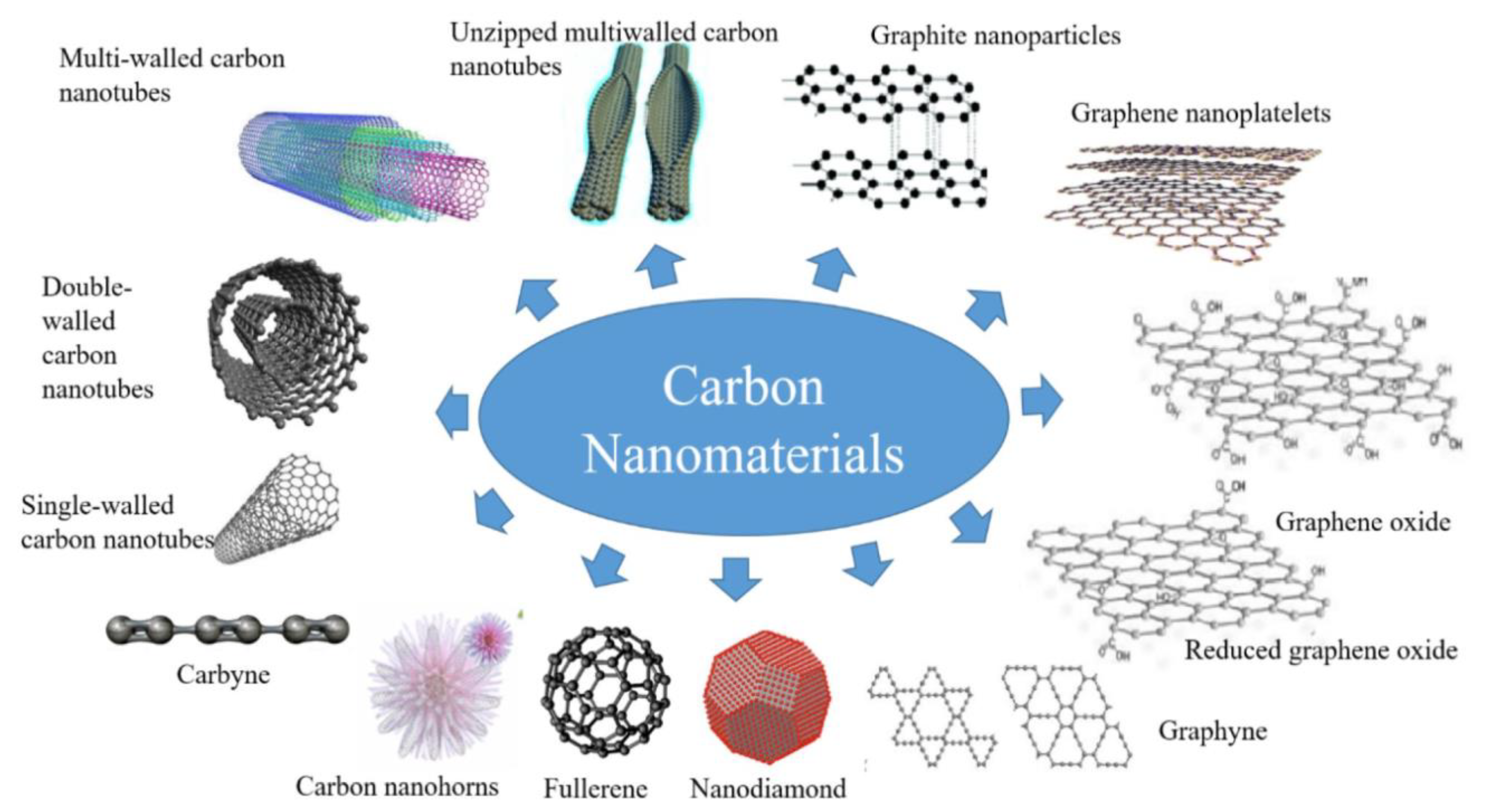
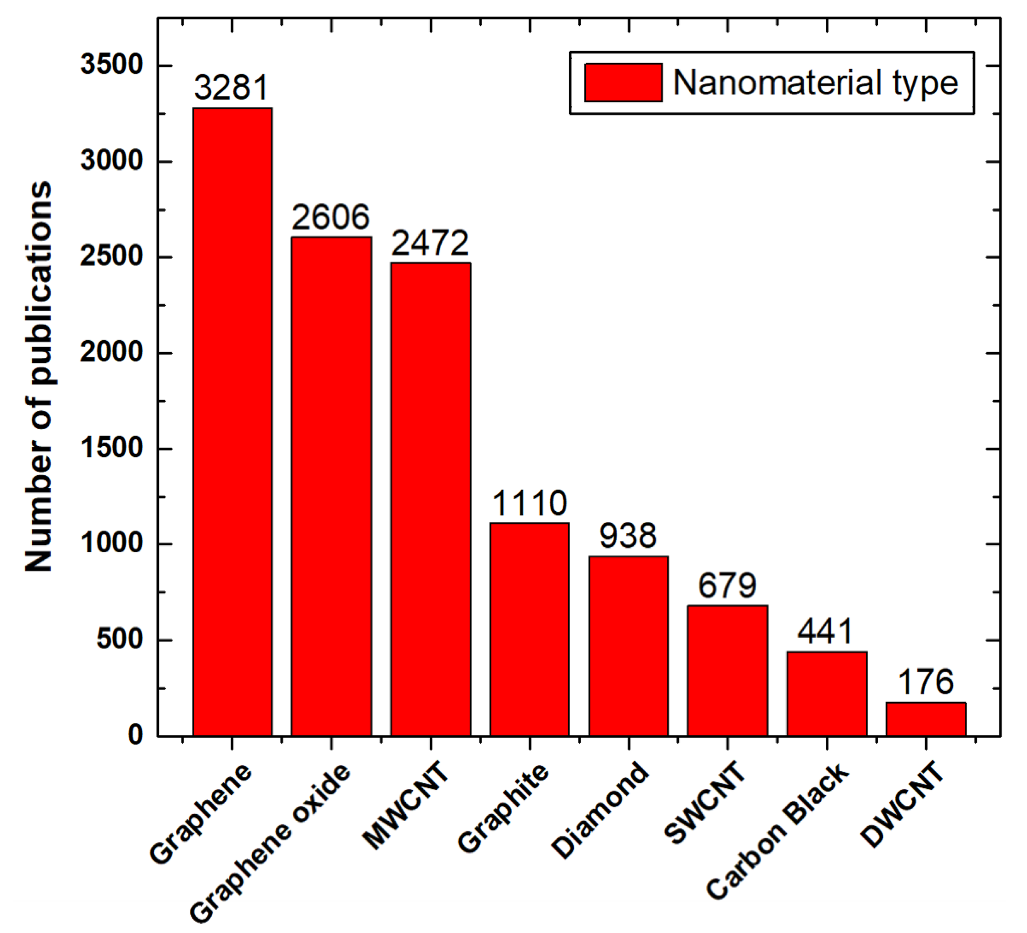
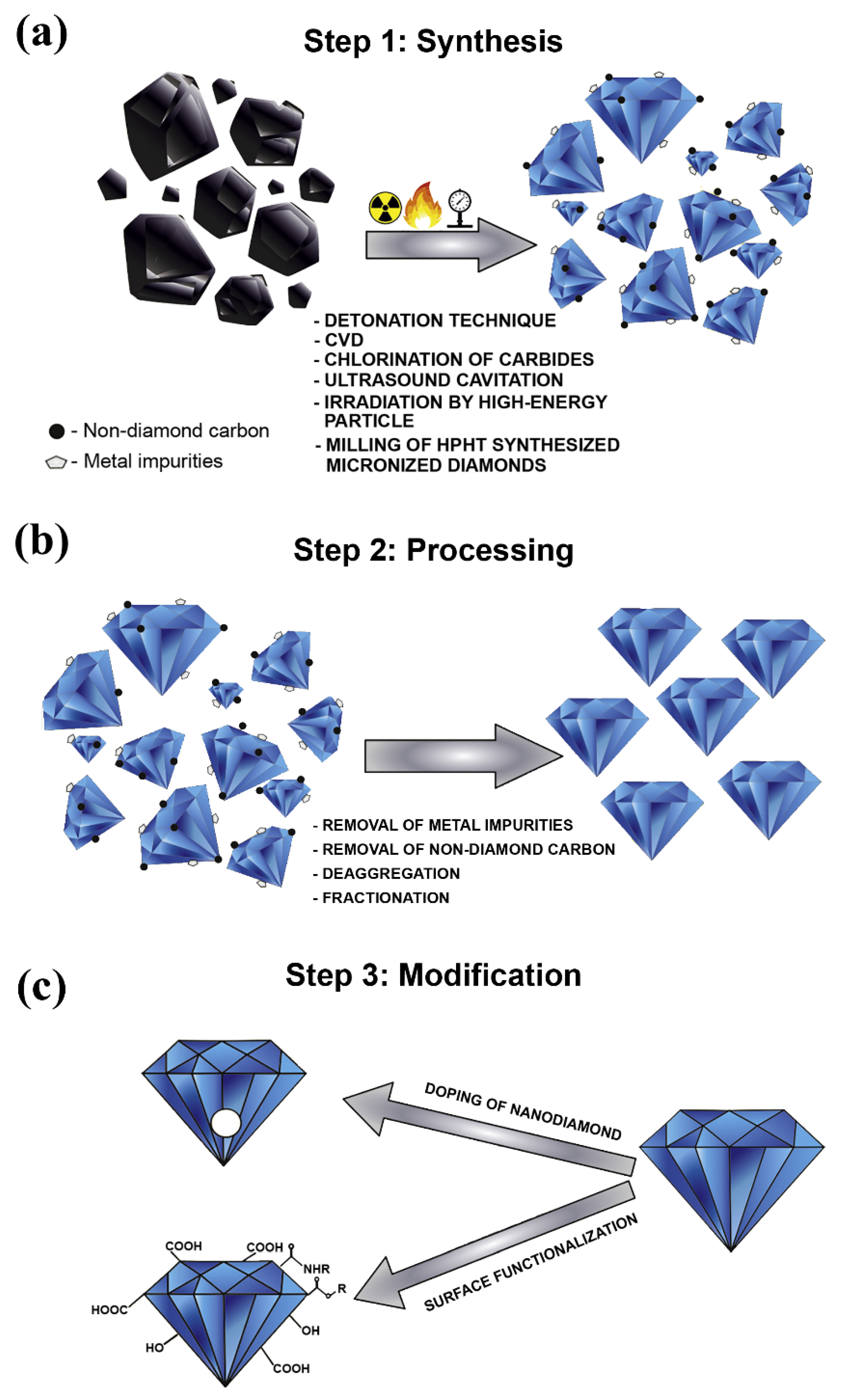
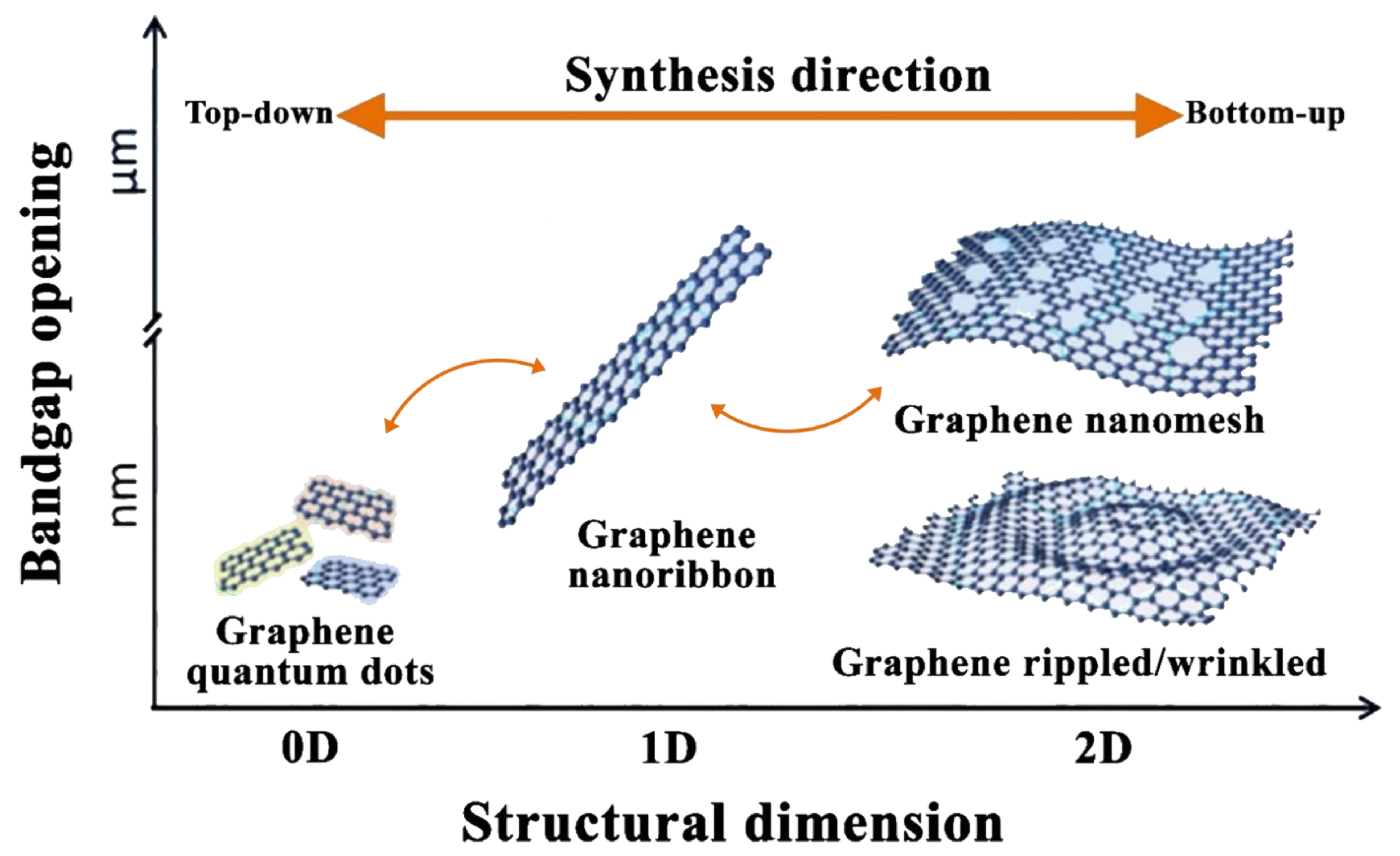
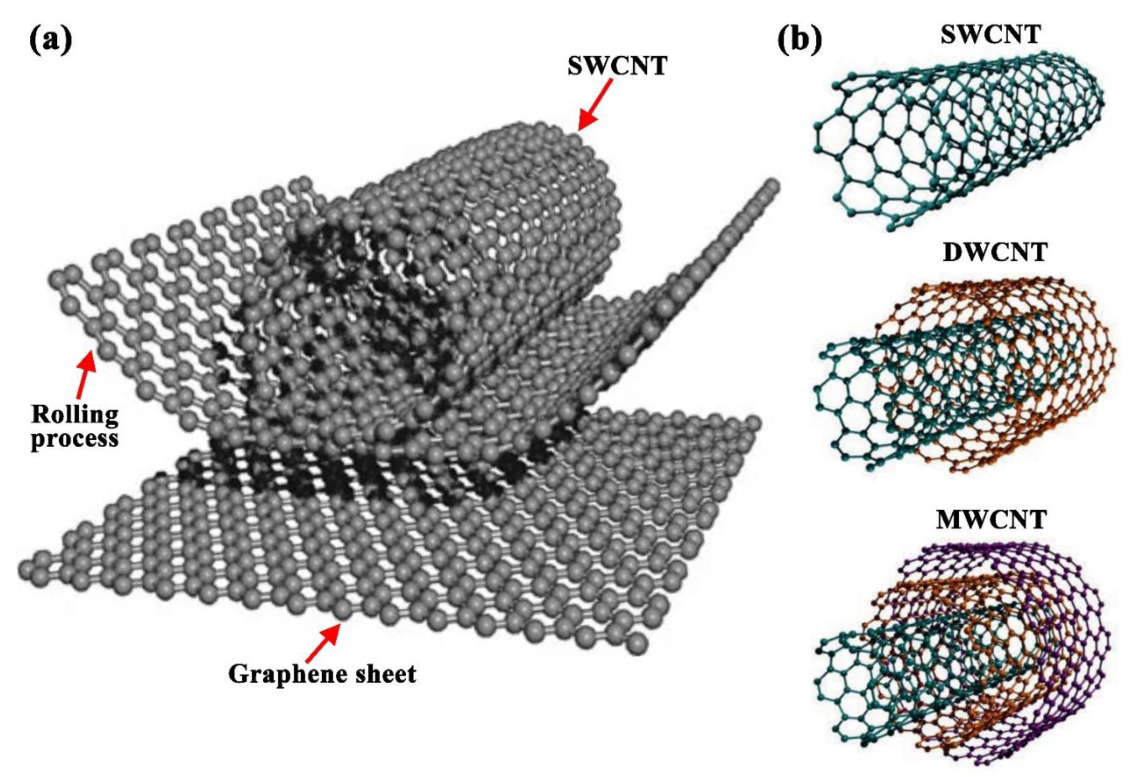
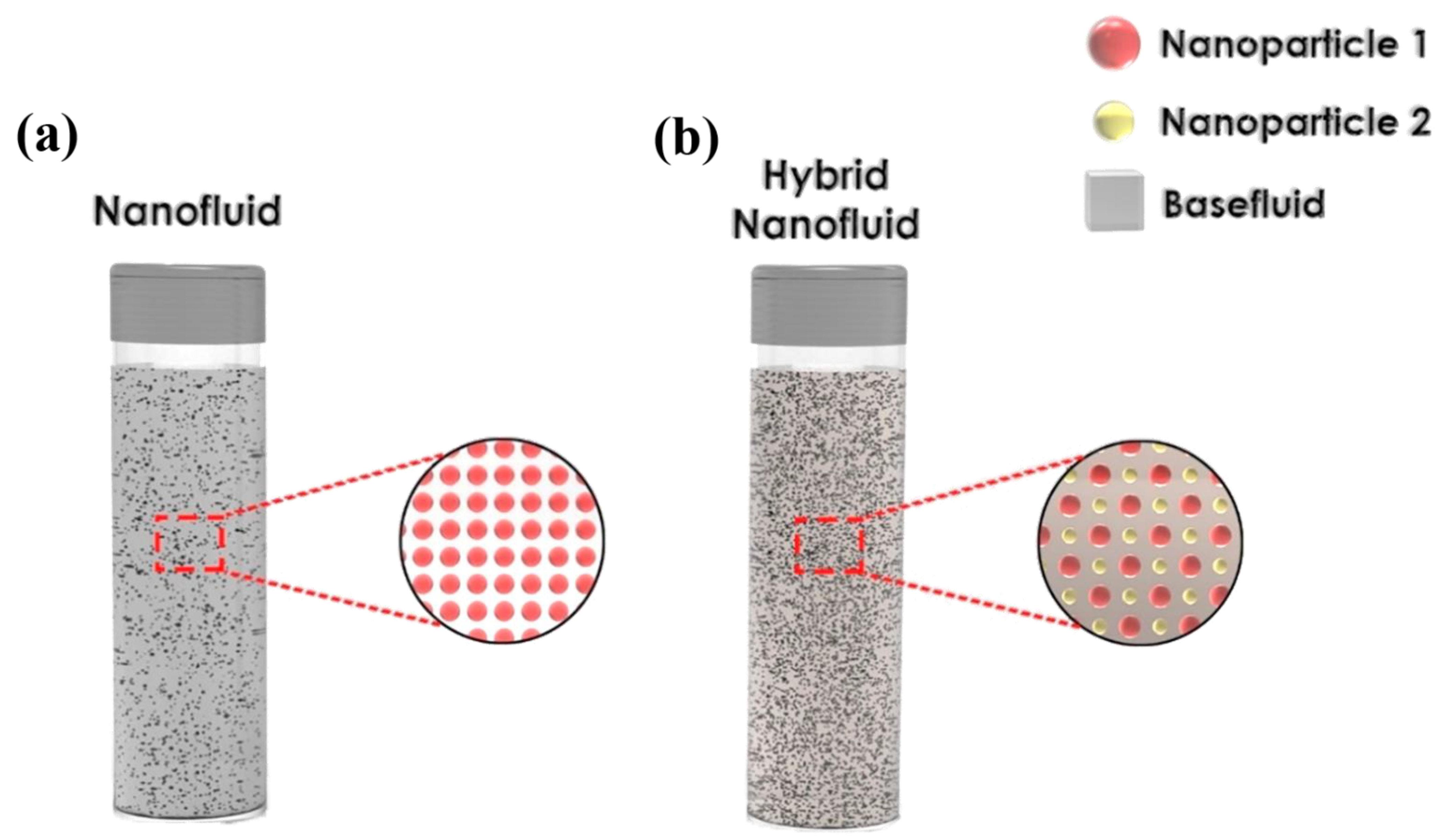
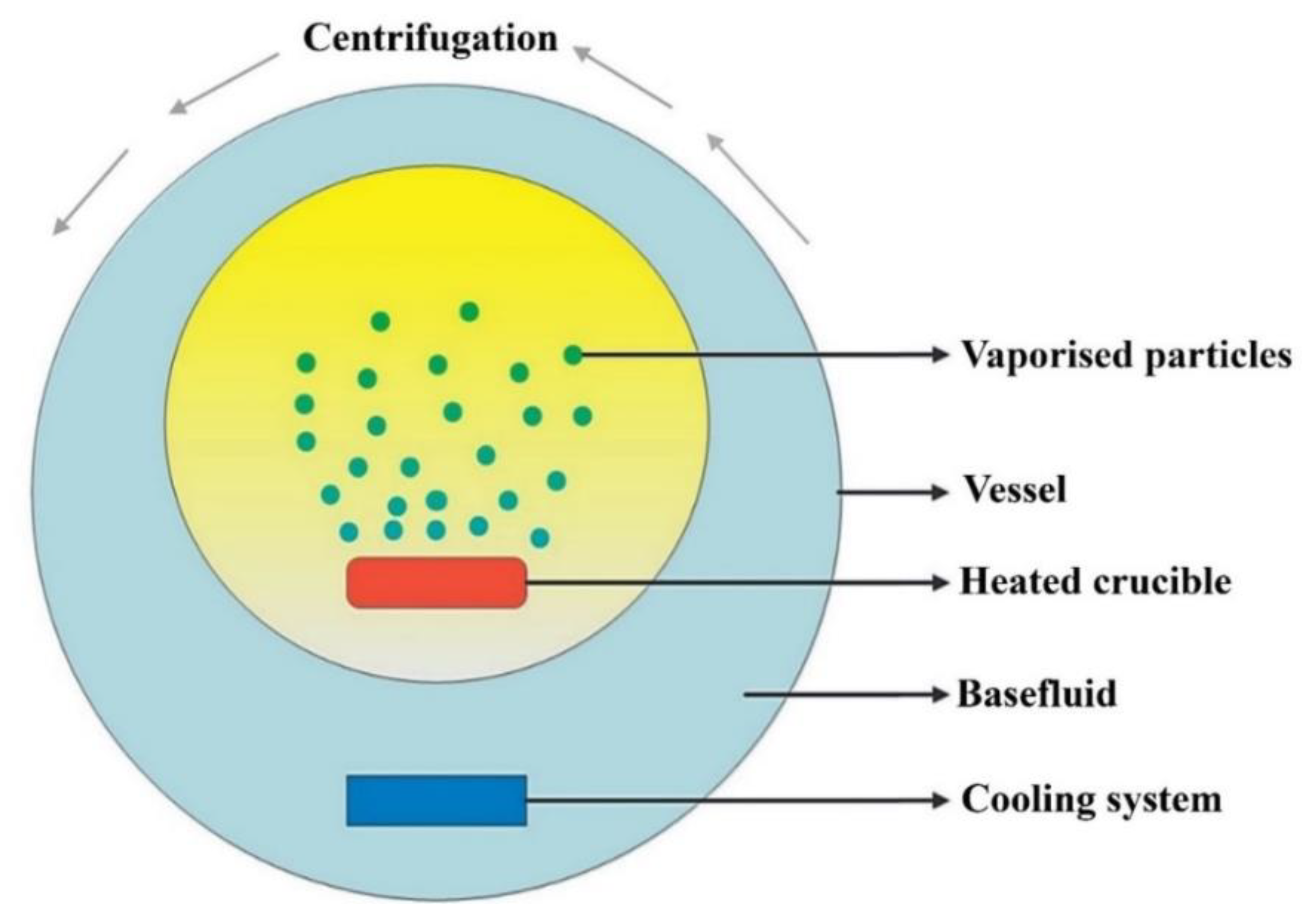
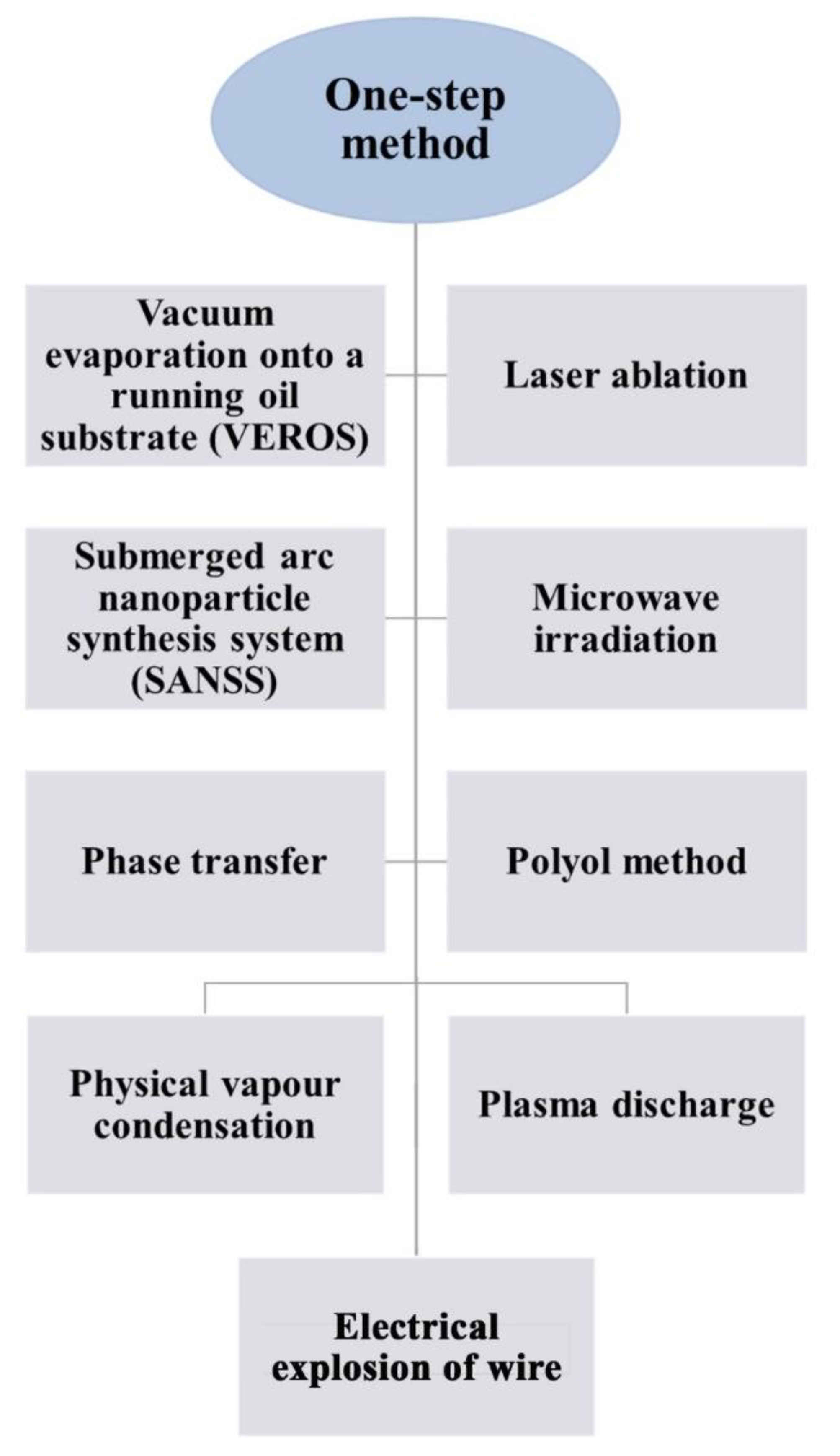
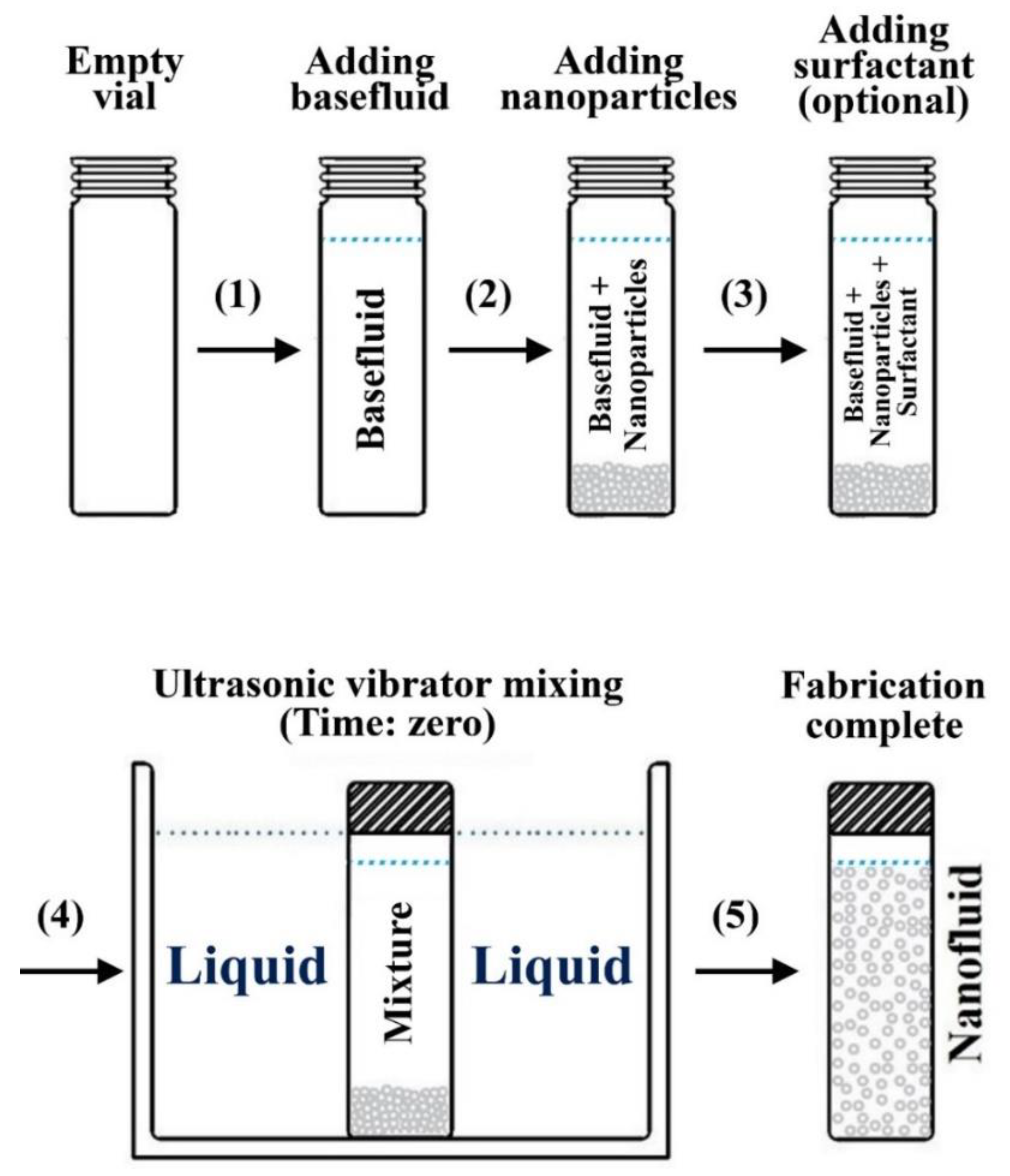
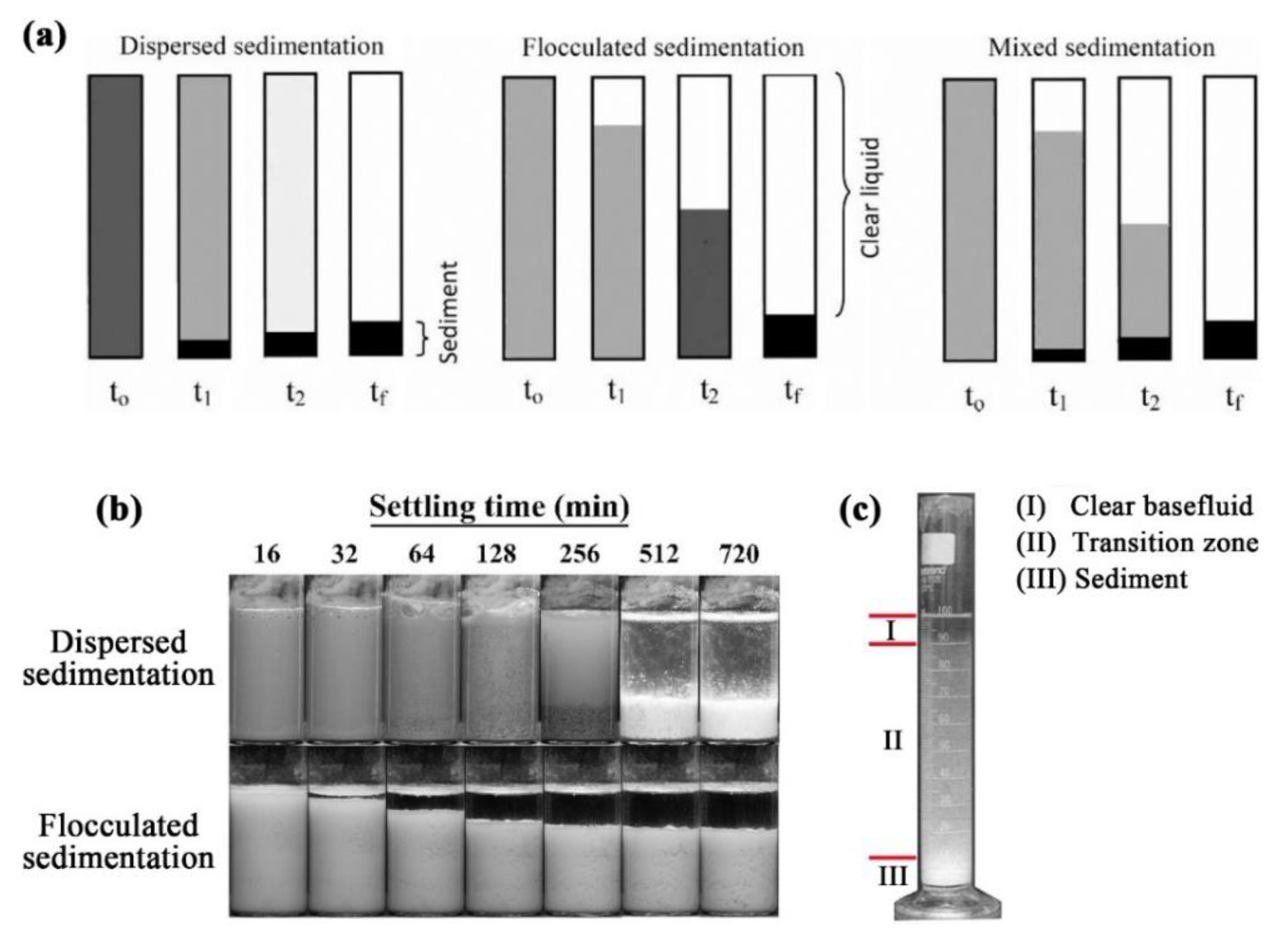
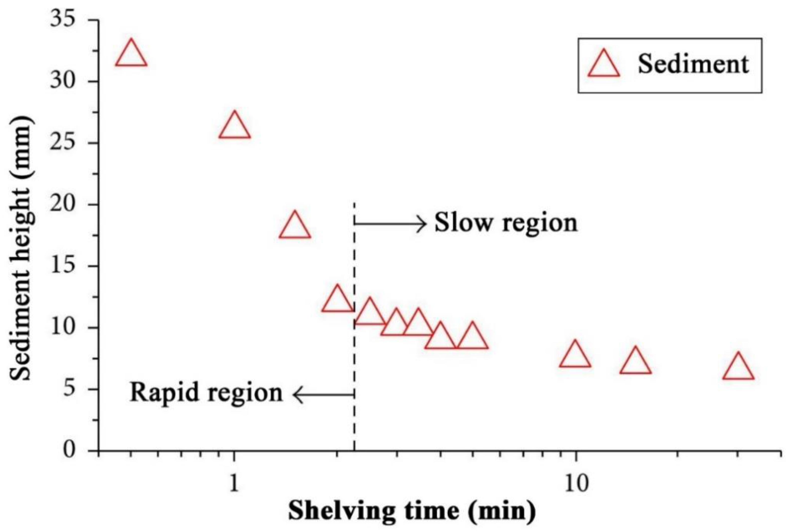
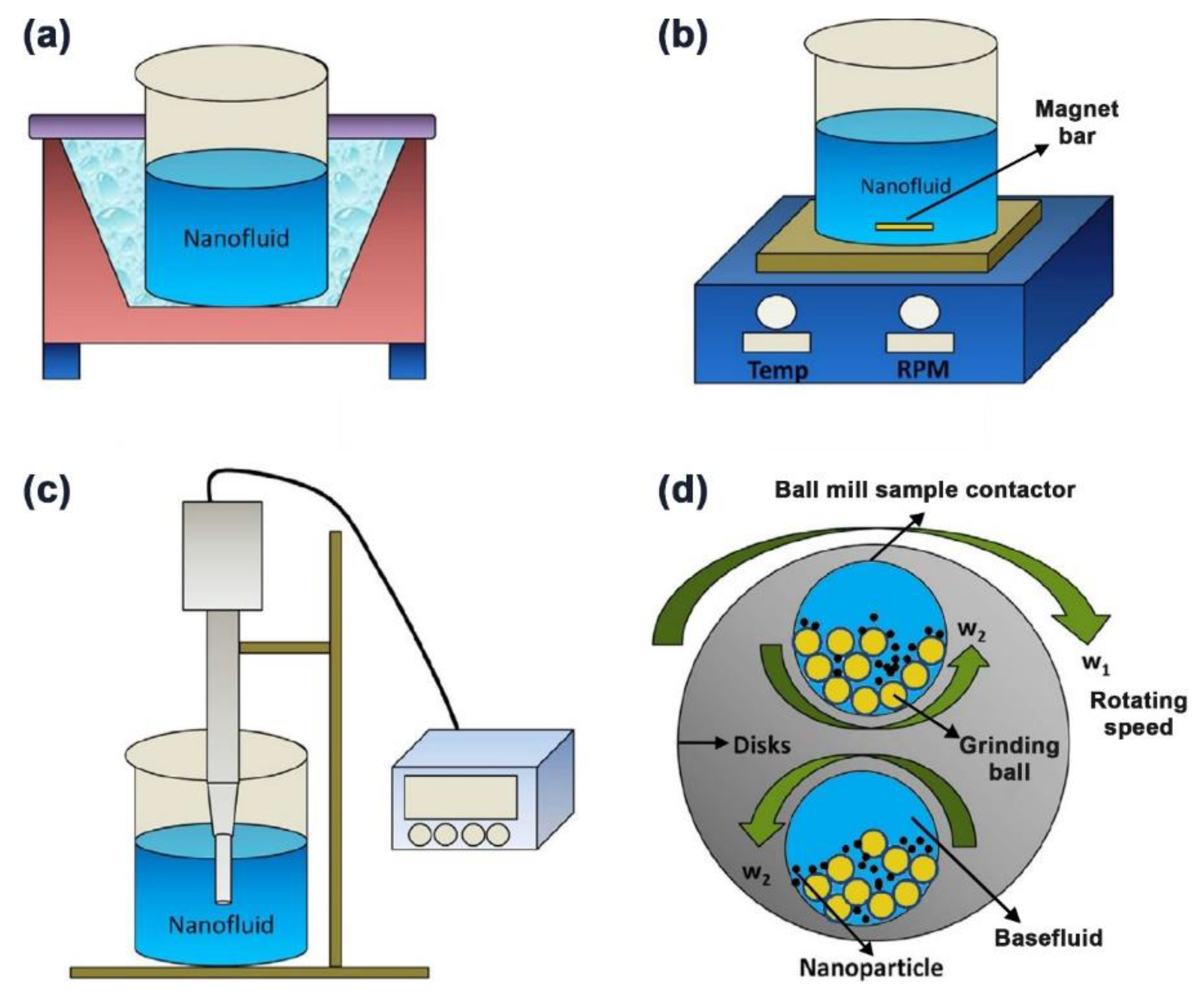
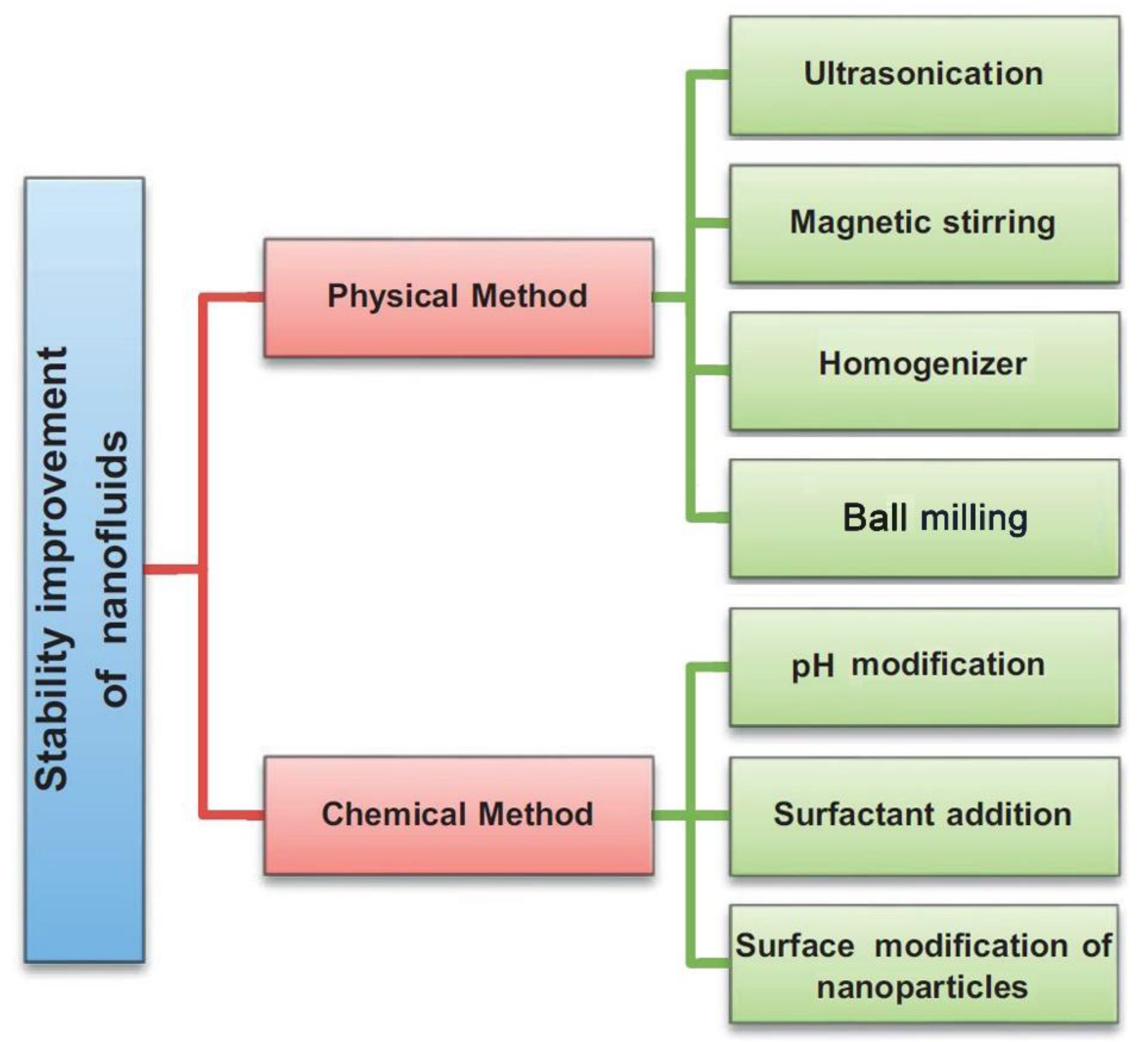
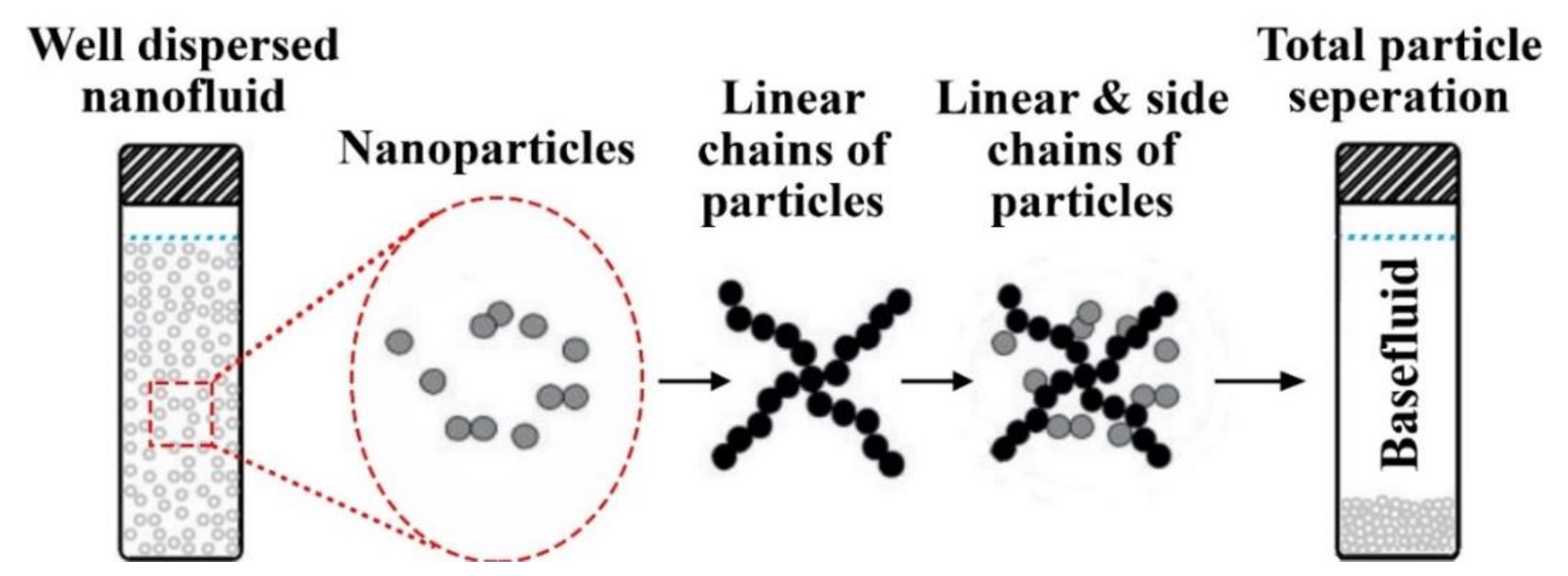
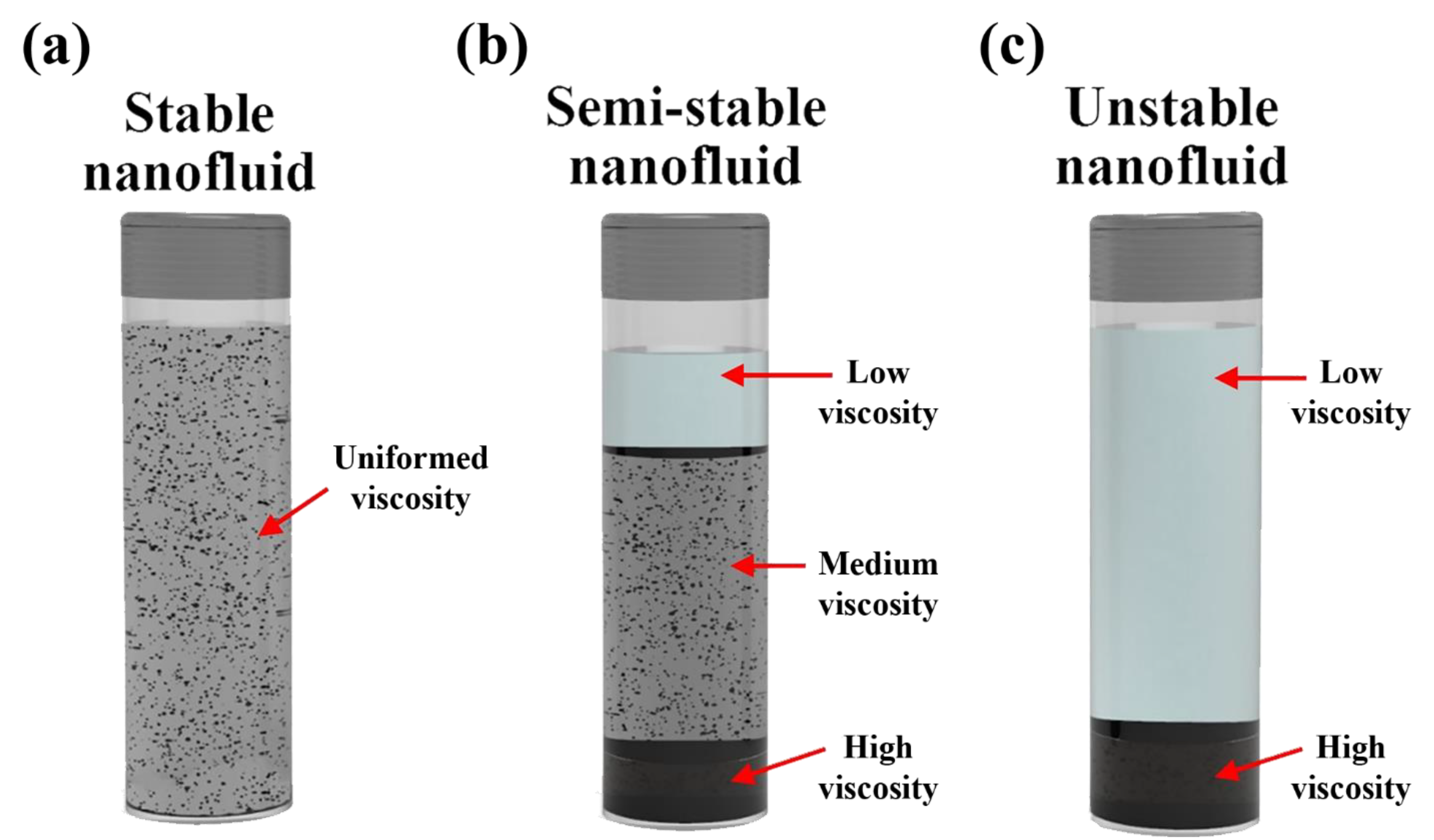
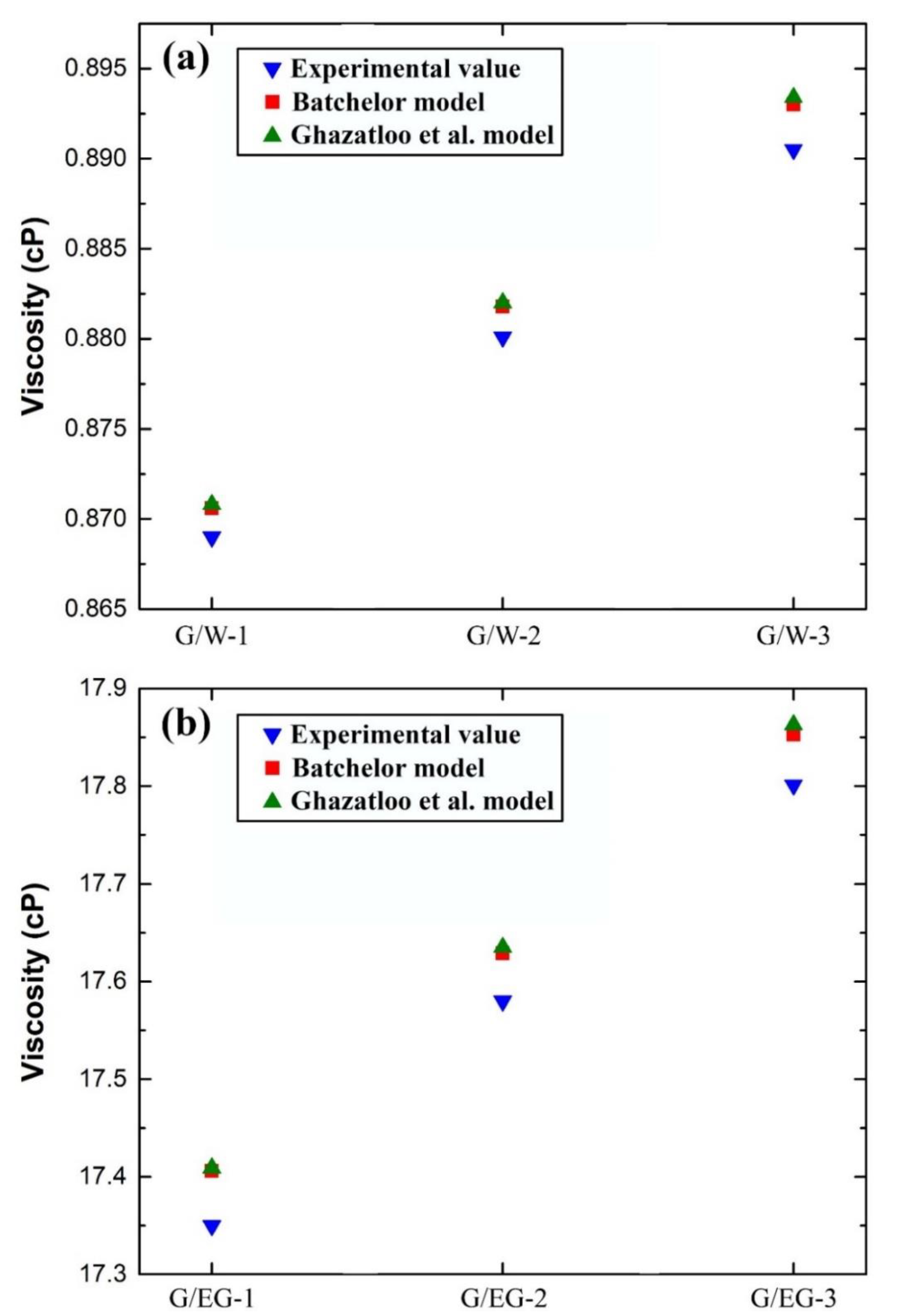
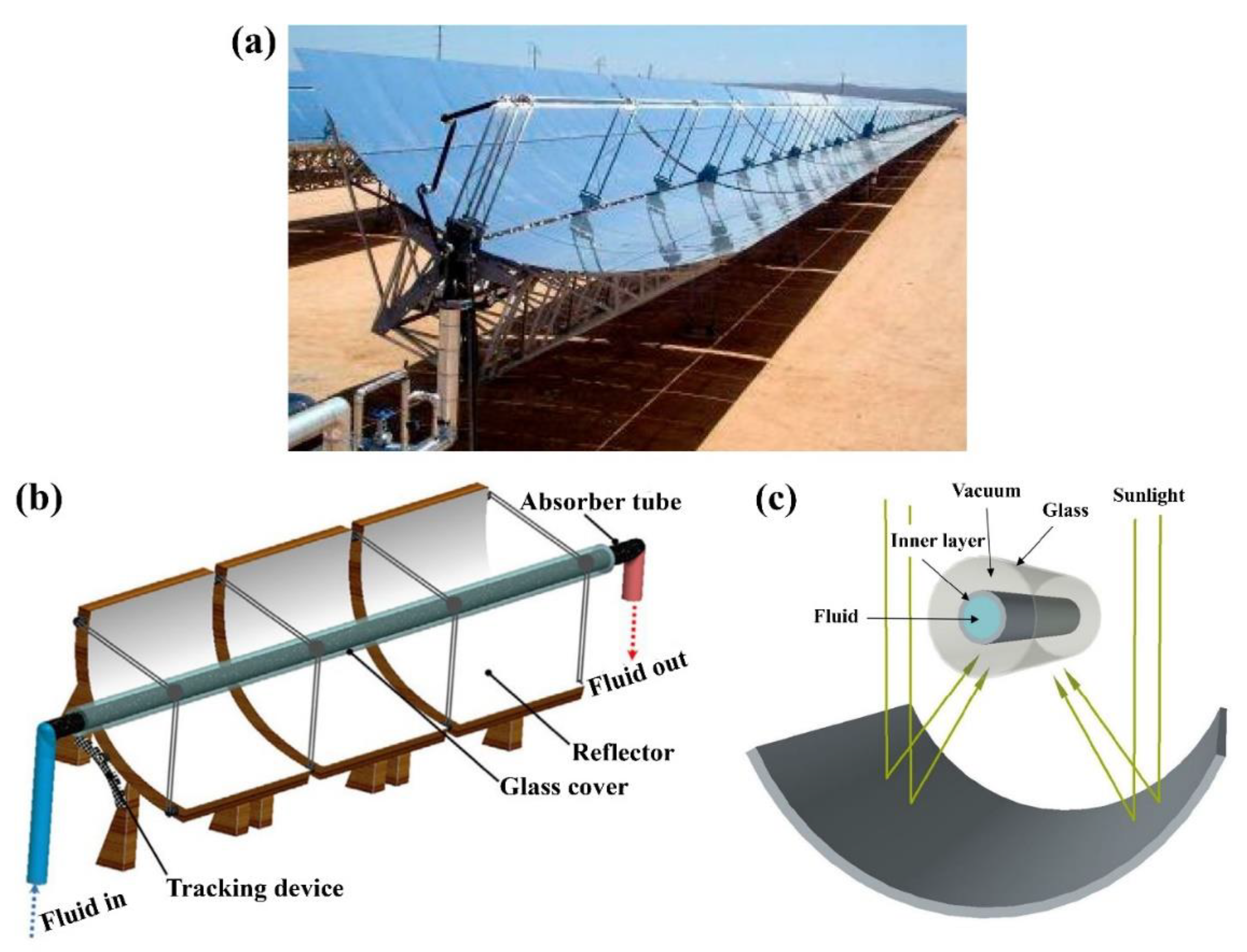
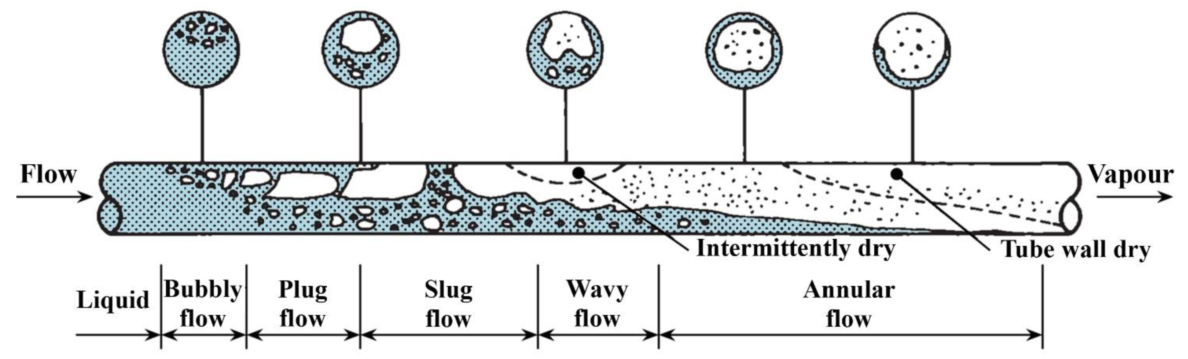
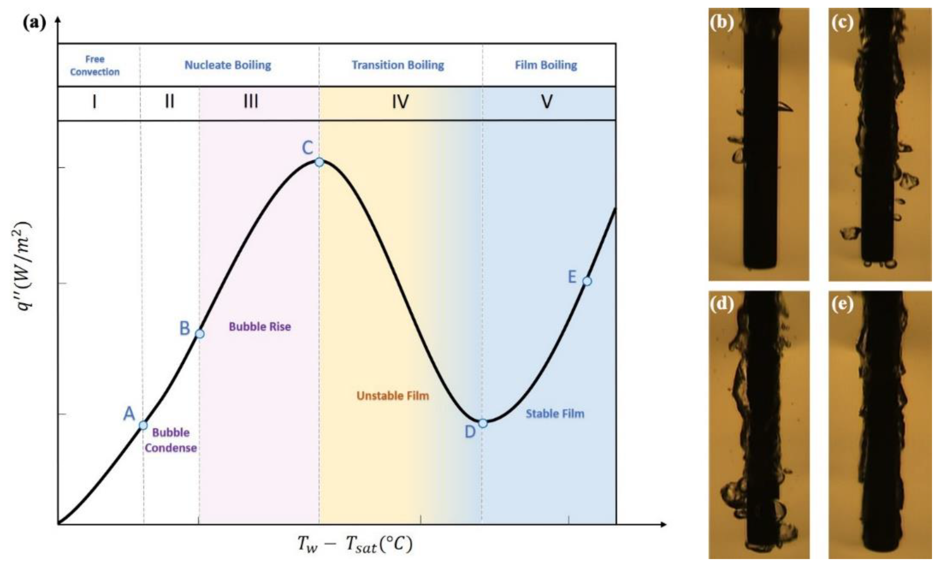
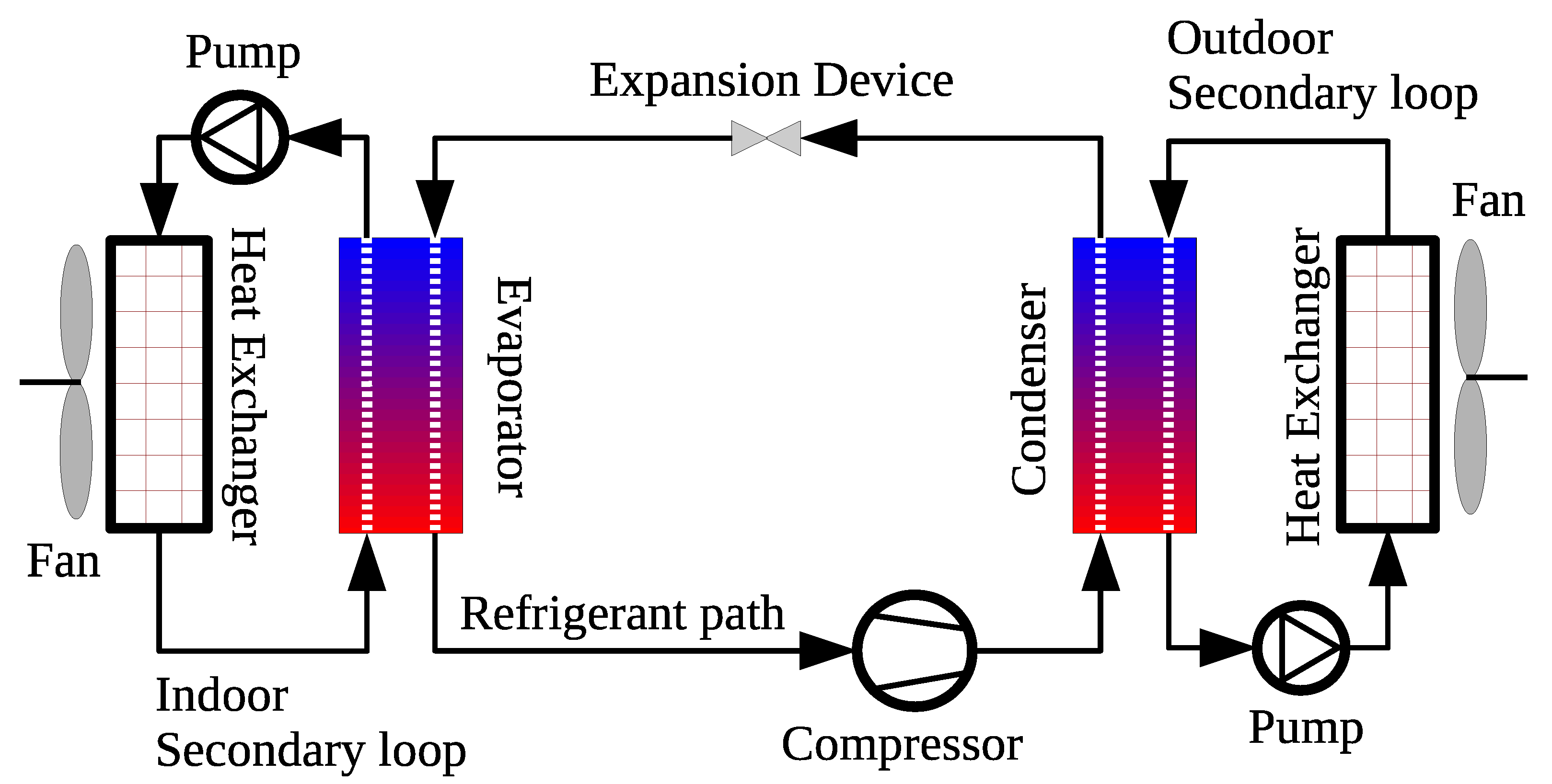
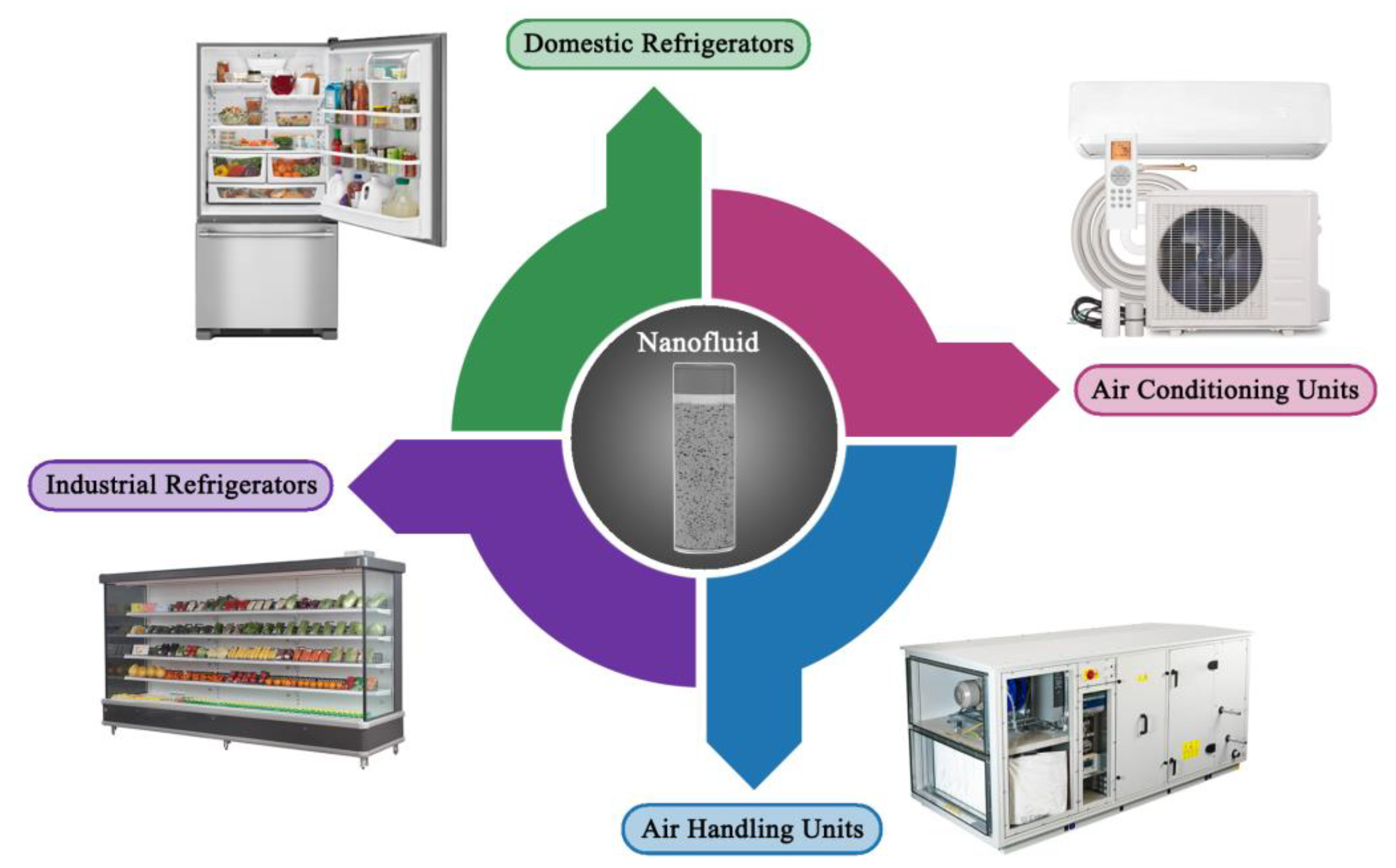
Figure 1. Thermal conductivity of commonly used particles and base fluids for fabricating nanofluids showing an order of magnitude higher in the thermal property for some of the carbon-based materials.
Nanomaterials 11 01628 g001
Figure 2. Search result obtained from Scopus database on nanofluids, where (a) illustrates the number of published works per year and (b) shows the percentage of each type of these documents [35].
Nanomaterials 11 01628 g002
Figure 3. Common allotropes of carbon nanomaterials that grant distinctive thermophysical properties [50].
Nanomaterials 11 01628 g003
Figure 4. The number of publications available at the Scopus database for common carbon-based material used in nanofluids fabrication [35].
Nanomaterials 11 01628 g004
Figure 5. Phases involved in the production process of nanodiamonds, where (a) illustrates the synthesis phase, (b) demonstrates the processing phase, and (c) shows the modification phase. Reproduced with permission from [84]. Elsevier, 2019.
Nanomaterials 11 01628 g005
Figure 6. Different forms of graphene based on their dimensionality and bandgap opening, where graphene quantum dots, graphene nanoribbon, and both graphene nanomesh and graphene rippled/wrinkled have a structural dimension of 0D, 1D, and 2D, respectively.
Nanomaterials 11 01628 g006
Figure 7. Carbon nanotubes formation and classifications, where (a) illustrates the rolling mechanism of graphene sheet into SWCNT and (b) demonstrates the three different categories of CNTs, namely SWCNT, DWCNT, and MWCNT.
Nanomaterials 11 01628 g007
Figure 8. Schematic demonstration to compare between conventional (a) and hybrid (b) nanofluids that uses the same base fluid.
Nanomaterials 11 01628 g008
Figure 9. Eastman et al. [21] one-step method of evaporation and centrifugation for nanofluids fabrication [37].
Nanomaterials 11 01628 g009
Figure 10. Different nanofluid production approaches that fall under the one-step method.
Nanomaterials 11 01628 g010
Figure 11. Example of nanofluids two-step preparation using a bath type ultrasonic device.
Nanomaterials 11 01628 g011
Figure 12. The three types of sedimentation behaviours, where (a) shows their schematic mechanism from the starting time (to) to the finishing time (tf) [8], (b) demonstrates the dispersed and flocculated sedimentation behaviors from Ali et al. [8] experimental work, and (c) represents the mixed sedimentation behavior shown in Ma and Alain [174] investigation.
Nanomaterials 11 01628 g012
Figure 13. A demonstration of the two sedimentation regions in terms of settling speed, where (the left side) shows the rapid region in which the sediment height changes rapidly, and (the right side) illustrates the slow region, where the changes in the sediment height are very slow to the point where it can be negligible [13].
Nanomaterials 11 01628 g013
Figure 14. Physical dispersion stability enhancement devices, where (a) shows the ultrasonic bath sonicator, (b) demonstrate the magnetic stirrer, (c) illustrates the homogenizer/prob sonicator, and (d) shows the ball milling device. Reproduced with permission from [116]. Elsevier, 2020.
Nanomaterials 11 01628 g014
Figure 15. Nanofluids stability improvement methods categorized by their physical and chemical methods.
Nanomaterials 11 01628 g015
Figure 16. Nanoparticles separation due to the formation of both linear and side chains in the base fluid.
Nanomaterials 11 01628 g016
Figure 17. Nanofluids viscosity classification, where (a) shows the stable, (b) illustrates semistable, and (c) demonstrates the unstable cases of the suspension.
Nanomaterials 11 01628 g017
Figure 18. Comparison between the Ghazatloo et al. [269] model, Batchelor [270] model, and experimental effective viscosity, where (a) shows the results for graphene–water nanofluid of 0.5 vol. % (G/W-1), 1.0 vol. % (G/W-2), and 1.5 vol. % (G/W-3), and (b) illustrates the values for graphene–EG suspensions of 0.5 vol. % (G/EG-1), 1.0 vol. % (G/EG-2), and 1.5 vol. % (G/EG-3).
Nanomaterials 11 01628 g018
Figure 19. Example of a parabolic trough solar collector system, where (a) shows the physical device, (b) illustrates its schematic diagram, and (c) demonstrates the reflection mechanism of solar radiation on the absorber tube [298].
Nanomaterials 11 01628 g019
Figure 20. Flow boiling regimes inside a horizontal tube from liquid to vapor phases [327].
Nanomaterials 11 01628 g020
Figure 21. Boiling curve for stagnant water at atmospheric pressure (1 atm), where (a) shows the boiling curve and (be) illustrates the bubble formation within the free convection, nucleate boiling, transition boiling, and film boiling regimes.
Nanomaterials 11 01628 g021
Figure 22. Schematic for a typical vapor compression system with secondary heating and cooling loops.
Nanomaterials 11 01628 g022
Figure 23. Nanofluids employment in AC&R applications, namely; air conditioning units, air handling units, industrial refrigerators, and domestic refrigerators.
Nanomaterials 11 01628 g023
Table 1. Fraction calculation Formulae for different forms of nanofluids.
Type of ParticlesType of Base-FluidFraction (%)FormulaeRef.Eq.
Single typeSingle typevol. V n p V n p + V b f × 100 ;  
or   ( m ρ ) n p ( m ρ ) n p + ( m ρ ) b f × 100
[13,37](1)
Single typeTwo typevol. ( m ρ ) n p   ( m ρ ) n p + [ ( m ρ ) b f 1 + ( m ρ ) b f 2 ]   × 100 ;
where   b f 1   and   b f 2 have equal volume ratio
[141](2)
Two typeSingle typevol. ( m ρ ) n p 1 + ( m ρ ) n p 2   [ ( m ρ ) n p 1 + ( m ρ ) n p 2 ] + ( m ρ ) b f × 100 ;
where   n p 1   and   n p 2 have equal volume ratio
[142,143](3)
Two typeTwo typevol. ( m ρ ) n p 1 +   ( m ρ ) n p 2   [ ( m ρ ) n p 1 + ( m ρ ) n p 2 ] + [ ( m ρ ) b f 1 + ( m ρ ) b f 2 ]   × 100 ;
where   n p 1   and   n p 2   have   equal   volume   ratio   as   well   as   b f 1   and   b f 2
[144](4)
Table 2. Published work on nanodiamond, graphene, and carbon nanotubes nanofluids produced using the two-step approach.
MaterialBase FluidParticles Dimensions (nm)Particles ConcentrationAdditional InformationRef.
NDEG30–50<1.4 vol. %
-
Dispersion was performed with an ultrasonic vibration device for 3 h.
[149]
EG5–100.25–5.0 vol. %
-
Purification and surface modification of the particles were done using a mixture of nitric acid, perchloric acid, and hydrochloric acid.
-
Dispersion was performed via continuous sonication.
[150]
EG5–100.25–1.0 vol. %
-
Purification and surface modification of the particles were done using a mixture of nitric acid and perchloric acid.
-
Nanofluid pH adjustment: 7–10.
-
Dispersion was performed by magnetic stirring and ultrasonic sonication for 3 h.
[151]
EG—water30–50 0. 5–2.0 vol. %
-
Purification and surface modification of the particles were done using a mixture of nitric acid, perchloric acid, and hydrochloric acid.
-
Base fluid used was a mixture of 55% distilled water and 45% of EG.
-
Dispersion was performed by sonication for 3 h.
[152]
EG and mineral oil 52.0 g
-
NDs were prepared by detonation followed by functionalization.
-
For the EG base fluid: the particles and 48 g of dimethylsulfoxide (DMSO) were bath sonicated for 30 min then magnetic stirred with 50 mL of glycidol for 24 h.
-
For the mineral oil base fluid: the particles, 2.0 g of oleic acid, and 63 g of octane were bath sonicated for 1 h
[153]
Highly refined thermal oil3–10 0.25–1.0 wt %
-
Non-ionic sorbitane trioleate (Span 85) was used as a surfactant in a surfactant to particles ratio of 7:1.
-
Dispersion was performed by a probe-type sonicator for 1 h.
[154]
Naphthenic transformer oil (NTO)101.0 g
-
The particles, 2.0 g of oleic acid, and 50 g of octane were high energy ultrasonicated for 30 min.
-
The previous mixture was added to the base fluid then sonicated for an additional 1.0 h.
[155]
propylene glycol (PG)—water5–10 0.2–1.0 vol. %
-
The particles were initially purified then treated with acid.
-
The base fluid contained a mixture of PG and water at ratios of 20:80, 40:60, and 60:40, respectively.
-
Fabrication was performed through a bath type sonicator for 2.0 h.
[156]
GrapheneWater 2–5 *10 mg/mL
-
Graphene powder was produced through a modified hummer method (i.e., mechanical exfoliation) followed by surface treatment.
-
Nanofluid fabrication was done through mixture centrifugation at 6000 rpm for 10 min.
[157]
Water6000–8000 *0.001–0.01 vol. %
-
Graphene powder was initially oxidized using sulfuric acid and nitric acid.
-
Nanofluid was produced by ultrasonicating the mixture for 2.0 h.
[158]
Water2 *0.025–0.1 wt %
-
Graphene powder was initially oxidized using sulfuric acid and nitric acid.
-
Nanofluid was produced by continuous sonication using a high-power probe type ultrasonicator.
[159]
EG and water0.005–0.056 vol. %
-
Fabricated graphene was treated with acid for better dispersion.
-
Nanofluid was produced by sonicating the mixture for 30–45 min.
-
Solution pH value was adjusted to around 6–7.
[160]
Glycerol15–50 *13 wt %
-
Graphene was surface functionalized.
-
Nanofluid was produced by sonicating the mixture for 10 min.
[161]
CNTsWater 9–15 ^0.5 wt %
-
MWCNTs powder was surface functionalized via nitric and sulfuric acid of 1:3 ratio, respectively.
-
Nanofluid was produced by probe sonication for 5 min.
[162]
Vegetable cutting oil10–20 ^0.6 vol. %
-
Functionalized MWCNTs were used.
-
Fabrication process consisted of three mixing stages: 1—mechanical mixing for 60 min at 750 rpm, 2—ultrasonic homogenizer for 60 min, and 3—magnetic stirring for 60 min at 1500 rpm.
[163]
Turbine meter oil5–16.1 ^0.05–0.4 wt %
-
Triton X100 was added as a surfactant to the base fluid in a ratio of 1:3, respectively.
-
Fabrication process consisted of: 1—mixing the surfactant with the base fluid using an electric mixer for 20 min at 1500 rpm, 2—adding and dispersing the MWCNTs using the same device for 4 h, 3—additional mixing using a probe sonicator for 2 h.
[164]
Water 2–4 ^0.01–0.5 vol. %
-
DWCNTs functionalized by carboxylic acid were used.
-
Nanofluid production was conducted by magnetic stirring for 2.5 h, followed by ultrasonication for 5 h.
[165]
EG2–4 ^0.02–0.6 vol. %
-
DWCNTs functionalized by carboxylic acid were used.
-
Fabrication was performed by magnetic stirring for 2.5 h, then sonication for 6 h.
[166]
Water1–2 ^0.1–0.5 vol. %
-
SWCNTs nanofluids were prepared by first adding sodium dodecyl sulfate (SDS) surfactant then mixing with a high-pressure homogenizer for 1 h.
[167]
Water0.8–1.6 ^0.3 vol. %
-
Nanofluid production consisted of SWCNTs, sodium deoxycholate surfactant (0.75 vol. %), and the base fluid.
-
Mixing was conducted by bath sonication for 6 h, followed by probe sonication for 2 h.
[168]
Note: * and ^ refers to graphene sheet thickness and CNTs outer diameter, respectively.
Table 3. Examples of surfactants used in nanofluids fabrication categorized by classifications based on their head group charge.
Surfactant ClassificationHead Group ChargeExample(s)
Cationic+veCetyltrimethyl ammonium bromide (CTAB), distearyl dimethyl ammonium chloride (DSDMAC), and benzalkonium chloride (BAC).
Non-ionicneutral or unchargedOleic acid, polyvinylpyrrolidone (PVP), Arabic gum (AG), Tween 80, and oleylamine.
Anionic−veSodium dodecyl benzenesulfonate (SDBS), and SDS.
Amphoteric+ve and −velecithin.
Table 4. Developments of nanofluids effective thermal conductivity formulas.
Developer/sYearFormulaDependent ParameterLimitations
Maxwell [231]1890 k e f f k b f = k n p + 2 k b f + 2   f V   ( k n p k b f ) k n p + 2 k b f f V   ( k n p k b f ) ;
where   k e f f ,   k b f ,   and   k n p are the effective thermal conductivity of the nanofluid, base fluid thermal conductivity, and nanoparticles thermal conductivity, respectively.
f V Suited for spherical shaped particles.
Jefferson et al. [232]1958 k e f f = k b f { ( 1 1.21   f V 2 / 3 ) + 0.4875   f V 1 / 3   [ ln k n p k b f 1 0.25 + ( 0.403   f V 1 / 3 0.5 ) ( ln k n p k b f 1 ) ] }   f V The model is used for spherical particles but always underestimate the effective thermal conductivity by 25%.
Hamilton and Crosser [233]1962 k e f f k b f = k n p + ( n 1 ) k b f ( n 1 )   f V   ( k b f k n p ) k n p + ( n 1 ) k b f f V   ( k b f k n p ) f V   and   n Preferred for spherical and cylindrical shaped particles with n = 3/ψ, where n and ψ are the empirical shape factor and particle sphericity, respectively. For perfectly spherical particles ψ = 1.
Wasp et al. [234]1977 k e f f k b f = k n p + 2 k b f 2   f V   ( k b f k n p ) k n p + 2 k b f + f V   ( k b f k n p ) f V Particles should have a sphericity of ≤1.
Yu and Choi [235]2003 k e f f k b f = k n p + 2 k b f + 2   f V   ( k n p k b f ) ( 1 + β ) 3 k n p + 2 k b f f V   ( k b f k n p ) ( 1 + β ) 3 ;
where β is the ratio of the nanolayer thickness to the particle radius.
f V , interfacial particle layer, and radiusModified version of the Maxwell [231] model for spherical particles. The main problem is that it is inadequate the non-linear trend of thermal conductivity.
Xuan et al. [236]2003 k e f f k b f = k n p + 2 k b f 2   f V   ( k b f k n p ) k n p + 2 k b f + f V   ( k b f k n p ) + f V   ρ n p   C n p 2 k b f   k B T 3 π r c ν ;
where k B is the Boltzmann constant (1.381 × 10⁻²³ J/K), T is the temperature of the mixture, r c is the particle apparent radius, and ν is the kinematic viscosity of the liquid.
f V , ρ n p , C n p , T , r c , and ν Hard to predict the thermal conductivity for linear temperatures.
Nan et al. [237]2003 k e f f k b f = 3 + f V ( k n p k b f ) 3 2 f V f V Can only be used with CNTs nanofluids.
Kumar et al. [218]2004 k e f f k b f = 1 + c 2 k B   T   f V   r m π   ν   d n p 2   k b f   ( 1   f V )   r np ;
-
For none-spherical particles: d n p = 6 V n p A n p ;
-
For CNTs: d n p = 1.5   a b a + ( b 2 ) ;
where c is a constant value from 2.9 to 3.0,   r m is the radius of the fluid medium particles, r np is the particles radius, d n p is the nanoparticles mean diameter, V n p is the volume of the particles, A n p is the area of the particles, a is the length of the CNT, and b is the outer diameter of the CNT.
f V dimensions of the particles, T , and νThe Brownian motion has the dominative effect on the thermal conductivity prediction over all other factors.
Jang and Choi [213]2004 k e f f = k b f ( 1   f V ) + k n p     f V + 3 C 1 ( d b f d n p ) k b f   f V   R e d n p 2   P r ;
-
R e d n p = C R . M .   d n p ν ;
-
C R . M . = k B   T 3   π μ d n p   b f ;
where C1 is a proportional constant, dbf is the diameter of the base fluid molecule, R e d n p is the Reynolds number as defined above, Pr is the Prandtl number, CR.M. is the nanoparticle random motion velocity, and b f is the mean-free path of the base fluid molecule.
  f V dimensions of the particles, T , ν, and b f Both conduction and convection heat transfer are accounted for, while the heating duration is much higher.
Yu and Choi [238]2004 k e f f k b f = 1 + n f V e A 1 f V e A ;
-
f V e = r   f V ;
-
A = 1 3   j = a , b , c k p j k b f k p j ( n 1 ) k b f   ;
where f V e is the equivalent volume concentration of complex ellipsoids particles, r is the volume ratio, a ,   b , and c are the semi-axes of the particle (for sphere a = b = c ), A is a parameter that reflects the equation shown above, and k p j is the equivalent thermal conductivity of the ellipsoids particle.
f V ,   n , and interfacial resistanceThis is a renovated Hamilton and Crosser [233] model with n = 3/ψ−α, where α is an empirical parameter that depends on both particle sphericity and the particle to liquid thermal conductivity ratio. In addition, this model includes the interface layer between the particles and the surrounding liquid but cannot predict the nonlinear behaviour of the thermal conductivity.
Prasher et al. [239]2005 k e f f k b f = ( 1 + A   f V   R e m   P r 0.333 )   ( 1 + 2 α ) + 2   f V ( 1 α )   ( 1 + 2 α )   f V ( 1 α ) ;
-
α = 2   R b   K m d n p ;
where A is a constant that is independent of the type of base fluid, m is a constant that depends on the base fluid type, R e is the Reynolds number, α is a parameter that reflects the equation shown above, R b is the impact of interfacial resistance with a magnitude in the range of 0.77 × 10⁻⁸ to 20 × 10−8 Km 2   W 1 , and Km is the matrix conductivity.
f V , R b , and d n p Only considers the dispersed particles convection effect.
Xue [240]2005 k e f f k b f = 1   f V + 2   f V ( k n p k n p k b f )   ln ( k n p + k b f 2 k b f ) 1   f V + 2   f V ( k b f k n p k b f )   ln ( k n p + k b f 2 k b f )   f V Suitable for nanofluids made of dispersed CNTs.
Murshed et al. [241]2006 k e f f k b f = [ 1 + 0.27   f V 4 3 ( k n p k b f 1 ) ]   [ 1 + 0.52   f V 1 f V 1 3 ( k n p k b f 1 ) ] 1 + f V 4 3 ( k n p k b f 1 )   ( 0.52   f V 1 f V 1 3 + 0.27   f V 1 3 + 0.27 )   f V The particles need to be uniformly dispersed in the suspension for appropriate effective thermal conductivity prediction.
Vajjha et al. [242]2010 k e f f = k n p + 2 k b f 2 ( k b f k n p )   f V k n p + 2 k b f   ( k b f k n p )   f V   k b f + 5 × 10 4 β   f V   ρ b f C p b f k B   T ρ n p   d n p   ƒ   ( T ,   f V ) ;
-
f   ( T ,   f V ) = ( 2.8217 × 10 2   f V + 3.917 × 10 3 ) ( T T o ) + ( 3.0669 × 10 2   f V 3.91123 × 10 3 ) ;
where β is the fraction of the liquid volume that moves with the particle, ƒ   ( T ,   f V ) is a function that depends on the fluid temperature and particles concentration as defined above, and T o is a reference temperature that equals 273 K
  f V , particles type, and base fluid temperatureLimited to nanofluids of temperatures between 295 and 363 K.
Xing et al. [243]2016 k e f f = ( 1 +   η   f V 3 k b f   η k 33 c + 3 H (   η P ) ) k b f + 0.5   f V   ρ C N T   C p C N T   k B   T 3   π   μ   r m ;
-
  η = [ ( 2 × 10 8 ) a 2 13.395   a + 0.2533 ]   f V ( 6988.1   a + 0.1962 )   ;
-
H = 1 P 2 1   [ P P 2 1   ln ( P + P 2 1 ) 1 ] ;
-
P = a b ;
-
k 33 c = k n p 1 + 2 R k   k n p a ;
where η is the modified straightness ratio, H is a factor reflected by the equation defined above, P is the CNT length to diameter ratio, k 33 c is the equivalent thermal conductivity of the CNT along the longitudinal axes, R k is the Kaptiza radius and is equal to 8 × 10⁻⁸ m2 K/W, μ is the dynamic viscosity, ρ C N T is the density of the CNT, and is the C p C N T specific heat capacity of the CNT.
f V , T, and aspect ratioCan only be used for CNTs suspensions. Furthermore, not all of the parameters are accounted in the correlation, while the effect of the micro-motion is the most significant parameter.
Gao et al. [244]2018 k e f f k b f = 3 + η 2   f V   [ k b f   ( 2   R b L + 13.4 t ) ] ( 3 η   f V )   ;
where L is the length of the nanoplatelet, t is the nanoplatelet thickness, and η is the average flatness ratio of the graphene nanoplatelet.
  f V , L , t , R b , and η .This model is designed for suspensions of water, as the base fluid, and graphene nanoplatelet.
Li et al. [245]2019 k e f f k b f = k p e + 2 k b f + 2 ( k p e k b f ) ( 1 t n l r n p ) 3   f V k p e + 2 k b f ( k p e k b f ) ( 1 t n l r n p ) 3   f V   ;
where k p e is the equivalent particle thermal conductivity, and t n l is the thickness of the nanolayer surrounding the particle.
f V , t n l , r n p , and fluid temperatureThis model is a modified form of the Yu and Choi model with the nanolayer constant value changed to quadratic.
Jóźwiak et al. [246]2020 k e f f k b f =   ω f V ( k n p ω k b f ) ( γ 1 2 γ 2 + 1 ) + ( k n p + ω k b f ) γ 1 2 [   f V γ 2 ( ω 1 ) + 1 ] γ 1 2 ( k n p + ω k b f ) ( k n p ω k b f )   f V   ( γ 1 2 + γ 2 1 )   ;
-
ω = k I N k b f ;
-
γ = 1 + t n l r C N T ;
-
γ 1 = 1 + t n l 2 r C N T ;
where ω , γ , γ 1 are factors representing the equations shown above, k I N is the interfacial nanolayer thermal conductivity, and r C N T is the radius of a single CNT.
  f V , and particles morphology This is a modified version of the Murshed et al. [241] model, which is suitable for ionic liquid nanofluids (also known as ionanofluids) with dispersed CNTs.
Table 5. Developments of nanofluids effective viscosity formulas.
Developer/sYearFormulaDependent ParameterLimitations
Einstein [271] 1906 µ e f f = µ b f ( 1 + 2.5 f V ) f V Suited for suspensions of <0.02 vol. % and spherical shaped particles.
Hatschek [272]1913 µ e f f = µ b f ( 1 + 2.5 f V ) f V Designed for suspensions with up to 40 vol. % of spherical particles but does not account for the size of the dispersed particle. The formula also showed very large deviation from the actual viscosity value.
Saitô [273]1950 µ e f f = µ b f ( 1 + 1.25 f V 1 f V 0.87 ) f V Preferred for dispersions of small spherical particles and is affected by the Brownian motion of the particles.
Mooney [274] 1951 µ e f f = µ b f   exp ( 2.5 f V 1 C F f V ) ;
where C F is the self-crowding factor.
f V , and C F This is an extended version of the Einstein’s [271] formula that can be used for suspensions of spherical particles with any concentration. The downside is that the modeled suspension needs to meet the functional equation so that the µ e f f can be independent of the stepwise sequence of adding further particles concentrations.
Brinkman [275]1952 µ e f f = µ b f ( 1 f V ) 2.5 f V Enhanced form of the previous Einstein [271] formula, where it can be used for particles concentrations of up to 4 vol. %.
Roscoe [276] 1952 µ e f f = µ b f ( 1 S f V ) S ;
where S is a constant that is equal to 1 (for very diverse particles sizes), −2.5 (for similar particles sizes and <0.05 vol. %), and 1.35 (for higher vol. %); and S is a constant that is equal to −2.5 (for the very diverse particles sizes case and the >0.05 vol. % suspension) and 1 (for the <0.05 vol. % of similar sized particles).
f V Can be used with any dispersion concentration but the particles need to be of spherical shape.
Maron and Pierce [277]1956 µ e f f = µ b f ( 1 f V f p ) 2 ;
where f p is the packing fraction of the particles.
f V , and f p Suitable for suspensions of small spherical particles and of similar sizes.
Krieger and Dougherty [278] 1959 µ e f f = µ b f ( 1 f V f p ) 2.5   f p   ; f V , and f p For dispersed spherical particles of ≤0.2 vol. %, but the model does not account for the particle’s interfacial layers and their aggregation.
Frankel and Acrivos [279]1967 µ e f f = µ b f ( 9 8 ) [ ( f V f m ) 1 3   1 ( f V f m ) 1 3   ] ;
where f m is the maximum attainable concentration.
f V Employed for uniform spherical particles and assumes that the rise in viscosity with the increase in particles concentration is due to their hydrodynamic interactions.
Nielson [280] 1970 µ e f f = µ b f   exp ( f V 1 f p ) f V , and f p This is a modified form of the Einstein’s [271] formula but it lacks accurate suspension viscosity prediction.
Brenner and Condiff [281]1974 µ e f f = µ b f   [ 1 + f V ( 2 + 0.312 s ln 2 s 1.5 0.5 ln 2 s 1.5 1.872 s ) ] ;
where s is the axis aspect ratio of the dispersed particle.
  f V , aspect ratio, and shear rateShows good prediction capability for dispersed particles of rod shape but less effective for other shapes.
Jeffrey and Acrivos [282]1976 µ e f f = µ b f   [ 3 + 4 3 ( s 2 f V ln π f V ) ]   f V , and aspect ratioDesigned for suspensions of rod-shaped particles.
Batchelor [270] 1977 µ e f f = µ b f ( 1 + 2.5 f V + 6.2   f V 2 )   f V , and Brownian motionThe model includes the interaction between the particles but fails to provide good prediction agreement.
Graham [283]1981 µ e f f = µ b f ( 9 4 )   [ 1 + ( h   d n p ) ] 1 [ 1 ( h 0.5   d n p ) 1 1 + ( h 0.5   d n p ) 1 [ 1 + ( h 0.5   d n p ) ] 2 ] + [ 1 + ( 5 2 )   f V ] ;
where h is the minimum separation distance between the surface of two spherical particles.
  f V , d n p , and h Suitable for spherical particles only and has good prediction agreement with Einstein [271] formula when very low particles concentrations are used or when µ e f f is very close to that of µ b f .
Kitano et al. [284]1981 µ e f f = µ b f ( 1 f V f p ) 2 f V , and f p Similar to the Maron and Pierce [277] formula but the f p value is preliminarily defined numerically and is better suited for two phase mixtures.
Bicerano et al. [285]1999 µ e f f = µ b f ( 1 + [ η ]   f V + k H   f V 2 ) ;
where [ η ] is the intrinsic viscosity, and k H is the Huggins coefficient.
  f V , [ η ] , and k H More determined towards analyzing the relation between particles concentration and µ e f f .
Wang et al. [286] 1999 µ e f f = µ b f ( 1 + 7.3   f V + 123   f V 2 )   f V Simple model that was formed from a set of experimental results obtained from modifying the suspension particles size and concentration.
Masoumi et al. [248]2009 µ e f f = µ b f + ρ n p 72 δ   F u n . ( 1 2 r n p 18 k B T 2 π ρ n p r n p ) ( 2 r n p 2 ) ;
-
δ = 2 r n p ( π 6   f V 3 ) ;
where δ is the distance between the particles, and F u n . is a correction function.
  f V , T, ρ n p , particle size, and Brownian motionThe formula is bound by the experimental conditions that were used in its development.
Chevalier et al. [250]2009 µ e f f = µ b f [ 1 f V f p   ( D a 2 r n p ) 3 d f ] 2 ;
where D a is the average diameter of the aggregates, and d f is the fractal dimension, which depends on the shape of the dispersed particles, the type of agglomeration, and the shear flow. f p and D a are usually set to 0.65, for random packing of spheres, and 1.8, respectively.
f V , f p , r n p , and d f This model depends on the agglomerate size, and thus it is not optimum for determining the µ e f f for stabile suspensions.
Chandrasekar et al. [190]2010 µ e f f = 1 C o e f . 1   ( f V 1 f V ) C o e f . 2 ;
where C o e f . 1 and C o e f . 2 are regression coefficients that can be obtained from preliminary experimental results.
Specific area, ρ n p , ρ n f , and sphericity of the particlesDepends on preliminary experimental results to set-up the unknown coefficients.
Bobbo et al. [287]2012 µ e f f = µ b f ( 1 + C o e f . 1   f V + C o e f . 2   f V 2 )   f V , and r n p Developed for single-walled carbon nanohorn (SWCNH) and TiO2 nanofluids based on the Batchelor formula and experimental measurements of the µ e f f at a range of temperatures from 283.2 to 353.2 K, and concentrations from 0.01 to 1 wt %.
Esfe et al. [288]2014 µ e f f = µ b f ( 1.1296 + 38.158   f V 0.0017357   T )   f V , and T Limited for water based MWCNTs nanofluids of 0–1 vol. %.
Aberoumand et al. [289]2016 µ e f f = µ b f ( 1.15 + 1.061   f V 0.5442   f V 2 + 0.1181   f V 3 )   f V Used for low temperature oil based suspensions.
Akbari et al. [290]2017 µ e f f = µ b f ( 24.81 + 3.23   T 0.08014 exp ( 1.838   f V 0.002334 ) 0.0006779   T 2 + 0.024   f V 3 )   f V , and T Suitable for nanofluids of <3 vol. % and of temperature ≤50 °C.
Esfe et al. [291]2019 µ e f f = 6.35 + 2.56   f V 0.24   T 0.068   T f V + 0.905   f V 2 + 0.0027   T 2   f V , and T Suitable for MWCNTs and TiO2 hybrid nanofluids of   f V between 0.05 and 0.85 vol. %.
Ansón-Casaos et al. [292]2020 µ e f f = µ b f ( 1 χ 2 f V ) 2 ;
where χ is equal to 2.5 for spherical particles or can be replaced by a function, f ( r n p ) , to determine the suspension property containing 1D and 2D dispersed solids.
  f V , and χ Suitable for SWCNTs and graphene oxide.
Ilyas et al. [154]2020 µ e f f = µ b f   exp ( F P . 1 T F P . 2 ) + F P . 3 f V   exp ( F P . 4 T ) F P . 5 f V 2 ;
where F P . 1 , F P . 2 , and F P . 4 are the temperature fitting parameters in Kelvin, whereas F P . 3 and F P . 5 are the dynamic viscosity fitting parameters in Pa.s. The values of these parameters (i.e., F P . 1 to F P . 5 ) can be found in the published source.
  f V , F P and T Suitable for ND dispersed in thermal oil and is valid for the range of 0 ≤ f V ≤ 1 and 298.65 ≤ T (K) ≤ 338.15.
Table 6. Examples of different industrial processes that utilize parabolic trough solar collector systems and their temperature requirements.
IndustryProcessRequired Temperature Range (°C)
DairyBoiler feed water60–90
Agricultural productsDrying80–200
TextileDrying100–130
ChemistryPetroleum100–150
DesalinizationHeat transfer fluid100–250
Table 7. Summary of selected CHF enhancement for various pool boiling studies in water base.
Ref.NanofluidConcentration/Particle SizeHeating SurfaceCHF Enhancement%
[370]CNT0.1–0.3 wt %Enhanced
[371]CNT0.01–0.05 vol. %Cu block38.2
[372]CNT0.5–4 wt %Cu plate60–130
[361]CNT0.05 vol. %SS foil108
122
[373]CNT1.0 vol. %SS tube29
[374]MWCNT0.01–0.02 wt %SS cylinderEnhanced
[371]MWCNT0.0001–0.05 vol. %Cu block200
[375]MWCNT0.1–0.3 wt %Microfin Cu disk95
[372]f-MWCNT0.5–4 wt %Cu plate200
[162]f-MWCNT0.25–1 wt %SS tube37.5
[376]f-MWCNT0.01–0.1 wt %Cu disk271.9
[377]f-MWCNT0.01 vol. %Cu block98.2
[378]f-SWCNT2.0 wtNi-Cr wire300
[379]GO≤0.001 wt % Copper plateEnhanced
[380]GO0.0005 wt %Ni-Cr wire320
[381]GO0.001 vol. %179
[382]GO0.0001, 0.0005, 0.0010, and 0.005 wt %Ni wireEnhanced
[383]GO0.01 vol. %Ni-Cr wire
[366]ND1 g/LCu plateEnhanced
[366]ND<1 g/L Cu plateDeterioration
[384]ND0.01–0.1 vol. %SS plateUnchanged
[384]ND0.01 vol. %SS plate11
Note: f-SWCNT, and f-MWCNT refer to functionalized SWCNT, and functionalized MWCNT, respectively.
Table 8. Summary of selected HTC enhancement for various pool boiling studies in water base.
Ref.NanofluidConcentrationHeating SurfaceCHF Enhancement%
[373]MWCNT1.0 vol. %Cu block28.7
[371]MWCNT0.0001–0.05 vol. %Cu block38.2
[385]MWCNT0.25%, 0.5%, and 1.0 vol. % Ni-Cr wire320
[375]MWCNT0.1–0.3 wt %Microfin Cu disk77
[372]f-MWCNT0.5–4 wt %Cu plate130
[162]f-MWCNT0.25–1 wt %SS tube66
[376]f-MWCNT0.01–0.1 wt %Cu disk38.5
[377]f-MWCNT0.01 vol. %Cu block10.15
[386]Graphene0.1 and 0.3 wt %Cu96
Table 9. Summary of selected Tmin enhancement for various pool boiling studies in water based nanofluids.
Ref.Nanomaterial(s)Heating Surface T m i n , w a t e r   ( ° C ) T m i n , n a n o f l u i d   ( ° C )
[387]ND
(0.01 vol. %)
ITO230260
[388]CNT-1
CNT-2
CNT-3
CNT-4
(0.5 wt.%)
316L SS sphere215
218
218
219
241, 294, 303, 328, 335
211, 229, 277, 281, 287
228, 246, 254, 262, 264
231, 238, 243, 254, 256
[389]GO (0.0001 wt %)SS sphere230236.1
GO (0.001 wt %)239.6
GO (0.005 wt %)235.7
GO (0.01 wt %)235.6
GO (0.05 wt %)233.1
GO (0.1 wt %)235.9
[390]Al2O3
SiO2
ND
(0.1 vol. %)
SS249, 247, 249, 247, 250, 250, 251244, 343, 345, 394, 348, 399, 389
251, 330, 368, 368, 377, 389, 397
252, 252, 250, 253, 255, 264, 279
Al2O3
SiO2
ND
(0.1 vol. %)
Zr267, 272, 253, 272, 260, 266, 253287, 347, 354, 400, 401, 411, 412
282, 323, 362, 372, 415
278, 275, 269, 269, 274, 283, 272
Table 10. List of studies related to carbon-based nanoparticles effect with working fluid in AC&R systems.
ReferenceNanofluidTest ConditionsNanoparticle
ConcentrationDiameter
(nm)
Length
(µm)
Park and Jung [435]CNT–R-123
CNT–R-134a
Heat Flux
20–60 kW/m2
1.0 vol. %201
Zhang et al. [436]MWCNT–R-123Heat Flux
0.02–0.20 vol. %30–702–10
Sun et al. [437]MWCNT–R-141bMass flux
100 to 350 kg/(m2s)
0.059, 0.117 and 0.176 vol. %810–30
Jiang et al. [438]CNT–R-113Temperature
303 K
0.2–1.0 vol. %15–80 1.5–10
Peng et al. [439]CNT–POE–R-113Heat Flux
10–80 kW/m2
0.1–1 wt %15–80 1.5–10
Ahmadpour et al. [440]MWCNT–mineral oil–R-600AHeat Flux
0.1-.3 wt %5–15 50
Kumaresan et al. [441]MWCNT–EG–waterTemperature
273–313K
0.15–0.45 vol. %30–50 10–20
Baskar et al. [443]MWCNT–propanol + isopropyl alcoholTemperature
273–303K
0.15–0.3 vol. %
Wang et al. [444]Graphene–EGTemperature
328–333K
0.01–1 wt %5–15
Lin et al. [445]MWCNT–R-141b250–750 mg/L15–80 1.5–10
Alawi and Sidik [446]SWCNT–R-134aTemperature
300–320 K
1.0–5.0 vol. %20
Dalkilic et al. [447]MWCNT–POETemperature
288–323 K
0.01–0.1 wt %10–30
Table 11. List of studies related to carbon-based nanoparticles effect on AC&R systems performance.
Ref.NanofluidNanoparticleCompressor Discharge TemperatureCompressor PowerCooling CapacityCOP
ConcentrationDiameter (nm)Length (µm)
Abbas et al. [449]CNT–POE–R-134a0.01–0.1 wt %Reduced by 2.2%Improved by 4.2%
Jalili et al. [450]MWCNT–water0–2000 ppm10–20 5–15
Kamaraj and Manoj Babu [454]CNT–POE–mineral oil–R-134a0.1 and 0.2 g/L13Negligible reductionNegligible reductionImproved by 16.7%Improved by 16.7%
Vasconcelos et al. [453]MWCNT–water–R-220.035–0.212 vol. %1–2 5–30Negligible reductionImproved by 22.2%Improved by 27.3–33.3%
Pico et al. [456]ND–POE–R-410A0.1 and 0.5 mass %3–6 Reduced by 3–4 °CNegligible reductionImproved by 4.2–7%Improved by 4–8%
Pico et al. [457]ND–POE–R-320.1 and 0.5 mass %3–6 Reduced by 1.2–2 °CNegligible reductionImproved by 1–2.4%Improved by 1–3.2%
Yang et al. [455]Graphene–SUNISO 3GS–R-600a10, 20, and 30 mg/L100–3000Reduced by 2.5–4.6%Reduced by 14.8–20.4%Improved by 5.6%
Rahman et al. [458]SWCNT–R-407c5 vol. %Reduced by 4%Improved by 4.3%
Publisher’s Note: MDPI stays neutral with regard to jurisdictional claims in published maps and institutional affiliations.

