1. Introduction
Natural convection in a composite cavity, where part of it is porous and the other is fluid (natural convection in many layers of superimposed porous fluids), represents one of the most important topics that has received wide attention from researchers due to its multiple applications in engineering, such as insulation systems for fibrous and granular, packed bed solar energy storage, water conservers, and reactors cooling after the accident, and in geophysics, such as thermal circulation in lakes and contaminant transport in groundwater. Several researchers have dealt with this topic, as it was started by the study of Beavers and Joseph [
1], where they presented the boundary conditions between the homogeneous fluid and the porous media in the simple situation. Convective heat transfer in porous beds saturated with a fluid was investigated for various thicknesses and permeabilities of bed [
2]. Natural convection heat transfer in an enclosure, which is divided into two regions, one filled with a porous medium and the other with a fluid, was analyzed by Tong and Subramanian [
3], for the aim of developing the characteristics of heat transfer for enclosures containing different quantities of porous material. Both studies of Poulikakos et al. [
4] and Poulikakos [
5] relied on measuring the flow of fluid floating on a porous bed heated from below at Rayleigh numbers above a critical value. The authors in Beckermann et al. [
6] presented a two-dimensional study on natural convection, a rectangular fluid enclosure partially filled with different layers of porous material, vertical or horizontal. Numerical investigations were conducted for various enclosure aspect ratios, Rayleigh and Darcy numbers, and ratios and thicknesses of thermal conductivity of the porous region [
7]. The authors in Hirata et al. [
8] discussed the thermosolutal natural convection onset in horizontal superimposed fluid-porous layers. A numerical and analytical investigation was done for combined thermal and moisture conventions in an enclosure filled with a partially porous medium to enhance the moisture transport in the thermal energy storage unit [
9]. The authors in Mikhailenko et al. [
10] discussed the mechanism to address the effects of a uniform rotation and a porous layer in a local heat source electronic cabinet, where it studied the impacts of the Rayleigh, Taylor, and Darcy numbers and the porous layer thickness on hydro-thermodynamics. The authors in Saleh et al. [
11] investigated the unstable convective flow in a vertical porous layer inside an enclosure due to a flexible fin.
To enhance the fluids’ thermal properties, researchers and engineers have used new kinds of particles with a nanometer size, which are named nanoparticles, in traditional fluids, which generated the term “nanofluid”. The applications of the heat transfer of nanofluids have been widely used for, e.g., cooling electronics, heating exchangers, car radiators, and machining [
12]. The authors in Alsabery et al. [
13] provided an explanation for the influence of the Darcy number, Rayleigh number, nanoparticle volume fraction, and power-law index on streamlines, isotherms, and the total heat transfer and on the thermal conductivity of the nanofluid and the porous medium. The numerical analysis of Al-Zamily [
14] was implemented to investigate the fluid flow, entropy generation, and heat transfer inside an enclosure with an internal heat generation. The authors in Armaghani et al. [
15] presented numerically the natural convection and generation of thermodynamic irreversibility in a cavity containing a partial porous layer filled with a Cu-water nanofluid. The authors in Miroshnichenko et al. [
16] utilized a numerical simulation of porous layers’ effect on natural convection in an open cavity with a vertical hot wall and filled with a nanofluid.
Four main classifications in the modelling of transportation methods for porous materials include the Local Thermal Non-Equilibrium (LTNE), thermal dispersion, constant porosity, and variant porosity. LTNE assumptions can be used in modelling the heat exchange of convection in porous materials due to the different thermal conductivities in the fluid and porous material [
12]. By applying an exact Chebyshev spectral element method, the natural convection in a porous cavity was improved using an LTNE model [
17]. By considering LTNE effects, the authors in Ghalambaz et al. [
18] addressed the natural convection in a cavity filled with a porous medium with the consideration of the thickness of the solid walls of the cavity. Taking into account the local thermal non-equilibrium model, natural convective circulation in a rotating porous cavity was investigated with a variable volumetric heat generation by [
19].
The authors in Sivasankaran et al. [
20] analyzed the convective heat and fluid flow of a nanofluid in an inclined cavity saturated with a heat-generating porous medium based on the LTNE model. The authors in Tahmasebi et al. [
21] investigated the heat transfer of the natural convection in an enclosure filled with a nanofluid in three different layers of the fluid, the porous medium, and the solid, where the local thermal non-equilibrium model was used to model the porous layer. The studies of [
22,
23,
24] investigated the natural convection of different nanofluids in each article within a porous cavity depending on a Local Thermal Non-Equilibrium Model (LTNEM). Natural, forced, and Marangoni convective flows in an open cavity partially saturated with a porous medium under the impacts of an inclined magnetic field were studied, where the LTNEM was used to represent the thermal field in the porous layer [
25].
The study of natural convection in a wavy porous cavity is an interesting topic due to its wide range of usage in engineering, e.g., for the management of nuclear waste, the cooling of transpiration, building thermal insulators, geothermal power plants, and grain storage, and in geophysics, e.g., for modelling pollutant spreading (radionuclides), the movement of water in geothermal reservoirs, and petroleum reservoirs’ enhanced recovery [
26]. Free convection in a cubical porous enclosure has been controlled by the wavy shape of the bottom wall and by inserting a conductive square cylinder inside the considered cavity [
27]. The natural convection heat transfer inside a square wavy-walled enclosure filled with nanofluid and containing a hot inner corrugated cylinder was simulated by [
28]. The enclosure was divided into two layers, one filled with Ag nanofluid and the other with porous media. The authors in Kadhim et al. [
29] presented a parametric numerical analysis of the free convection in a porous enclosure with wavy walls filled by a hybrid nanofluid, at several inclination angles. The authors in Alsabery et al. [
30] simulated the free convection heat transfer inside a porous cavity filled with water-based nanofluid with the consideration of the LTNE model. They assumed that there was an inner solid cylinder centered in the enclosure and that the bottom wall of the cavity was heated and wavy.
As acknowledged in an earlier literature survey, and to the best of the authors’ knowledge, and based on the need to consider the LTNE condition, there is no study dealing with the natural convection flow within nanofluid-superposed wavy porous layers with the local thermal non-equilibrium model. Therefore, this work proposes an understanding of the amplitude’s impacts and the local thermal non-equilibrium of a nanofluid-superposed wavy porous layers via the fluid flow and heat transfer features.
2. Mathematical Formulation
The two-dimensional natural convection state within the wavy-walled cavity with length
L is explained in
Figure 1. The analysed composite cavity is divided into three layers (portions). The first layer (left wavy portion) is solid as brickwork (
tW/m.
C), the second layer (middle portion) is loaded with a porous medium that is saturated with nanofluid, and the third layer (right wavy portion) is filled with a nanofluid. The wavy (vertical left) solid surface has a fixed hot temperature of
, while the vertical right wavy surface is fixed with a cold temperature of
. On the other hand, the horizontal top and bottom surfaces are preserved as adiabatic. The edges of the domain (except for the interface surface between the porous-nanofluid layer) are supposed to remain impermeable. The mixed liquid inside the composite cavity performs as a water-based nanofluid holding Al
O
nanoparticles. The Forchheimer-Brinkman-extended Darcy approach and the Boussinesq approximation remain appropriate. In contrast, the nanofluid phase’s convection and the solid matrix are not in a local thermodynamic equilibrium condition. The set of porous media applied in the following output is glass balls (
W/m.
C). Considering the earlier specified hypotheses, the continuity, momentum, and energy equations concerning the Newtonian fluid, laminar, and steady-state flow are formulated as follows:
The energy equation of the wavy left solid surface is
The subscripts
,
m,
s, and
w correspond to the nanofluid layer, porous layer (nanofluid phase), porous layer (solid phase), and solid wavy surface, respectively.
x and
y are the fluid velocity elements,
denotes the Darcy velocity,
displays the acceleration due to gravity,
signifies the porosity of the medium, and
K is the permeability of the porous medium which is determined as
Here, represents the average particle size of the porous bed.
The thermophysical characteristics regarding the adopted nanofluid for the 33 nm particle-size are given by [
31]:
where
is defined as
The molecular diameter of water (
) is given as [
31]
Now, we present the employed non-dimensional variables:
The set scheme leads to the following dimensionless governing equations:
The dimensionless boundary conditions of Equations (20)–(28) are
The dimensionless boundary forms toward the interface between the nanofluid and the porous layers will be obtained from (1) the continuity of tangential and normal velocities, (2) shear and normal stresses, and (3) the temperature and the heat flux crossing the central interface and allowing an identical dynamic viscosity (
) into both layers. Therefore, the interface dimensionless boundary conditions can be addressed as the following:
Here, D denotes the nanofluid layer’s thickness, and the subscripts + and − indicate that the corresponding measures are estimated while addressing the interface of the nanofluid and the porous layers, respectively. and signify the Rayleigh number and the Prandtl number related to the used base liquid.
The local Nusselt numbers (
and
) at the wavy vertical (left) surface for the nanofluid and the solid phases, respectively, are written as follows:
Here, n denotes the entire length of the curved heat source.
Lastly, the average Nusselt numbers at the wavy vertical surface within the nanofluid and solid phases are addressed by the following:
4. Results and Discussion
The outcomes described by streamlines, isotherms, and isentropic distributions are addressed within this section. We have modified the following four parameters: the Darcy number (
), the nanoparticle volume fraction (
), the modified conductivity ratio (
), the amplitude (
), and the porosity of the medium (
). The values of the Rayleigh number, the number of undulations, the coefficient of inter-phase heat transfer, the thickness of the wavy solid wall, and the Prandtl number are fixed at
,
,
,
, and
, respectively.
Table 2 displays the thermos-physical properties of the base fluid (water) and the solid Al
O
phases at
K.
Figure 5 displays from left to right, respectively, streamlines, isotherms of the nanofluid phase, and isotherms of the solid phase for various Darcy numbers (
) when
,
,
, and
. For a low Darcy number, the isotherms are virtually vertical in the porous layer and correspond to the solid phase isotherms, indicating that the heat transfer occurs essentially by the conduction mode because the porous medium becomes less permeable. The porous matrix causes the flow to cease in the porous layer; as a result, the flow is closed or entirely limited to the nanofluid layer and is not able to permeate into the porous medium. The heat transfer in the nanofluid layer is mainly convective, as is shown from the isotherms and the streamlines. When the Darcy number increases, the porous layer provides less resistance to the nanofluid flow, the natural convection increases, and the mechanism of heat transfer shifts from the conduction mechanism at a small Darcy number into the convection mechanism at a high Darcy number in the porous layer as well as in the entire enclosure. A high thermal boundary layer is present at the porous-layer/conducting solid-wall interface. Moreover, by comparing the isothermal lines in the solid part and the nanofluid phase in the porous layer, it is clear that, when the heat transport mode is mainly governed by conduction at low Darcy number values, the Local Thermal-Equilibrium (LTE) state is feasible because the isotherms are conformal (identical and similar). Meanwhile, the effect of the Local Thermal Non-Equilibrium (LTNE) is important at high Darcy numbers since there is a marked difference in the temperature distribution between the solid phase and the nanofluid phase in the porous layer.
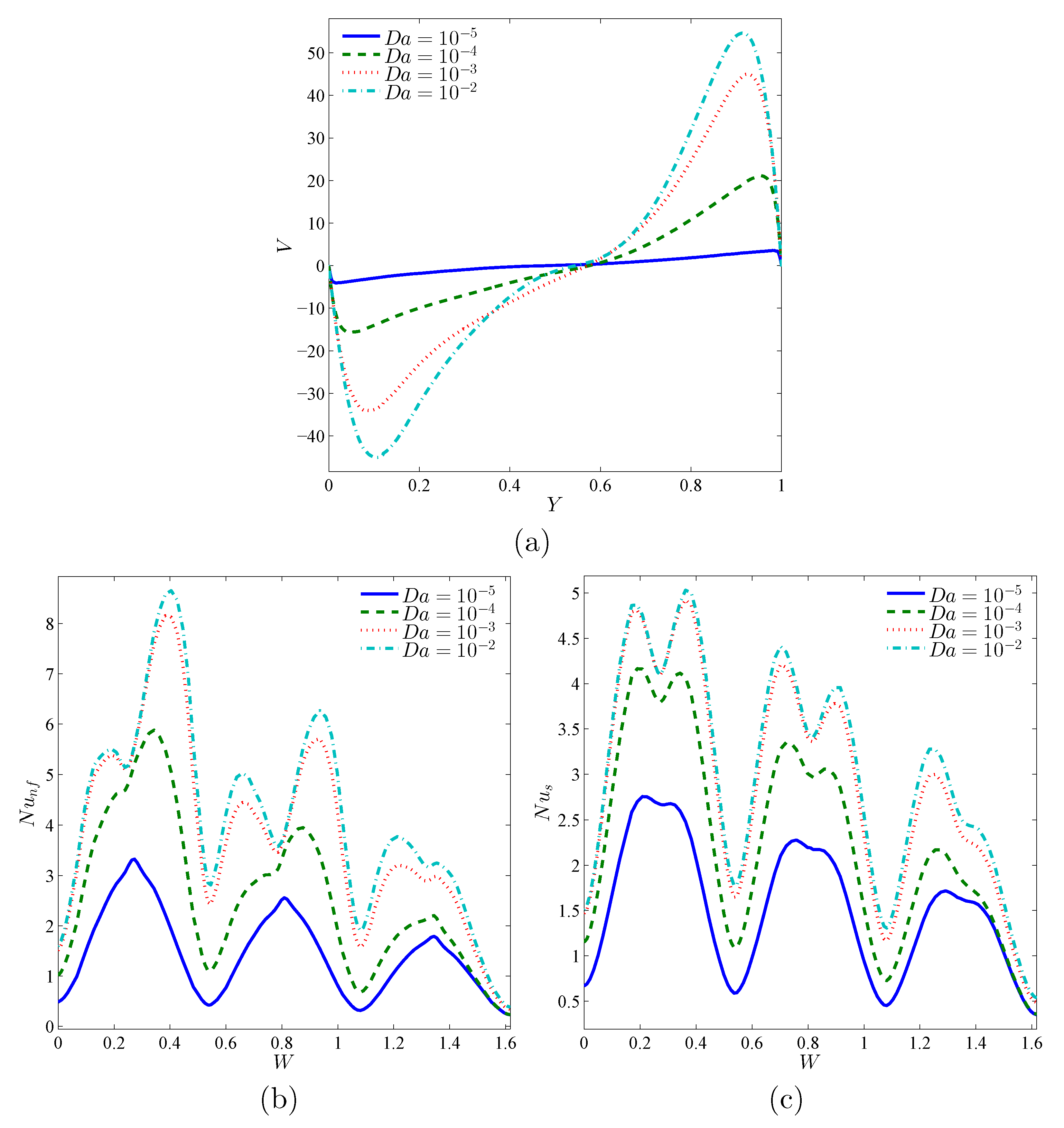
To frame the effect of the porous medium permeability, we present in
Figure 6 the numerical results given by the profiles of the local velocity with the vertical line at
(a), the local Nusselt number of the nanofluid phase (b), and the local Nusselt number of the solid phase (c) for different
for the case of
,
,
, and
. The velocity profiles indicate the rotational aspect of the nanofluid in the cavity. The nanofluids’ circulation rate increases with increasing values of the Darcy number. It is also evident from this figure that the local Nusselt numbers, for both the nanofluid phase and the solid phase, form peaks, and each peak corresponds to a convex boundary of the undulating hot wall. In comparison, the values of the Nusselt number improve by incrementing the Darcy number, and this improvement is more progressive for medium Darcy number levels. It is also worth noting that the heat transfer rate on the lower portion of the wavy wall is bigger than on the top. This is because these regions represent the contact areas for the cold nanofluid returning from the opposite cold wall, so a high temperature difference exists there, which causes a high heat transfer rate.
The differences in the streamlines patterns and isotherms of the nanofluid and solid phases in the different regions with respect to the thermal conductivity ratio in the porous layer (
) when
,
,
, and
are depicted in
Figure 7. For low values of
, the core of the flow vortex is found in the nanofluid layer, indicating the nanofluid circulation strength in this region and its weakness in the porous layer region. This is because most of the heat is transmitted through the solid matrix instead of the nanofluid in the porous layer due to the high value of the solid thermal conductivity. The nanofluid-phase and solid-phase isothermal lines are not similar, indicating the existence of the local thermal non-equilibrium case. When raising the value of
from 0.1 to 1000, the flow vortex expands to cover the porous layer region, and the speed of the circulation strength increases in the porous layer and decreases in the nanofluid layer. It also seems that, as
increases, the system tends to realize the local thermal equilibrium situation in the porous layer, which is observed by the identicalness between the nanofluid-phase isotherms and those of the solid phase.
The local velocity profiles in
Figure 8a show that, for low values of
, the velocity profiles are in conformity because the effect of the solid part is dominant compared to the pore space, which obstructs the buoyancy effects and the flow vortex remains at the center of the cavity. The disparity in the profiles at high
can be explained by the fact that the flow vortex rises up, which results in a low nanofluid velocity at the lower part of the cavity, near the bottom wall.
Figure 8b,c illustrates the impact of the modified thermal conductivity ratio,
, on both the nanofluid-phase and solid-phase local heat transfer rates. Boosting
results in an improvement in the Nusselt numbers. For a weak
, the distribution of
and
differs, which means that the non-thermal equilibrium effects are significant. In addition, it is to note that the impacts of
on the Nusselt numbers are more important for the solid phase than for the nanofluid phase. In fact, the attainment of thermal equilibrium between the nanofluid and the solid matrix leads to a greater heat transfer through the entire porous layer.
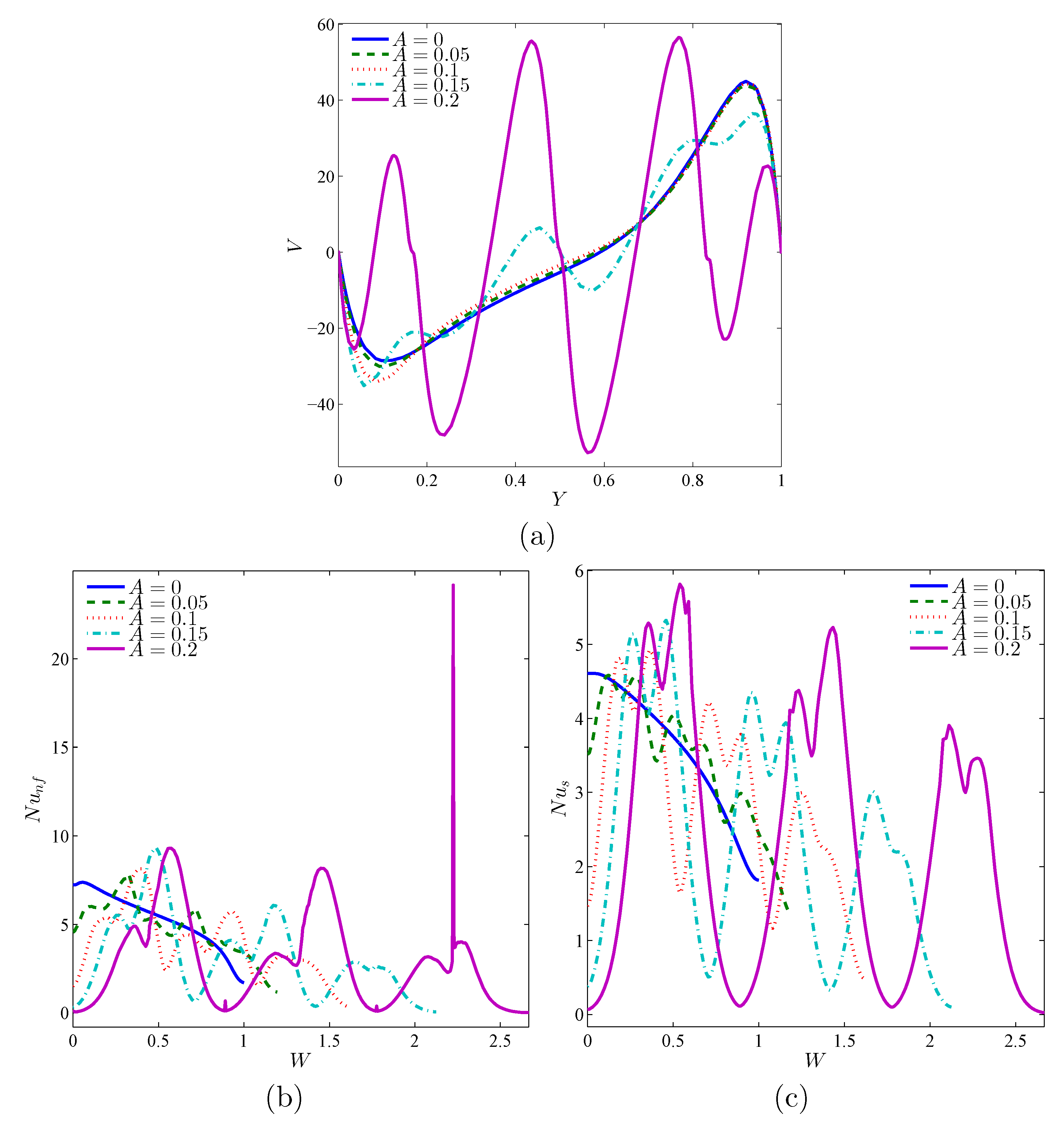
Figure 9 analyzes the effect of the magnitude of the undulations of the solid corrugated wall (
A) on the system’s thermal and dynamic features. Obviously, the larger magnitude undulations, the more conductive the heat transfer tends to be, since the undulations act to impede the nanofluid circulation inside the cavity. The flow configuration switches from one central flow vortex to a multi-core vortex by raising
A, which influences the distribution of the velocity within the cavity (
Figure 10a). Considering the great difference in size and form of the heat exchange surface, the amplitude of the undulations significantly impacts the distribution of the local heat transfer over the hot surface, as seen in the profiles of the Nusselt numbers in
Figure 10c,d.
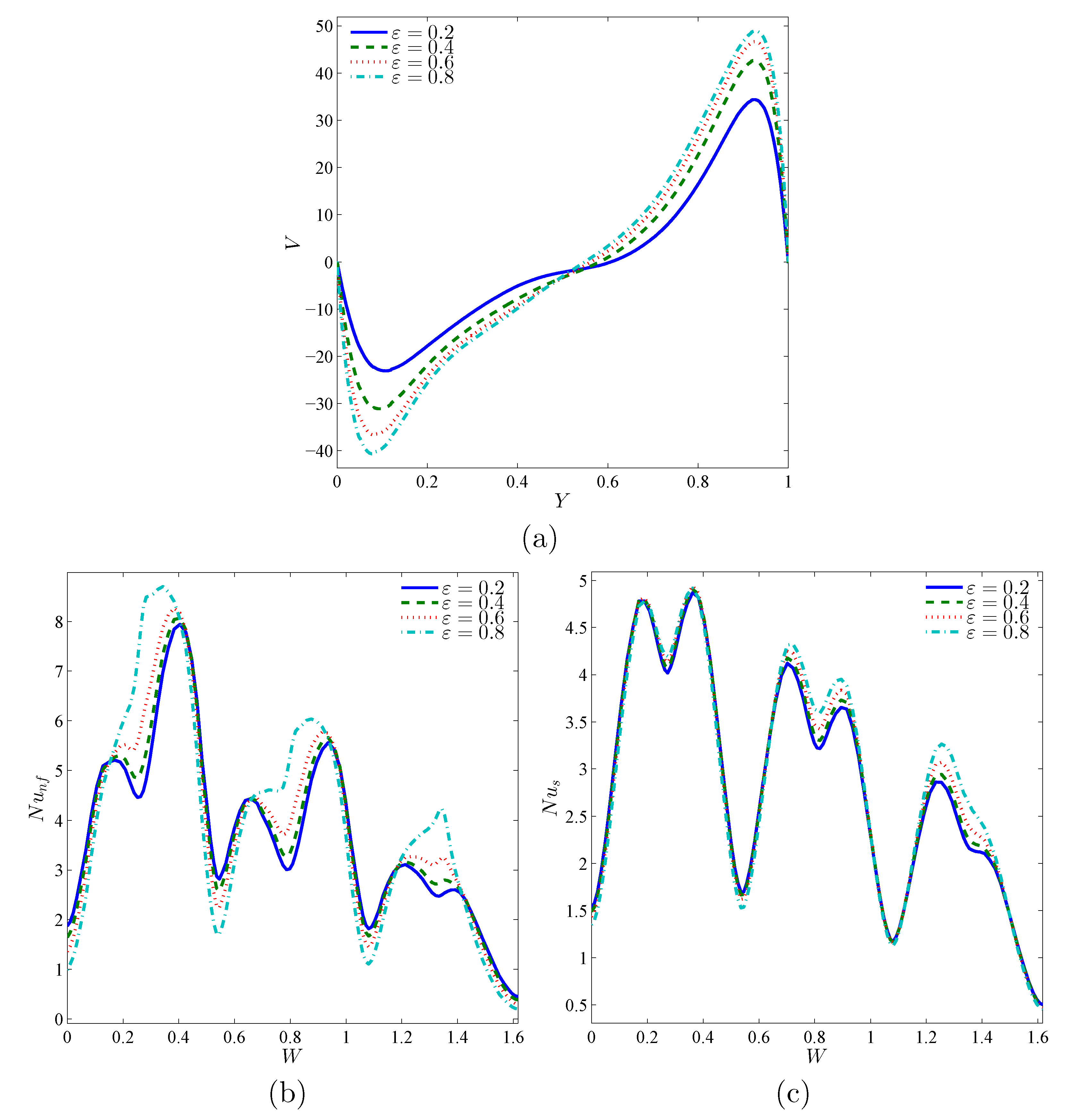
The varying porosity effects of the porous layer (
) on the nanofluid and solid phase isotherms and flow patterns in the different regions inside the cavity are demonstrated in
Figure 11. As can be seen, an increase in the porosity of the porous layer leads to an increase in the nanofluid circulation within the entire cavity. Indeed, as the porosity increases, the nanofluid movement becomes freer in the cavity, which contributes to a greater heat transfer to the nanofluid layer through the porous layer.
Figure 12a indicates that an improvement in the
parameter improves the velocity of circulation as well.
Figure 12b,c shows that the maximum and minimum of the local heat transfer rates of the nanofluid phase are more extreme with a rise of
, whereas the rates of the solid-phase heat transfer are not greatly changed by the variations in the porosity magnitude, as the porous media with a large porosity offers more empty spaces to be occupied with the flowing nanofluid.
The objective of
Figure 13 and
Figure 14 is to show the role of the Darcy number (
) and the modified thermal conductivity ratio (
) at various nanoparticle concentrations (
) in the average heat transport. It is clear that
and
augment the mean Nusselt number of both the nanofluid and the solid phases. The converging values of
and
at lower
values and higher
values indicate the local thermal equilibrium situation, as stated earlier. In addition, it is shown that the increasing effect of
and
on the mean Nusselt numbers reduces when the
and
are higher. Moreover, beyond the value of
, the heat transfer rate decreases with
because the heat transfer through the solid matrix (
) is severely limited due to its low thermal conductivity, unlike
, which continues to increase with
due to the improved nanofluid thermal conductivity. It is also evident from the two figures that increasing the nanoparticles’ concentration produces increases in both Nusselt numbers for all considered values of
and
.
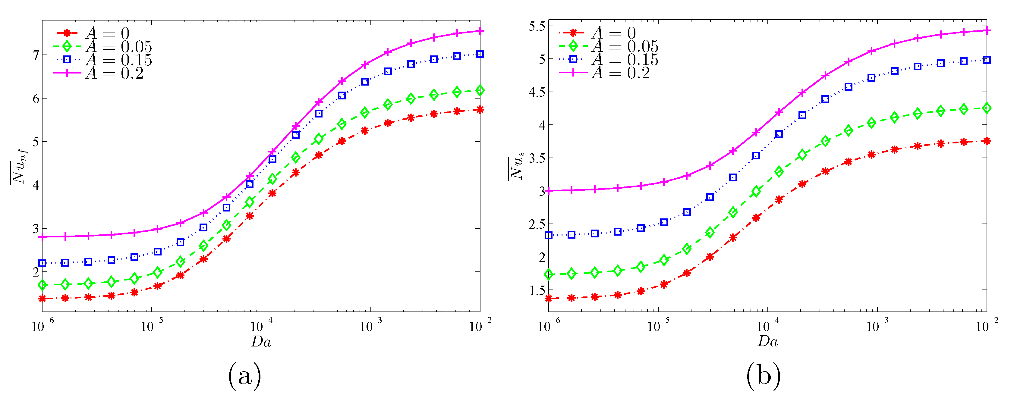
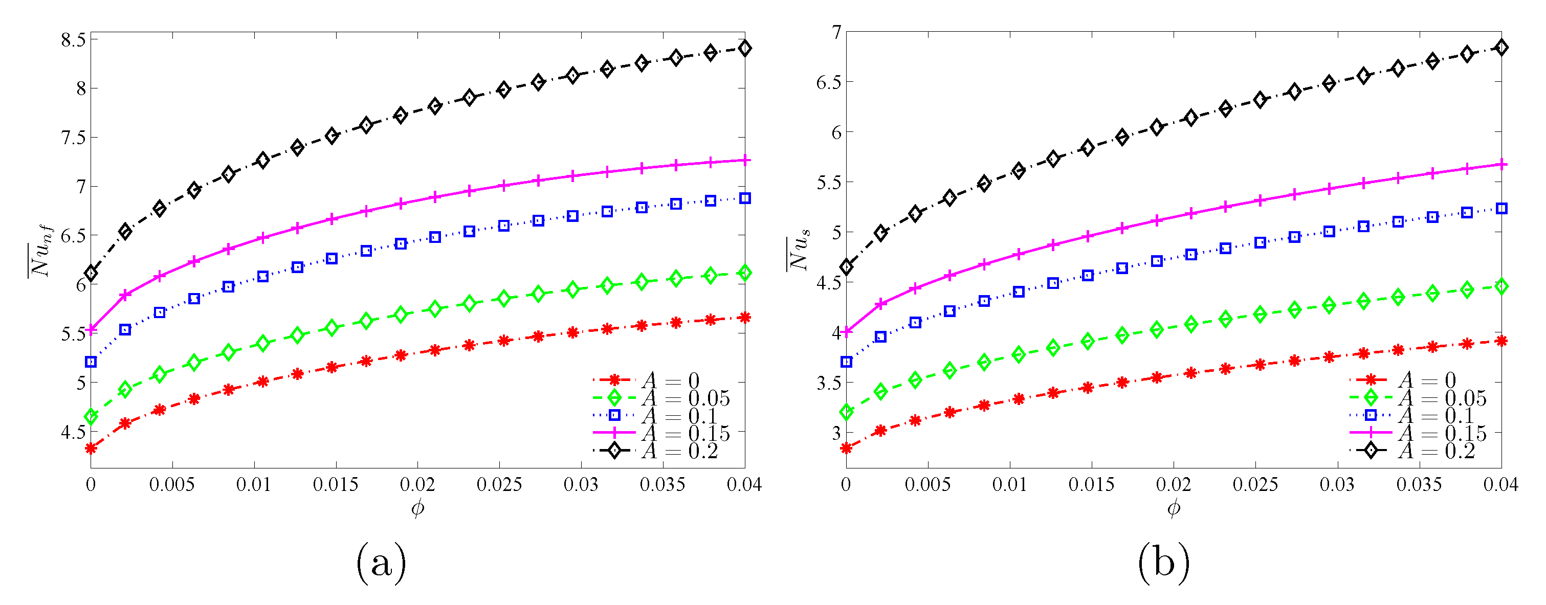
Figure 15 and
Figure 16 show that the largest global heat transfer for both the solid and nanofluid phases is found for the highest undulation amplitude (
) for all tested values of
and
. This can be attributed to the large heat exchange surface of the wavy wall for high values of
A. In addition, at a given
A, the values of the
and
are found to increase with increasing values of
and
.
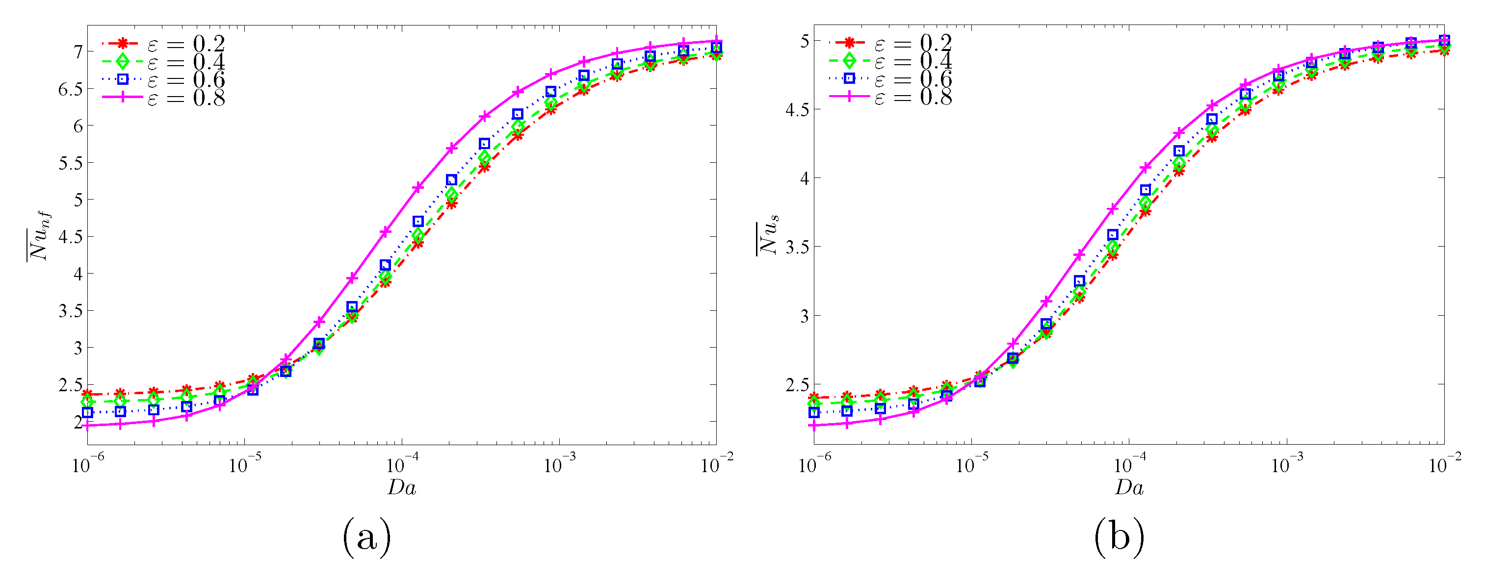
Figure 17 aims to examine the role of the porosity (
) of the porous layer as a function of the Darcy number (
) in the total heat transfer rates of the nanofluid and solid phases for the case of
at
,
, and
. At lower Darcy numbers (
), an increase in the porosity of the porous layer weakens the total heat transfer rates (
and
) owing to the fact that high porosity at low permeability contributes to more heat resistance within the porous medium. The opposite is true for high Darcy numbers.
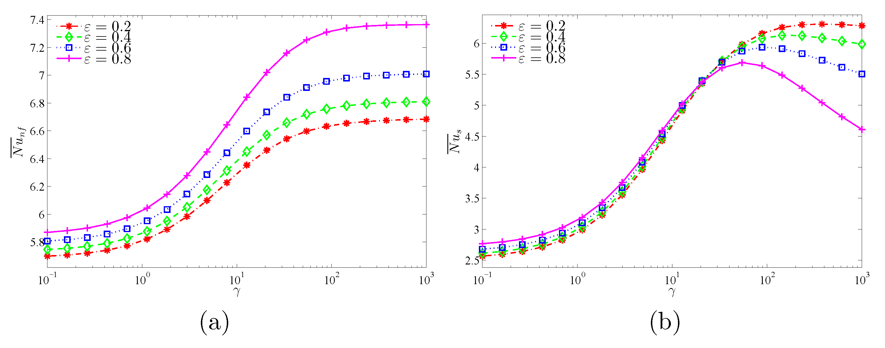
Figure 18 characterizes the variation of
and
with the modified thermal conductivity (
) for various values of
.
increases with the increment of
for all values of
. Meanwhile, there is a limit in the increase of
with
after a certain value of
. This explains that the role of the nanofluid in transferring heat through the porous medium becomes greater than for the solid matrix due to its high thermal conductivity.


 ,
, 


