
Tunable Thermal Camouflage Based on GST Plasmonic Metamaterial


Abstract
:1. Introduction
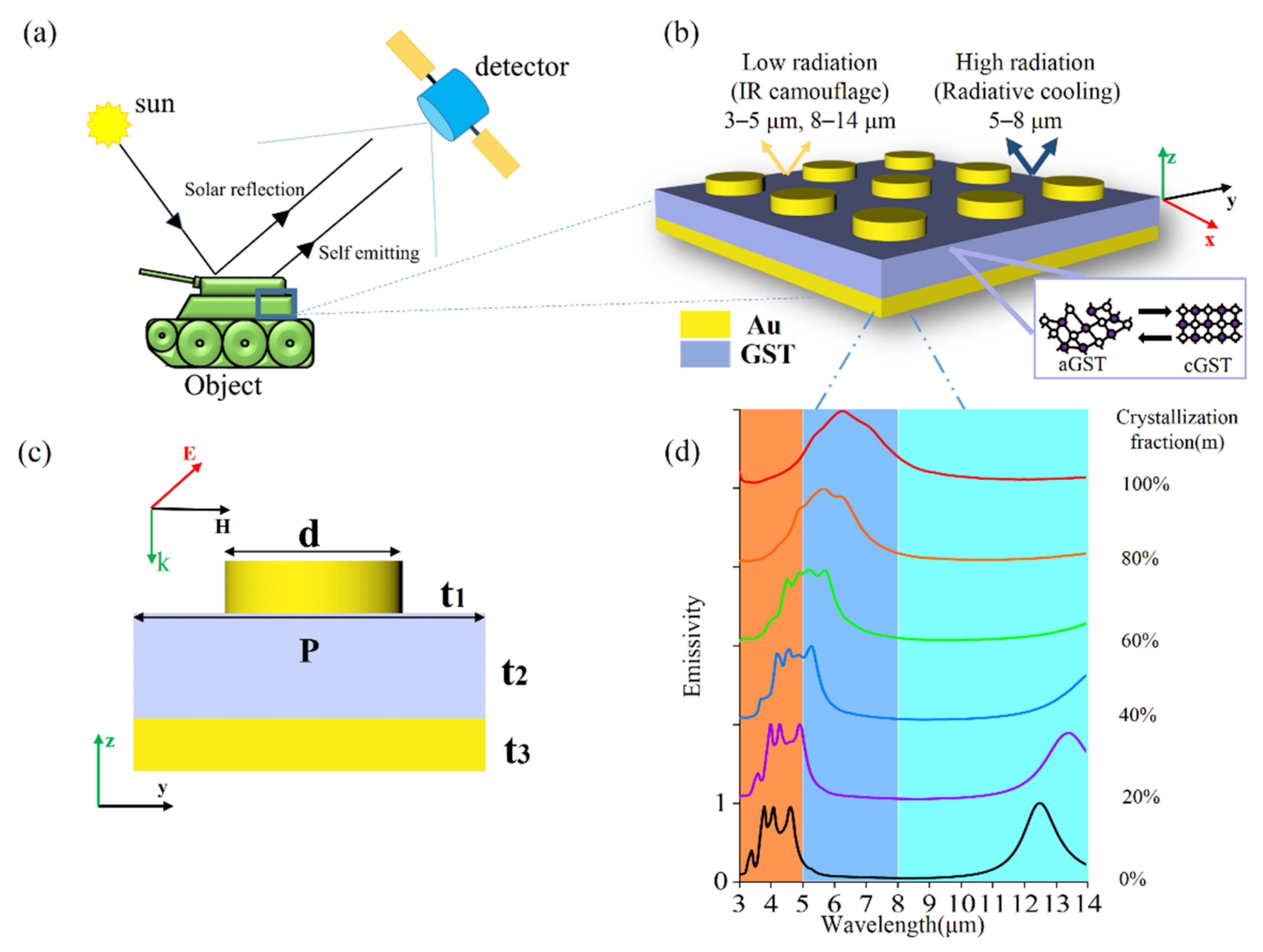
2. Structure Design
3. Physical Mechanism
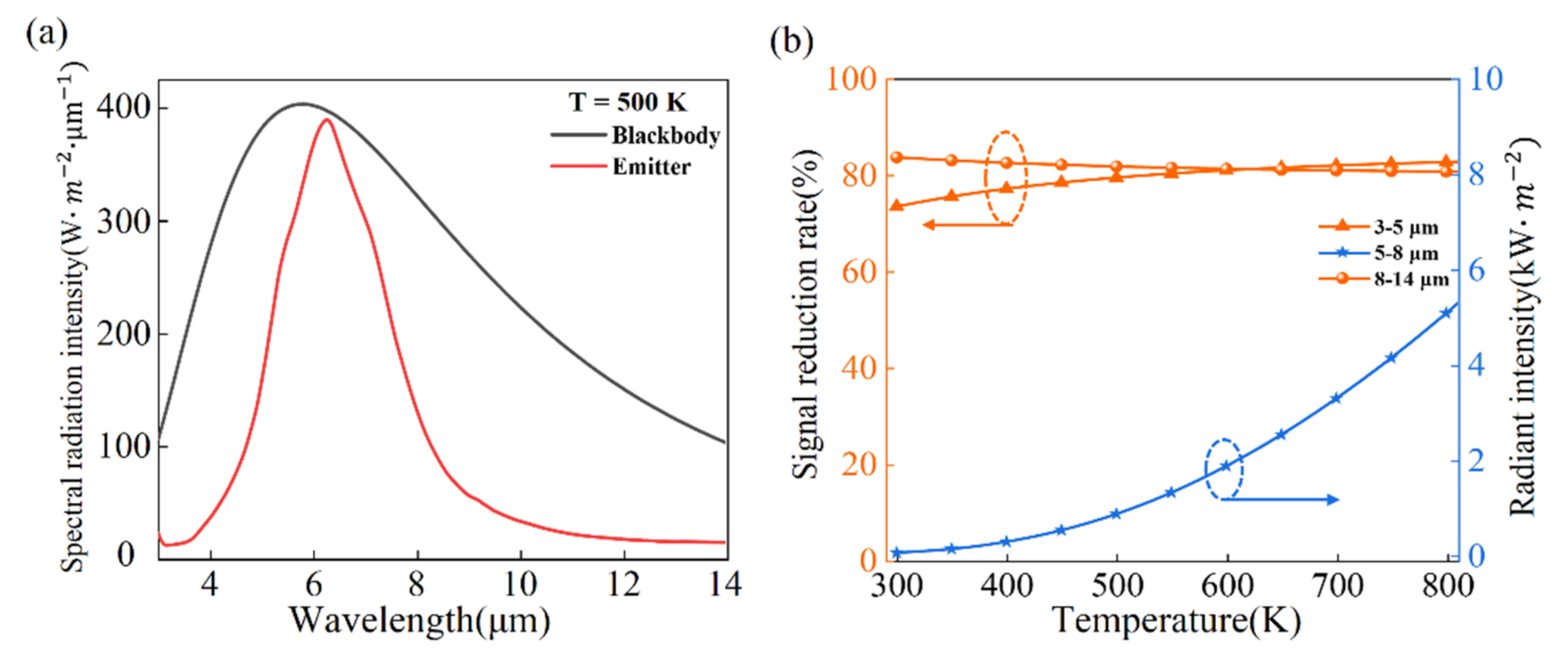
4. Results and Discussions
5. Conclusions
Author Contributions
Funding
Institutional Review Board Statement
Informed Consent Statement
Data Availability Statement
Conflicts of Interest
References
- Raman, A.P.; Anoma, M.A.; Zhu, L.; Rephaeli, E.; Fan, S. Passive radiative cooling below ambient air temperature under direct sunlight. Nature 2014, 515, 540–544. [Google Scholar] [CrossRef] [PubMed]
- Ono, M.; Chen, K.; Li, W.; Fan, S. Self-adaptive radiative cooling based on phase change materials. Opt. Express 2018, 26, A777–A787. [Google Scholar] [CrossRef] [PubMed]
- Wu, S.R.; Lai, K.L.; Wang, C.M. Passive temperature control based on a phase change metasurface. Sci. Rep. 2018, 8, 1–6. [Google Scholar] [CrossRef] [PubMed] [Green Version]
- Costantini, D.; Lefebvre, A.; Coutrot, A.L.; Moldovan-Doyen, I.; Hugonin, J.P.; Boutami, S.; Marquier, F.; Benisty, H.; Greffet, J.J. Plasmonic metasurface for directional and frequency-selective thermal emission. Phys. Rev. Appl. 2015, 4, 014023. [Google Scholar] [CrossRef]
- Raponi, A.; Ciarniello, M.; Capaccioni, F.; Mennella, V.; Filacchione, G.; Vinogradoff, V.; Moroz, L.V.; Rinaldi, G.; Istiqomah, I.; Leyrat, C. Infrared detection of aliphatic organics on a cometary nucleus. Nat. Astron. 2020, 4, 500–505. [Google Scholar] [CrossRef]
- Lenert, A.; Bierman, D.M.; Nam, Y.; Chan, W.R.; Celanović, I.; Soljačić, M.; Wang, E.N. A nanophotonic solar thermophotovoltaic device. Nat. Nanotechnol. 2014, 9, 126–130. [Google Scholar] [CrossRef]
- Seyf, H.R.; Henry, A. Thermophotovoltaics: A potential pathway to high efficiency concentrated solar power. Energy Environ. Sci. 2016, 9, 2654–2665. [Google Scholar] [CrossRef]
- Chen, K.; Santhanam, P.; Fan, S. Suppressing sub-bandgap phonon-polariton heat transfer in near-field thermophotovoltaic devices for waste heat recovery. Appl. Phys. Lett. 2015, 107, 091106. [Google Scholar] [CrossRef] [Green Version]
- Chandra, S.; Franklin, D.; Cozart, J.; Safaei, A.; Chanda, D. Adaptive multispectral infrared camouflage. ACS Photonics 2018, 5, 4513–4519. [Google Scholar] [CrossRef]
- Pan, M.; Huang, Y.; Li, Q.; Luo, H.; Zhu, H.; Kaur, S.; Qiu, M. Multi-band middle-infrared-compatible camouflage with thermal management via simple photonic structures. Nano Energy 2020, 69, 104449. [Google Scholar] [CrossRef]
- Xiao, L.; Ma, H.; Liu, J.; Zhao, W.; Jia, Y.; Zhao, Q.; Liu, K.; Wu, Y.; Wei, Y.; Fan, S.; et al. Fast adaptive thermal camouflage based on flexible VO2/graphene/CNT thin films. Nano Lett. 2015, 15, 8365–8370. [Google Scholar] [CrossRef] [PubMed]
- Dang, S.; Wang, Z.; Ye, H. Optimization and preparation of a visible-infrared compatible stealth film based on D/M/D structure. Mater. Res. Express 2019, 6, 106422. [Google Scholar] [CrossRef]
- Huang, S.; Fan, Q.; Xu, C.; Wang, B.; Wang, J.; Yang, B.; Meng, Z. A visible-light-transparent camouflage-compatible flexible metasurface for infrared-radar stealth applications. J. Phys. D Appl. Phys. 2020, 54, 015001. [Google Scholar] [CrossRef]
- Xia, G.; Kou, W.; Yang, L.; Du, Y.C. Two-dimensional thermal illusion device with arbitrary shape based on complementary media. Chin. Phys. B 2017, 26, 104403. [Google Scholar] [CrossRef]
- Qi, D.; Cheng, Y.; Wang, X.; Wang, F.; Li, B.; Gong, R. Multi-layer composite structure covered polytetrafluoroethylene for visible-infrared-radar spectral Compatibility. J. Phys. D Appl. Phys. 2017, 50, 505108. [Google Scholar] [CrossRef]
- Chen, M.; Morsy, A.M.; Povinelli, M.L. Design of VO2-coated silicon microspheres for thermally-regulating paint. Opt. Express 2019, 27, 21787–21793. [Google Scholar] [CrossRef]
- Zhu, H.; Li, Q.; Zheng, C.; Hong, Y.; Xu, Z.; Wang, H.; Shen, W.; Kaur, S.; Ghosh, P.; Qiu, M. High-temperature infrared camouflage with efficient thermal management. Light Sci. Appl. 2020, 9, 1–8. [Google Scholar] [CrossRef] [Green Version]
- Wang, W.; Guo, C.; Tang, J.; Zhao, Z.; Wang, J.; Sun, J.; Guo, Z. High-efficiency and broadband near-infrared bi-functional metasurface based on rotary different-size silicon nanobricks. Nanomaterials 2019, 9, 1744. [Google Scholar] [CrossRef] [Green Version]
- Wang, W.; Zhao, Z.; Guo, C.; Guo, K.; Guo, Z. Spin-selected Dual-wavelength plasmonic metalenses. Nanomaterials 2019, 9, 761. [Google Scholar] [CrossRef] [Green Version]
- Shen, F.; Kang, Q.L.; Wang, J.; Guo, K.; Zhou, Q.; Guo, Z. Dielectric metasurface-based high-efficiency mid-infrared optical filter. Nanomaterials 2018, 8, 938. [Google Scholar] [CrossRef] [Green Version]
- Guo, Z.; Nie, X.; Shen, F.; Zhou, H.; Zhou, Q.; Gao, J.; Guo, K. Actively tunable terahertz switches based on subwavelength graphene waveguide. Nanomaterials 2018, 8, 665. [Google Scholar] [CrossRef] [PubMed]
- Guo, Z.; Xu, H.; Guo, K.; Shen, F.; Zhou, H.; Zhou, Q.; Yin, Z. High-efficiency visible transmitting polarizations devices based on the GaN metasurface. Nanomaterials 2018, 8, 333. [Google Scholar] [CrossRef] [PubMed] [Green Version]
- Guo, Z.; Li, Z.; Zhang, J.; Guo, K.; Shen, F.; Zhou, Q.; Zhou, H. Review of the functions of Archimedes’ spiral metallic nanostructures. Nanomaterials 2017, 7, 405. [Google Scholar]
- Liu, J.; Ma, W.Z.; Chen, W.; Yu, G.X.; Chen, Y.S.; Deng, X.C.; Yang, C.F. Numerical analysis of an ultra-wideband metamaterial absorber with high absorptivity from visible light to near-infrared. Opt. Express 2020, 28, 23748–23760. [Google Scholar] [CrossRef]
- Guo, Z.; Yang, X.; Shen, F.; Zhou, Q.; Gao, J.; Guo, K. Active-tuning and polarization-independent absorber and sensor in the infrared region based on the phase change material of Ge2Sb2Te5 (GST). Sci. Rep. 2018, 8, 1–8. [Google Scholar] [CrossRef]
- Wu, C.; Fang, Y.; Luo, L.; Guo, K.; Guo, Z. A dynamically tunable and wide-angle terahertz absorber based on graphene-dielectric grating. Mod. Phys. Lett. B 2020, 34, 2050292. [Google Scholar] [CrossRef]
- Qu, Y.; Li, Q.; Du, K.; Cai, L.; Lu, J.; Qiu, M. Dynamic Thermal Emission Control Based on Ultrathin Plasmonic Metamaterials Including Phase-Changing Material GST. Laser Photonics Rev. 2017, 11, 1700091. [Google Scholar] [CrossRef]
- Liu, X.; Tyler, T.; Starr, T.; Starr, A.F.; Jokerst, N.M.; Padilla, W.J. Taming the blackbody with infrared metamaterials as selective thermal emitters. Phys. Rev. Lett. 2011, 107, 045901. [Google Scholar] [CrossRef] [Green Version]
- Zhao, L.; Liu, H.; He, Z.; Dong, S. All-metal frequency-selective absorber/emitter for laser stealth and infrared stealth. Appl. Opt. 2018, 57, 1757–1764. [Google Scholar] [CrossRef]
- Brar, V.W.; Sherrott, M.C.; Jang, M.S.; Kim, S.; Kim, L.; Choi, M.; Sweatlock, L.A.; Atwater, H.A. Electronic modulation of infrared radiation in graphene plasmonic resonators. Nat. Commun. 2015, 6, 1–7. [Google Scholar] [CrossRef]
- Gerislioglu, B.; Bakan, G.; Ahuja, R.; Adam, J.; Mishra, Y.K.; Ahmadivand, A. The role of Ge2Sb2Te5 in enhancing the performance of functional plasmonic devices. Mater. Today Phys. 2020, 12, 100178. [Google Scholar] [CrossRef]
- Bakan, G.; Gerislioglu, B.; Dirisaglik, F.; Jurado, Z.; Sullivan, L.; Dana, A.; Silva, H. Extracting the temperature distribution on a phase-change memory cell during crystallization. J. Appl. Phys. 2016, 120, 164504. [Google Scholar] [CrossRef] [Green Version]
- Ding, X.; Yang, X.; Wang, J.; Guo, K.; Shen, F.; Zhou, H.; Guo, Z. Theoretical analysis and simulation of a tunable mid-infrared filter based on Ge2Sb2Te5 (GST) metasurface. Superlattices Microstruct. 2019, 132, 106169. [Google Scholar] [CrossRef]
- Ding, X.; Kang, Q.; Guo, K.; Guo, Z. Tunable GST metasurfaces for chromatic aberration compensation in the mid-infrared. Opt. Mater. 2020, 109, 110284. [Google Scholar] [CrossRef]
- Salihoglu, O.; Uzlu, H.B.; Yakar, O.; Aas, S.; Balci, O.; Kakenov, N.; Balci, S.; Olcum, S.; Siizer, S.; Kocabas, C. Graphene-based adaptive thermal camouflage. Nano Lett. 2018, 18, 4541–4548. [Google Scholar] [CrossRef] [PubMed]
- Xu, C.; Stiubianu, G.T.; Gorodetsky, A.A. Adaptive infrared-reflecting systems inspired by cephalopods. Science 2018, 359, 1495–1500. [Google Scholar] [CrossRef] [PubMed] [Green Version]
- Qu, Y.; Li, Q.; Cai, L.; Pan, M.; Ghosh, P.; Du, K.; Qiu, M. Thermal camouflage based on the phase-changing material GST. Light Sci. Appl. 2018, 7, 1–10. [Google Scholar] [CrossRef]
- Lu, L.; Dong, W.; Behera, J.K.; Chew, L.; Simpson, R.E. Inter-diffusion of plasmonic metals and phase change materials. J. Mater. Sci. 2019, 54, 2814–2823. [Google Scholar] [CrossRef] [Green Version]
- Palik, E.D. Handbook of Optical Constants of Solids; Academic Press: Cambridge, MA, USA, 1998; Volume 3, pp. 290–295. [Google Scholar]
- Du, K.K.; Li, Q.; Lyu, Y.B.; Ding, J.C.; Lu, Y.; Cheng, Z.Y.; Qiu, M. Control over emissivity of zero-static-power thermal emitters based on phase-changing material GST. Light Sci. Appl. 2017, 6, e16194. [Google Scholar] [CrossRef] [Green Version]
- Voshchinnikov, N.V.; Videen, G.; Henning, T. Effective medium theories for irregular fluffy structures: Aggregation of small particles. Appl. Opt. 2007, 46, 4065–4072. [Google Scholar] [CrossRef]
- Chu, C.H.; Tseng, M.L.; Chen, J.; Wu, P.C.; Chen, Y.H.; Wang, H.C.; Chen, T.Y.; Hsieh, W.T.; Wu, H.J.; Sun, G.; et al. Active dielectric metasurface based on phase-change medium. Laser Photonics Rev. 2016, 10, 986–994. [Google Scholar] [CrossRef]
- Chen, Y.G.; Kao, T.S.; Ng, B.; Li, X.; Luo, X.G.; Luk’Yanchuk, B.; Maier, S.A.; Hong, M.H. Hybrid phase-change plasmonic crystals for active tuning of lattice resonances. Opt. Express 2013, 21, 13691–13698. [Google Scholar] [CrossRef] [PubMed]
- Aspnes, D.E. Local-field effects and effective-medium theory: A microscopic perspective. Am. J. Phys. 1982, 50, 704–709. [Google Scholar] [CrossRef]
- Cengel, Y.A.; Ghajar, A.J. Heat and Mass Transfer: Fundamentals & Applications; Prentice-Hall: Englewood-Cliffs, NJ, USA, 2011. [Google Scholar]
- Lee, N.; Kim, T.; Lim, J.S.; Chang, I.; Cho, H.H. Metamaterial-selective emitter for maximizing infrared camouflage performance with energy dissipation. ACS Appl. Mater. Interfaces 2019, 11, 21250–21257. [Google Scholar] [CrossRef] [PubMed]


Publisher’s Note: MDPI stays neutral with regard to jurisdictional claims in published maps and institutional affiliations. |
© 2021 by the authors. Licensee MDPI, Basel, Switzerland. This article is an open access article distributed under the terms and conditions of the Creative Commons Attribution (CC BY) license (http://creativecommons.org/licenses/by/4.0/).
Share and Cite
Kang, Q.; Li, D.; Guo, K.; Gao, J.; Guo, Z. Tunable Thermal Camouflage Based on GST Plasmonic Metamaterial. Nanomaterials 2021, 11, 260. https://doi.org/10.3390/nano11020260
Kang Q, Li D, Guo K, Gao J, Guo Z. Tunable Thermal Camouflage Based on GST Plasmonic Metamaterial. Nanomaterials. 2021; 11(2):260. https://doi.org/10.3390/nano11020260
Chicago/Turabian StyleKang, Qianlong, Dekui Li, Kai Guo, Jun Gao, and Zhongyi Guo. 2021. "Tunable Thermal Camouflage Based on GST Plasmonic Metamaterial" Nanomaterials 11, no. 2: 260. https://doi.org/10.3390/nano11020260