Article

Towards Multi-Functional SiO2@YAG:Ce Core–Shell Optical Nanoparticles for Solid State Lighting Applications

by
Mahdi Kiani Khouzani
1,
Abbas Bahrami
1,
Maryam Yazdan Mehr
2,*,
Willem Dirk van Driel
2,3 and
Guoqi Zhang
2
1
Department of Materials Engineering, Isfahan University of Technology, Isfahan 84156-83111, Iran
2
Faculty EEMCS, Delft University of Technology, Mekelweg 4, 2628 CD Delft, The Netherlands
3
Signify, High Tech Campus 48, 5600 JW Eindhoven, The Netherlands
*
Author to whom correspondence should be addressed.
Nanomaterials 2020, 10(1), 153; https://doi.org/10.3390/nano10010153
Submission received: 15 December 2019 / Revised: 10 January 2020 / Accepted: 11 January 2020 / Published: 16 January 2020
(This article belongs to the Special Issue Luminescent Nanomaterials)

Abstract

:
This paper aims to investigate the synthesis, structure, and optical properties of SiO2@YAG:Ce core–shell optical nanoparticles for solid state lighting applications. YAG:Ce phosphor is a key part in white light emitting diodes (LEDs), with its main functionality being the generation of yellow light. Generated yellow light from phosphor will be combined with blue light, emitted from chip, resulting in the generation of white light. Generated light in LEDs will often be scattered by SiO2 nanoparticles. SiO2 nanoparticles are often distributed within the optical window, aiming for a more homogeneous light output. The main idea in this research is to combine these functionalities in one core–shell particle, with its core being SiO2 and its shell being phosphor. In this study core–shell nanoparticles with different Ce3+ concentrations were synthesized by a sol–gel method. Synthesized nanoparticles were characterized by X-ray diffraction (XRD), small angle X-ray scattering (SAXS) analysis, high resolution transmission electron macroscopy (HRTEM), Fourier transform infrared (FTIR), and photoluminescence spectroscopy. Luminescence characteristics of SiO2@YAG:Ce core–shell particles were compared with that of SiO2/YAG:Ce mixture composite, which is now used in commercial LEDs. Obtained results showed that core–shell nanoparticles have comparatively much better optical properties, compared to SiO2/YAG:Ce mixture composite and can therefore be potentially used in LEDs.

Graphical Abstract

1. Introduction

Light converting phosphors have a significant contribution in many photonic and optoelectronic devices and components [1,2,3,4,5]. Amongst different phosphors, yttrium aluminum garnets (Y3Al5O12: YAG), doped with rare-earth elements, i.e., Ce3+, are considered as one of the most widely used photonic materials [6] YAG:Ce phosphors have unique optical properties, making them excellent choices for different applications, ranging from lasers to solid state lighting sources [7,8,9,10]. This includes cathode-ray tubes (CRT), field emission displays (FED), scintillators, plasma display panels (PDP), electroluminescent displays, and light emitting diodes (LED). One of the most important characteristics of YAG:Ce phosphor is its ability in converting blue light radiation into a very wide band yellow emission. In LEDs, for instance, YAG:Ce phosphor absorbs the blue light and radiates yellow light. Generated yellow light will then be combined with non-absorbed blue light, resulting in the final emission of white light in LEDs [11]. This is schematically depicted in Figure 1. Currently, phosphor-based white LEDs are gaining significant attention because of their advantages over existing incandescent and halogen lamps such as their higher reliability, lower energy consumptions, and higher light output [7]. According to the US Department of Energy (DOE) report, LEDs are expected to represent 84% of lumen-hour sales for general illumination products by 2030 [12]. Based on the current state of technology, the report predicts that a 40% reduction in energy consumption in the lighting sector can be attained by 2030, if traditional light sources are replaced with LEDs [12]. Predicted energy savings are mostly in linear fixture, low/high bays, and outdoor applications. Overall, it appears that LEDs will have a prominent contribution to energy consumptions and energy savings in the lighting industry. In solid state lighting applications, and more specifically in LEDs, YAG phosphor particles play a vital role. The efficiency of an LED is directly linked to the light conversion efficiency of phosphors. In order to achieve a higher luminous efficiency and color homogeneity in LEDs, the so-called scattering enhancement particles (SEP), such as SiO2, TiO2, CaF2, and CaCO3 are routinely added to LED lens [13,14,15,16] (see Figure 1). Scattering agents are often mixed with phosphor particles, and the mixture composite, together with other additives, are added to the plastic lens. In this case, phosphor particles have optical functionality, while scattering agents obviously scatter the light to improve the color homogeneity of emitted light [14,17,18,19]. This paper investigates the idea of combining these functionalities in one multi-functional core–shell nanoparticle in which the shell is a phosphor layer and the core is the scattering agent. Luminescent core–shell structures appear to be very promising and are now becoming more popular in different applications [20,21,22,23,24,25,26]. Core–shell nanostructures show superior physical and chemical properties in comparison with their single-component counterparts, making them attractive choices for a wide range of applications not only in solid state lighting, but also in biomedicine, energy conversion, storage, and catalysis. In core–shell structures, shell often protects the core from the working environment, adds new chemical or physical capabilities to the core, maintains structural integrity, limits volume expansion, and inhibits particle aggregations [27,28]. Amongst different scattering agents in LEDs, silica is the most widely used one, due to the ease of synthesis, great controllability over the size, and structural stability. The focus in this study is to synthesize SiO2@YAG:Ce nanoparticles, using a sol–gel process, and to evaluate their optical properties. The aim is to achieve perfect spherical shaped core–shell particles, with the core being SiO2 and the shell being a homogenous thin phosphor shell. This ultimately ends up in multi-functional particles, which simultaneously generate and scatter light.

2. Materials and Methods

2.1. Synthesis of Core–Shell SiO2@YAG:Ce Nanoparticles

SiO2@YAG:Ce nanoparticles doped with 0.25, 0.5, 1, and 2 atomic weight % Ce were prepared by the sol–gel method [29,30,31,32]. Pure Y(NO3)3·6H2O (Sigma-Aldrich, St. Louis, MO, USA), Al(NO3)3·9H2O (Sigma-Aldrich, St. Louis, MO, USA), and Ce(NO3)3·6H2O (Sigma-Aldrich, St. Louis, MO, USA) were used as the cations’ sources. In the first stage, the nitrate salts were mixed in stoichiometric ratios (at a molar ratio Y:Al of 3:5) and dissolved in deionized water and citric acid (Merck, Darmstadt, Germany), such a way that the molar ratio CA:M3+ is 1:1 (M3+ = Y3+ + Al3+ + Ce3+). The solution was magnetically stirred until a clear solution was obtained. Then, ethylene glycol (Merck, Darmstadt, Germany), which acts as a polymerization agent, was added to the solution and the solution was heated with stirring at 80 °C for 30 min. pH was constantly monitored and kept at 3 by dropwise addition of NH3 solution (Merck, Darmstadt, Germany). Effects of variation in the pH between 3 and 4 on the structure of synthesized phosphor was also studied. In the second stage, SiO2 nanoparticles and polyethylene glycol (PEG; 10000-PEG, Merck, Darmstadt, Germany) as surfactant [20,22], were dispersed in deionized water. The SiO2/PEG-containing solution was added to the primary solution, while the solution was magnetically stirred. Figure 2 shows the X-ray diffraction (XRD) spectrum and FESEM image of SiO2 nanoparticles with mean particle size of 25 nm. SiO2 particles are spherical with a perfectly narrow size distribution. XRD spectrum also showed that SiO2 has an amorphous structure. To obtain core–shell nanopowders, the solution was further heated at 80 °C (for about 1.5 h) until it turned into a gel. The obtained gel was then dried at about 120 °C for one day, followed by calcination at 1000 °C for 1, 2.5, 5, and 10 h. An overview of the whole synthesis process is shown in Figure 3. In order to investigate the effects of shell thickness on the optical properties of nanoparticles, this process was conducted twice for some samples, hereafter named coat II. Samples, named coat I, are those that are coated one time. Optical properties of core–shell particles were compared with SiO2/YAG:Ce composite mixture (which is made of mixing SiO2 and YAG:Ce particles). This mixture powder is now currently used in the LED industry.

2.2. Characterization of Core–Shell Nanoparticles

The crystal structures of as-prepared SiO2@YAG:Ce core–shell and Y3Al5O12 phosphor particles were evaluated by X-ray diffraction (XRD) with CuKα radiation (λ = 1.54 Å). Small angle X-ray diffraction (SAXS) analysis was also carried out at ESRF in Grenoble to study the structural properties and mean shell thickness in synthesized core–shell powders under various reaction conditions. The powders were supported by an adhesive tape. The scattering intensity I(q) was measured as a function of q = 4π/λ sin θ, with being the scattering angle and λ = 0.154 nm being the wavelength of the used radiation. The surface morphology, the particle size and shape were analyzed with field emission scanning electron microscope (FESEM) and transmissions electron microscope (TEM/high resolution transmission electron macroscopy—HRTEM) (Tecnai 200STEM-FEG, FEI The Netherlands). Fourier transform infrared (FTIR) analyses were done by a Perkin Elmer Spectrometer (PerkinElmer, Waltham, MA, USA). Photoluminescence spectroscopy was carried out, using Avaspec 2048 TEC (Avantes, Apeldoorn, the Netherlands). Diffuse transmission spectra of core–shell particles were also measured.

3. Results and Discussion

3.1. Analyses of Synthesized Phosphor Particles

The XRD patterns of as-prepared phosphor powders, synthesized at different pH values and calcined at 1000 °C for 4 h, are shown in Figure 4. It appeared that the outcome of the synthesis was largely dependent on the pH values. The optimum synthesis condition was achieved when pH is strictly controlled at 3. Any deviation from pH = 3 towards higher values, and more specifically towards 3.5–4.0 pH range results in the appearance of YAM (Y4Al2O9) and YAP (YAlO3) transitional phases in as-synthesized powders. Figure 4 shows clear difference between XRD patterns of phosphor powders, synthesized at pH = 3 and that synthesized at pH range 3.5–4. Boukerika et al. [32] reported that pure cubic YAG phase with optimum optical properties can be attained at pH ≤4. It is reported that in case of pH ≥ 6, the formation of unfavorable phases such as Y4Al2O9 (YAM) and YAlO3 (YAP) is inevitable. The finding in this study is rather different with what is reported by Boukerika et al. [32], as the pure YAG was found out to be obtainable at pH ≤ 3. This possibly has to do with the fact that different raw materials are used in these studies. Both YAM and YAP phases are considered as impurities in YAG, as they cause energy level splitting of luminescence centers. This obviously adversely affects optical properties of phosphor. Overall, pH appears to be the most crucial controlling factor when it comes to the final phase composition of synthesized powders. Obtaining a pure homogenous phosphor phase is only possible when pH is strictly controlled. As mentioned earlier, the pH in this case was kept at 3 by dropwise addition of NH3 solution. Figure 4b also shows FESEM image of synthesized YAG:Ce powders. It is clear that synthesis has resulted in nanoparticles with spherical morphology with a perfectly homogenous dispersion. Elemental mapping of a synthesized YAG:Ce particle, depicted in Figure 5, shows that elements are also perfectly homogeneously distributed.
Figure 6a shows an example of the XRD pattern of samples annealed at 1000 °C. All peaks in the XRD patterns perfectly match with those of cubic YAG (JCPDS Card No. 79-1891) and no other crystalline phase such as YAlO3 (YAP) or Y4Al12O9 (YAM) can be detected. To make sure that synthesized YAG also has a structure, similar to that of industrial YAG, XRD spectra of synthesized and commercial YAG samples were compared (see Figure 6a). As mentioned earlier, single-phase pure YAG is very important in the luminescence efficiency of synthesized powders. Existing dopants obviously do not alter the structure of crystalline YAG. However, they surely change lattice parameters owing to the inequality of ionic radii between substituted yttrium ion and the dopant. A detailed XRD study on the effect of annealing time on the formation of YAG phase in core–shell nanoparticles was carried out. Figure 6b shows XRD patterns of SiO2@YAG:Ce nanoparticles after annealing from 1 to 10 h. The YAG phase starts to form after 1 h of annealing at 1000 °C. Therefore, one can conclude that crystallization time can be effectively decreased through the sol–gel method. In this work the minimum required crystallization time was found to be 1 h at 1000 °C. Appearance of sharp peaks and increasing the intensity of the main peak (2θ = 33.4, related to the crystallographic plane with Miller indices of {4 2 0}) is an indication of crystallization during annealing. The intensity of diffraction peaks of SiO2@YAG:Ce sample slightly increases with increase in the calcination time, inferring that the degree of crystallinity has increased. Meanwhile, this also indicates that mean crystallite size increases with increase in annealing temperature [30,31]. The same is expected when the annealing temperature is increased. Figure 6c shows schematic view of crystal structure of YAG, showing that YAG has a cubic garnet structure, containing octahedra (AlO6), tetrahedra (AlO4), and dodecahedra (YO8) with corner-shared O atoms. The co-doped Ce3+ ion as luminescence centers substitutes for Y3+ ion that is located in the position of YAG dodecahedral.

3.2. SAXS Analyses

Obtained SAXS data are presented in a log–log plot. SAXS curves are essentially plots of intensity as a function of the scattering vector q, which corresponds to the scattering angle , given by [34]:
q = ( 4 π λ ) × sin θ .
The measured SAXS data were modeled using a commonly named global unified fit model [35,36]. In fact, this model includes a power-law regime in order to describe the mass or surface fractal and a Guinier regime to characterize the mean structural size, given by:
I ( q ) = i = 1 n [ G i exp ( q 2 R g i 2 / 3 ) + B i exp ( q 2 R g ( i + 1 ) 2 / 3 ) × { q [ erf ( q R g i 6 ) ] 3 } P i ] ,
where, Rgi is the radius of gyration, erf is error function, i refers to the differently sized structures, Gi is the Guinier pre-factor, and Bi is the pre-factor specific to the power-law scattering with an exponent Pi. The mean primary particle size dp (for spherical particles) can be estimated from the radius of gyration Rg, which can be obtained by Guinier’s law [35]:
d P = 2 5 3 × R g .
In case nanoparticles have a log-normal size distribution, in order to characterize the particle size distribution from the SAXS data, three fitting parameters, Rg, G, and B are often used. The geometric standard deviation (σg) in this case is given by [36]:
σ g = exp ( ln [ B × R g 4 1.62 G ] 12 ) ,
which characterizes the width of the size distribution. In the scattering vector q region, the scattering intensity I(q) can be characterized by the so-called power law [37]:
I ( q ) = B × q p ,
where B is the power-law pre-factor and P refers to the power-law exponent. From the log I(q) versus log q curves and slopes of linear region (at large values of scattering vector q), the values of the exponent P can be measured. In order to study particle surface characteristics like roughness, the surface-fractal dimension or ds (ds = 6 − P) is often used [36,37]. This is in particular useful for ideal two-phase structure with smooth surfaces and sharp boundaries.
In order to determine the effective thickness of boundary layer along the radial direction of the sphere, the following formula is suggested [38,39]:
E = 2 3 σ ,
where σ is the standard deviation of the Gaussian smoothing function and E is the thickness of the diffuse boundary layer, which can be measured by [38]:
I ( q ) K p × q 4 × ( 1 q 2 E 2 / 12 ) .
Figure 7a shows the scattering curves I(q) measured for pure SiO2 and SiO2@YAG:Ce core–shell nanoparticles. Before the coating was applied, the measured SAXS curve of un-coated SiO2 did not exhibit any specific side maxima. In order to extract structural information from the spectra, the data of the pure SiO2 were fitted by Guinier law (Equation (2)), the measured radius of gyration for primary particle of SiO2 (RG,P) was 8.9 nm (dp = 22.97 nm, σg = 1.34), which is in accordance with TEM images. The power-law fit in the high of scattering vector q region follows Porod’s law, i.e., Iq−3.67, implying that these silica nanoparticles have almost smooth surfaces (surface fractals or Ds = 2.33). After preparation of core–shell nanoparticles, a specific side maximum or a shoulder appears in SAXS spectra (highlighted with red arrow). On the other hand, the coating process resulted in the formation of a YAG:Ce shell, growing on the SiO2 particle surface gradationally by heterogeneous nucleation. Similar side maximum or shoulders have been reported in the literature as particle−particle interactions (structure factor) [40,41,42,43]. In SiO2@YAG:Ce with two times coating (coat II), the progressive growth of shell is more visible in the SAXS in which the shoulder or specific side maximum is more clear (Figure 7b), suggesting that the shell grows with time. So, the YAG:Ce shell becomes thicker and the side maximum or shoulder is shifted to smaller scattering vector q region. In order to calculate the shell thickness, the SAXS data of the pure SiO2@YAG:Ce (coat I and II) were fitted by Equation (7), as displayed in Figure 7a and Figure 6b. The calculated mean thicknesses of the diffuse and formed interfacial boundary nanostructured layer of one and two cycle coating are 2.8 nm and 7.7 nm, respectively. The stability of SiO2@YAG:Ce core–shell nanoparticles at 1000 °C for different time was investigated by heating the sample from 1 to 10 hours in air. Figure 8 shows SAXS measurement of SiO2@YAG:Ce nanoparticles, calcined at 1000 °C for different times. It is noticeable that SAXS curves for all the specimens is almost similar, inferring that after calcination the core–shell structure of SiO2@YAG:Ce nanoparticles was perfectly preserved. Even heating the sample up to 10 h hardly results in any change in the morphology of nanoparticles, inferring that SiO2 cores are still encaged within the YAG:Ce shells. This obviously shows high thermal stability of SiO2@YAG:Ce core–shell nanoparticles [44,45]. It is noteworthy that the exponent of power-law fit at large q is greater than four (for example, I ∼ q−4.20), inferring that there exists a sprayed and formed boundary nanostructure like a thin layer formed on the particle surface of SiO2.

3.3. HRTEM/TEM Observations
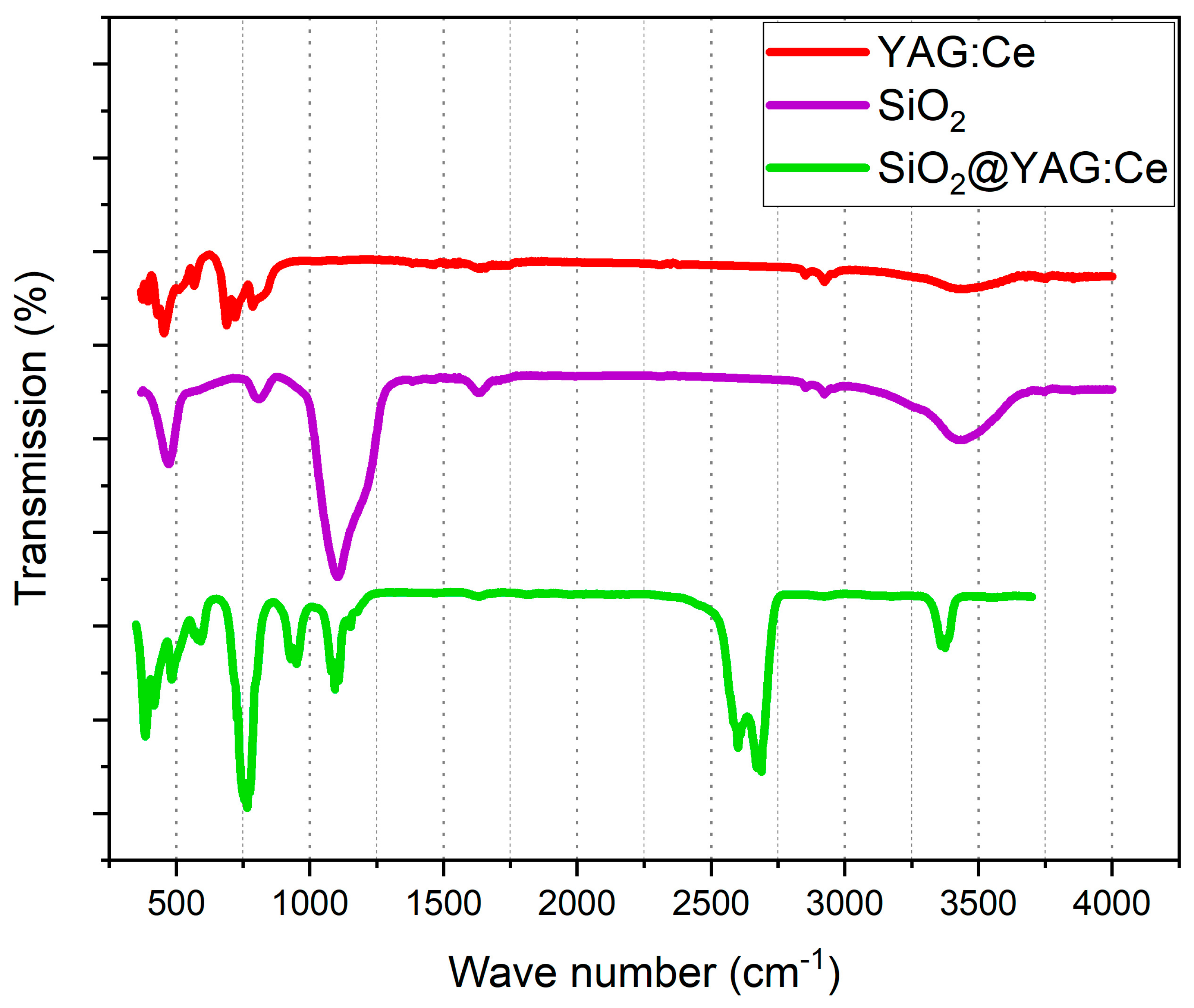
HRTEM observations show that a relatively homogeneous thin layer of YAG:Ce has formed on the surface of the SiO2 particles (see Figure 9a). The size of this thin outer shell on the surface of particles was measured to be approximately 3 nm for one cycle coating, which is in a perfect agreement with SAXS calculations. Figure 9b shows TEM image of a single nanosphere after applying second layer of YAG:Ce coating. As can be seen, the thickness of the shell has increased from 3 to 7 nm. So, overall the thickness of the shell after one cycle coating was ∼3 nm and that increases to ∼7 nm after second cycle of coating. This is again in a good agreement with SAXS measurements. Figure 9c shows elemental mapping of alloying elements in synthesized particles. Elements are clearly homogeneously distributed in synthesized particles, inferring that YAG has been successfully synthesized on silica particles.

3.4. FTIR Analyses

Fourier transform infrared (FTIR) spectroscopy was used to study changes in the chemical structure of samples during synthesis (see Figure 10). Infrared spectra were recorded using a Perkin–Elmer Spectrum 100 series spectrometer in the attenuated total reflection (ATR) mode for 200 scans at a resolution of 4 cm−1. In the spectrum related to the SiO2 particles, the absorption bands due to OH (3435 cm−1), Si–O–Si (801 cm−1), Si–OH (950 cm−1), and SiO (471 cm−1) bonds were observed. Abovementioned absorption peaks show that SiO2 particles contain a large amounts of hydroxide (OH) groups and water (H2O) on the surface [46]. The SiOH groups play a very significant role for bonding the ions to the YAG:Ce shell. The FTIR spectrum, related to pure YAG:Ce powders, shows a strong absorption peak at 800 cm−1 and a weak peak at 455 cm−1, which are attributable to the absorption of AlO and YO bonds, respectively [32]. The dopant presence can also be confirmed by the peak at 516 cm−1, which is attributable to the vibration mode of the Ce–O bond. For the SiO2@YAG:Ce core–shell sample, the characteristic absorption peaks of the AlO bond (788 cm−1) for YAG:Ce and the Si–O–Si bond (1055 cm−1) for amorphous SiO2 are clearly visible. It appears that the weak signal of AlO bond has been affected and covered by the bending vibration of SiO bond at 471 cm−1. FTIR results are also in a perfect match with the XRD, HRTEM, and SAXS analyses, again confirming the formation of a crystallized YAG:Ce coatings on the silica surface via the sol–gel deposition.

3.5. Photoluminescence (PL) and Diffuse Transmission Spectra (DTS) Analyses

The photoluminescence (PL) spectra of YAG:Ce-coated silica nanoparticles as well as that of commercial and synthesized SiO2/YAG:Ce mixture samples are shown in Figure 11a. The emission spectra consist of a typical broad emission band centered at 540 nm and a shoulder at longer wavelength side. The former is assigned to the 5d1 → 2f5/2 and the latter to the 5d1 → 2f7/2 transition in Ce3+. The broad band spread from 500 to 650 nm is an ideal yellow light emission, which is in association with blue light emitted by InGaN LED chips. It is known that Ce3+ ion with a 4f1 electron configuration has two ground states of 2f5/2 and 2f7/2 owing to the spin-orbit coupling [47]. It is also noticeable that peak positions of YAG:Ce samples are not affected by SiO2 nanoparticle. The observed peak is due to characteristic transition of Ce3+. The fact that peak position is not changed in core–shell samples infers that the presence of SiO2 as the core hardly affects the structure and luminescence properties of YAG:Ce phosphor. Figure 11a also depicts that the higher the thickness of YAG:Ce shell, the higher is the maximum intensity in the PL spectrum. As can be seen, SiO2@YAG:Ce (1.0 at.% Ce) nanoparticles show the highest emission, compared to commercial and synthesized SiO2/YAG:Ce mixture composite, that is in agreement with similar works in this field [20,21,22,48,49,50,51]. The increased PL intensity of YAG:Ce in the core–shell state is believed to result from the inhibition of surface states in YAG:Ce nanoparticles and the higher light extraction at the SiO2/YAG:Ce interface. Emission intensity improvement of core–shell nanoparticles can also be attributed to the fact that a significant amount of non-radiative centers exist on the surface of core SiO2 are decreased by the coating effect of the YAG:Ce shell (as a shielding layer). Obviously, the surface –OH groups play a crucial role in the PL quenching. Surface elimination of –OH groups due to the surface coating originates from hydrogen bonds on the surface of SiO2 (see Figure 10). This will certainly influence the radiative relaxation pathway. Overall, it appears that using SiO2 nanoparticle as cores significantly enhances the emission intensities of core–shell particles due to light absorption/scattering by coated nanoparticle [20]. The number of coating cycles plays a vital role in enhancing the PL intensity of the core–shell particles (Figure 11a). The increase in the PL intensity with double coating cycle is obviously attributable to the increase in the thickness YAG:Ce shell on the SiO2 cores, which in turn increases emitting ions (Ce3+) per core–shell particle [22]. Figure 11b shows the effects of Ce content on the emission peak intensity of SiO2@YAG:Ce nanoparticles. SiO2@YAG:Ce nanoparticles show the highest emission when doped with 1.0 at.% Ce, compared with SiO2/YAG:Ce (commercial and synthesized mixture composite), which is in agreement with previous investigations [30,52,53,54]. The enhancement of PL intensity with an increase in Ce3+ concentration is due to the efficient incorporation of Ce as luminescence centers into the host material; in this case being YAG. The luminescent intensity is to a large extent affected by the average distance between luminescent centers. The distance among luminescence centers or active ions decreases due to increase in the concentration of doped ion to values more than 1.0 at.%. Further increase in Ce3+ dopant concentration results in an increase in the unit cell parameters, which may in turn enlarge the distance between Ce3+ ions in the YAG:Ce structure. More non-radiation can also be the result of cross relaxation of the excessive dopant (Ce3+ ions). Given that the ionic radius of cerium is approximately 17.5% larger than that of yttrium ion, the substitution of Ce3+ ion to Y3+ sites is rather difficult. The excessive doping hinders the substitution of Y3+ with Ce3+ ions. Thus, the incorporation of high concentration of Ce3+ shortens the average distance between Ce3+ and non-radiative transitions possibility increases, which leads to the concentration quenching of Ce3+ ions [53,54]. The other reason for the reduction of emission intensities of YAG with high Ce3+ concentration is the sectional absorption of excitation photons by YAG as host material. This induces less excitation of Ce3+ ion and thus the PL intensity of the YAG:Ce phosphors is lowered [53]. At last, cerium ion oxidation (Ce3+ → Ce4+), i.e., CeO2, which expectedly takes place close to the surface can decrease the photoluminescence intensity of the Ce3+ luminescence centers [54]. In order to avoid abovementioned problems and achieve the highest brightness and efficiency in YAG with Ce as luminescence centers, achieving a homogeneous distribution of Ce3+ ions in the YAG host is extremely important. It appears that synthesized SiO2@YAG:Ce core–shell particles have a comparatively higher PL intensity, compared to SiO2/YAG:Ce mixture sample, which obviously has to do with optimum distribution of Ce3+ ions over the surface of SiO2 particles. More importantly, implementing this methodology is associated with partial substitution of precious lanthanide elements (heavy rare earth) by inexpensive SiO2 particles, which has major positive implications, when the final price of the product is concerned.
Diffuse transmission spectra of YAG:Ce and SiO2@YAG:Ce particles are shown in Figure 12. The low transparency of YAG:Ce nanoparticles at around 350 and 450 nm can be ascribed to the intrinsic absorption of Ce3+ ions that are caused by 4f−5d2 and 4f−5d1 transitions, respectively. It is clear that the absorption of YAG:Ce is not affected by SiO2. The relative intensity decrease in the absorption peak of the core–shell SiO2@YAG:Ce nanoparticles is possibly due to presence of SiO2 particle that could change the dielectric constant (as a complete transparent materials) inside YAG:Ce shell and thus decrease the absorption intensities [55]. It is seen that the amount of SiO2 nanoparticle in the core–shell system is not high enough to decrease the transmission of SiO2@YAG:Ce. Figure 12b shows diffuse transmission spectra (DTS) of YAG:Ce-coated Silica nanoparticles as well as that of commercial and synthesized SiO2/YAG:Ce samples. It is noticeable that relative transmission increased in core–shell nanoparticles and also increased with two cycle coating. According to Mie’s theory, scattering is caused by difference in refractive indexes between scattering agents and surrounding media [56,57]. The refractive indexes of SiO2 and YAG:Ce are about 1.46 and 1.82, respectively. It is clear that in core–shell nanoparticles scattering process of incident light is more efficient and this in turn has increased transmission.

4. Conclusions

This paper investigated the synthesis, structure, and optical properties of multi-functional SiO2@YAG:Ce nanoparticles for solid state lighting applications. The following conclusions can be drawn:
-
Results showed that the final phase composition of synthesized powders largely depended on pH values. The optimum condition was achieved when pH was strictly controlled at pH = 3. Any deviation from pH = 3 towards higher values, and more specifically towards the 3.5–4.0 pH range resulted in the appearance of YAM (Y4Al2O9) and YAP (YAlO3) transitional phases in as-synthesized powders. Both phases are known to have adverse attribution to the optical characteristics of YAG:Ce powders.
-
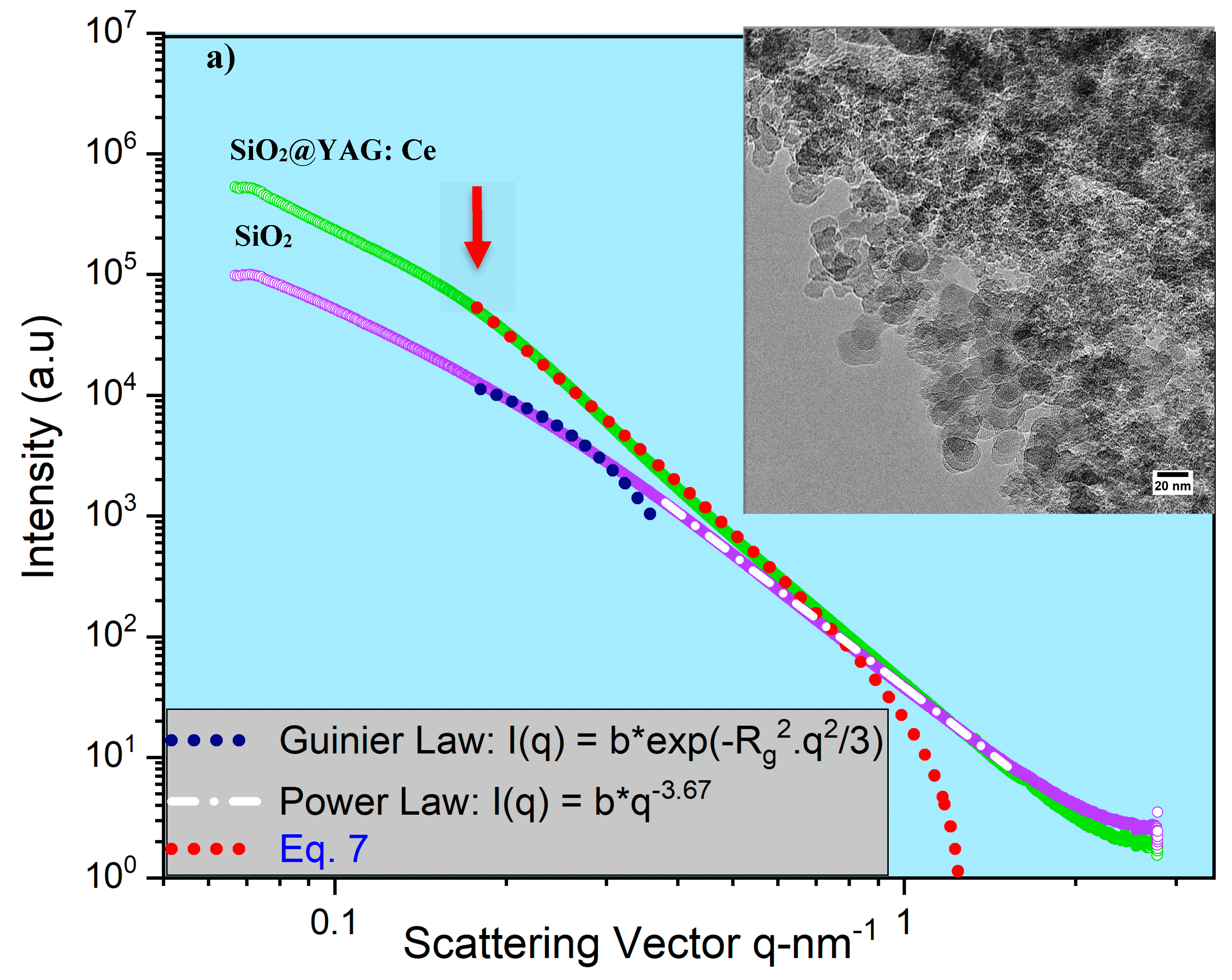
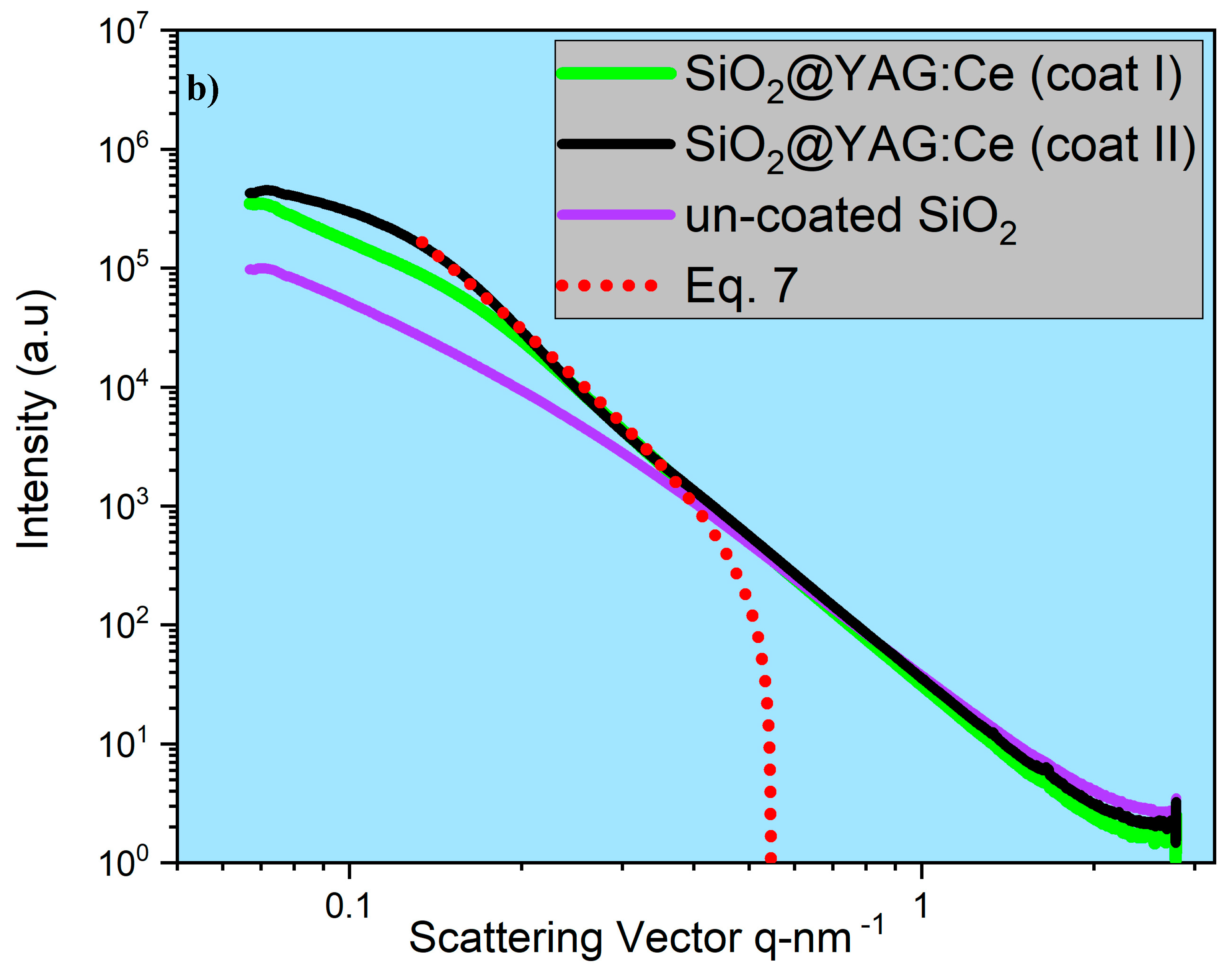
SAXS analysis showed that the mean thickness of YAG:Ce shell after one and two coating cycles were 2.8 nm and 7.7 nm. This was in agreement in HRTEM observations.
-
Heating the sample up to 10 h hardly resulted in any change in the morphology of nanoparticles, inferring that SiO2 cores were still encapsulated by YAG:Ce shell, obviously showing perfect thermal stability of SiO2@YAG:Ce core–shell nanoparticles.
-
SiO2@YAG:Ce (1.0 at.% Ce) core–shell nanoparticles show the highest emission, compared to commercial and synthesized SiO2/YAG:Ce mixture composite.
-
The number of coating cycles played a vital role in enhancing the PL intensity of the core–shell particles. The increase in the PL intensity with double coating cycle was obviously attributable to the increase of the shell thickness (YAG:Ce) on the SiO2 cores, which in turn increased emitting ions (Ce3+) per core–shell particle.

Author Contributions

Conceptualization, M.K.K. and A.B.; methodology, M.K.K., A.B. and M.Y.M.; formal analysis, M.K.K., A.B. and M.Y.M.; resources, M.K.K., M.Y.M., and A.B.; data curation, M.K.K., A.B., M.Y.M.; visualization, M.K.K.; writing—original draft preparation, M.K.K.; writing—review and editing, A.B., M.Y.M., M.K.K., W.D.v.D., G.Z.; Investigation, M.K.K. and M.Y.M.; Supervision, A.B., W.D.v.D. and G.Z. All authors have read and agree to the published version of the manuscript.

Funding

The SAXS experiments were performed on beamline DUBBLE (beam number 26-02-894 and file number 195.068.1155) at the European Synchrotron Radiation Facility (ESRF), Grenoble, France.

Acknowledgments

We are grateful to local contacts at the ESRF for providing assistance in using beamline DUBBLE. Authors would also like to thank Netherlands Organization for Scientific Research (NOW) for support in doing SAXS experiments. Authors would also like to thank Delft University of Technology for support in publishing this manuscript.

Conflicts of Interest

The authors declare no conflict of interest.

References

  1. Rajendran, M.; Samal, S.K.; Vaidyanathan, S. A novel self-activated (bluish-green) and Eu3+ doped (red) phosphors for warm white LEDs. J. Alloys Compd. 2020, 815, 152631. [Google Scholar] [CrossRef]
  2. Adam, J.; Metzger, W.; Koch, M.; Rogin, P.; Coenen, T.; Atchison, J.S.; König, P. Light emission intensities of luminescent Y2O3:Eu and Gd2O3:Eu particles of various sizes. Nanomaterials 2017, 7, 26. [Google Scholar] [CrossRef] [PubMed] [Green Version]
  3. Wu, Y.C.; Wang, D.Y.; Chen, T.M.; Lee, C.S.; Chen, K.J.; Kuo, H.C. A novel tunable green- to yellow-emitting β-YFS:Ce3+ phosphor for solid-state lighting. ACS Appl. Mater. Interfaces 2011, 3, 3195–3199. [Google Scholar] [CrossRef]
  4. Du, J.; Poelman, D. Facile synthesis of mn4+-activated double perovskite germanate phosphors with near-infrared persistent luminescence. Nanomaterials 2019, 9, 1759. [Google Scholar] [CrossRef] [Green Version]
  5. Ho, W.-J.; Liu, J.-J.; Lin, Z.-X.; Shiao, H.-P. Enhancing photovoltaic performance of GaAs single-junction solar cells by applying a spectral conversion layer containing Eu-doped and Yb/Er-doped phosphors. Nanomaterials 2019, 9, 1518. [Google Scholar] [CrossRef] [Green Version]
  6. Yazdan Mehr, M.; Bahrami, A.; van Driel, W.D.; Fan, X.J.; Davis, J.L.; Zhang, G.Q. Degradation of optical materials in solid-state lighting systems. Int. Mater. Rev. 2019, 65, 102–128. [Google Scholar] [CrossRef] [Green Version]
  7. Yazdan Mehr, M.; Toroghinejad, M.R.; Karimzadeh, F.; van Driel, W.D.; Zhang, G.Q. A review on discoloration and high accelerated testing of optical materials in LED based-products. Microelectron. Reliab. 2018, 81, 136–142. [Google Scholar] [CrossRef]
  8. Yazdan Mehr, M.; Volgbert, S.; van Driel, W.D.; Zhang, G.Q. Effects of graphene monolayer coating on the optical performance of remote phosphors. J. Electron. Mater. 2017, 46, 5866–5872. [Google Scholar] [CrossRef] [Green Version]
  9. Mehr, M.Y.; van Driel, W.D.; Zhang, G.Q. Reliability and lifetime prediction of remote phosphor plates in solid-state lighting applications using accelerated degradation testing. J. Electron. Mater. 2016, 45, 444–452. [Google Scholar] [CrossRef] [Green Version]
  10. Kiani Khouzani, M.; Bahrami, A.; Yazdan Mehr, M. Spark plasma sintering of Stellite®-6 superalloy. J. Alloys Compd. 2019, 782, 461–468. [Google Scholar] [CrossRef]
  11. Yazdan Mehr, M.; van Driel, W.D.; Zhang, G.Q. Progress in Understanding color maintenance in solid-state lighting systems. Engineering 2015, 1, 170–178. [Google Scholar] [CrossRef] [Green Version]
  12. Consulting, N. Energy Savings Forecast of Solid-State Lighting in General Illumination Applications; Navigant Consulting Inc.: Washington, DC, USA, 2014; pp. 2013–2014. [Google Scholar]
  13. Nhan, N.H.K.; Minh, T.H.Q.; Anh, N.D.Q. Influence of scattering enhancement particles CaCO3, CaF2, SiO2 and TiO2 on color uniformity of white LEDs. Appl. Phys. 2016, 14, 615–620. [Google Scholar] [CrossRef]
  14. Lai, M.F.; Quoc Anh, N.D.; Ma, H.Y.; Lee, H.Y. Scattering effect of SiO2 particles on correlated color temperature uniformity of multi-chip white light LEDs. J. Chin. Inst. Eng. 2016, 39, 468–472. [Google Scholar] [CrossRef]
  15. Hsu, C.H.; Chan, Y.C.; Chen, W.C.; Chang, C.H.; Liou, J.K.; Cheng, S.Y.; Guo, D.F.; Liu, W.C. Study of GaN-based LEDs with hybrid SiO 2 microsphere/nanosphere antireflection coating as a passivation layer by a rapid convection deposition. IEEE Trans. Electron Devices 2017, 64, 1134–1139. [Google Scholar] [CrossRef]
  16. Chung, Y.S.; Jeon, M.Y.; Kim, C.K. Performance changes of surface coated red phosphors with silica nanoparticles and silica nanocomposites. Ind. Eng. Chem. Res. 2009, 48, 740–748. [Google Scholar] [CrossRef]
  17. Yom, H.S.; Yang, J.K.; Polyakov, A.Y.; Lee, I.H. Performance of InGaN/GaN light emitting diodes with n-GaN layer embedded with SiO2 nano-particles. Appl. Sci. 2018, 8, 1574. [Google Scholar] [CrossRef] [Green Version]
  18. Nguyen, A.Q.D.; Nguyen, V.H. Application of CaCO3, CaF2, SiO2, and TiO2 particles to silicone lens for enhancing angular color uniformity of white LED lamp. In Journal of Physics: Conference Series, Proceedings of the 6th International Conference on Manufacturing Engineering and Process, Lisbon, Portugal, 27–29 May 2017; Institute of Physics Publishing: Bristol, UK, 2017; Volume 885. [Google Scholar]
  19. Lee, J.; Kwon, Y.Y.; Choi, E.-H.; Park, J.; Yoon, H.; Kim, H. Enhancement of light-extraction efficiency of organic light-emitting diodes using silica nanoparticles embedded in TiO2 matrices. Opt. Express 2014, 22, A705–A714. [Google Scholar] [CrossRef]
  20. Suresh, C.; Nagabhushana, H.; Basavaraj, R.B.; Darshan, G.P.; Kavyashree, D.; Daruka Prasad, B.; Sharma, S.C.; Vanithamani, R. SiO2@LaOF:Eu3+ core-shell functional nanomaterials for sensitive visualization of latent fingerprints and WLED applications. J. Colloid Interface Sci. 2018, 518, 200–215. [Google Scholar] [CrossRef]
  21. Komahal, F.F.; Nagabhushana, H.; Basavaraj, R.B.; Darshan, G.P.; Prasad, B.D.; Sharma, S.C.; Kavyashree, D. Design of Bi-functional composite core–shell SiO2@ZnAl2O4:Eu3+ array as a fluorescent sensors for selective and sensitive latent fingerprints visualization protocol. Adv. Powder Technol. 2018, 29, 1991–2002. [Google Scholar] [CrossRef]
  22. Sandhyarani, A.; Kokila, M.K.; Darshan, G.P.; Basavaraj, R.B.; Daruka Prasad, B.; Sharma, S.C.; Lakshmi, T.K.S.; Nagabhushana, H. Versatile core—Shell SiO2@SrTiO3:Eu3+, Li + nanopowders as fluorescent label for the visualization of latent fingerprints and anti-counterfeiting applications. Chem. Eng. J. 2017, 327, 1135–1150. [Google Scholar] [CrossRef]
  23. Rafiaei, S.M.; Isfahani, T.D.; Afshari, H.; Shokouhimehr, M. Improved optical properties of YVO4:Eu3+ nano—Layers on silica spheres. Mater. Chem. Phys. 2018, 203, 274–279. [Google Scholar] [CrossRef]
  24. Peng, G.H.; Wang, X.; Liang, Z.H.; Wang, Y.C.; Han, X.B.; Wu, J.L. Preparation of spherical core-shell structured SiO2@CaMoO4:Eu3+, Li+ red phosphors. J. Alloys Compd. 2013, 576, 227–231. [Google Scholar] [CrossRef]
  25. Ju, X.; Li, X.; Yang, Y.; Li, W.; Tao, C.; Feng, W. Luminescence properties of core-shell structured SiO2@CaMoO4:Eu3+ phosphor. J. Solid State Chem. 2012, 187, 109–113. [Google Scholar] [CrossRef]
  26. Wang, G.; Zou, H.; Gong, L.; Shi, Z.; Xu, X.; Sheng, Y. Synthesis and luminescent properties of monodisperse core-shell structured SiO2@Lu2O3:Eu3+ microspheres. Powder Technol. 2014, 258, 174–179. [Google Scholar] [CrossRef]
  27. Lu, W.; Guo, X.; Luo, Y.; Li, Q.; Zhu, R.; Pang, H. Core-shell materials for advanced batteries. Chem. Eng. J. 2019, 355, 208–237. [Google Scholar] [CrossRef]
  28. Feng, H.P.; Tang, L.; Zeng, G.M.; Zhou, Y.; Deng, Y.C.; Ren, X.; Song, B.; Liang, C.; Wei, M.Y.; Yu, J. Core-shell nanomaterials: Applications in energy storage and conversion. Adv. Colloid Interface Sci. 2019, 267, 26–46. [Google Scholar] [CrossRef]
  29. Xia, G.; Zhou, S.; Zhang, J.; Xu, J. Structural and optical properties of YAG:Ce3+ phosphors by sol-gel combustion method. J. Cryst. Growth 2005, 279, 357–362. [Google Scholar] [CrossRef]
  30. Hassanzadeh-Tabrizi, S.A. Synthesis and luminescence properties of YAG:Ce nanopowder prepared by the Pechini method. Adv. Powder Technol. 2012, 23, 324–327. [Google Scholar] [CrossRef]
  31. Selim, F.A.; Khamehchi, A.; Winarski, D.; Agarwal, S. Synthesis and characterization of Ce:YAG nano-phosphors and ceramics. Opt. Mater. Express 2016, 6, 3704. [Google Scholar] [CrossRef]
  32. Boukerika, A.; Guerbous, L.; Brihi, N. Ce-doped YAG phosphors prepared via sol-gel method: Effect of some modular parameters. J. Alloys Compd. 2014, 614, 383–388. [Google Scholar] [CrossRef]
  33. Garnet-Y3Al5O12—ChemTube3D. Available online: https://www.chemtube3d.com/ss-ygarnet/ (accessed on 8 October 2019).
  34. Gutsche, A.; Meier, M.; Guo, X.; Ungerer, J.; Nirschl, H. Modification of a SAXS camera to study structures on multiple scales. J. Nanopart. Res. 2017, 19, 321. [Google Scholar] [CrossRef]
  35. Guo, X.; Wagner, M.; Gutsche, A.; Meyer, J.; Seipenbusch, M.; Nirschl, H. Laboratory SWAXS combined with a low-pressure impactor for quasi-online analysis of nanoparticles generated by spark discharge. J. Aerosol Sci. 2015, 85, 17–29. [Google Scholar] [CrossRef]
  36. Guo, X.; Gao, K.; Gutsche, A.; Seipenbusch, M.; Nirschl, H. Combined small- and wide-angle X-ray scattering studies on oxide-supported Pt nanoparticles prepared by a CVS and CVD process. Powder Technol. 2015, 272, 23–33. [Google Scholar] [CrossRef]
  37. Gutsche, A.; Guo, X.; Dingenouts, N.; Nirschl, H. Synthesis and small angle X-ray scattering (SAXS) characterization of silica spheres covered with gel-like particles formed by means of solvent evaporation. Powder Technol. 2015, 278, 257–265. [Google Scholar] [CrossRef]
  38. Guo, X.; Gutsche, A.; Nirschl, H. SWAXS investigations on diffuse boundary nanostructures of metallic nanoparticles synthesized by electrical discharges. J. Nanopart. Res. 2013, 15, 2058. [Google Scholar] [CrossRef]
  39. Gutsche, A.; Daikeler, A.; Guo, X.; Dingenouts, N.; Nirschl, H. Time-resolved SAXS characterization of the shell growth of silica-coated magnetite nanocomposites. J. Nanopart. Res. 2014, 16, 2475. [Google Scholar] [CrossRef]
  40. Fernandes, N.J.; Akbarzadeh, J.; Peterlik, H.; Giannelis, E.P. Synthesis and properties of highly dispersed ionic silica-poly (ethylene oxide) nanohybrids. ACS Nano 2013, 7, 1265–1271. [Google Scholar] [CrossRef] [Green Version]
  41. Grünewald, T.A.; Lassenberger, A.; van Oostrum, P.D.J.; Rennhofer, H.; Zirbs, R.; Capone, B.; Vonderhaid, I.; Amenitsch, H.; Lichtenegger, H.C.; Reimhult, E. Core-shell structure of monodisperse Poly (ethylene glycol)-grafted iron oxide nanoparticles studied by Small-Angle X-ray Scattering. Chem. Mater. 2015, 27, 4763–4771. [Google Scholar] [CrossRef]
  42. Nirschl, H.; Guo, X. Characterisation of structured and functionalised particles by small-angle X-ray scattering (SAXS). Chem. Eng. Res. Des. 2018, 136, 431–446. [Google Scholar] [CrossRef]
  43. Guo, X.; Gutsche, A.; Wagner, M.; Seipenbusch, M.; Nirschl, H. Simultaneous SWAXS study of metallic and oxide nanostructured particles. J. Nanopart. Res. 2013, 15, 1559. [Google Scholar] [CrossRef]
  44. Joo, S.H.; Park, J.Y.; Tsung, C.K.; Yamada, Y.; Yang, P.; Somorjai, G.A. Thermally stable Pt/mesoporous silica core-shell nanocatalysts for high-temperature reactions. Nat. Mater. 2009, 8, 126–131. [Google Scholar] [CrossRef] [PubMed]
  45. He, B.; Zhao, Q.; Zeng, Z.; Wang, X.; Han, S. Effect of hydrothermal reaction time and calcination temperature on properties of Au@CeO2 core–shell catalyst for CO oxidation at low temperature. J. Mater. Sci. 2015, 50, 6339–6348. [Google Scholar] [CrossRef]
  46. Yan, F.; Jiang, J.; Chen, X.; Tian, S.; Li, K. Synthesis and characterization of silica nanoparticles preparing by low-temperature vapor-phase hydrolysis of SiCl4. Ind. Eng. Chem. Res. 2014, 53, 11884–11890. [Google Scholar] [CrossRef]
  47. He, G.; Mei, L.; Wang, L.; Liu, G.; Li, J. Synthesis and luminescence properties of nano-/microstructured Y3Al5O12:Ce3+ microspheres by controlled glass crystallization. Cryst. Growth Des. 2011, 11, 5355–5361. [Google Scholar] [CrossRef]
  48. Xu, J.; Liu, B.; Liu, Z.; Gong, Y.; Hu, B.; Wang, J.; Li, H.; Wang, X.; Du, B. Design of laser-driven SiO2-YAG:Ce composite thick film: Facile synthesis, robust thermal performance, and application in solid-state laser lighting. Opt. Mater. 2018, 75, 508–512. [Google Scholar] [CrossRef]
  49. Ogi, T.; Nandiyanto, A.B.D.; Okino, K.; Iskandar, F.; Wang, W.N.; Tanabe, E.; Okuyama, K. Towards better phosphor design: Effect of SiO2 nanoparticles on photoluminescence enhancement of YAG:Ce. ECS J. Solid State Sci. Technol. 2013, 2, R91–95. [Google Scholar] [CrossRef]
  50. Pan, G.H.; Wu, H.; He, S.; Zhang, L.; Hao, Z.; Zhang, X.; Zhang, J. Dye-embedded YAG:Ce3+@SiO2 composite phosphors toward warm wLEDs through radiative energy transfer: Preparation, characterization and luminescence properties. Nanoscale 2018, 10, 22237–22251. [Google Scholar] [CrossRef]
  51. Sun, Y.H.; Yang, Z.M.; Xie, C.N.; Jiang, Z.H. Preparation and characteristics of core-shell structure Y3Al5O12:Yb3+@SiO2 nanoparticles. J. Alloys Compd. 2012, 528, 1–9. [Google Scholar] [CrossRef]
  52. Potdevin, A.; Chadeyron, G.; Boyer, D.; Mahiou, R. Sol-gel based YAG:Ce3+ powders for applications in LED devices. Phys. Status Solidi C 2007, 4, 65–69. [Google Scholar] [CrossRef]
  53. Zhang, L.; Lu, Z.; Zhu, J.; Yang, H.; Han, P.; Chen, Y.; Zhang, Q. Citrate sol-gel combustion preparation and photoluminescence properties of YAG:Ce phosphors. J. Rare Earths 2012, 30, 289–296. [Google Scholar] [CrossRef]
  54. He, X.; Liu, X.; Li, R.; Yang, B.; Yu, K.; Zeng, M.; Yu, R. Effects of local structure of Ce3+ ions on luminescent properties of Y3Al5O12:Ce nanoparticles. Sci. Rep. 2016, 6, 2238. [Google Scholar] [CrossRef] [PubMed] [Green Version]
  55. Wang, X.J.; Qu, Y.R.; Zhao, Y.L.; Chu, H. Bin Effect of the composition of lanthanide complexes on their luminescence enhancement by Ag@SiO2 core-shell nanoparticles. Nanomaterials 2018, 8, 98. [Google Scholar] [CrossRef] [PubMed] [Green Version]
  56. Falahatdoost, S.; Ara, M.H.M.; Shaban, Z.; Ghazyani, N. Optical investigation of shell thickness in light scattering SiO2 particle with TiO2 nanoshells and its application in dye sensitized solar cells. Opt. Mater. 2015, 47, 51–55. [Google Scholar] [CrossRef]
  57. Son, S.; Hwang, S.H.; Kim, C.; Yun, J.Y.; Jang, J. Designed synthesis of SiO2/TiO2 core/shell structure as light scattering material for highly efficient dye-sensitized solar cells. ACS Appl. Mater. Interfaces 2013, 5, 4815–4820. [Google Scholar] [CrossRef] [PubMed] [Green Version]
Figure 1. (a) Schematics of light emitting diode (LED) structure and (b) mechanism of white light generation.
Nanomaterials 10 00153 g001
Figure 2. (a) XRD spectrum and (b) FESEM image of nano-sized SiO2 particles.
Nanomaterials 10 00153 g002
Figure 3. An overview of the synthesis process.
Nanomaterials 10 00153 g003
Figure 4. (a) XRD patterns of YAG:Ce nanoparticles, synthesized using solutions with different pH values and (b) FESEM image of synthesized YAG:Ce powders.
Nanomaterials 10 00153 g004
Figure 5. Elemental mapping of a YAG:Ce nanoparticle.
Nanomaterials 10 00153 g005
Figure 6. (a) X-ray diffraction patterns of synthesized YAG:Ce nanoparticles and commercial YAG:Ce, (b) X-ray diffraction patterns of SiO2@YAG:Ce nanoparticles after annealing, and (c,d) crystal structure of YAG [33].
Nanomaterials 10 00153 g006
Figure 7. (a) Small angle X-ray diffraction (SAXS) curves of SiO2 and SiO2@YAG:Ce and (b) SAXS curves of SiO2 and SiO2@YAG:Ce (coat I and II).
Nanomaterials 10 00153 g007aNanomaterials 10 00153 g007b
Figure 8. SAXS curves of core shell nanoparticle calcined at 1000 °C for different times.
Nanomaterials 10 00153 g008
Figure 9. (a) High resolution transmission electron macroscopy (HRTEM) image of SiO2@YAG:Ce (coat I) and (b) TEM image of SiO2@YAG Ce (coat II), and (c) elemental mapping analysis.
Nanomaterials 10 00153 g009
Figure 10. FTIR spectra of SiO2 spheres, SiO2@YAG:Ce core shell phosphors, and that of pure YAG:Ce phosphors.
Nanomaterials 10 00153 g010
Figure 11. (a) Photoluminescence emission spectra of SiO2/YAG:Ce (commercial and synthesized) composite and SiO2@YAG:Ce core–shell particles and (b) luminescent main intensity of SiO2@YAG:Ce varying with the Ce concentrations and SiO2/YAG:Ce (commercial and synthesized composite).
Nanomaterials 10 00153 g011aNanomaterials 10 00153 g011b
Figure 12. Diffuse transmission spectra of (a) YAG:Ce and SiO2@YAG:Ce and (b) synthesized SiO2/YAG:Ce (1 at.%) composite and SiO2@YAG:Ce core–shell nanoparticles.
Nanomaterials 10 00153 g012aNanomaterials 10 00153 g012b

