
A Design Method to Assess the Primary Strength of the Delta-Type VLFS


Abstract
:1. Introduction
2. Materials and Methods
3. Results
3.1. Verification
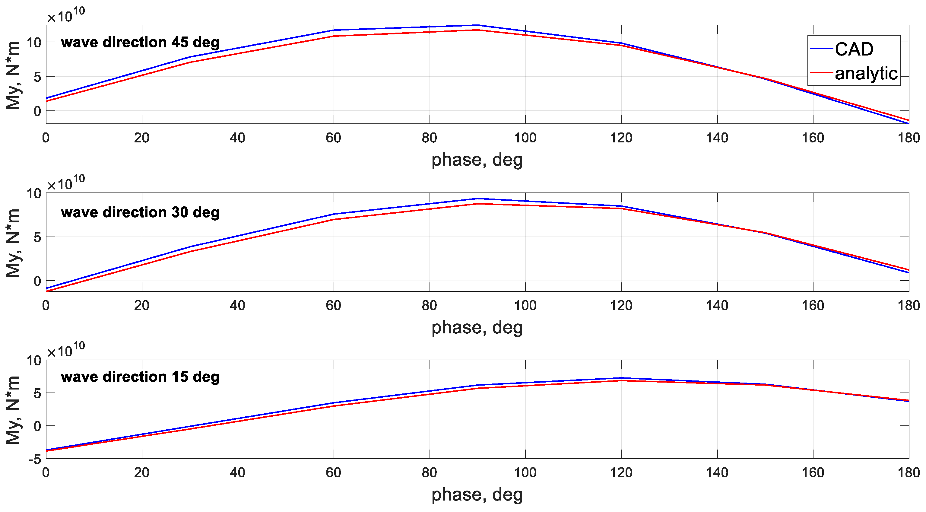
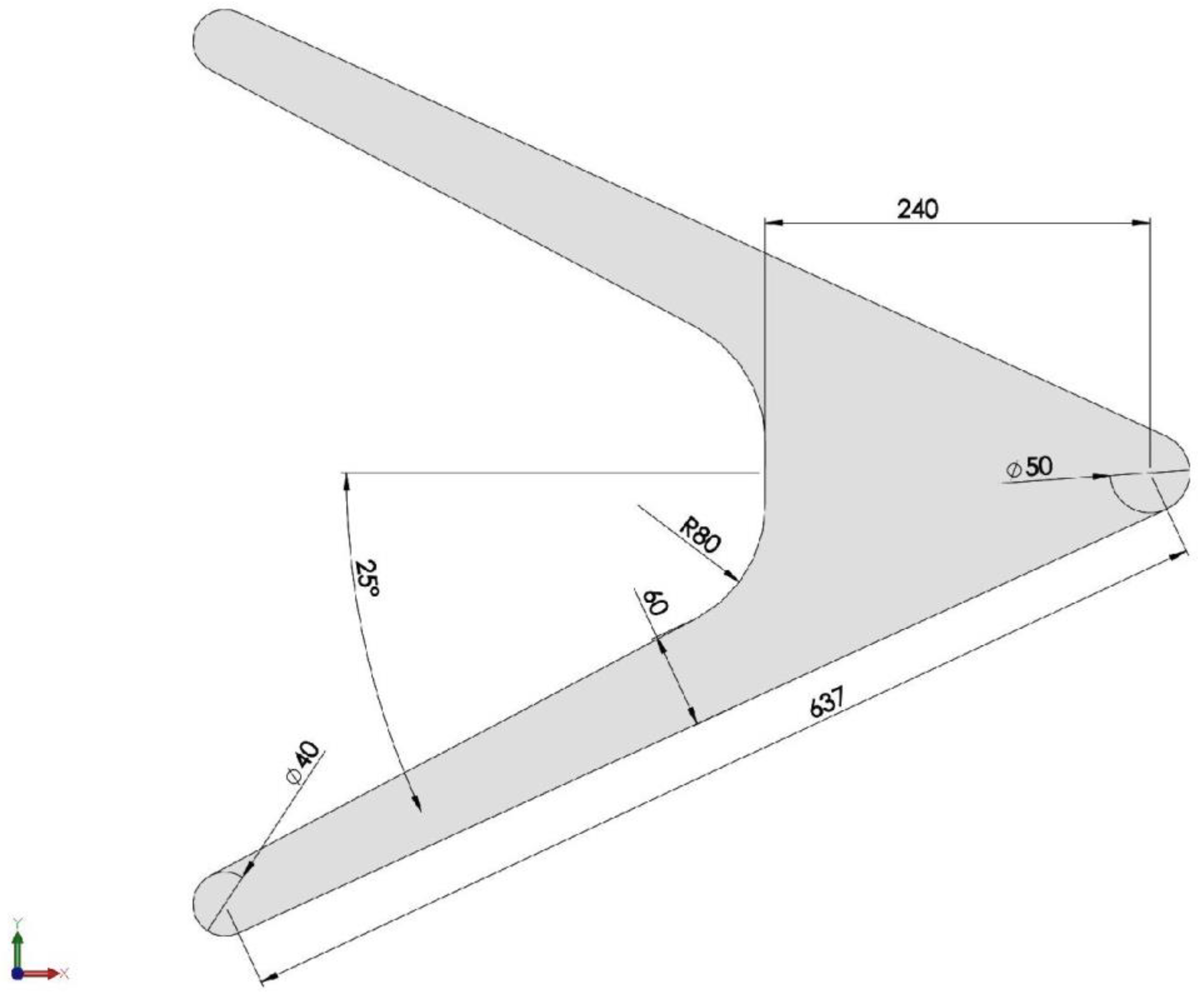
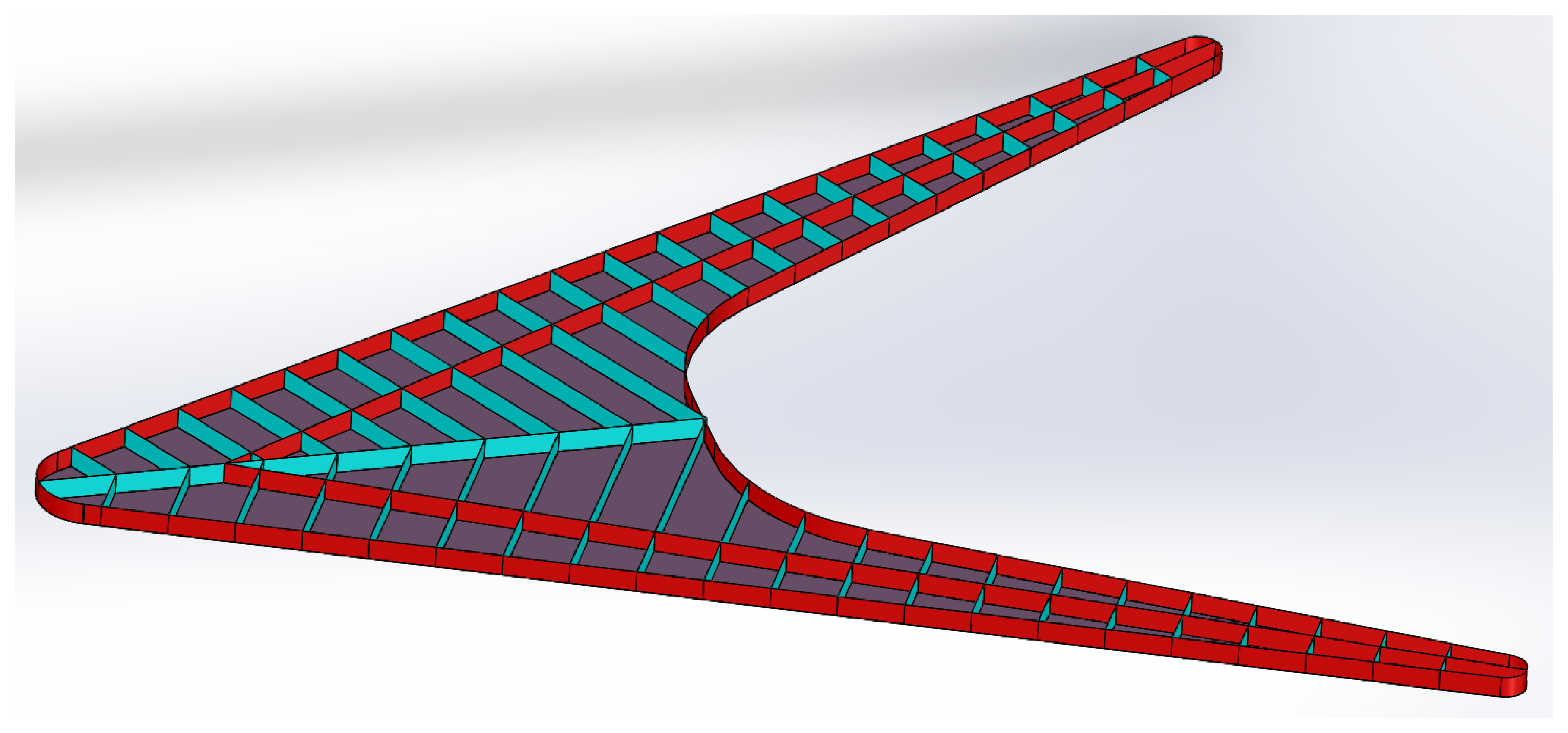
3.1.1. Comparison with Geometrical CAD Calculations
3.1.2. Comparing the Quasi-Static Primary Strength Loads with Hydrodynamic Splitting Forces
- A.
- External hydrodynamic
- B.
- Gravitational:
- C.
- Inertial:
3.2. Total Hydrodynamic Load Comparison: Validation of the Procedure
3.3. Implementation of the Design Procedure: Initial Results for Prismatic Side-Hulls
- Wave height: ;
- Wavelength: ;
- Wave phase: to , in intervals. Phase is where the wave crest is at LCG;
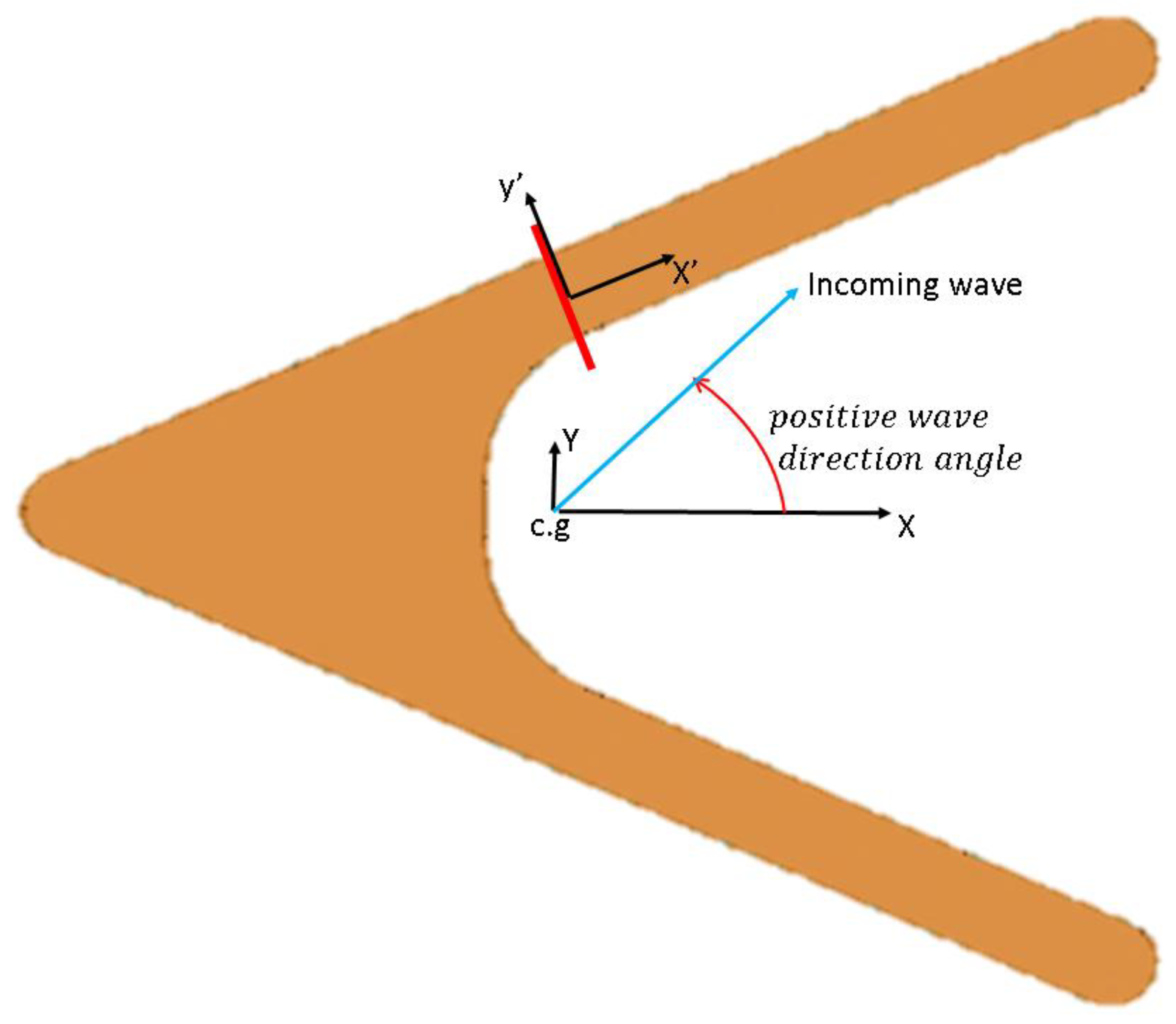
- Wave direction: ;
- The required bending moduli of the critical cross section are in the order of 1000 m3.
3.4. Implementation of the Design Procedure: More Efficient Narrow Stern Design
3.4.1. Load Results
- Wave height: ;
- Wavelength: ;
- Wave phase: to , in intervals. Phase is where the wave crest is at LCG;
- Wave direction: .
3.4.2. Initial Scantlings
4. Discussion
5. Conclusions
Author Contributions
Funding
Institutional Review Board Statement
Informed Consent Statement
Conflicts of Interest
References
- Wang, G.; Goldfeld, Y.; Drimer, N. Expanding coastal cities—Proof of feasibility for modular floating structures (MFS). J. Clean. Prod. 2019, 222, 520–538. [Google Scholar] [CrossRef]
- UNCTAD. Handbook of Statistics 2020—The World Development Status; United Nations Publications: New York, NY, USA, 2020; ISBN 9789211129977. [Google Scholar]
- Ranasinghe, R. On the need for a new generation of coastal change models for the 21st century. Sci. Rep. 2020, 10, 2020. [Google Scholar] [CrossRef]
- Wang, C.M.; Wang, B.T. Colonization of the ocean and VLFS technology. In Very Large Floating Structures; Wang, C.M., Watanabe, E., Utsunomiya, T., Eds.; Taylor & Francis: London, UK; New York, NY, USA, 2008; pp. 1–20. ISBN 9788578110796. [Google Scholar]
- Wang, C.M.; Tay, Z.Y. Very Large Floating Structures: Applications, Research and Development. Procedia Eng. 2011, 14, 62–72. [Google Scholar] [CrossRef] [Green Version]
- Wang, C.M.; Wang, B.T. Great Ideas Float to the Top. In Large Floating Structure: Technological Advances; Wang, C.M., Wang, B.T., Eds.; Springer Science Business Media: Singapore, 2015; p. 334. ISBN 978-981-287-137-4. [Google Scholar]
- Kim, J.-G.; Cho, S.-P.; Kim, K.-T.; Lee, P.-S. Hydroelastic design contour for the preliminary design of very large floating structures. Ocean Eng. 2013, 78, 112–123. [Google Scholar] [CrossRef]
- Wu, L.; Wang, Y.; Li, Y.; Xiao, Z.; Li, Q. Simplified algorithm for evaluating the hydrodynamic performance of very large modular semi-submersible structures. Ocean Eng. 2017, 140, 105–124. [Google Scholar] [CrossRef]
- Lamas-Pardo, M.; Iglesias, G.; Carral, L. A review of Very Large Floating Structures (VLFS) for coastal and offshore uses. Ocean Eng. 2015, 109, 677–690. [Google Scholar] [CrossRef]
- Drimer, N.; Gafter, R. Delta-type VLFS—hydrodynamic aspects. Ships Offshore Struct. 2017, 13, 352–365. [Google Scholar] [CrossRef]
- Hughes, F.O.; Paik, J.K. Ship Structural Analysis and Design; The Society of Naval Architects and Marine Engineers: Jersey City, NY, USA, 2010. [Google Scholar]
- Sidari, M.; Andric, J.; Jelovica, J.; Underwood, J.M.; Ringsberg, J.W. Influence of different wave load schematisation on global ship structural response. Ships Offshore Struct. 2019, 14, 9–17. [Google Scholar] [CrossRef]
- Payer, H.G.; Schellin, T.E. A class society’s view on rationally based ship structural design. Ships Offshore Struct. 2013, 8, 319–336. [Google Scholar] [CrossRef]
- McNatt, T.; Ma, M.; Hunter, S. Historical perspective on the structural design of special ships and the evolution of structural design methods. Ships Offshore Struct. 2013, 8, 404–414. [Google Scholar] [CrossRef]
- Suzuki, H.; Bhattacharya, B.; Fujikubo, M.; Hudson, D.A.; Riggs, H.R.; Seto, H.; Shin, H.; Shugar, T.A.; Yasuzawa, Y.; Zong, Z. ISSC 2006—Committee VI.2: Very Large Floating Structures. In Proceedings of the 16th International Ship and Offshore Structures Congress, Southampton, UK, 20 August 2006; Volume 2, pp. 1–236. [Google Scholar]
- Pei, Z.; Iijima, K.; Fujikubo, M.; Tanaka, S.; Okazawa, S.; Yao, T. Simulation on progressive collapse behaviour of whole ship model under extreme waves using idealized structural unit method. Mar. Struct. 2015, 40, 104–133. [Google Scholar] [CrossRef]
- Odijie, A.C.; Quayle, S.; Ye, J. Wave induced stress profile on a paired column semisubmersible hull formation for column reinforcement. Eng. Struct. 2017, 143, 77–90. [Google Scholar] [CrossRef] [Green Version]
- Cariou, A.; Jancart, F. Influence of modelling on calculated sea loads on ships. Mar. Struct. 2003, 16, 149–173. [Google Scholar] [CrossRef]
- Phelps, B.P. DSTO-RR-0116: Determination of Wave Loads for Ship Structural Analysis; Aeronautical and Maritime Research Laboratory: Melborne, Australia, 1997.
- Tatsumi, A.; Fujikubo, M. Ultimate strength of container ships subjected to combined hogging moment and bottom local loads part 1: Nonlinear finite element analysis. Mar. Struct. 2019, 69, 102683. [Google Scholar] [CrossRef]
- Liu, B.; Soares, C.G. Ultimate strength assessment of ship hull structures subjected to cyclic bending moments. Ocean Eng. 2020, 215, 107685. [Google Scholar] [CrossRef]
- Yao, T. Hull Girder Strength. Mar. Struct. 2003, 16, 1–13. [Google Scholar] [CrossRef]
- Lee, D.H.; Kim, S.J.; Lee, M.S.; Paik, J.K. Ultimate limit state based design versus allowable working stress based design for box girder crane structures. Thin-Walled Struct. 2019, 134, 491–507. [Google Scholar] [CrossRef]
- Paik, J.K.; Wang, G.; Kim, B.J.; Thayamballi, A.K. Ultimate Limit State Design of Ship Hulls. 2002, Volume 110, pp. 473–496. Available online: https://www.zhangqiaokeyan.com/academic-journal-foreign_other_thesis/020419986339.html (accessed on 15 September 2021).
- Kuznecovs, A.; Ringsberg, J.W.; Johnson, E.; Yamada, Y. Ultimate limit state analysis of a double-hull tanker subjected to biaxial bending in intact and collision-damaged conditions. Ocean Eng. 2020, 209, 107519. [Google Scholar] [CrossRef]
- Yoshkawa, T.; Bayatfar, A.; Kim, B.J.; Chen, C.P.; Wang, D.; Boulares, J.; Gordo, J.M.; Josefson, L.; Smith, M.; Kaeding, P.; et al. Issc2015—Committee III 1: Ultimate Strength. In Proceedings of the 19th International Ship and Offshore Structures Congress, Cascais, Portugal, 7–10 September 2015. [Google Scholar]
- Paik, J.K.; Kim, B.J.; Seo, J.K. Methods for ultimate limit state assessment of ships and ship-shaped offshore structures: Part I—Unstiffened plates. Ocean Eng. 2008, 35, 261–270. [Google Scholar] [CrossRef]
- International Association of Classification Societies. Common Structural Rules for Bulk Carriers and Oil Tankers; IACS: London, UK, 2020. [Google Scholar]
- Jagite, G.; Bigot, F.; Derbanne, Q.; Malenica, Š.; Le Sourne, H.; Cartraud, P. A parametric study on the dynamic ultimate strength of a stiffened panel subjected to wave- and whipping-induced stresses. Ships Offshore Struct. 2020, 1–15. [Google Scholar] [CrossRef]
- Kaminski, M.L.; Rigo, P. Progress in Marine Science and Technology. In Proceedings of the 20th International Ship and Offshore Structures Congress (ISSC 2018); Kaminski, M.L., Rigo, P., Eds.; IOS Pres BV: Amsterdam, The Netherlands, 2018; Volume 1, ISBN 978-1-61499-862-4. [Google Scholar]
- ANSYS Inc. AQWA Theory Manual; ANSYS Inc.: Canonsburg, PA, USA, 2013; Volume 15317. [Google Scholar]
- Journee, J.M.J.; Massie, W.W. Offshore Hydromechanics, 1st ed.; Delft University of Technology: Delft, The Netherlands, 2001; ISBN 9781457717659. [Google Scholar]


Publisher’s Note: MDPI stays neutral with regard to jurisdictional claims in published maps and institutional affiliations. |
© 2021 by the authors. Licensee MDPI, Basel, Switzerland. This article is an open access article distributed under the terms and conditions of the Creative Commons Attribution (CC BY) license (https://creativecommons.org/licenses/by/4.0/).
Share and Cite
Gafter, R.; Drimer, N. A Design Method to Assess the Primary Strength of the Delta-Type VLFS. J. Mar. Sci. Eng. 2021, 9, 1026. https://doi.org/10.3390/jmse9091026
Gafter R, Drimer N. A Design Method to Assess the Primary Strength of the Delta-Type VLFS. Journal of Marine Science and Engineering. 2021; 9(9):1026. https://doi.org/10.3390/jmse9091026
Chicago/Turabian StyleGafter, Roy, and Nitai Drimer. 2021. "A Design Method to Assess the Primary Strength of the Delta-Type VLFS" Journal of Marine Science and Engineering 9, no. 9: 1026. https://doi.org/10.3390/jmse9091026